Article

A Novel Single-Fed Dual-Band Dual-Circularly Polarized Dielectric Resonator Antenna for 5G Sub-6GHz Applications

1
School of Electrical and Electronic Engineering, Engineering Campus, Universiti Sains Malaysia, Nibong Tebal 14300, Penang, Malaysia
2
Electrical Engineering Department, Gomal University, Dera Ismail Khan 29050, Pakistan
3
Department of Electrical Engineering, Baluchistan University of Information Technology, Engineering and Management Sciences, Quetta 87300, Pakistan
4
Department of Electrical Engineering, National University of Sciences and Technology, H-12, Islamabad 44000, Pakistan
5
Faculty of Aviation Sciences, Amman Arab University, Amman 11953, Jordan
6
Systems Engineering Department, Military Technological College, Muscat 111, Oman
7
Department of Electrical and Electronics Engineering Technology, University of Technology, Nowshera 24100, Pakistan
8
Department of Computer Science, COMSATS University, Abbottabad Campus, Abbottabad 22020, Pakistan
9
Department of Signal Theory and Communications, Universidad Carlos III de Madrid, 28911 Leganés, Madrid, Spain
10
School of Electrical Engineering and Computer Science, KTH Royal Institute of Technology, SE 100-44 Stockholm, Sweden
*
Authors to whom correspondence should be addressed.
Appl. Sci. 2022, 12(10), 5222; https://doi.org/10.3390/app12105222
Submission received: 3 April 2022 / Revised: 10 May 2022 / Accepted: 19 May 2022 / Published: 21 May 2022

Abstract

:
In this research article, a single-fed dual-band circular polarized (CP) dielectric resonator antenna (DRA) for dual-function communication, such as GPS and WLAN, was made. Initially, the proposed design process was initiated by designing a linearly polarized singly fed-DRA. To attain CP fields, the cross-shape conformal metal strip was optimized to excite the fundamental and the high-order mode in the two frequency bands. The metallic strip (parasitic) was utilized on top of the rectangular DRA to improve and widen the impedance and axial ratio (AR) bandwidth. This step led to a 2.73% improvement on the lower band and an impact of 6.5% on the upper band while on the other side a significant improvement was witnessed in the AR bandwidth in both frequency bands. A prototype was designed and fabricated in order to validate its operations. The measurement outcomes of the proposed antennas authenticated wideband impedance bandwidths of 6.4% and 25.26%, and 3-dB axial ratios (AR) of 21.26% and 27.82% respectively. The prototype is a decent candidate for a global positioning system (GPS) and wireless local area network (WLAN).

1. Introduction

Due to their merits such as less ohmic losses, integrally wide bandwidth, compactness, relatively high radiation efficiency, less surface-wave loss, ease of excitation, and a high degree of design independence, dielectric resonator antennas (DRAs) have received much attention in the literature and have been extensively studied over the last two decades [1]. DRAs can readily be integrated into other components such as a coupler and oscillator because of these advantages [2]. Additionally, dielectric resonators (DRs) are anticipated to be used in active integrated systems such as active integrated antennas (AIAs) [3].
Circular polarized antennas are beneficial in several areas, including mobile, radar, satellite, and other communications systems, due to the advantages of mitigating polarization discrepancy, suppressing multiple multipath reflections/different types of interventions, improving channel capacity, and system reliability. As a result, circularly polarized DRAs may readily control the limitations imposed by their LP counterparts [4,5,6,7,8]. Circular polarization in an antenna has been achieved using a variety of approaches, which can be split into two categories: single-fed and multiple-fed systems. Though multiple-point-fed models required more room to create the requisite antenna, they can attain wider bandwidths than single-fed devices [9]. Putting hybrid couplers underneath the DRAs is one way for shrinking the size of the circularly polarized antenna. This procedure gives a significant 3-dB axial ratio (AR) and Impedance matching (S11) bandwidths with a small-scale footprint [10].
Modifying DR shapes such as stair-shape [11], rotating stair [12], trapezoidal [13], inverted sigmoid shape [14], parasitic metal strips on sidewalls or on adjoining metallic plates [15], and diagonally inclined slits with DR [16] are other techniques to extend bandwidths. The geometry of DRA was altered in an azimuthal direction occasionally in [16] to disintegrate tangential electric fields of boundaries orthogonally. Circularly polarized waves with an adequate AR bandwidth were created using a single-point feed. In contrast to [17], the same approach was used in [18] with an inclined slot and microstrip, resulting in a narrow 3 dB AR bandwidth.
In [19], changing the geometrical shape of a trapezoidal DRA with a notch at its top enhances the Impedance matching bandwidth, and as a result, a noteworthy 3-dB AR ratio bandwidth has been achieved with the use of an inclined slot. In [20], a DRA has an aperture-coupled stair shape, which is made up of two rotatable rectangular DR. In dual bands, this change results in a wide impedance and AR bandwidth. Printing a conducting loop on DRA can produce circularly polarized waves, resulting in a wider AR bandwidth [21]. The strips on the DRA sidewall not only degenerate two orthogonal modes with a small AR bandwidth, but they were also wonderfully shrunk [22].
Ref. [23] demonstrated that with this approach, 3-dB AR bandwidth can be achieved in MIMO DRAs. The bandwidth was boosted by placing DRA without a gap, which results in a higher length to width (L/W) aspect ratio. Furthermore, to increase Impedance matching and AR bandwidth, the approach [24,25] can be used with vertical metallic plates across the DR. Another way to increase bandwidth is to use slanted holes on the diagonal and sidewalls of DR [26] to achieve CP waves. It is important to remember that each of the processes listed above has its own set of fabrication issues.
On the other hand, as wireless communication systems explore dual-band, CP DRAs have gotten a lot of interest [27,28]. An external quadrature coupler degenerates the fundamental HEM111 and higher-order HEM113 modes in a dual-fed dual-band Circularly polarized DRA. AR bandwidths of 12.4 percent for the lower bands and 7.4 percent for the higher bands are achieved with this design [29]. This model, however, necessitates a sophisticated feeding network, which considerably increases the size. A single-fed dual-band Circularly polarized chamfered DRA was published in parallel [30]. The AR bandwidths are comparatively narrow, with just 5.2% and 1.4% for the bottom and upper bands, respectively, despite the model’s modest feeding network. In contrast to the DRA in [31], which uses a diagonal groove on the top face of the DRA to increase AR bandwidth [32], the DRA in [32] uses a design with a diagonal groove on the top face of the DRA to increase AR bandwidth. Unfortunately, the increase in AR bandwidth is not significant, with only 6.3% and 6.8% for the lower and upper bands, respectively. A customized circular patch on top of CP DRA is investigated in [33]. It has relatively narrow 3-dB AR bandwidths of 3.16% and 5.06%.
Mostly, single-fed structures are chosen for the merits of high aperture efficiency, reduced loss, and compact size. Orthogonal circularly polarized waves with anticipated phase differences can be attained by multi-resonant modes of the radiator rather than the feeding network [34]. Indeed, it is challenging to design dual-band dual-CP antennas.
In this research article, a single-fed dual-band circularly polarized DRA is proposed for GPS and WLAN communications. In section II, initially, a Linear polarized DRA is excited through a single conformal metal strip, and then circularly polarized radiation is achieved by cross shape feed structure. To generate dual-band performance, RDRA is excited in its fundamental quasi-TE111 mode and higher-order quasi-TE113 mode based on the cross-shaped feed. The cross-shape conformal metal feed achieves Orthogonal Circularly polarized wave characteristics. The metal strip on top of RDRA gives the antenna more gain and a wider AR bandwidth (ARBW), ensuring reliable GPS/WLAN communications and overcoming the disadvantages of single-fed antennas’ limited ARBWs. In addition, in section II, a design guideline was introduced to further clarify the process (1–5). Section III also includes a description of the antenna fabrication process as well as measurement findings. The suggested design has 6.4% and 25.26% impedance bandwidths, respectively, with 3-dB AR bandwidths of 21.26% (lower) and 27.82% (upper), as well as 7.7 and 5.9 dBi maximum gain. The proposed antenna’s reflection coefficients, ARs, radiation patterns, and gains are investigated, with the reasonable agreement between measured and simulated findings.

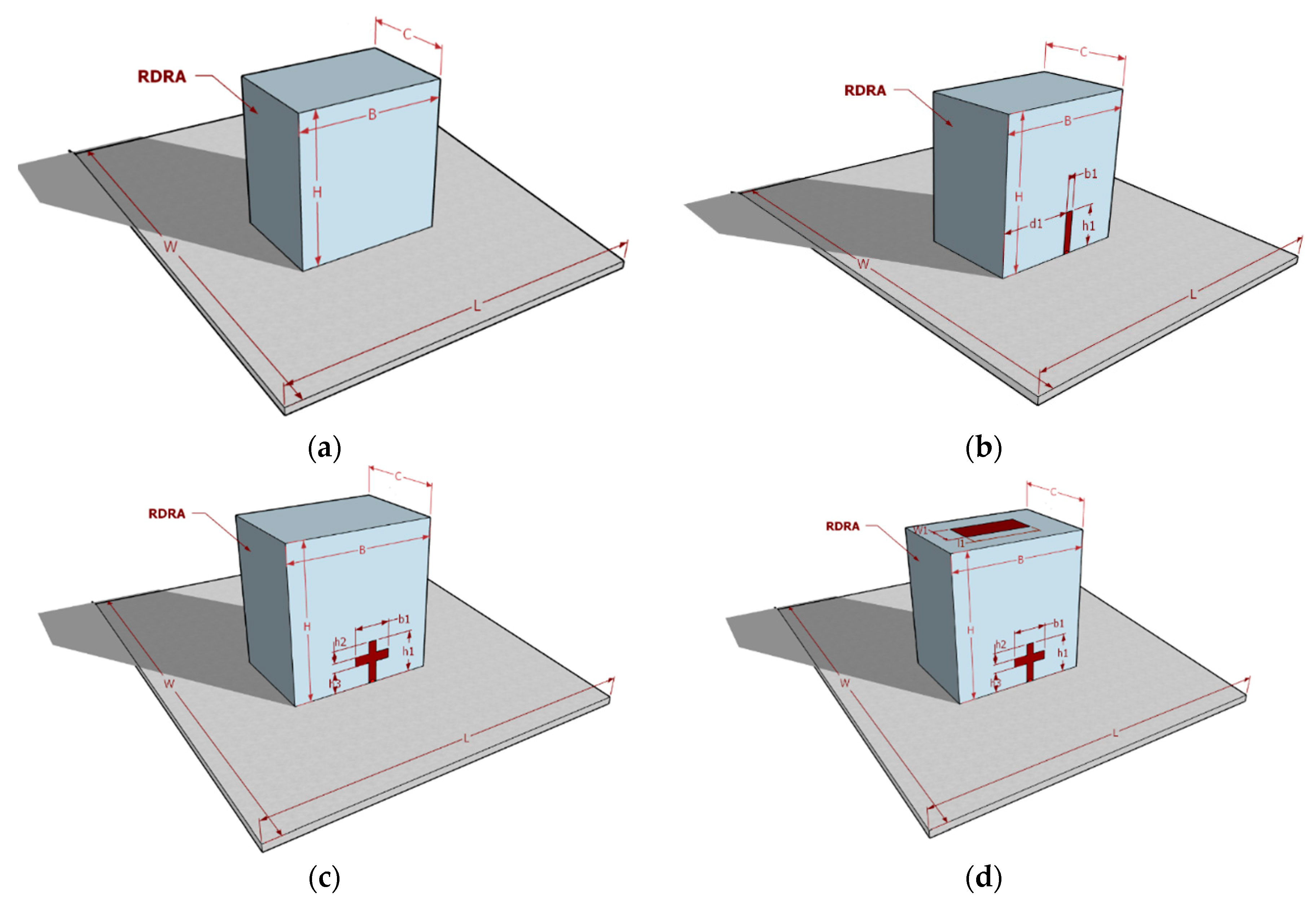
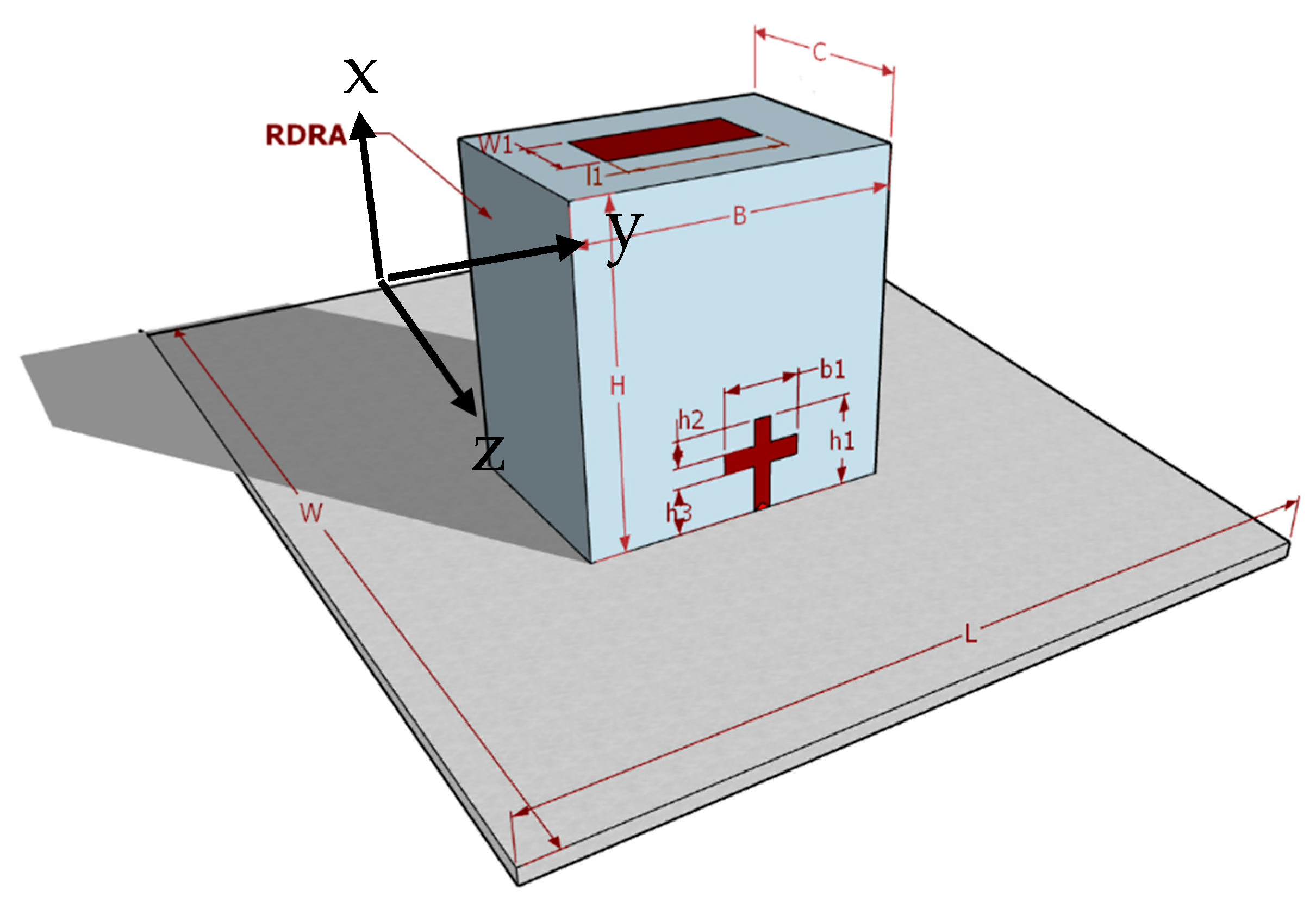
2. Antenna Design and Analysis

In this unit, the configuration of circularly polarized RDRA is elucidated. In Section II-A, the focus is on designing and optimizing a linearly polarized DRA at its maximum possible impedance bandwidth with a single conformal metal strip Moreover, further changing the single metal strip to cross shape feed with optimized parameters in order to excite the orthogonal waves for the generation of circular polarization. In Section II-B, to provide good AR bandwidth, a metal strip structure is introduced and optimized at top of the RDRA. Finally, desired antennas are designed with desired dual CP performance as depicted in Figure 1.

Linear Polarized DRA

To initiate with, singly fed simple DRA which is made up of a Rectangular DR excited through singly feed mechanism is designed. DR is made of ECCOSTOCK HIK with εr = 9.8 and tanδ = 0.002, mounted on the PEC ground plate. Figure 2 depicts the proposed antenna’s geometric development process. Figure 2a shows the three-dimensional and cross-sectional views of an RDRA. The dimensions of the rectangular DR are kept similar as in [20], with a height (H), width (B), and depth of (C) 26.1 mm, 25.4 mm, and = 14.3 mm, respectively.
The dimensions of proposed DRA are given in Table 1. The initial model was designed and analyzed using the dielectric waveguide model [8]. By placing the DRA on a ground plane even modes will be short-circuited and only the odd modes can exist [7]. Because of this principle, TE modes (odd modes) are excited. In parallel, the resonant frequency of the fundamental mode, TE111, is calculated by means of the equations [9] where. kx, ky, and kz respectively denote the wavenumbers in the x, y, and z directions inside the DRA, as shown in Equation (1).
f 0 = c 2 π ε r k x 2 + k y 2 + k z 2
k x = π c
k z = π 2 H
Moreover, the 3-dB AR is defined by:
E y E x = | E y | | E x |   *   e j Ҩ
The electric field vector’s y-directed component is Ey, while the x-directed component is Ex. The difference in phase between Ex and Ey the amplitude ratio is 1, and the phase difference (ɸ) is 90° for pure circular polarization’s standard performance. The single feed RDRA (Figure 2b) can obviously achieve dual-band operation, but it does not have a CP mode.
The optimized parameter for the single conformal metal strips of the RDRA based on rigorous parametric analysis using the CST tool is mentioned in Table 2. This presents the impedance matching bandwidth; the aforementioned bandwidth is sensitive to the strip height, as changing the height may deteriorate the results. The dimensions of the strip were optimized based on running the parametric sweep, and the optimized dimensions of the individual strips were found to be h1 = 11.75 mm, and b1 = 1 mm. The optimized feed parameters provide S11 bandwidths of ~7.19%.
The impedance matching bandwidth (S11) of the RDRA can be controlled and optimized by adjusting the position of the feed as well. Therefore, a parametric study was conducted for different values of d1 as well. As depicted in Figure 2b schematic diagram of the optimum value of d1, while Figure 3 shows the various reflection coefficient characteristics of the single element DRA with the different values of d1 = 7.5 mm, 8.0 mm, and 8.5 mm from the edge. It is observed that each value of “d1” produces a different value of the reflection coefficient. As the value changes, the resonant frequency is shifted upward (higher frequencies), and the best return loss is achieved when keeping the distance at d1 = 8 mm.
So far the optimized feed parameters and feed location were finalized. Single feed conformal metal strip of the RDRA provides a simulated reflection coefficient (S11) bandwidth of ~ 7.19%, covering the frequency range from 3.61–3.91 GHz and gain of ~5.2 dBi over the same frequency range as shown in Figure 4; moreover the single feed cannot excite the circularly polarized fields, therefore, the design is said to be linearly polarized and in order to energize the RDRA single feed, a discrete edge port was used.
To generate and examine the circular polarization field, the geometric evolution process of the anticipated antenna is depicted in Figure 2. In Figure 2b, an RDRA is designed as the initial model, following the dielectric waveguide model design principle. Then, the new feed was applied to make the cross-shaped structure. In order to simplify the antenna, a new feed is introduced which makes the design cross shape. The cross-shape feed is usually symmetrical, which means the length and width of both strips are identical. i.e., (height) b1 = 11.75 mm and (width) w2 = 1 mm. Applying asymmetrical cross shape feed can help to attain decent circular polarized waves. The possibility of the generation of circular polarization of linearly polarized DRA by employing a new change in the design is depicted in Figure 2c. Based on the cross-shaped feed, RDRA is excited in its fundamental quasi-TE111 mode at 3.41 GHz and the higher-order mode (TE113) at 4.20 GHz which is visible in Figure 5.
The new configuration has not so significant impact on return loss infect simulated center frequency may shift to the left side from 3.70 GHz to 3.45 GHz. Because of the reduction of dielectric due to the conformal metal strip of the cross-shape feed, the effective dielectric of the RDRA reduces, and because of this resonant frequency shifts downwards. [7]. Simulated reflection coefficients and ARs are plotted in Figure 6. The AR bands of cross slot RDRA are100% in accord with the Impedance matching bandwidth in a lower band while the overlapping ratio in the upper band is below 1%. As shown the cross-shape feeds operate at two frequency bands. the simulated impedance bandwidths of the lower and upper bands are 8.7% (3.30–3.60 GHz) and 7.14% (4.10–4.55 GHz), respectively. The light-yellow shaded part shows the Return Loss of the upper band and lower bands while the light blue shaded part demonstrates the overlapping part of the 3-dB axial ratio.

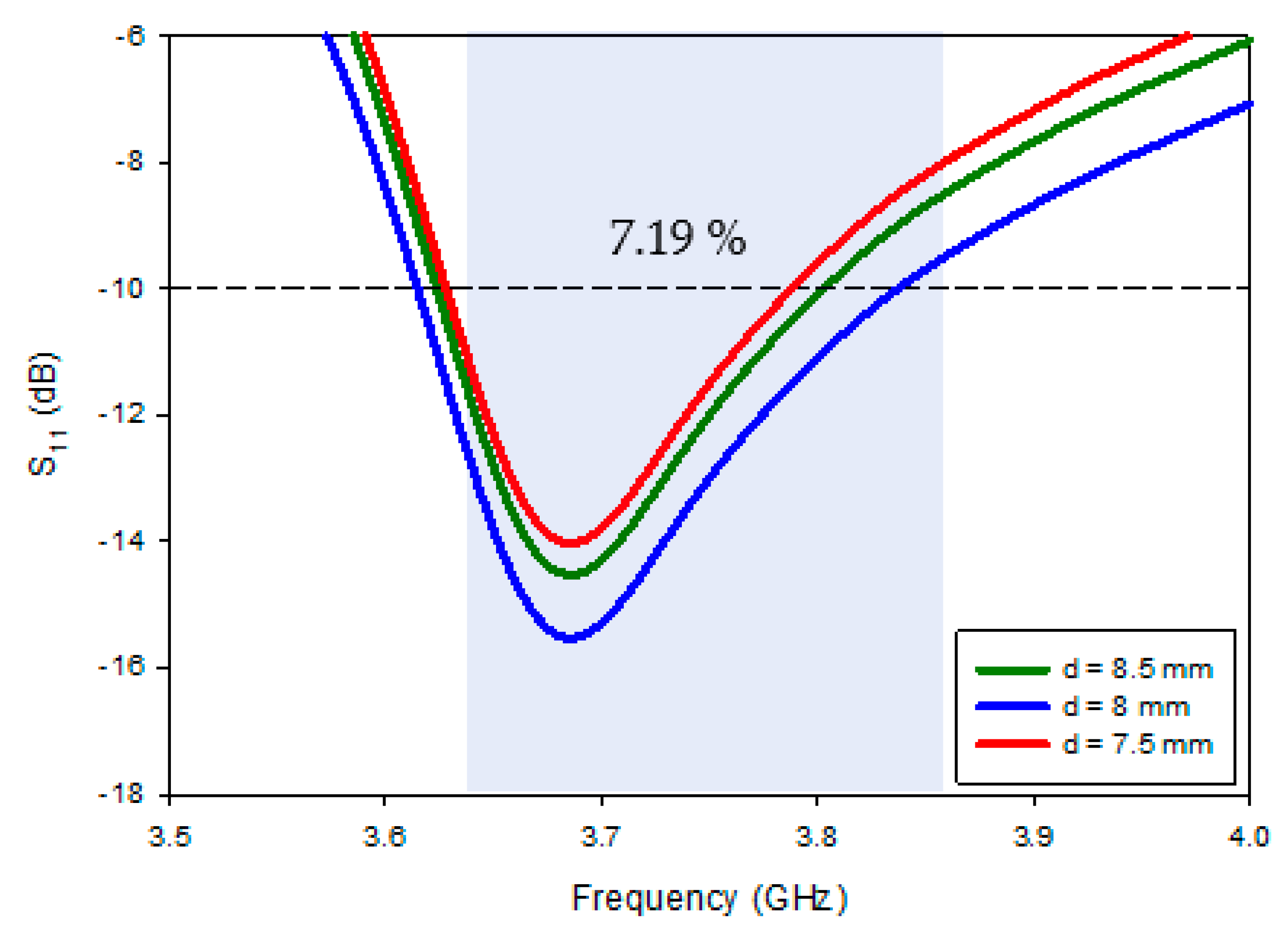
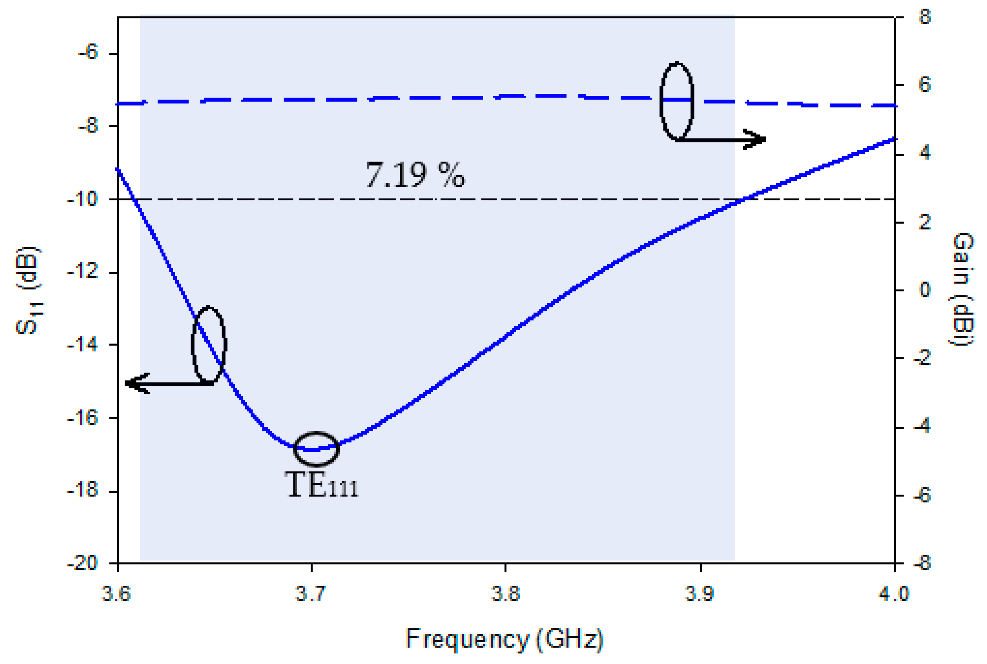
3. Impedance Matching and 3-dB Axial Ratio Bandwidth Improving Operation

As clear from Figure 6, Cross shape feed produces a relatively narrow Impedance matching and 3-dB Axial ratio bandwidths. To tackle the issue, some modification has been made as shown in Figure 2d, in the new modification a metal plate working like a parasitic patch is introduced at top of the RDRA at an optimized location with optimized parameters. In order to keep the asymmetry of the design, The dimension of the parasitic patch on top of the RDRA has the same as other feed lengths. By introducing the parasitic patch on top shows significant improvement in the results.

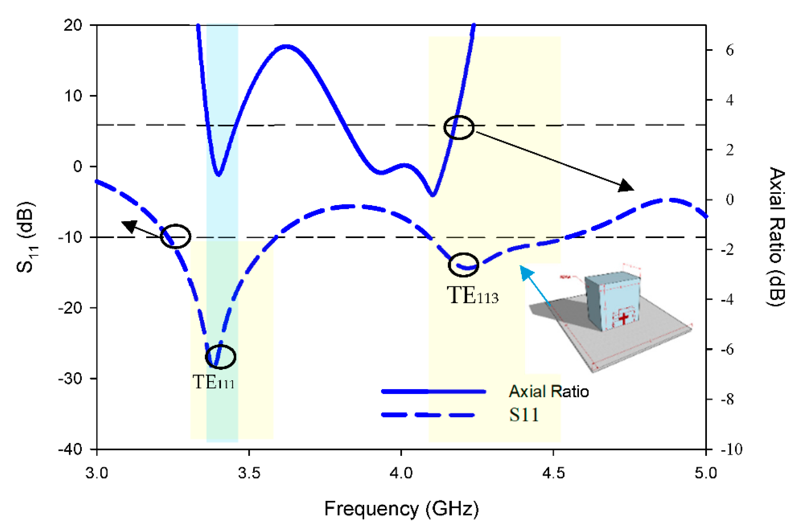
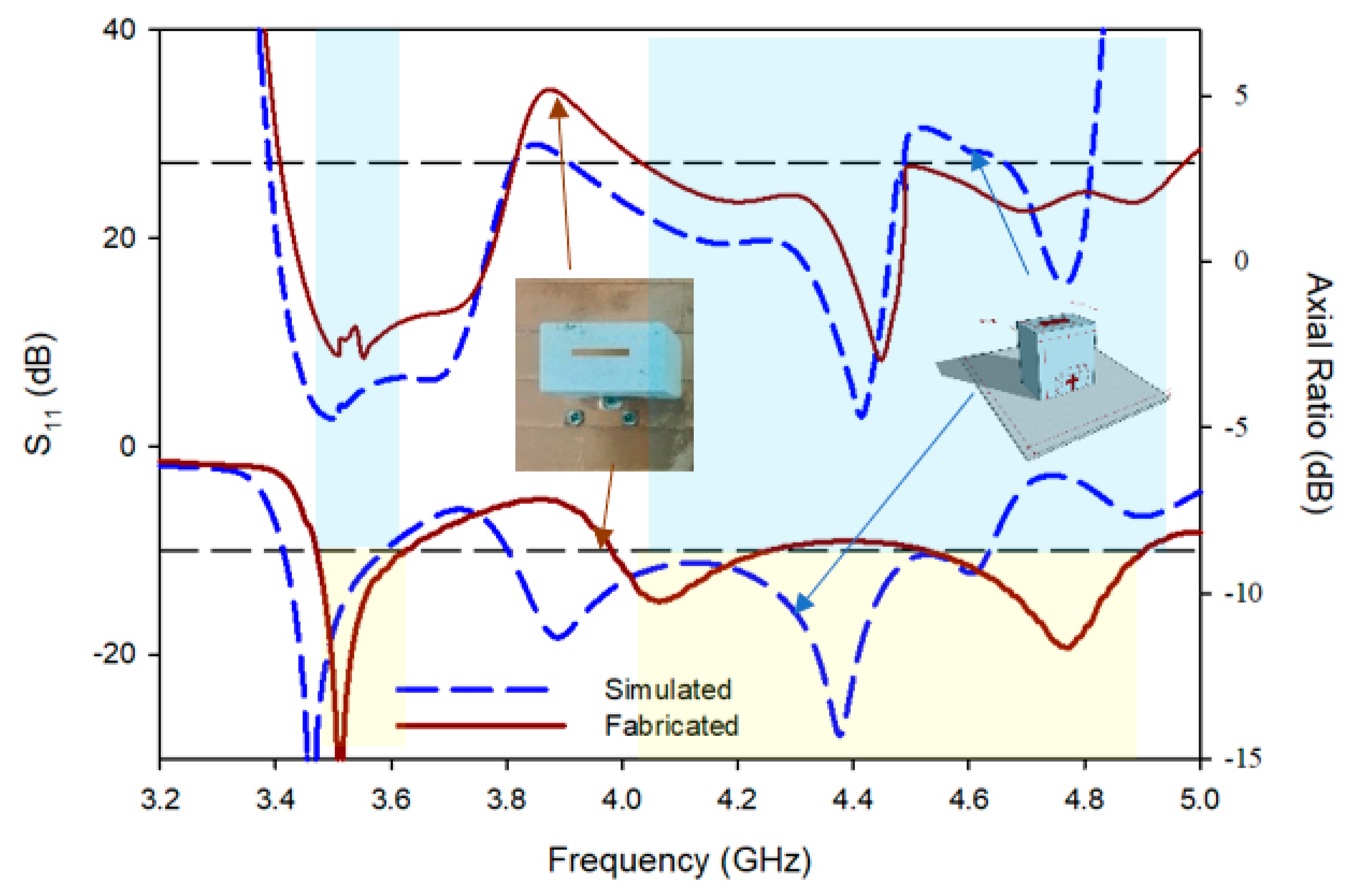
4. Simulated Result of Proposed RDRA

Dual-band radiation of the proposed RDRA has been attained by engendering quasi- 55,111 mode through the single feed, and quasi- TE111 and TE113 mode because of the cross-shaped feed. With the help of a parasitic patch on top of RDRA, Not only is the Impedance matching of two bands improved but so are the CP performances of two bands (particularly the higher band).
At 3.47 GHz and 4.41 GHz, two resonant modes were concurrently excited, as seen in Figure 7. The bands of quasi-TE111 and quasi-TE113 modes can be blended together and a large CP bandwidth is obtained by properly setting the values of l1 and w1 of the floating parasitic patch on top of RDRA. The frequency ratio of fTE113/fTE111 should be close to 1.25 in order to even achieve a wide CP bandwidth in the upper band. Because a small fTE113/fTE111 results in a narrow CP bandwidth in the upper band, a large fTE115/fTE113 results in the upper band splitting into two bands.
The optimized design yielded wide 3 dB bandwidths of 9.0% (1.81–1.98 GHz) and 20.2% (2.40–2.94 GHz) for the lower and upper bands, respectively, as illustrated in Figure 7. Because the proposed antenna contains a conformal metal parasitic patch that plays at the upper band, the CP bandwidth of the lower band is nearly three times the typical 3-dB axial-ratio bandwidth for a regular single-point-fed RDRA working in its fundamental mode. However, because the resonances of DRA and cross-shape feeds are so close, it appears that the lower CP band has only one AR minimum. On the other hand, S11 features are influenced by the length (L) and width (w) of the metallic ground PEC plane as shown in Figure 2a, as well as the gap between the partial ground plane and the DR (G), because this parameter serves as a matching network for the proposed RDRA. The capacitance (C) created by the gap between the conformal metal parasitic strip and the DRA top corner logically balances the proposed RDRA’s inductance (L). As a result, the Q-factor was reduced [8]. This factor plays a significant role in widening the S11 bandwidth. The upper-band impedance was improved in particular, with little effect on lower-band performance.

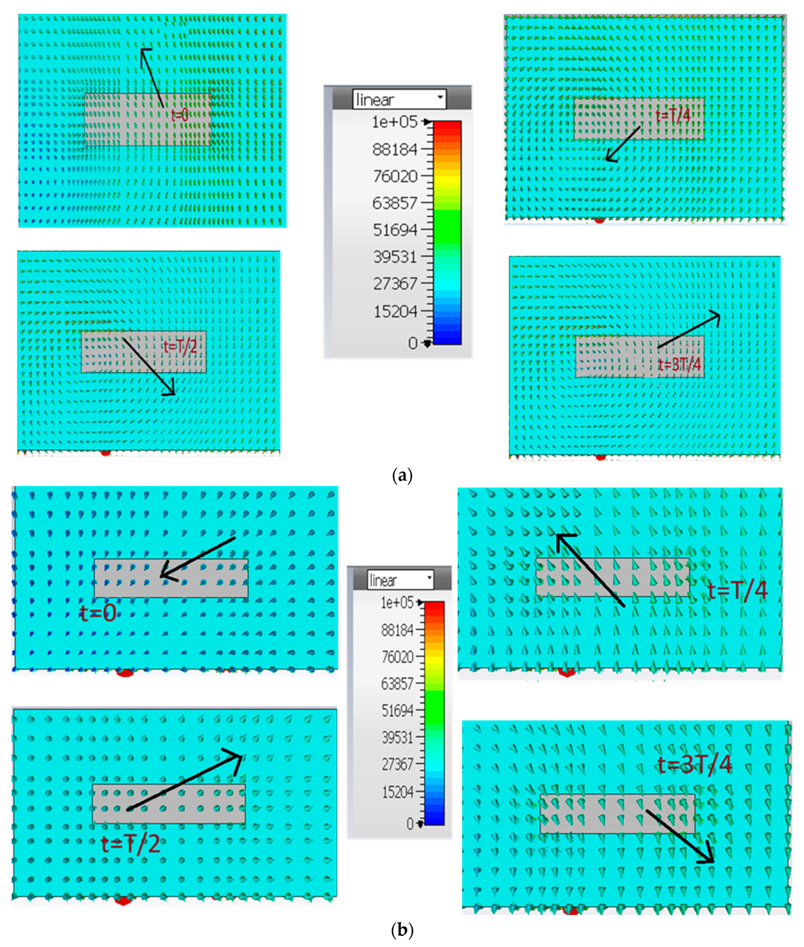
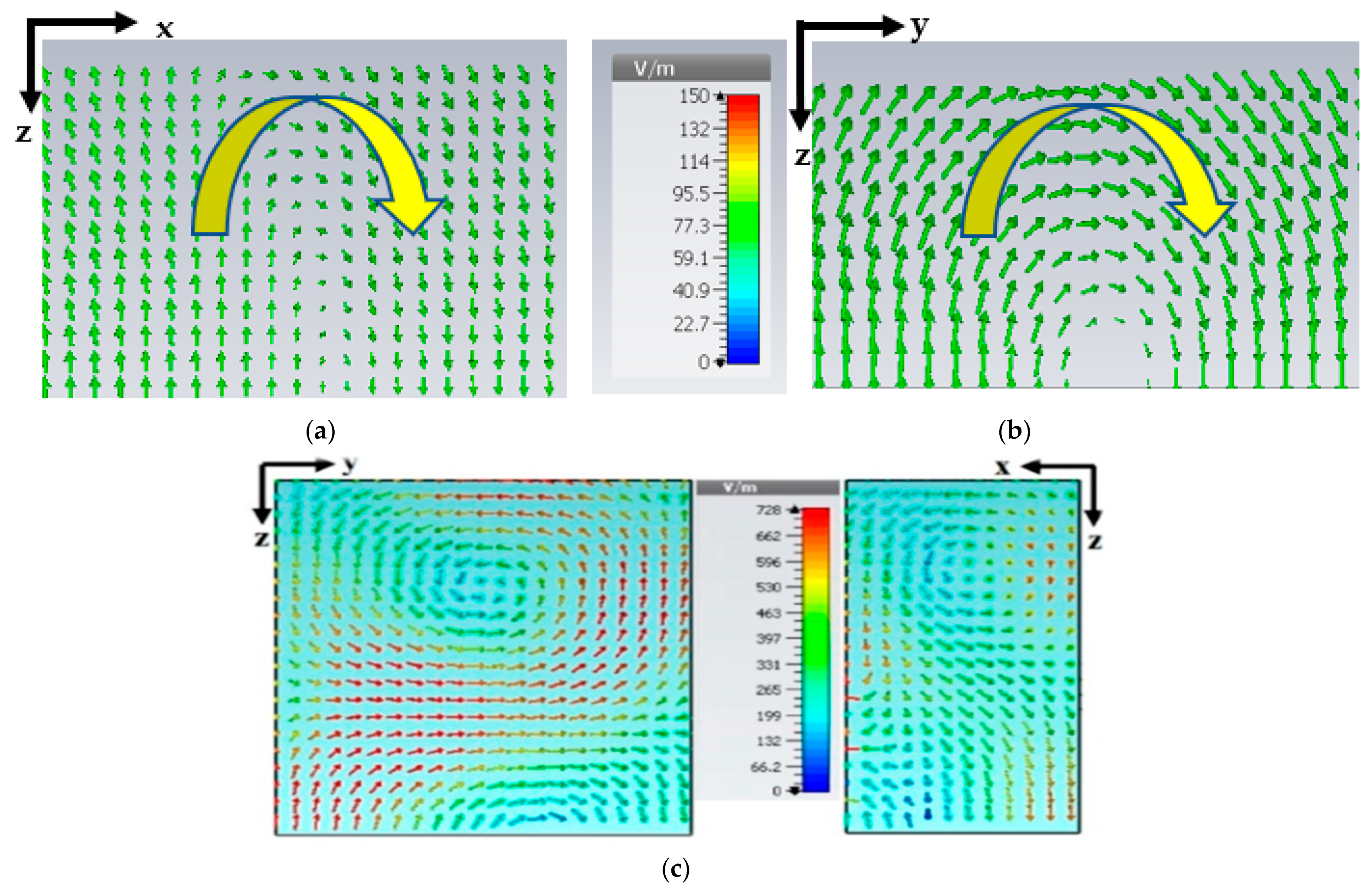
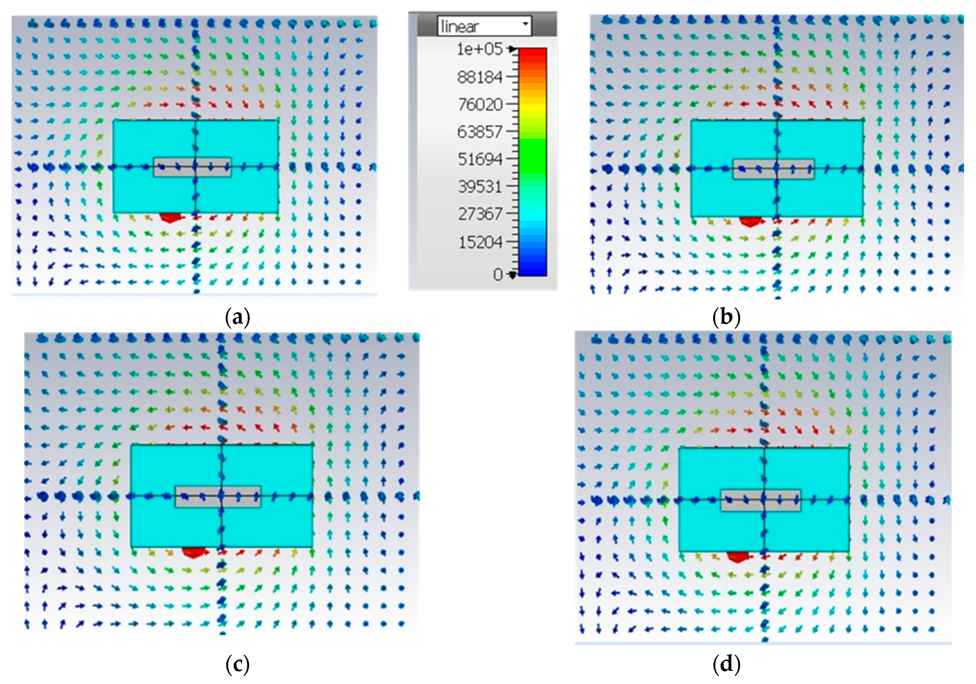
5. E-Field Distributions Because of Parasitic Patch

By assessing the electric field distribution inside the geometry of RDRA using Eigen mode analysis, the parasitic patch feed of RDRA is used to stimulate the orthogonal fields in the suggested RDRA, as shown in Figure 8. The performance of circular polarization is defined by the drive of the electric field within the RDRA at four (4) different phases (t), namely 0°, 90°, 180°, and 270°. The direction of the electric field varies according to phases if the phase angle fluctuates 90° or 180° to 270°, as seen in Figure 7. When the phase shifts from 0° to 180°, the electric field spins in the opposite direction in parallel. Similarly, when the phase changes from 90° to 270°, similar performance is seen. Thus, the given parameters confirmed that the parasitic patch on top is likewise responsible for the creation of CP radiation in the suggested RDRA.
In order to check whether the proposed design excites right-handed circular polarization (RHCP)/left-handed circular polarization (LHCP) or both, again the simulated E-field distributions will be considered. The upper surface of the proposed RDRA is depicted in Figure 9a,b at 3.47 and 4.41 GHz respectively. The different polarity of the radiated CP wave is determined by the rotation of the E-field vectors. Comparing from t = 0 to t = T, the vector of major E-fields at t = T/4 is orthogonal to that at t = 0 and rotates counterclockwise as the time increases, therefore at band 3.47 GHz, producing RHCP fields as shown in Figure 8a.
Similarly, as depicted in Figure 8b 4.41 GHz, clockwise rotation is produced, and an LHCP is generated. Therefore, RHCP and LHCP can be achieved respectively at the two bands, and the dual-band CP antenna is produced. As shown in Table 3, the outcome of the proposed RDRA is relatively better than single and cross-shape feed antennas. It features impedance bandwidths of 6.4% (3.47–3.61 GHz) and 25.26% (4.0–4.90 GHz), and 3-dB AR bandwidths of 12.6% (3.40–3.80 GHz) and 27.82% (4.03–4.97 GHz) in the lower and upper bands, respectively.
Finally, Table 4 tabulates an evaluation of the anticipated RDRA and other formerly claimed dual-CP antennas in the literature. Dual-band and dual-CP antennas have been tabulated in the table below, but mostly have complex structures and complicated techniques to generate CP waves. The proposed antenna offers a solution to the problem. The suggested antenna has the largest AR bandwidth, this distinguishes it from previous dual-band dual-CP systems. Furthermore, the recommended DRA offers an enhanced and flat gain, outperforming previous research. Furthermore, unlike [5,9], the suggested DRA has a simpler architecture with no intricate feeding networks or bulky elements.

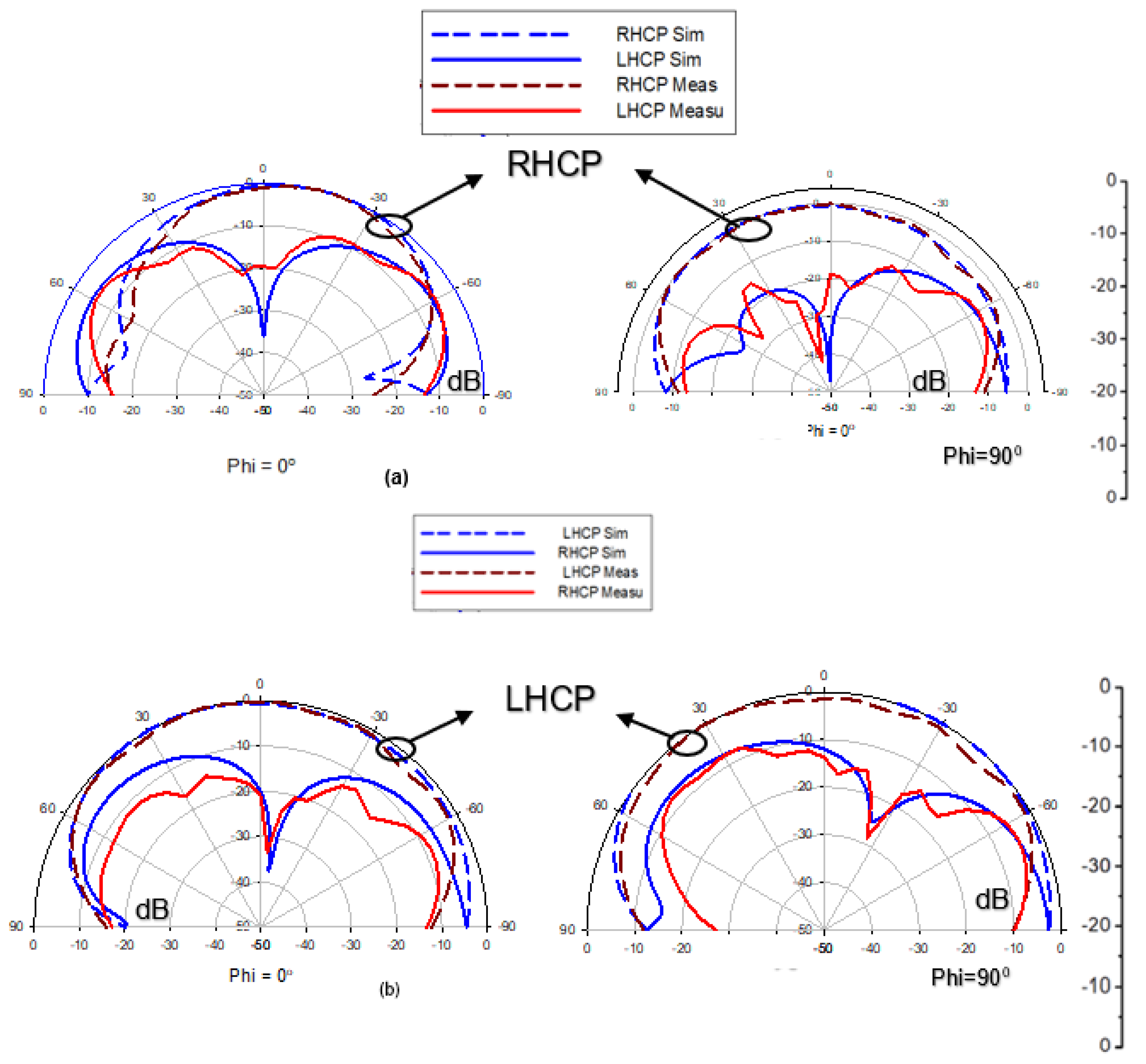
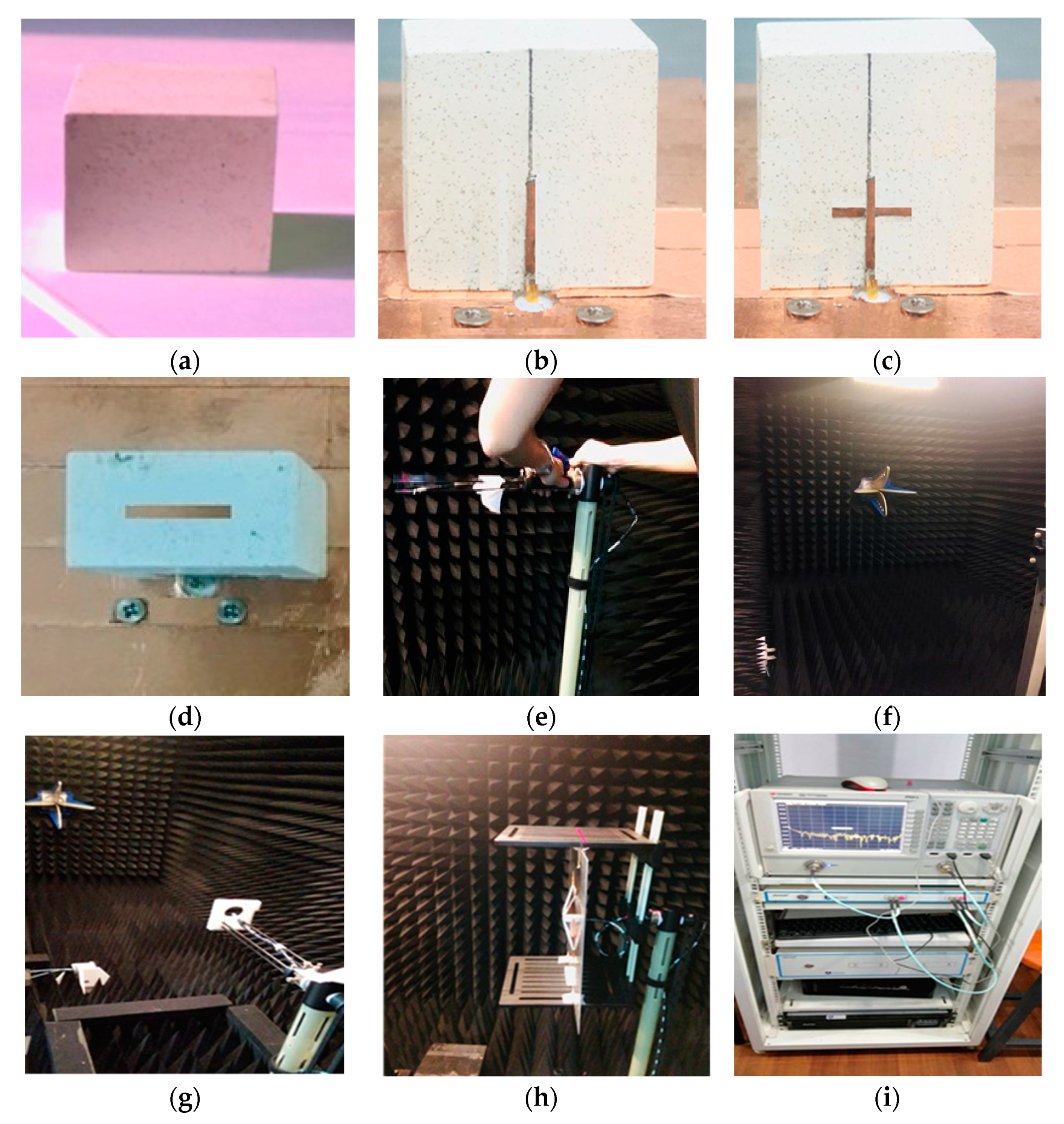
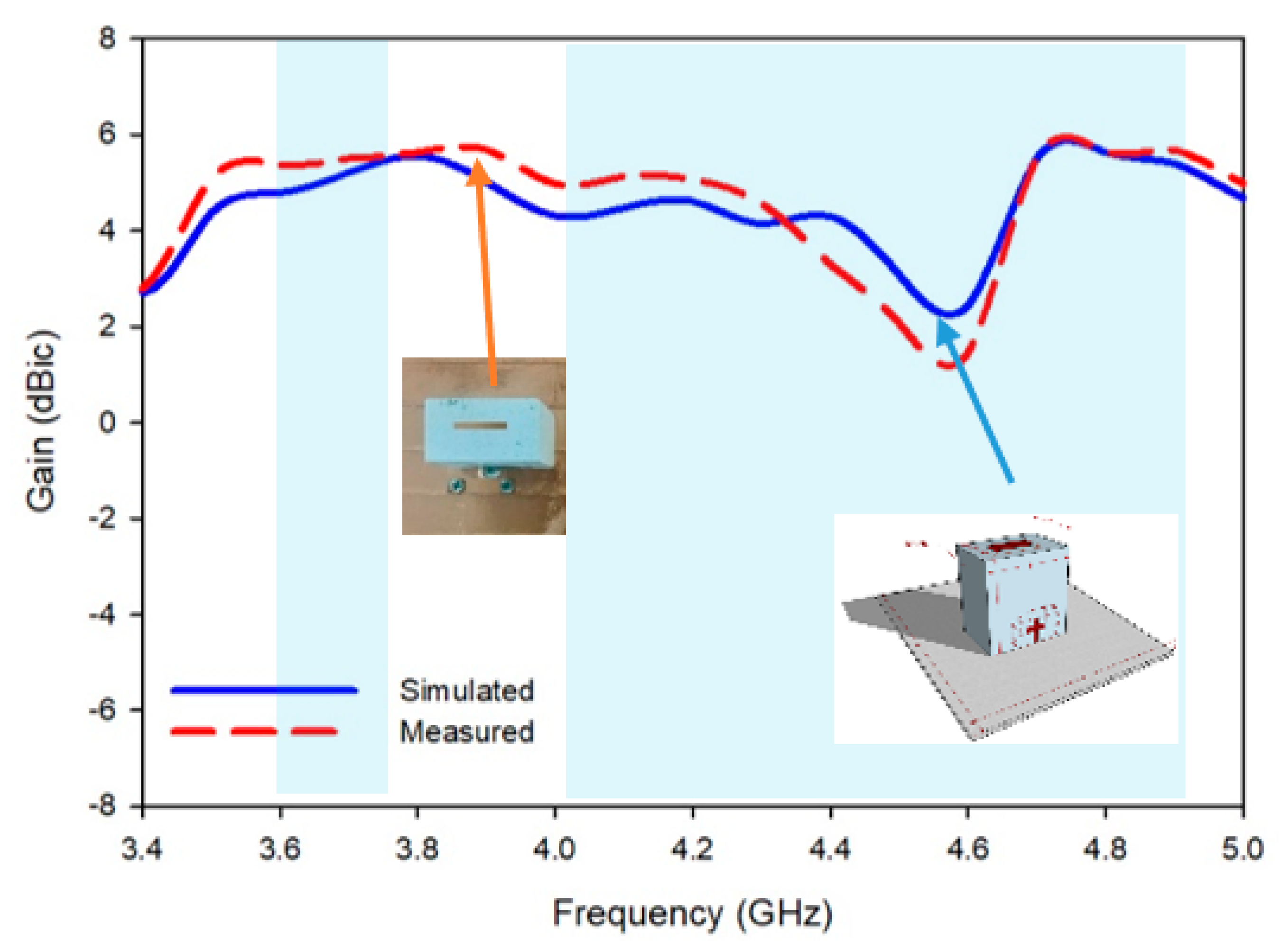
6. Fabrication and Experimental Verification

The dual-band CP with parasitic patch through a single feed mechanism was fabricated and measured. The dielectric resonator is fabricated of Al2O3 ceramic material εdr = 10), which is placed on the PEC ground plane. An agilent network analyzer AV3672E was utilized for quantifying scattering parameters (|S11| measuring), and far-field parameter performance, i.e., AR, radiation pattern, and realized gain was computed by EMT-24 SATIMO measuring system in microwave chamber traditional feeds (probe feed, coaxial, and microstrip, etc.), which have more disadvantages than conformal metal strips, which is why conformal strips can be used to replace them. Coaxial feeding has issues such as air gaps, which create frequency irregularities. On the other hand, conformal strips may be simply glued to the SMA connector’s coaxial feed line [21]. Furthermore, conformal strips eliminate air gaps since they are constructed of conductive adhesive copper tape that adheres to the DRA wall quickly and tightly. Figure 10 illustrates the measured and simulated return loss and AR of the suggested RDRA. The measured return loss bandwidths are 6.4% (3.47–3.61 GHz) and 22.26% (4.0–4.90 GHz), respectively. While on the other hand, the proposed antenna has an extra advantage of dual-band circular polarization. For the measurement, the dual-liner pattern method was used to the measured 3-dB AR bandwidths of the proposed antenna. It can be concluded from Figure 10 that the 3-dB axial ratio bandwidth (measured) of the proposed antenna in the lower and upper-frequency band is about 12.6% (3.40–3.95 GHz) and 27.82% (4.03–4.97 GHz) respectively. It has been observed that floating metal strips had less of an impact on measured antenna performance, and the results matched the predictions.
The main reason for the disparity in performance between measured and simulated results is higher substrate loss, and reasonable agreement is attained among the simulated and measured results, and the slight discrepancy is mostly triggered by the measurement restrictions and fabrication error. In the zone of 4.4 GHz, the difference in simulated and fabricated frequencies is significant because of the air gap between the conformal metal strip and DRA, which shifts the resonance frequency upward. Pressing the feed may produce the same result as shown in the simulation but removing the finger may cause this issue. It is not possible to put a finger on the feed in an anechoic chamber. The concept will be clear from Figure 11h by using transparent tape to reduce the air gap between RDRA and pec ground plane. However, removing the air between the strip and RDRA is a bit challenging which might be overcome through the double tape (conducting tape for feed) and glue.
A photograph of the fabricated prototype and random pictures of the antenna under test in the anechoic chamber have been portrayed in Figure 11.
Figure 12 depicts the predicted and measured bore-sight gains, demonstrating that a sufficient gain of over 5.95 dBic was achieved over the achievable circular polarization spectrum. The antenna emits CP radiation in two operating bands, with measured realized gains ranging from 5.12 to 5.65 dBic and 2.40 to 5.95 dBic, respectively.
Figure 13 depicts the predicted and measured radiation patterns for two CP modes. In the boresight direction (θ = 0°), the measured RHCP field strength is roughly 15 dB greater than LHCP at 3.47 GHz, as shown in Figure 13. (a). This shows that in the bottom band, the proposed DRA allows for anticlockwise CP wave rotation. Meanwhile, as shown in Figure 13, the measured LHCP field intensity at 4.41 GHz is about 18 dB higher than that of RHCP; (b). This shows that the upper band rotates in a clockwise direction. As a result, the dual-band CP antenna shown here generates directed radiation with low cross-polarizations that are stable.

7. Conclusions

In this research article, a singly-fed dual-band dual circularly polarized DRA was developed. It was observed that a cross shape-conformal metal strip along with a parasitic patch on top of RDRDA was utilized to achieve dual-band dual circularly polarization radiation. Initially, a single strip provided a fairly narrow S11 bandwidth. In order to overcome the issue of narrow bandwidth, a single strip is converted to cross-shape feed. It was observed that through this step not only the impedance bandwidth but also parallel circularly polarized waves were generated. Further, by just deploying a parasitic metallic strip on top of the RDRA at an optimized location, the antenna exhibited a very broad10-dB impedance operation at the lower band with 6.4% (3.47–3.61 GHz) and 22.26% (4.0–4.90 GHz) with the upper band, respectively, while on the other hand, the measured 3-dB AR bandwidths are 12.6% (3.40–3.95 GHz) and 27.82% (4.03–4.97 GHz) in the lower and upper bands, respectively. Because the proposed wideband CP DRA has a simple structure, feeding mechanism, stable gain, and radiation patterns, it is a good candidate for wireless applications.

Author Contributions

Conceptualization, J.I., U.I., A.R., H.A., M.A. and M.D.; methodology, E.M.A., U.I., H.A., M.A. and M.D.; software, U.I. and H.A.; validation, E.M.A., M.A. and M.D.; formal analysis, E.M.A., M.A. and M.D.; investigation, E.M.A., M.A. and M.D.; resources, M.A.K. (Muhammad Amir Khan) and H.A.; data curation, I.B., U.I. and H.A.; writing—original draft preparation, M.A.K. (Muhammad Abbas Khan), E.M.A., A.R. and H.A.; writing—review and editing, M.A.K. (Muhammad Abbas Khan), J.I., A.R., U.I., H.A., M.A. and M.D.; visualization, J.I. and E.M.A.; supervision, I.B., M.A. and M.D.; project administration, I.B. and H.A.; funding acquisition, M.A. and M.D. All authors have read and agreed to the published version of the manuscript.

Funding

This project has received funding from the Universidad Carlos III de Madrid and the European Union’s Horizon 2020 research and innovation programme under the Marie Sklodowska-Curie Grant 801538.

Institutional Review Board Statement

Not applicable.

Informed Consent Statement

No applicable.

Data Availability Statement

All Data has been included in study.

Acknowledgments

The authors sincerely appreciate the support from the Universidad Carlos III de Madrid and the European Union’s Horizon 2020 research and innovation programme under the Marie Sklodowska-Curie Grant 801538.

Conflicts of Interest

The authors declare no conflict of interest.

References

  1. Chen, H.-D.; Tsai, Y.-C.; Sim, C.-Y.-D.; Kuo, C. Broadband Eight-Antenna Array Design for Sub-6 GHz 5G NR Bands Metal-Frame Smartphone Applications. IEEE Antennas Wirel. Propag. Lett. 2020, 19, 1078–1082. [Google Scholar] [CrossRef]
  2. Jha, K.R.; Jibran, Z.A.P.; Singh, C.; Sharma, S.K. 4-Port MIMO Antenna Using Common Radiator on a Flexible Substrate for Sub-1GHz, Sub-6GHz 5G NR, and Wi-Fi 6 Applications. IEEE Open J. Antennas Propag. 2021, 2, 689–701. [Google Scholar] [CrossRef]
  3. Zhou, Y.; Jiao, Y.; Weng, Z.; Ni, T. A Novel Single-Fed Wide Dual-Band Circularly polarized Dielectric Resonator Antenna. IEEE Antennas Wirel. Propag. Lett. 2016, 15, 930–933. [Google Scholar] [CrossRef]
  4. Kiani, S.H.; Altaf, A.; Abdullah, M.; Muhammad, F.; Shoaib, N.; Anjum, M.R.; Damaševičius, R.; Blažauskas, T. Eight element side edged framed MIMO antenna array for future 5G smart phones. Micromachines 2020, 11, 956. [Google Scholar] [CrossRef] [PubMed]
  5. Lin, K.Z.; Wu, T.T. Dual-band circularly polarized hybrid dielectric resonator antenna with gain enhancement. AEU—Int. J. Electron. Commun. 2022, 146, 154121, ISSN 1434-8411. [Google Scholar] [CrossRef]
  6. Kiani, S.H.; Altaf, A.; Anjum, M.R.; Afridi, S.; Arain, Z.A.; Anwar, S.; Khan, S.; Alibakhshikenari, M.; Lalbakhsh, A.; Khan, M.A.; et al. Mimo antenna system for modern 5g handheld devices with healthcare and high rate delivery. Sensors 2021, 21, 7415. [Google Scholar] [CrossRef] [PubMed]
  7. Gupta, A.; Gangwar, R.K. Dual-Band Circularly polarized Aperture Coupled Rectangular Dielectric Resonator Antenna for Wireless Applications. IEEE Access 2018, 6, 11388–11396. [Google Scholar] [CrossRef]
  8. Xu, H.; Chen, Z.; Liu, H.; Chang, L.; Huang, T.; Ye, S.; Zhang, L.; Du, C. Single-Fed Dual-Circularly polarized Stacked Dielectric Resonator Antenna for K/Ka-Band UAV Satellite Communications. IEEE Trans. Veh. Technol. 2022, 71, 4449–4453. [Google Scholar] [CrossRef]
  9. Keyrouz, S.; Caratelli, D. Dielectric Resonator Antennas: Basic Concepts, Design Guidelines, and Recent Developments at Millimeter-Wave Frequencies. Int. J. Antennas Propag. 2016, 2016, 6075680. [Google Scholar] [CrossRef]
  10. Serghiou, D.; Khalily, M.; Singh, V.; Araghi, A.; Tafazolli, R. Sub-6 GHz Dual-Band 8 × 8 MIMO Antenna for 5G Smartphones. IEEE Antennas Wirel. Propag. Lett. 2020, 19, 1546–1550. [Google Scholar] [CrossRef]
  11. Illahi, U.; Iqbal, J.; Sulaiman, M.I.; Alam, M.; Su’ud, M.M.; Khattak, M.I. Design and development of a singly-fed circularly polarized rectangular dielectric resonator antenna for WiMAX/Satellite/5G NR band applications. AEU 2020, 126, 153443. [Google Scholar] [CrossRef]
  12. Petosa, A. Dielectric Resonator Antenna Handbook; Artech House: Norwood, MA, USA, 2007. [Google Scholar]
  13. Leung, K.W.; Wong, W.C.; Luk, K.M.; Yung, E.K.N. ‘Circular-polarised dielectric resonator antenna excited by dual conformal strips. Electron. Lett. 2000, 36, 484–486. [Google Scholar] [CrossRef]
  14. Wang, X.-C.; Sun, L.; Lu, X.-L.; Liang, S.; Lu, W.-Z. Single-feed dual-band circularly polarized dielectric resonator antenna for CNSS applications. IEEE Trans. Antennas Propag. 2017, 65, 4283–4287. [Google Scholar] [CrossRef]
  15. Fakhte, S.; Oraizi, H.; Karimian, R.; Fakhte, R. A new wideband cir-cularly polarized stair-shaped dielectric resonator antenna. IEEE Trans. Antennas Propag. 2015, 63, 1828–1832. [Google Scholar] [CrossRef]
  16. Wang, K.X.; Wong, H. A circularly polarized antenna by using rotated-stair dielectric resonator. IEEE Antennas Wirel. Propag. Lett. 2015, 14, 787–790. [Google Scholar] [CrossRef]
  17. Fang, X.S.; Leung, K.W.; Lim, E.H.; Chen, R.S. Compact differential rectangular dielectric resonator antenna. IEEE Antennas Wirel. Propag. Lett. 2010, 9, 662–665. [Google Scholar] [CrossRef]
  18. Long, R.T.; Dorris, R.J.; Long, S.A.; Khayat, M.A.; Williams, J.T. Use of parasitic strip to produce circular polarisation and increased bandwidth for cylindrical dielectric resonator antenna. Electron. Lett. 2001, 37, 406–408. [Google Scholar] [CrossRef]
  19. Leung, K.W.; Ng, H.K. Theory and experiment of circularly polarized dielectric resonator antenna with a parasitic patch. IEEE Trans. Antennas Propag. 2003, 51, 405–412. [Google Scholar] [CrossRef]
  20. Leung, K.W. Conformal strip excitation of dielectric resonator antenna. IEEE Trans. Antennas Propag. 2000, 48, 961–967. [Google Scholar] [CrossRef]
  21. Li, R.; Dejean, G.; Laskar, J.; Tentzeris, M.M. Investigation of circularly polarized loop antennas with a parasitic element for band-width enhancement. IEEE Trans. Antennas Propag. 2005, 53, 3930–3939. [Google Scholar]
  22. Sulaiman, M.I.; Khamas, S.K. A singly fed wideband circularly polarized dielectric resonator antenna using concentric open half-loops. IEEE Antennas Wirel. Propag. Lett. 2011, 10, 1305–1308. [Google Scholar] [CrossRef]
  23. Abedian, M.; Rahim, S.K.A.; Danesh, S.; Jamaluddin, M.H.; Islam, M.T. Compact wideband circularly polarised dielectric resonator antenna. Electron. Lett. 2016, 53, 5–6. [Google Scholar] [CrossRef]
  24. CST Reference Manual, Comput. Simul. Technol., Darmstadt, Germany. 2017. Available online: https://www.microwavejournal.com/authors/2519-ansys-canonsburg-pa (accessed on 2 April 2022).
  25. Li, B.; Leung, K.W. Strip-fed rectangular dielectric resonator antennas with/without a parasitic patch. IEEE Trans. Antennas Propag. 2005, 53, 2200–2207. [Google Scholar]
  26. Lim, E.H.; Leung, K.W.; Fang, X. The compact circularly-polarized hollow rectangular dielectric resonator antenna with an underlaid quadrature coupler. IEEE Trans. Antennas Propag. 2010, 59, 288–293. [Google Scholar] [CrossRef]
  27. Iqbal, J.; Illahi, U.; Sulaiman, M.I.; Alam, M.M.; Su’ud, M.M.; Yasin, M.N.M. Mutual coupling reduction using hybrid technique in wideband circularly polarized MIMO antenna for WiMAX applications. IEEE Access 2019, 7, 40951–40958. [Google Scholar] [CrossRef]
  28. Fang, X.; Leung, K.W.; Lim, E.H. Singly-fed dual-band circularly polarized dielectric resonator antenna. IEEE Antennas Wirel. Propag. Lett. 2014, 13, 995–998. [Google Scholar] [CrossRef]
  29. Mongia, R. Theoretical and experimental resonant frequencies of rectangular dielectric resonators. IEE Proc. H (Microw. Antennas Propag.) 1992, 139, 98–104. [Google Scholar] [CrossRef]
  30. Abdulmajid, A.A.; Khalil, Y.; Khamas, S. Higher-order-mode cir-cularly polarized two-layer rectangular dielectric resonator antenna. IEEE Antenna Wirel. Propag. Lett. 2018, 17, 1114–1117. [Google Scholar] [CrossRef]
  31. Alieldin, A.; Huang, Y.; Stanley, M.; Joseph, S.D.; Lei, D. A 5G MIMO Antenna for Broadcast and Traffic Communication Topologies Based on Pseudo Inverse Synthesis. IEEE Access 2018, 6, 65935–65944. [Google Scholar] [CrossRef]
  32. Huang, H.; Li, X.; Liu, Y. 5G MIMO Antenna Based on Vector Synthetic Mechanism. IEEE Antennas Wirel. Propag. Lett. 2018, 17, 1052–1055. [Google Scholar] [CrossRef]
  33. Sim, C.-Y.-D.; Chen, H.-D.; Kulkarni, J.; Lo, J.-J.; Hsuan, Y.-C. Recent Designs to Achieving Wideband MIMO Antenna for 5G NR Sub-6GHz Smartphone Applications. In Proceedings of the 2020 International Symposium on Antennas and Propagation (ISAP), Osaka, Japan, 25–28 January 2021; pp. 417–418. [Google Scholar] [CrossRef]
  34. Das, G.; Sharma, A.; Gangwar, R.; Sharawi, M. Compact Back to Back DRA Based Four Port MIMO Antenna System with Bi-directional Diversity. Electron. Lett. 2018, 54, 884–886. [Google Scholar] [CrossRef]
Figure 1. The geometry of the singly fed RDRA (3-D View) 5G Sub6GHz Applications.
Applsci 12 05222 g001
Figure 2. Evolution of the RDRA (3-D View) (a) Simple RDRA, (b) Linear polarized DRA, (c) circularly polarized RDRA, (d) desired RDRA.
Applsci 12 05222 g002
Figure 3. Reflection coefficients of the RDRA feed at various distances.
Applsci 12 05222 g003
Figure 4. Simulated S-parameter and Gain of the single unit of linearly polarized RDRA.
Applsci 12 05222 g004
Figure 5. E-field distributions of RDRA designs in fundamental modes single feed (a) TE111 at 3.7 GHz. (b) cross shape TE111 at 3.41 GHz. (c) cross shaped-higher-order mode (TE113) at 4.20 GHz.
Applsci 12 05222 g005
Figure 6. Simulated S-parameter and Axial ratio of the cross-shaped RDRA.
Applsci 12 05222 g006
Figure 7. Simulated S-parameter and Axial ratio of the proposed RDRA.
Applsci 12 05222 g007
Figure 8. Electric field distribution inside the proposed design (a), Phase 00, (b), Phase 90° (c), Phase 180° (d) Phase 270°(by using Eigen mode analysis in CST-MWS).
Applsci 12 05222 g008
Figure 9. Simulated E-field distributions on the top view of proposed RDRA at various times. (a) RHCP at 3.47 GHz. (b) LHCP at 4.41 GHz.
Applsci 12 05222 g009
Figure 10. Simulated and Fabricated results of S11 and the axial ratio of proposed RDRA.
Applsci 12 05222 g010
Figure 11. Fabricated Antenna and pics from the chamber. (a) Simple RDRA, (b) single strip, (c) cross-shape feed, (d) top view of proposed RDRA with floating parasitic patch, (eh) AUT in the chamber, and (i) VNA.
Applsci 12 05222 g011
Figure 12. Simulated and measured gain over both bands.
Applsci 12 05222 g012
Figure 13. Radiation pattern of the rectangular DRA at 3.47 GHz and 4.41 GHz at Phi = 0° and phi = 90°.
Applsci 12 05222 g013
Table 1. Dimensions of the RDRA (UNIT: mm).
ParameterDimension
H26.1
B25.4
C14.3
Table 2. Optimization of the feeding strips’ dimensions. (UNIT: mm).
h1b110-B S11 Bandwidth (%)
10.750.55.43
5.18
0.755.92
4.65
4.69
4.92
5.17
5.42
5.96
6.23
6.58
11.7516.89
7.19
7.01
6.75
6.51
1.54.90
12.751.754.42
4.20
3.97
3.75
3.54
23.34
5.91
Table 3. Performance of all antennas (frequency unit: GHz).
Antenna (RDRA)Lower-Band
BW
(|S11| < −10 dB)
Upper-Band
BW
(|S11| < −10 dB)
Lower-Band
3-dB ARBW
Upper-Band
3-dB ARBW
Single feed7.99%000
Cross-shape feed5.2%19.2%12%24.63%
Proposed RDRA6.4%25.26%12.6%27.82%
Table 4. Comparison between the proposed Antenna and other Antennas (Dual CP) (Frequency unit: GHz).
RefDRA ShapeCP TechLower-Band
3-dB ARBW
(%)
Upper-Band
3-dB ARBW
(%)
Single Fed
Dual Band
Dual CP
Structure
[3]CDRAA Pair Of Symmetrical Notches Are
Carved Out From The Cylindrical Dra
15.85.02NoComplicated
[5]Hybrid
DRA
DRA Corners Along The Diagonal Are Cut Off From The Rectangular DRA.2021YESComplicated
[7]RDRAParasitic patch/Triangular Ring shape aperture2.293.04YESSimple
[8]RDRAMulti layering/metallic strip on top5.24.1YESComplicated
[9]FSSFSS-Integrated Polarization Rotation AMC2.44.8YESComplicated
Proposed RDRARDRACross-shape/Floating parasitic metallic patch on top12.627.82YESSimple
Publisher’s Note: MDPI stays neutral with regard to jurisdictional claims in published maps and institutional affiliations.

