Article

On the Effects of Disc Deformation on the Tilting-Induced Vibration of a Spline-Guided Spinning Disc with an Axial-Fixed Boundary

1
School of Mechanical Engineering, Beijing Institute of Technology, Beijing 100811, China
2
Key Laboratory of Science and Technology for National Defense, Beijing Institute of Technology, Beijing 100811, China
*
Author to whom correspondence should be addressed.
Appl. Sci. 2022, 12(7), 3637; https://doi.org/10.3390/app12073637
Submission received: 21 February 2022 / Revised: 29 March 2022 / Accepted: 30 March 2022 / Published: 4 April 2022

Abstract

:
This paper investigates the effects of disc deformation on the tilting-induced vibration of a splined spinning disc with axial-fixed boundaries.The purpose is to provide an intuitive interpretation of the vibration variance of the wet clutch system with different deformed discs. First, tilting models of flat and deformed discs are derived by introducing distinctive shape functions. Additionally, the inner spline interface is chosen as the friction boundary. Then, an impact model between friction pairs and the rigid boundary is established by adopting Hertz’s contact theory. Finally, the dynamic equations are solved via numerical methods, and the responses are analyzed in both time and frequency domains. The deformation can increase the nonlinearity of the dynamic response of the spinning disc. Moreover, the effects of increasing the impulse force and reducing the boundary distance are quite similar; they both increase the motion intensity.

1. Introduction

The dynamic characteristics of spinning spline-guided discs have drawn much attention in recent years [1]. Understanding the topic is important for improving equipment reliability in relevant engineering fields, such as the wet clutch [2]. However, during the operation of such equipment, permanent deformation can occur in some discs. Figure 1 shows two common types of disc buckling; such deformation usually degrades the performance of the equipment [3]. A specific example was presented by Cui et al. [4], who investigated the oil flow between deformed friction discs in a transmission system and found that viscous torque increased due to the deformation of the friction pairs. On the other hand, the clutch disc wobbling occurs during wet clutches [5], and deformation of those discs could affect the vibration signal of the wet clutch system [6]. In other words, the dynamic difference between deformed discs and flat discs can be used for fault diagnosis of the wet clutch, but the underlying mechanism needs to be solved first [7]. Therefore, one particular interest of this work is to investigate the influence of disc deformation on the vibration characteristics of the wet clutch, but starting with a single disc with two fixed boundary rather than multi-disc system.
There have been many studies on the vibration of spline-guided flat discs concerning rigid body effects. Jeong and Bogy [8] measured the rigid-body displacement and deformation as a spinning disk is loaded by a read–write pin. Chen and Bogy [9] determined the natural frequency of a spinning disc with a load system. They also [10] analyzed the effects of rigid-body tilting on the spinning stability. Their work proved the importance of centrifugal force in stabilizing the system and showed that the system stability could be improved by allowing the disc to tilt. Pei et al. investigated the dynamic response of a rotating disk subjected to a reciprocating angular movement [11] and suspension-moving load with an initial runout [12]. The response amplitude increases as the spinning speed is close to the resonance speed of the rotating flexible disk with a stationary loading system, and parametric instability can be suppressed by operating the system at low-frequency and small-amplitude reciprocating external forces. Li et al. [13] investigated the vortex-induced vibration of elastically supported disk, the analysis shows the vibration of the trajectory mode is related to disc vibration. Findlin et al. [14] developed a wobbling model of spinning friction discs and pointed out that the threshold of instability is determined by damping and friction-induced circulation. Yang et al. [15] studied dynamics of rotating disc and shaft system, by taking into account the shaft deformation, they investigated the coupling vibration response of the system. Miyasato et al. [16] modeled the rotating and contact motion of a rigid disc considering the viscous damping on the edge, and the results indicated that edge friction increased the nonlinearity of the coupling motion between rotating and moving.
Compared to conventional annular discs, less attention has been given to the dynamics of deformed discs. Cheng et al. [17] investigated the effects of eccentricity of the central hole on the frequencies and mode shapes. A similar problem was discussed by Maretic [18], who examined the impact of angular speed and eccentricity on the transverse vibration frequencies of the circular plate. Carpino [19] analyzed the effect of initial runout on the dynamics of spinning disks; he assumed an initial curvature for the spinning disk and studied its impact on the dynamics of a spinning disk near a rigid surface. Khorasany and Hutton [20,21] studied the effect of an unsymmetrical initial runout on the oscillation frequencies and the critical speeds of the spinning disks, and the results showed that the natural frequencies of the disks with runout increase in the rotating frame.
The discs driven by the spline shaft have different characteristics from those of free and clamped boundaries. Olver et al. [22] investigated the contact mechanics of a spline coupling, and their work showed that during shaft rotation, most friction regimes encountered gross slip, and only two out of nine cases were stick–slip regimes. Ahmad and Hutton [23] analyzed the critical speed for a spinning disc subjected to an external force with spline constraints, and the spline force was modeled as an elastic spring force. They [24] also analyzed the effect of in-plane edge load on spinning discs and found that spline-guided discs did not undergo merge-type effects or flutter and therefore were more stable than clamped discs at a minor critical speed. In addition, this study requires knowledge to model the impact force between the tilting disc and the boundary. Zhang et al. [25] established a rubbing-impact model between clutch discs, adopted the Hertz contact model and successfully predicted the experimental drag torque of a wet clutch. The contact model and coefficients of the present work simply refer to the preceding works [26,27].
The rest of the paper is arranged as follows: Section 2 starts with the coordinate definition of the spinning discs. Then, Section 2.1 analyzes the tilting moment of the flat disc due to centrifugal force. On this basis, Section 2.2 derives the centrifugal moment of the deformed disc by introducing shape functions. The boundary impact and spline friction are introduced in Section 2.3 and Section 2.4, respectively. In Section 3, the nonlinear responses are simulated via the state space method, and the dynamic characteristics of the discs with different deformation angles are compared. Moreover, the impacts of the impulse force, boundary distance and rotation speed are also analyzed. The conclusions are drawn in Section 4. One approximation is to treat the inner teeth as a smooth edge, thus simplifying the effect due to the teeth geometry.

2. Model and Formulation

Compared to the clamped boundary, the spline interface allows the disc to move laterally along the shaft and tilt around the disc diameter [2]. Therefore, the spinning plane of the spline-guided disc can be flexible. Figure 2 shows the tilting behavior of a single spinning disc driven by a splined hub. Normally, when there is no continuous external excitation, the disc tilts shortly and aligns vertically. However, a few reasons could cause disc tilting: the disc has an initial angle when the machine starts to rotate, or the spinning disc is subjected to irregular external forces, such as mechanical contact between the parts or nonlinear oil flow in the wet clutch [28].
Figure 3 shows a schematic of a spinning disc with an inner radius a and outer radius b splined to an arbor at an angular velocity of ω . Now, the coordinates include the following: (1) the local coordinate ( o z r θ ) is set at the middle surface of the disc and rotates along with the disc, and its z-axis is always perpendicular to the middle plane of the disc; (2) ( O X Y Z ) is a rotating intermediate frame that represents the rotation field of the spline shaft, and its Z-axis coincides with the rotating center of the shaft; and the (3) space-fixed coordinate system ( X f Y f Z f ). One advantage is that, instead of being expressed by two angles between the X-axis and Y-axis, the tilting angle can be expressed by θ Z , which is the angle between the two vertical axes of coordinate system (1) and coordinate system (2). From the perspective of the local coordinate, the disc exhibits the sole motion of tilting around the θ = 0 ( π ) axis due to external forces and moments.
As the disc rotates, the tilting angle θ Z changes due to external forces and moments. Then, the motion in the fixed coordinate system can be determined by coupling the rotation and local tilting. By setting the disc at the origin of the space-fixed coordinate system, a random point p ( r cos θ , r sin θ , z ) on the disc frame can be transferred into the space-fixed coordinate system by introducing Euler rotation matrices:
X f Y f Z f = R r R t r cos θ r sin θ z
where R t and R r are the rotation matrices due to tilting and shaft spinning, respectively. They are written as:
R r = cos ω t sin ω t 0 sin ω t cos ω t 0 0 0 1 , R t = 1 0 0 0 cos θ Z sin θ Z 0 sin θ Z cos θ Z
As the disc rotates, the angle that rotates around the shaft is ω t , and the space-fixed coordinates of any point during the rotation can be expressed as:
X f Y f Z f = cos ω t sin ω t cos θ Z sin ω t sin θ Z sin ω t cos ω t cos θ Z cos ω t sin θ Z 0 sin θ Z cos θ Z r cos θ r sin θ z
Knowing the space-fixed coordinates of the disc is necessary for model development and is important for calculating the impact force and axial displacement of the disc.

2.1. Flat Spinning Disc

A force analysis is illustrated in Figure 4. The mass of the object is considered, and other forces include the supporting force, spline friction, centrifugal force and external force. As mentioned before, the spline allows the disc to move axially and tilt. Taking the movement of the center point to represent the axial movement of the disc body, the governing equation of the axial displacement can be expressed as:
Z f ¨ = F f s
where F is the external force and f s is the friction force. To analyze the tilting response, the centrifugal force is considered. This force can be split into two parts, as plotted in red, and both parts tend to align the disc into the vertical position. Each spline tooth exerts an in-plane tangential force, and the overall force can be unified as a torque at the inner edge that drives the disc to rotate. Since the discs studied in this paper are rotating at a constant speed, the influence of the spline torque is neglected. Therefore, the governing equation of the tilting response can be written as:
I θ θ Z ¨ = M M t M N M f
where M is the external moment, M t is the centrifugal moment, M N is the impact moment and M f is the spline friction moment. Each moment is discussed in later sections.

2.1.1. Rotation-Induced Alignment Moment

Considering the annular disc shown in Figure 4, as defined earlier, ( r , θ , z ) is the local cylindrical coordinate rotating along the middle plane of the disc. The disc is driven by the spline shaft (Z-axis) at a speed of ω with an inclined angle of θ Z . Neglecting the influence of the thickness, the corresponding centrifugal force of one point can be expressed as [25]:
F i = ρ h m r sin θ cos θ Z r i ω 2
where ω is the rotating speed of the angular velocity of the point with respect to the rotating axial, which equals the rotating speed of the spline shaft. In addition, r i is the distance between the mass point and the rotating axial. The total force can be integrated into a moment that tilts back the inclined angle with respect to the θ = 0 axis. This centrifugal moment of the disc can be written as:
M t = a b 0 2 π ρ h r sin θ cos θ Z ω 2 F i r sin θ l i sin θ Z r d r d θ = π 8 ( b 4 a 4 ) ρ h ω 2 sin 2 θ Z
where l i is the arm of the centrifugal force of the point with respect to the rotating axial and where θ Z is the angle between the arm and the centrifugal force.

2.1.2. Moment of Inertia

First, it is important to recall the definition of the moment inertia for further comparison:
d I θ = r i 2 d m
where r i is the distance of the mass to the axis, and the moment of inertia with respect to the θ = 0 axis is:
I θ = a b 0 2 π ( r sin θ ) 2 ρ h r d r d θ = π 4 ( b 4 a 4 ) ρ h

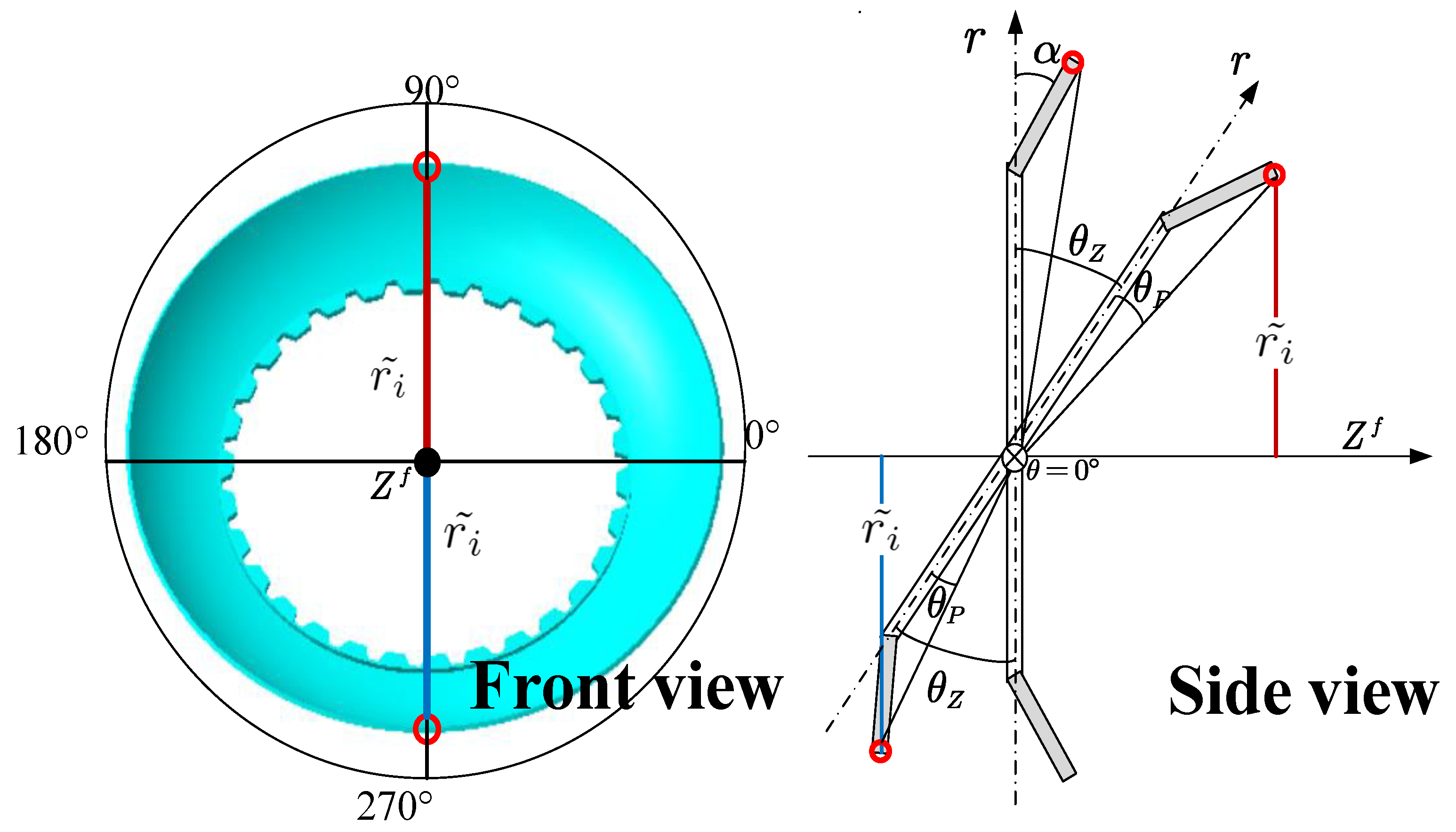
2.2. Formulation of the Deformed Plate

For many spinning discs in transmission systems, especially friction discs, deformation is inevitable and most cases are cone deformation [29]. Therefore, this article only studies the cone deformation. Figure 5 shows the deformed discs, assume that the thickness and the middle plane of the deformed discs are retained as flat discs, and the positive direction of the Z-axis was set at the deformed side of the discs, the deformation function of deformed discs can be expressed as:
w ( r , θ ) = ( r a ) tan α , a < = r < = ( b a ) cos α + a
α is the first-order deformation angle.

2.2.1. Centrifugal Moment of the Deformed Disc

Before calculating the centrifugal force and moment, the deformation-induced angle is defined as:
θ p = arctan w r sin θ
Here, θ p is defined as the angle between the point mass and the tilting axis generated from the deformation. This angle differs from the deformed disc to the flat discs. As explained in Figure 6, the deformation of the disc generates an angle between the selected points and the tilting axis. For instance, when the tilting angle θ Z of the deformed disc is 0, the deformed points still hold an angle to the axis so that the actual is nonzero. Moreover, as the disc tilts, this angle has different impacts on the absolute value of tilting angles: it decreases the tilting angle of upper parts while increasing the value of lower parts. This angle thus causes asymmetry of the centrifugal force of the upper and lower parts. The deformation-induced angle is expressed as a function of local variables and the shape function:
The corresponding centrifugal force of one point of the deformed disc can be expressed as:
F i ˜ = ρ h m ( r sin θ ) 2 + w 2 cos ( θ Z + θ P ) r i ˜ ω 2
This formula has the same mass and angular velocity terms as the flat discs. The new distance between the mass point and the rotating axis is defined as r i ˜ , which accounts for the effect of the deformation. Then, the centrifugal moment of the disc can be written as:
M ˜ t = a ( b a ) cos α + a 0 2 π ρ h m ( r sin θ ) 2 + w 2 cos ( θ Z + θ P ) ω 2 F i ˜ ( r sin θ ) 2 + w 2 l i sin ( θ Z + θ P ) r d r d θ = 1 2 ρ h ω 2 sin ( 2 θ Z ) a ( b a ) cos α + a 0 2 π [ ( r sin θ ) 2 + w 2 ] cos ( 2 θ P ) r d r d θ + 1 2 ρ h ω 2 cos ( 2 θ Z ) a ( b a ) cos α + a 0 2 π [ ( r sin θ ) 2 + w 2 ] sin ( 2 θ P ) r d r d θ
The centrifugal moment after deformation is written in the above form. Since θ P is a function of θ and can be integrated numerically, θ Z can be extracted, so the final form of the centrifugal moment is still a function of the tilting angle θ Z . Note that the upper limit of the integration varies due to deformation. The same change can apply to the moment of inertia.

2.2.2. Moment of Inertia of the Deformed Disc

Taking into account the deformation, the distance between any point of the disc and the rotating axis is now:
r ˜ = ( r sin θ ) 2 + w 2
Thus, the moment inertia of the deformed disc with respect to its tilting axis can be determined as:
I θ ˜ = r i ˜ 2 d m = a ( b a ) cos α + a 0 2 π [ ( r sin θ ) 2 + w 2 ] ρ h r d r d θ
Unlike the case of flat discs, the deformed disc’s moment inertia and centrifugal moment must be integrated numerically.

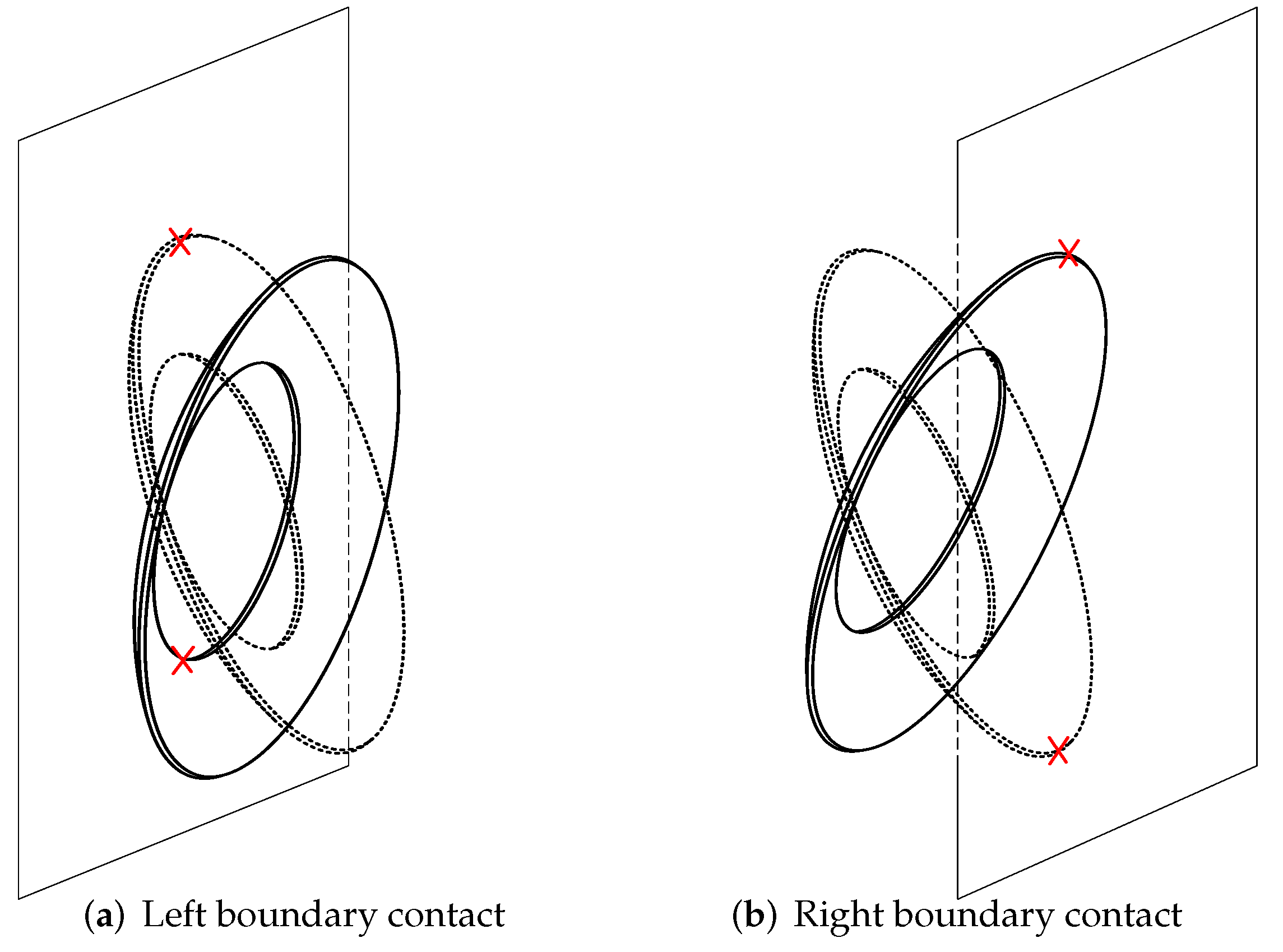
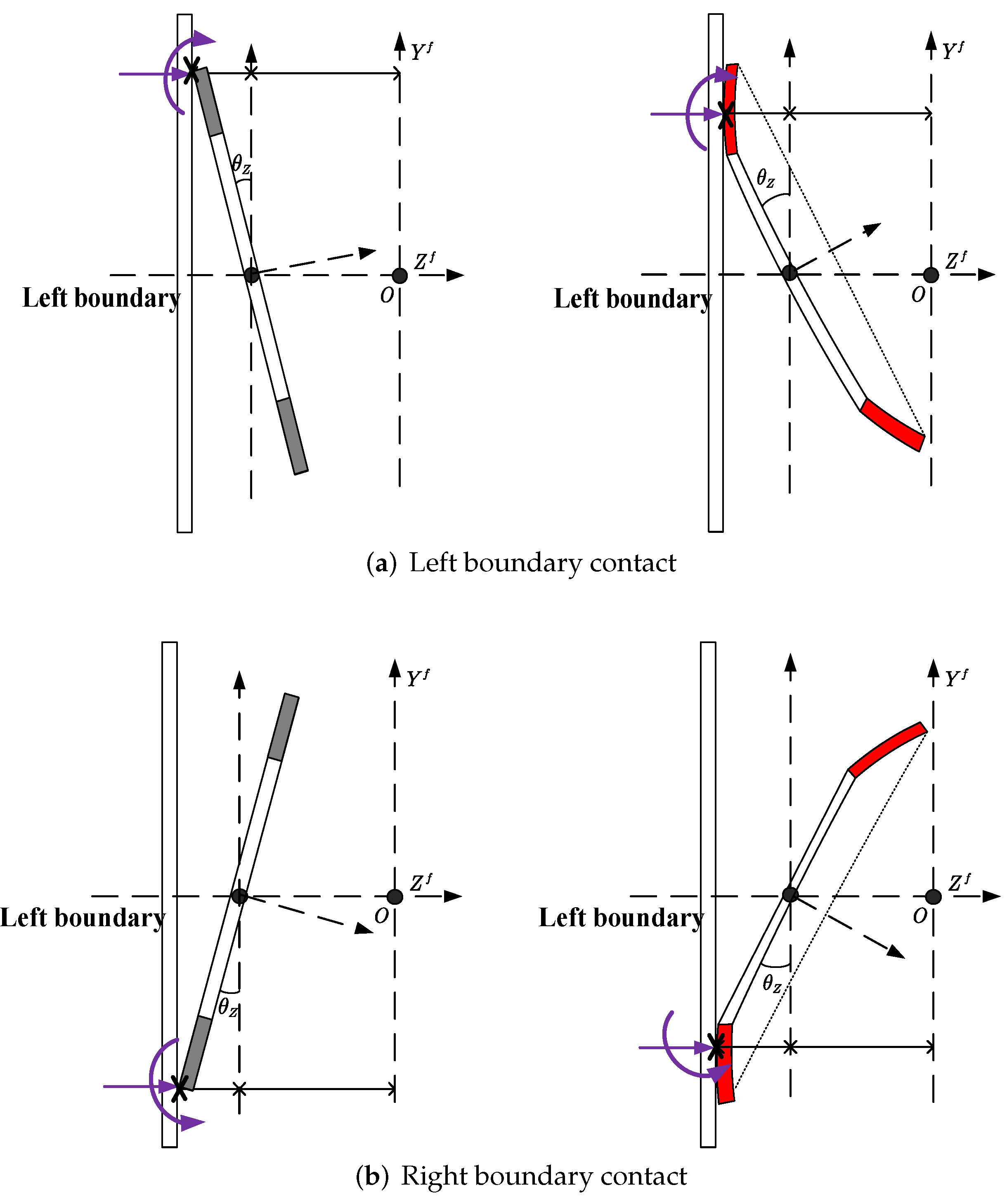
2.3. Boundary Impact Model of the Flat Disc

The boundary impact force occurs when the disc hits the boundary. Figure 7 shows the impact situations of deformed discs. On the right boundary, as shown in Figure 7b, the contact point of the deformed disc is always at the outer edge. However, the contact points on the left boundary are not certain. To explain this, the side views of the left boundary contact of both flat and deformed discs are drawn in Figure 8:
It can be easily inferred that the contact point of the flat disc always lies at the outer edge. However, the contact point of the deformed disc on the left boundary depends on the position and the tilting angle. In other words, any point across the axial coordinate Z b is the contact point. Assuming that the disc and boundary remain rigid in the process of impact, that the contact type of two curved surfaces is point contact, and that the contact pressure is perpendicular to the common tangent of the two surfaces, the boundary impact force of the disc can be written as [27]:
F N = 0 Z b Z i f Z b k δ n e l s e
where δ = Z i f Z b represents the amount of contact deformation. Z b is the boundary coordinate, n is the variable determined by the contact surface geometry, and k represents the generalized stiffness. For a contact between a sphere and a plane surface, n is taken as 1.5, and k can be calculated as [26]:
k = 4 3 π ( σ 1 + σ 2 ) R 1 σ j = 1 v 2 π E j j = 1 , 2 R 1 = w i 2 + r i 2
where R 1 is the contact radius and σ j is the contact stress, which is determined by Young’s modulus E j and Poisson’s ratio v of the contact bodies. Once the impact force is obtained, the impact moment can be written as:
M N = sgn ( θ i ) F N R 1 cos ( θ Z + θ P ) l m
where l m is the arm of the impact force and θ i is the local coordinate of the impact point.

2.4. Spline Force Characteristics

The boundary Condition of the inner spline interface needs to be derived for numerical analysis. Compared to the free and clamped interface, the spline boundary generates a friction force, which is opposite to the axial movement of the disc. Taking the displacement of the center point as the reference, the total spline force for the axial movement is [30]:
f s = sgn ( Z f ˙ ) μ m g
In this case, the coefficient of the spline friction is assumed to be 0.1 [31]. Similarly, the sign of the friction moment is related to the sign of the tilting velocity, which can be obtained by multiplying Equation (19) by the inner radius, so the spline friction moment is:
M f = sgn ( θ Z ˙ ) μ m g a

3. Numerical Analysis

The paper aims to provide intuition into the tilting; analytical calculations are postponed to future work, so only the Matlab/Simulink simulation is carried on with a 5 e 6 s -time-step ode8 solver.The simulated responses are the tilting and axial movement of the spinning discs subjected to an impulse force at their outer edges and the influence of the deformation angle, impulse force, and boundary distance on rigid-body tilting under different rotation speeds is discussed. The disc parameters are ρ = 7800 kg / m 3 , inner radius a = 0.010 m, outer radius b = 0.015 m, thickness h = 0.001 m, Young’s modulus E = 206 GPa and Poisson’s ratio v = 0.3 , referring to the scaled down disc used in the wet clutch [29]. The tested coefficients are the 1st-order deformation angle, angular velocity, impulse force and boundary distance as listed in Table 1. The rotation speeds are 40 rad/s (≈400 rpm), 120 rad/s (≈1200 rpm) and 200 rad/s (≈2000 rpm) to simulate low speed, medium speed and high speed, respectively. Group 1 is the reference group. The total simulation time was set to 2 s and the impulse force was applied at 0.2 s.

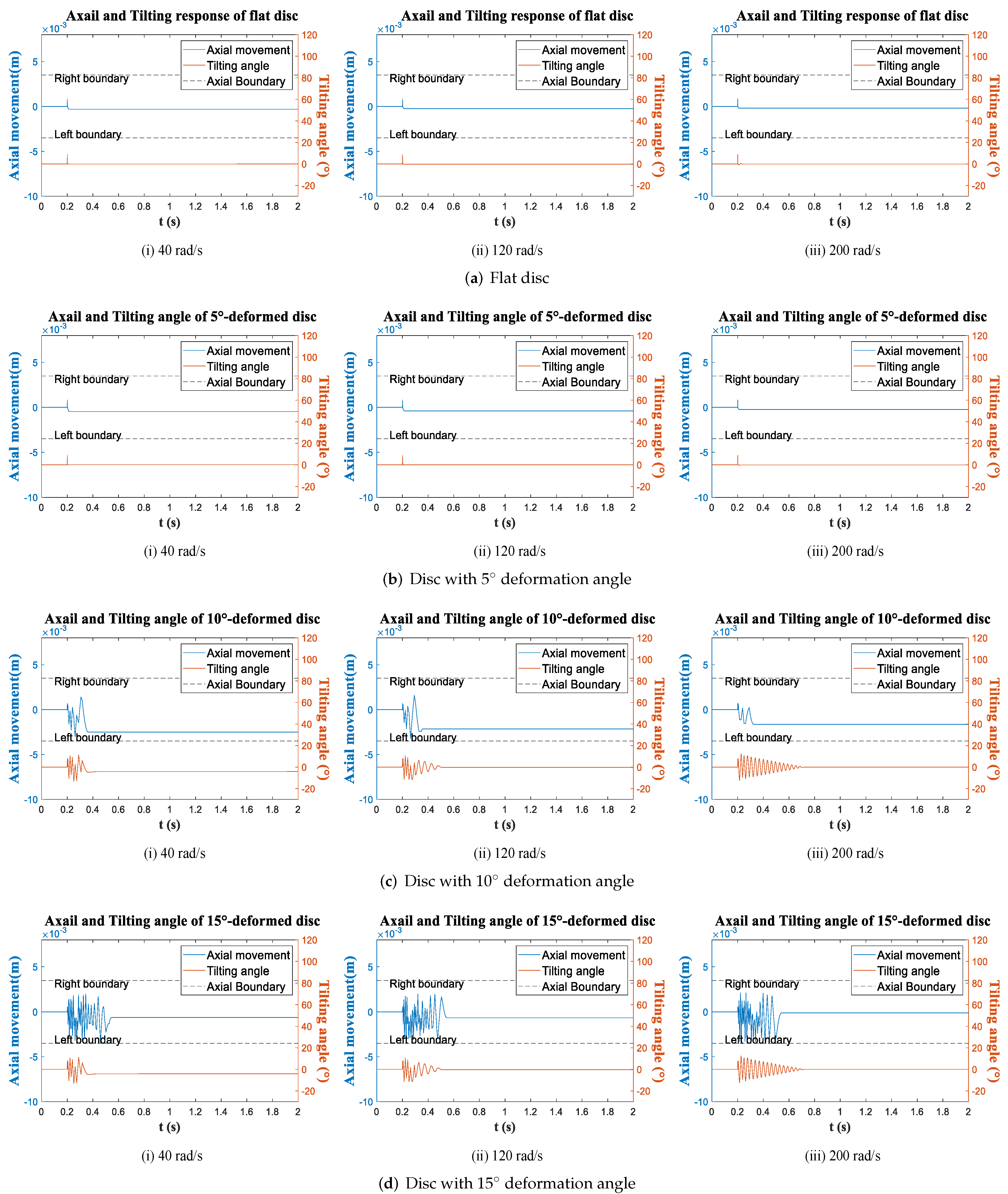
3.1. Time Response Analysis

The time histories of all working Conditions are obtained, and the tilting (orange line) and center point movement (blue line) of four discs at three Conditions are drawn in Figure 9, Figure 10 and Figure 11. In each figure, the deformation of the spinning discs are increased from (a) to (d), and sub-figures (i) to (iii) show the responses at different rotation speeds.
There are a few general observations from the 3 Conditions. First, the process of tilting and axial movement can be very short after the impulsion. Generally less than 1 s, take Figure 10d as an example, the motion of 15 -deformed disc under Condition 2 lasts the longest time, and the movements still ends within a second. Secondly, the tilting and axial movement of the disc are strongly correlated. In most cases they are hard to describe when two motions exist simultaneously such as Figure 10, which indicates that the discs constantly hit the boundary so the impact force keeps exerting on the discs. And once one movement stops, the other stops soon after. Additionally, the axial movement usually are very nonlinear, but when there is only tilting while the axial movement stops, as shown in Figure 10a(iii),b(iii), the tilting amplitude shows linear decay until to zero, which suggests if there is no boundary as well as the external force, free tilting motion is a decay motion, and the disc always aligns back to the vertical position.
Figure 9 and Figure 10 show the time responses with different impulse forces. The increase in impact force makes the motions of all discs more intense and longer lasting. For example, in Figure 9a, the tilting and axial translation of the flat disc stops at an instant, meaning that no impact occurs between the flat disc and boundary at Condition 1. When the impulse force increases from 5 N to 7 N in Figure 10a, the flat disc has a chance to impact the boundary so the motion becomes chaotic and last longer than Condition 1. In addition, comparing Figure 9 and Figure 11 show the influences of narrowing the boundary distance, somehow the effect is similar as to increase the impulsion, the motions of the four discs become more chaotic in Condition 3 (Figure 11) than in Condition 1 Figure 9. The reason is that the impact probability increases as the boundary distance decreases. Another influence is the boundary distance restrict the tilting angle. so in Figure 11, the amplitudes of the tilting angle of all discs are below 15 , smaller than those in Condition 1 and 2. Notably, the final axial position of the discs is difficult to predict. It is not always at the middle of two boundaries; it varies with the rotation speed, deformation of the discs, impulse force and boundary distance. For instance, 5 -deformed disc stops very close to the middle of the boundary in Figure 9b, while in Figure 10b it stops at 2 mm, 3 mm and −1 mm with different rotation speeds, and stops at 2 mm, −0.5 mm and −0.5 mm in Figure 11b. So the final steady displacement quite random which applies to all discs.
As for the influence of the deformation, one observation from Figure 9, Figure 10 and Figure 11 is that the discs with larger deformation angle has more intense and complex motions. Take 5 -deformed disc and 10 -deformed disc for comparison, in Condition 1 (Figure 9), the 5 -deformed disc return to the axial equilibrium position immediately after the impulsion, while the 10 -deformed disc tilts for 0.2 s at 40 rad/s and tilts even longer as angular velocity increases, and motions of 15 -deformed disc are more chaotic than 10 -deformed disc. To explain it, the deformation enlarges the axial displacement of the outer edge, so the deformed disc requires less tilting angle to reach the boundary, therefore deformation increase the possibility of the contact between the disc and the boundary. Another observation is the response of 5 -deformed disc are quite similar to the flat disc, both stops instantly in Condition 1 while tilts longer in Condition 2 and 3. So 5 deformation is significant enough.

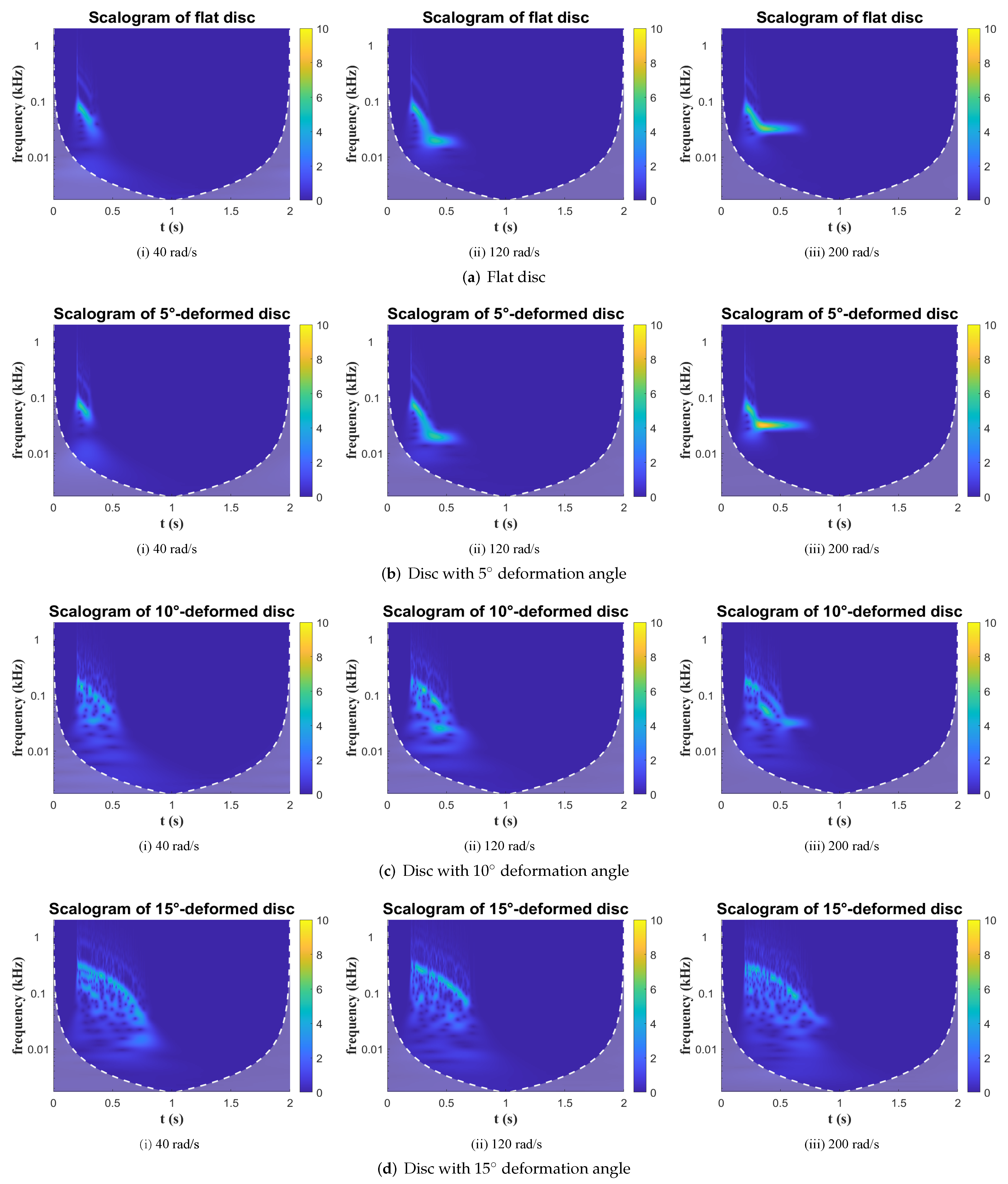
3.2. Frequency Analysis of Tilting Response

Since the tilting and the axial movement are correlated in a certain level, this section only analyzes the tilting responses by transferring the time domain signal into frequency domain. In this paper, the wavelet transform is selected as suitable for nonstationary signals [32]. Time-frequency scalogram plots of the tilting response are obtained and shown in Figure 12, Figure 13 and Figure 14 in accordance with Figure 9, Figure 10 and Figure 11. The X-axis represents time, the Y-axis represents the frequency on a logarithmic scale, and the color represents the power amplitude.
Some conclusions in the frequency domain are quite similar to those in the time domain. In all three Conditions, the frequency plots of the 5 -deformed disc and flat disc are quite similar, and both responses are almost invisible in Condition 1 (Figure 12) while becoming more intense with a larger impulse force or shorter boundary distance. Also, increasing the impulse force and reducing the boundary distance both enhance the power density of the tilting response. The power amplitude of the four discs in Figure 12 is less than those in the other two Conditions. Besides, impulse action could boost the magnitude level of the tilting frequency. In Figure 13, the initial tilting frequencies of four discs are up to 500 Hz, while the maximum frequencies in Condition 1 are about 100 Hz.
Additionally, the rotation speed can increase the power intensity of the tilting. Basically, all the response amplitudes at 200 rad/s are higher than those at 40 rad/s. Examples can be seen in Figure 13, the response of the 5 -deformed disc at 200 rad/s is much brighter and last longer than it is at 40 and 120 rad/s, as well as the 10 -deformed disc. Another phenomenon is that after the impulsion, the frequencies in all figures start to decline until fade away, which means the tilting is a decay process as concluded in time-domain analysis.
In the scalograms, less-deformed discs have quite clear shapes while larger deformed discs have rather distributed spectrum; for example, in Figure 13a and Figure 14a, the responses of the flat disc are clear curves, which means that the frequency bandwidth of the flat disc tilting is concentrated during the process. However, the nonlinearity of the tilting increases with progressive deformation (taking the 15 -deformed disc in Figure 13d and Figure 14d as examples), and the responses are distributed within a relatively large bandwidth, which means that the tilting is more chaotic and does not maintain at any specific frequency.

4. Conclusions

This paper presents a model governing the tilting and impact dynamics of a spinning splined disc with axial-fixed boundaries. The tilting and axial movement of different deformed discs are simulated via the state-space model in Simulink. Both time domain and frequency domain results are analyzed, and the results show the importance of disc deformation on the dynamic behaviors of spline-guided spinning discs. The analysis also considers cofactors such as boundary distance, initial impulse force and rotation speed. Several conclusions are drawn based on the results and analyses:
  • Regardless of the deformation, the disc tilting and axial motion are highly correlated. Both motions either show strong nonlinearity or stop immediately after the impulse, and when one motion stops the other stops soon. Also the final position of axial displacement is hard to predict, it varies as long as the condition changes.
  • The deformation of the disc increases the complexity of the tilting and axial motion of spinning discs. The dynamic responses of discs with larger deformation angles are more dramatic and longer than those of less-deformed discs, because the deformation of the disc increases the possibility of impact between the disc and boundary.
  • The effect of increasing the impulse force is similar to reducing the boundary distance; they both increase the intensity of the motions. The difference is that, narrowing the boundary distance could restrict the maximum tilting angle, and larger impulsion increase the tilting frequency. In addition, the rotation speed can also extend the time of tilting.
Further planned investigations will focus on the response of various types of excitation force, as well as developing multi-disc model to simulate the wet clutch system.

Author Contributions

Conceptualization, J.X., B.M. and M.C.; Methodology, L.Y. and J.X.; Simulation, J.X. and L.Y.; Software, J.X.; Validation, L.Z. and J.X.; Visualization, J.X. and L.Z.; Supervision, B.M. and M.C.; Funding acquisition, M.C.; Writing, J.X. and L.Z. All authors have read and agreed to the published version of the manuscript.

Funding

This research was funded by the National Natural Science Foundation of China (grant Nos. 51975047 and 51775045).

Institutional Review Board Statement

Not applicable.

Informed Consent Statement

Not applicable.

Data Availability Statement

Some or all data, models, or code generated or used during the study are available from the corresponding author by request.

Conflicts of Interest

The authors declare no conflict of interest.

References

  1. Khorasany, R.M.H.; Hutton, S.G. Large displacement analysis of elastically constrained rotating disks with rigid body degrees of freedom. Int. J. Mech. Sci. 2012, 54, 1–11. [Google Scholar] [CrossRef]
  2. Yu, L.; Ma, B.; Chen, M.; Li, H.; Zhang, H.; Liu, J. Thermodynamic Differences of Different Friction Pairs in a Multidisc Clutch Caused by Spline Friction: Numerical Simulation and Experimental Verification. Tribol. Trans. 2019, 62, 724–736. [Google Scholar] [CrossRef]
  3. Zhao, E.H.; Ma, B.; Li, H.Y. The Tribological Characteristics of Cu-Based Friction Pairs in a Wet Multidisk Clutch under Nonuniform Contact. J. Tribol. 2018, 140, 011401. [Google Scholar] [CrossRef]
  4. Cui, J.; Hou, P.; Zhang, B.; Zhao, X. Investigation of flow between deformed disks in hydro-viscous drive. Tribol. Int. 2018, 121, 287–301. [Google Scholar] [CrossRef]
  5. Hou, S.; Hu, J.; Peng, Z. Experimental investigation on unstable vibration characteristics of plates and drag torque in open multiplate wet clutch at high circumferential speed. J. Fluids Eng. Trans. ASME 2017, 139, 111103. [Google Scholar] [CrossRef]
  6. Zhang, Q.; Chen, M.; Xue, J.; Ma, B.; Li, H. The influence of friction component buckling on the vibration characteristic of the wet clutch. J. Phys. Conf. Ser. 2020, 1449, 012112. [Google Scholar] [CrossRef]
  7. Xue, J.; Ma, B.; Chen, M.; Zhang, Q.; Zheng, L. Experimental Investigation and Fault Diagnosis for Buckled Wet Clutch Based on Multi-Speed Hilbert Spectrum Entropy. Entropy 2021, 23, 1704. [Google Scholar] [CrossRef] [PubMed]
  8. Jeong, T.G.; Bogy, D.B. Measurements of Slider-Disk Contacts During Dynamic Load-Unload. IEEE Trans. Magn. 1991, 27, 5073–5075. [Google Scholar] [CrossRef]
  9. Chen, J.S.; Bogy, D.B. Effects of Load Parameters on the Natural Frequencies and Stability of a Flexible Spinning Disk with a Stationary Load System. J. Appl. Mech. 1992, 59, S230–S235. [Google Scholar] [CrossRef]
  10. Chen, J.S.; Bogy, D.B. Natural Frequencies and Stability of a Flexible Spinning Disk-Stationary Load System with Rigid-Body Tilting. J. Appl. Mech. 1993, 60, 470. [Google Scholar] [CrossRef]
  11. Pei, Y.C.; Tan, Q.C.; Zheng, F.S.; Zhang, Y.Q. Dynamic stability of rotating flexible disk perturbed by the reciprocating angular movement of suspensionslider system. J. Sound Vib. 2010, 329, 5520–5531. [Google Scholar] [CrossRef]
  12. Pei, Y.C.; Tan, Q.C.; Yang, X.; Chatwin, C. Vibrational response of a moving suspension-slider loading system exciting a rotating flexible disk. J. Sound Vib. 2012, 331, 3762–3773. [Google Scholar] [CrossRef]
  13. Li, C.; Wang, C.; Xia, W.; Zhang, C. Vortex-induced vibrations of an elastically mounted disk: The characteristics of wake and trajectory. Eur. J. Mech. B/Fluids 2021, 86, 113–122. [Google Scholar] [CrossRef]
  14. Fidlin, A.; Drozdetskaya, O.; Waltersberger, B. On the minimal model for the low frequency wobbling instability of friction discs. Eur. J. Mech. A Solids 2011, 30, 665–672. [Google Scholar] [CrossRef] [Green Version]
  15. Yang, L.; Mao, Z.; Chen, X.; Yan, R.; Xie, J.; Hu, H. Dynamic coupling vibration of rotating shaft–disc–blade system—Modeling, mechanism analysis and numerical study. Mech. Mach. Theory 2022, 167, 104542. [Google Scholar] [CrossRef]
  16. Miyasato, H.H.; Segala Simionatto, V.G.; Junior, M.D. On the interaction between rigid discs and rotating damped contact elements. Mech. Res. Commun. 2021, 111, 103644. [Google Scholar] [CrossRef]
  17. Cheng, L.; Li, Y.Y.; Yam, L.H. Vibration analysis of annular-like plates. J. Sound Vib. 2003, 262, 1153–1170. [Google Scholar] [CrossRef]
  18. Maretic, R. Transverse vibration and stability of an eccentric rotating circular plate. J. Sound Vib. 2005, 280, 467–478. [Google Scholar] [CrossRef]
  19. Carpino, M. The effect of initial curvature in a flexible disk rotating near a flat plate. J. Tribol. 1991, 113, 355–360. [Google Scholar] [CrossRef]
  20. Khorasany, R.M.; Hutton, S.G. The effect of axisymmetric nonflatness on the oscillation frequencies of a rotating disk. J. Vib. Acoust. Trans. ASME 2010, 132, 051012. [Google Scholar] [CrossRef]
  21. Khorasany, R.M.; Hutton, S.G. On the effects of a general form of the initial runout on the oscillation frequencies and critical speeds of a spinning disk. J. Sound Vib. 2011, 330, 6435–6455. [Google Scholar] [CrossRef]
  22. Olver, A.V. Regimes of Contact in Spline Couplings. J. Tribol. 2002, 124, 351–357. [Google Scholar] [CrossRef]
  23. Mohammadpanah, A.; Hutton, S.G. Theoretical and Experimental Verification of Dynamic Behaviour of a Guided Spline Arbor Circular Saw. Shock Vib. 2017, 2017, 6213791. [Google Scholar] [CrossRef] [Green Version]
  24. Mohammadpanah, A.; Hutton, S.G. Dynamics Behavior of a Guided Spline Spinning Disk, Subjected to Conservative In-Plane Edge Loads, Analytical and Experimental Investigation. J. Vib. Acoust. 2017, 138, 041005. [Google Scholar] [CrossRef]
  25. Zhang, L.; Wei, C.; Hu, J.; Hu, Q. Influences of lubrication flow rates on critical speed of rub-impact at high circumferential velocities in No-Load multi-plate wet clutch. Tribol. Int. 2019, 140, 105847. [Google Scholar] [CrossRef]
  26. Safaeifar, H.; Farshidianfar, A. A new model of the contact force for the collision between two solid bodies. Multibody Syst. Dyn. 2020, 50, 233–257. [Google Scholar] [CrossRef]
  27. Zhang, J.; Li, W.; Zhao, L.; He, G. A continuous contact force model for impact analysis in multibody dynamics. Mech. Mach. Theory 2020, 153, 103946. [Google Scholar] [CrossRef]
  28. Hu, J.; Hou, S.; Wei, C. Drag torque modeling at high circumferential speed in open wet clutches considering plate wobble and mechanical contact. Tribol. Int. 2018, 124, 102–116. [Google Scholar] [CrossRef]
  29. Yu, L.; Ma, B.; Chen, M.; Li, H.; Liu, J.; Li, M. Investigation on the failure mechanism and safety mechanical- thermal boundary of a multi-disc clutch. Eng. Fail. Anal. 2019, 103, 319–334. [Google Scholar] [CrossRef]
  30. Zheng, L.; Ma, B.; Chen, M.; Yu, L.; Wang, Q. Influence of the lubrication oil temperature on the disengaging dynamic characteristics of a cu-based wet multi-disc clutch. Appl. Sci. 2021, 11, 1299. [Google Scholar] [CrossRef]
  31. Cura, F.; Mura, A. Theoretical and numerical evaluation of tilting moment in crowned teeth splined couplings. Meccanica 2018, 53, 413–424. [Google Scholar] [CrossRef]
  32. Narin, A. Detection of Focal and Non-focal Epileptic Seizure Using Continuous Wavelet Transform-Based Scalogram Images and Pre-trained Deep Neural Networks. Irbm 2022, 43, 22–31. [Google Scholar] [CrossRef]
Figure 1. Common disc deformation types in a wet clutch.
Applsci 12 03637 g001
Figure 2. Rigid-body tilting of the spinning disc.
Applsci 12 03637 g002
Figure 3. Coordinates of the spline-guided disc.
Applsci 12 03637 g003
Figure 4. Force analysis of the spline-guided disc.
Applsci 12 03637 g004
Figure 5. Deformation of spinning discs.
Applsci 12 03637 g005
Figure 6. Deformation-induced inclined angle.
Applsci 12 03637 g006
Figure 7. Boundary impact of deformed discs.
Applsci 12 03637 g007
Figure 8. Left boundary impact of deformed discs.
Applsci 12 03637 g008
Figure 9. Time response: BC = 7 mm, initial force = 5 N.
Applsci 12 03637 g009
Figure 10. Time response: BC = 7 mm, initial force = 7 N.
Applsci 12 03637 g010
Figure 11. Time response: BC = 6 mm, initial force = 5 N.
Applsci 12 03637 g011
Figure 12. Scalogram: BC = 7 mm, initial force = 5 N.
Applsci 12 03637 g012
Figure 13. Scalogram: BC = 7 mm, initial force = 7 N.
Applsci 12 03637 g013
Figure 14. Scalogram: BC = 6 mm, initial force = 5 N.
Applsci 12 03637 g014
Table 1. Simulation parameters.
GroupImpulse ForceBoundary Distance
Condition 1 (reference group)5 N7 mm
Condition 27 N7 mm
Condition 35 N6 mm
Deformation angle [ ]0 (flat), 5, 10, 15
Angular velocity [rad/s]40, 120, 200
Publisher’s Note: MDPI stays neutral with regard to jurisdictional claims in published maps and institutional affiliations.

