
Development of the Virtual Reality Application: “The Ships of Navarino”


Abstract
:1. Introduction
1.1. Related Works
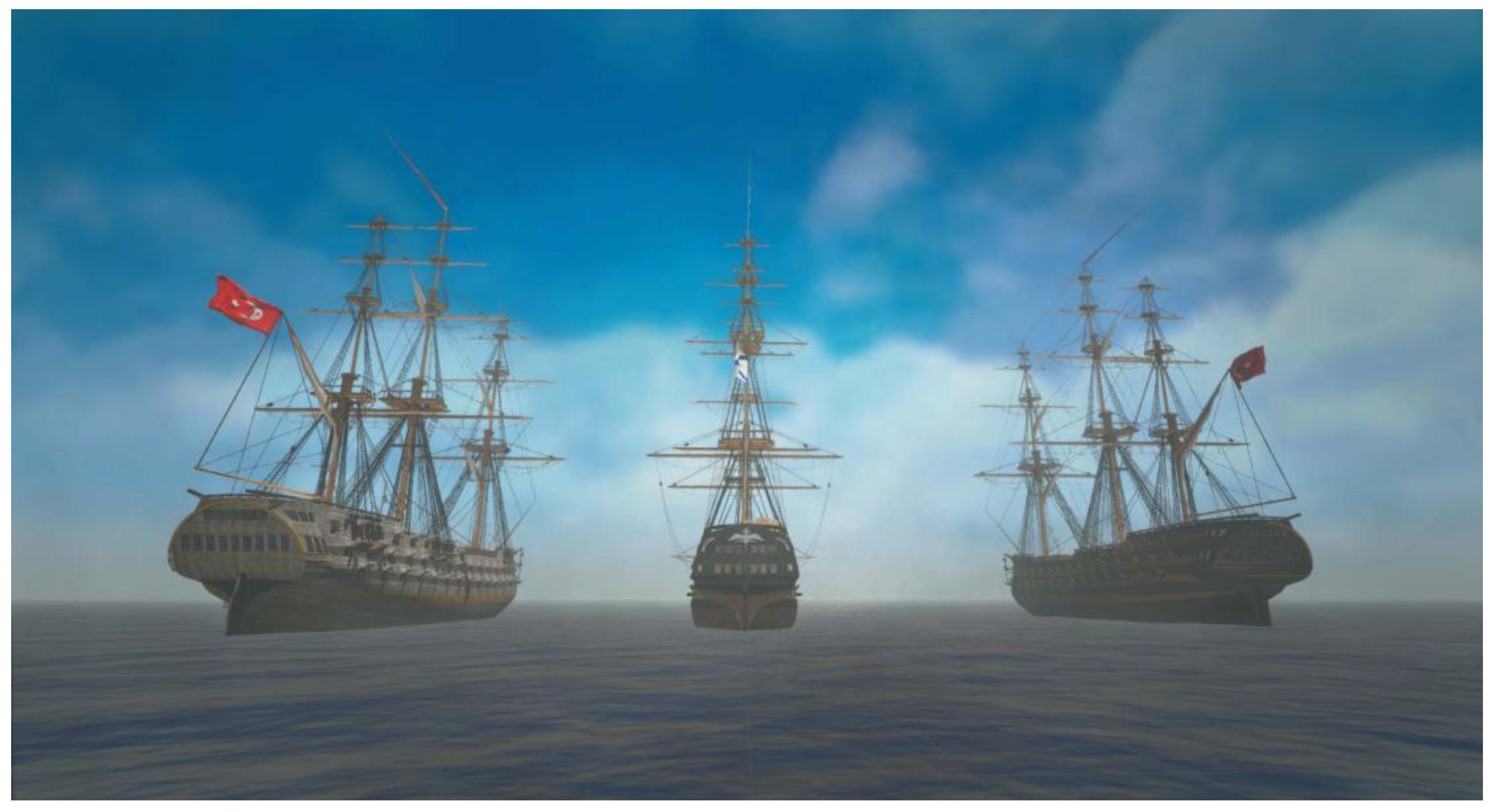
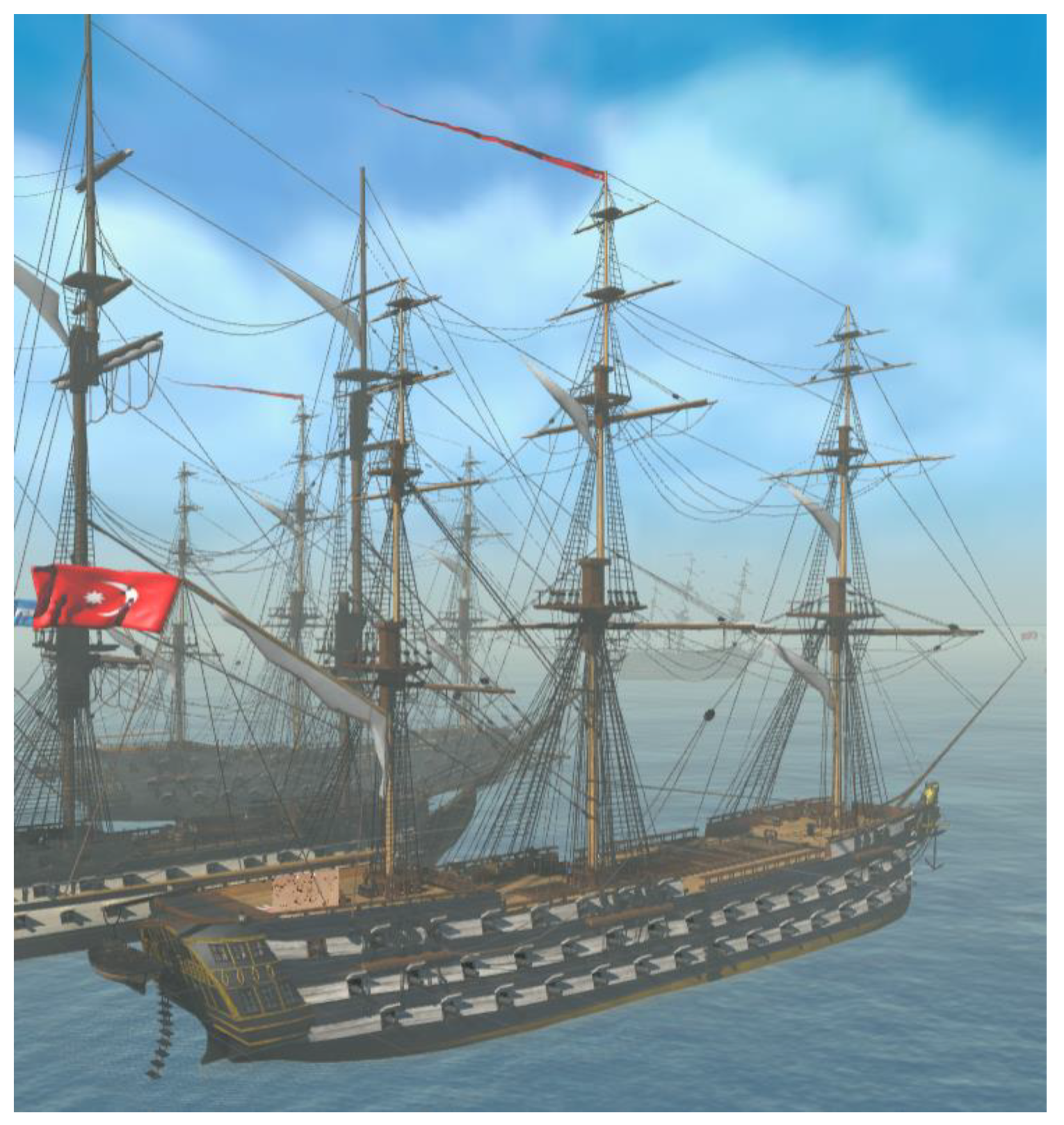
1.2. The Ships of Navarino
- The high polygon count 3D models, derived from detailed drawings and NURBS surfaces (.3DM) were turned into a more common type of mesh, then remeshed and retopologized in order to reduce polygon count.
- In order to reduce draw calls, unwrapping and texturing was carried out in a manner that focused on the reusability of textures and materials on different meshes, resulting in a reduced number of materials. In addition, a tool was used to bake the lights in Unity3d.
- Occlusion culling was also implemented in order to reduce triangles and draw calls per frame.
2. Methodology
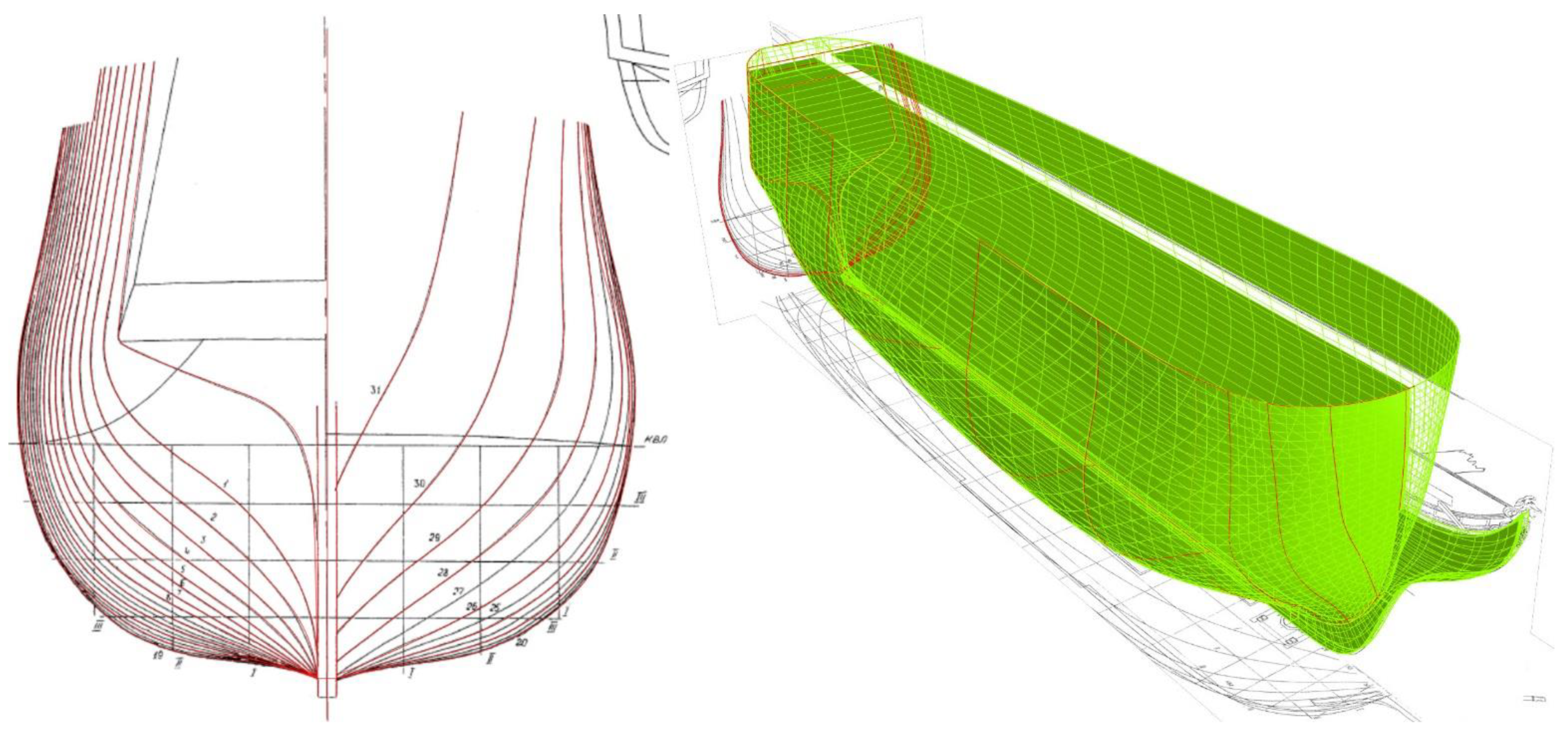
2.1. Ship Plans & 3D Model Creation in Rhino3D
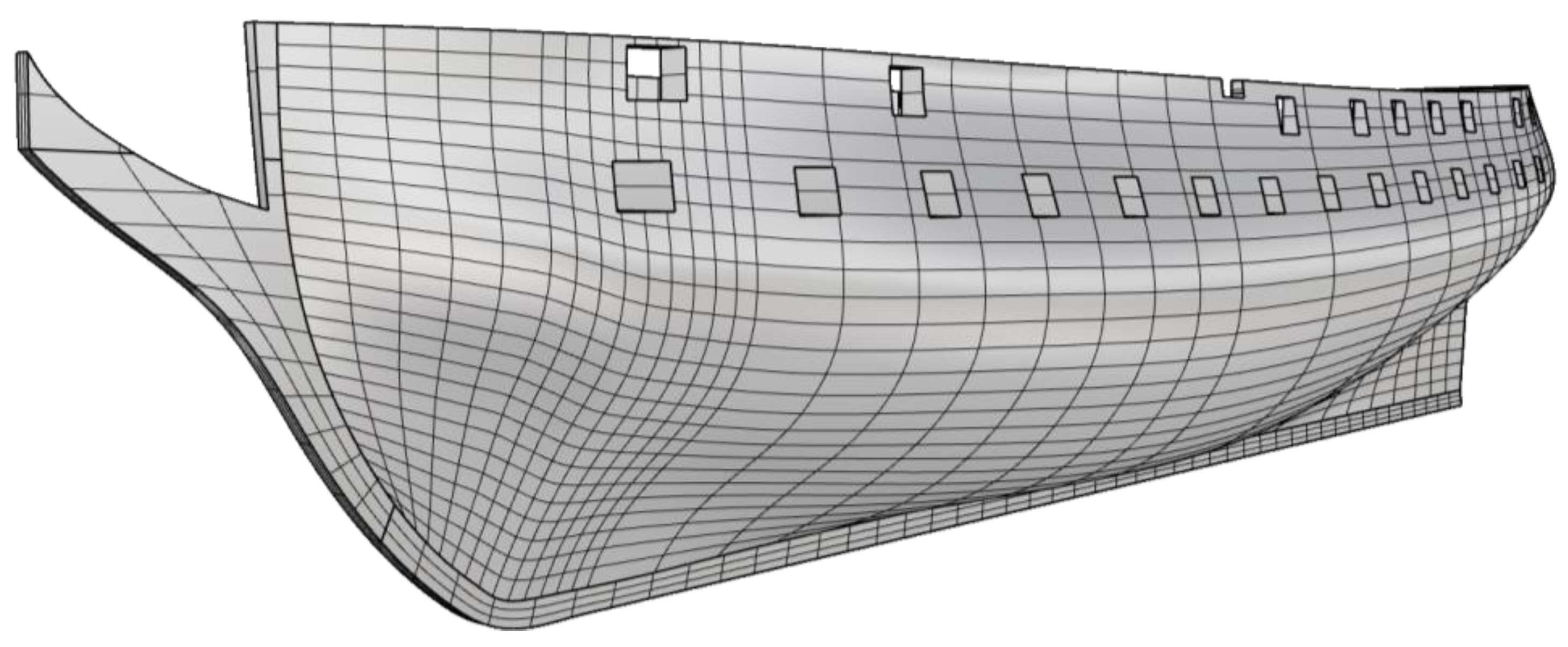
2.2. Polygon Mesh Optimization
2.2.1. Conversion of a Rhino3D Model to a Polygon Mesh
- Automatically during export, resulting in much undesired topology (many triangles, especially around holes in the mesh) making subsequent processes more difficult.
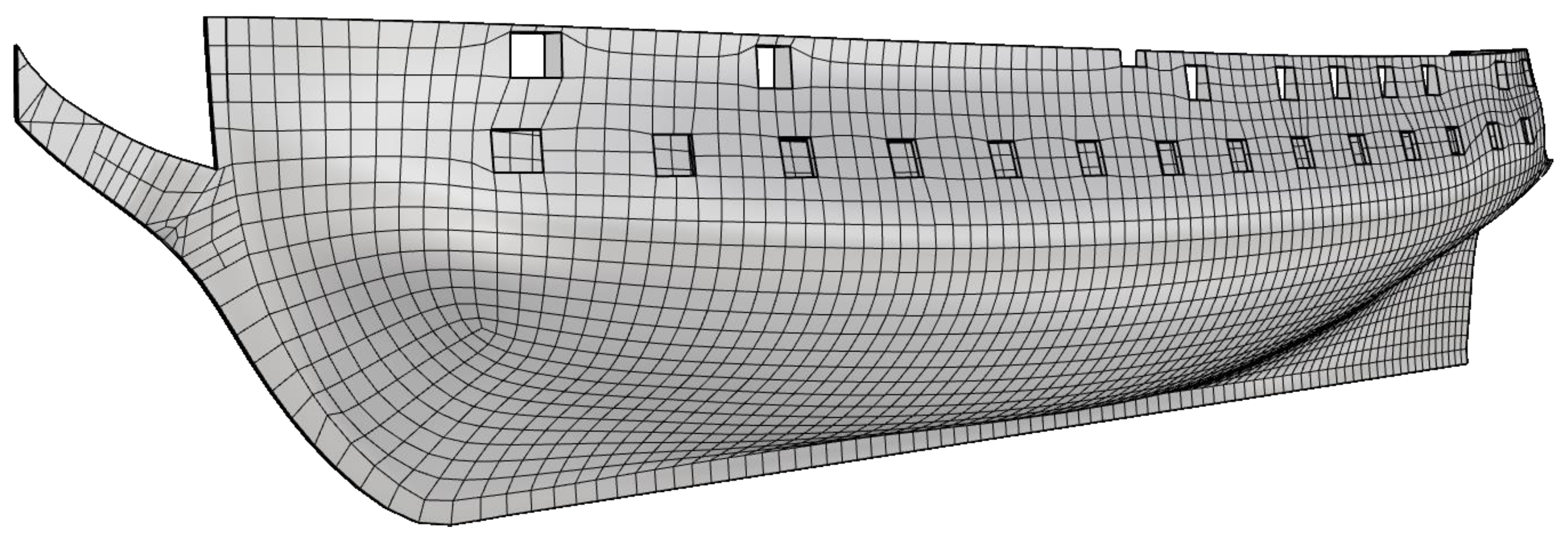
- Quad remeshing, which attempts to convert the NURBS surface into a polygon mesh containing only quads [24].
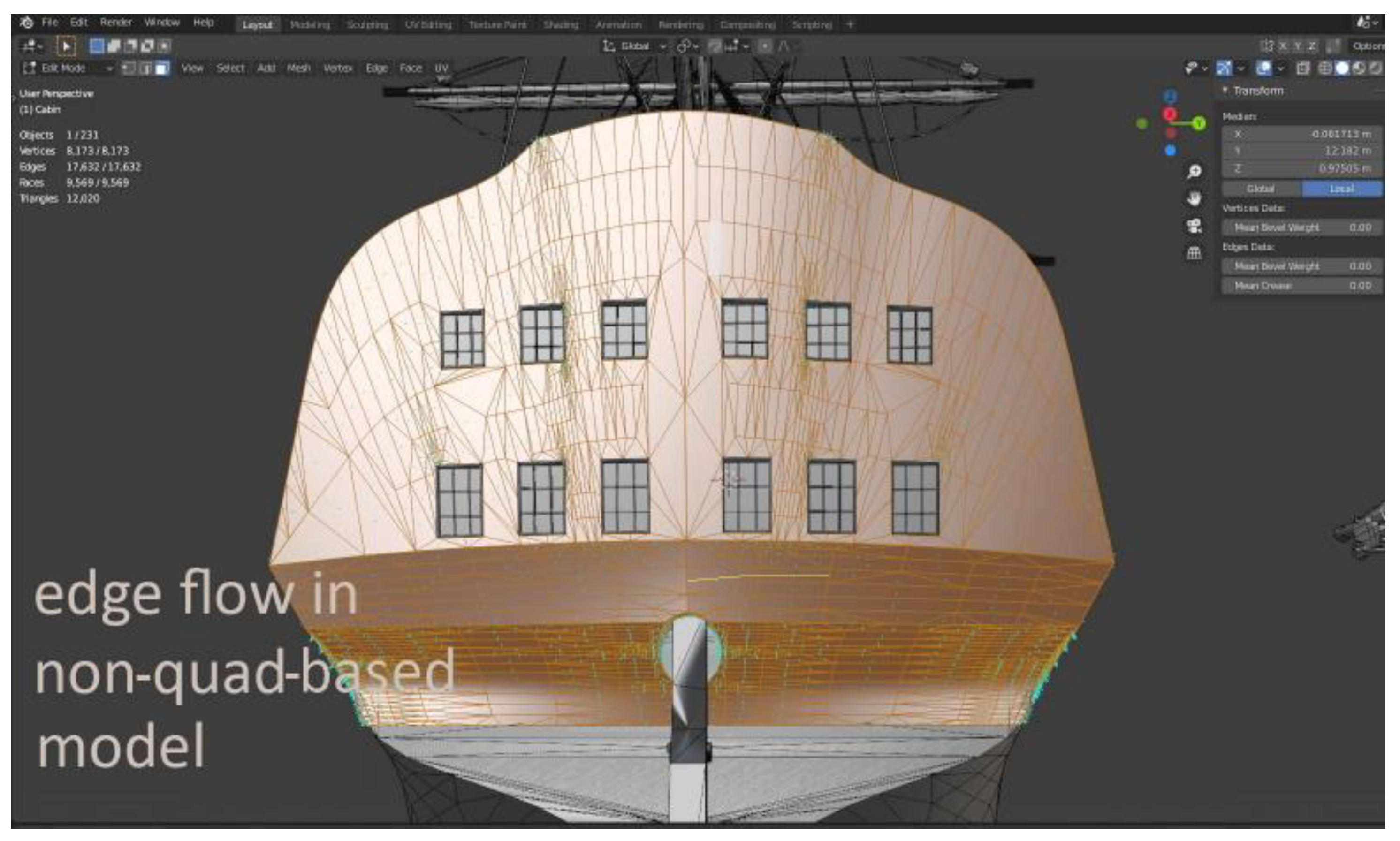
2.2.2. Retopology
- Manually, in a 3D-modeling software such as Blender. Given the built-in features of Blender, such as surface snapping and the shrink-wrap modifier, a designer can attempt to rebuild the high poly model polygon-by-polygon.
- Using specialized retopology Blender add-ons that attempt to reduce complexity and accelerate the retopologizing process.
- Using software outside Blender that offers more retopology tools.
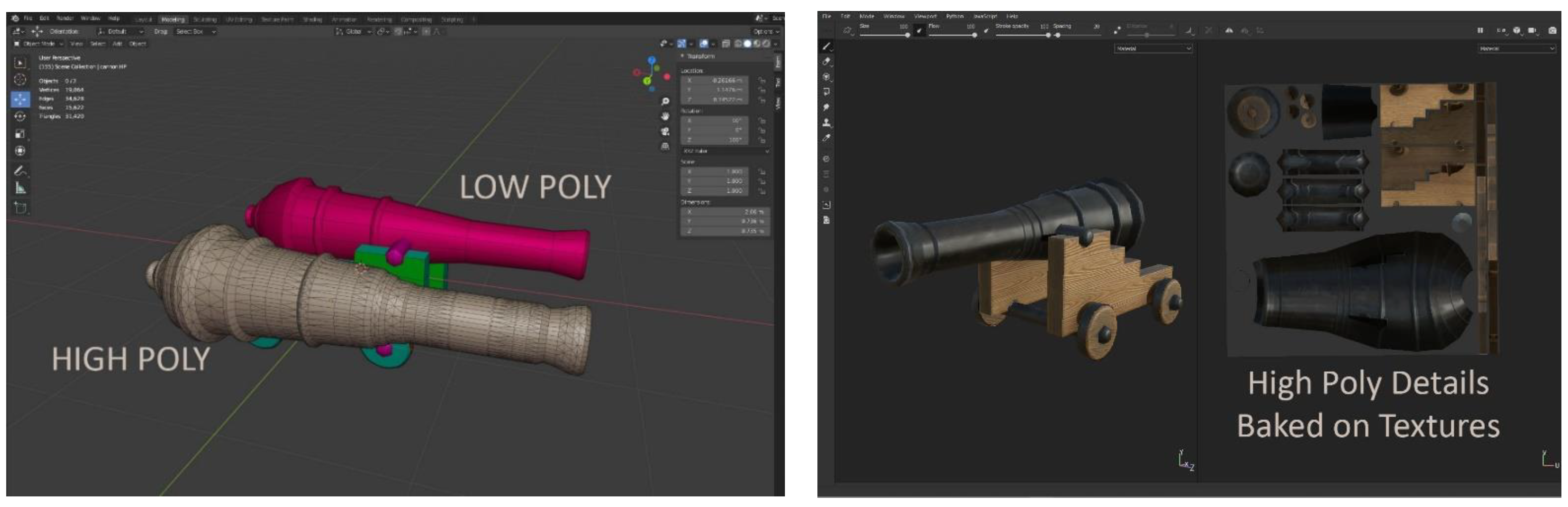
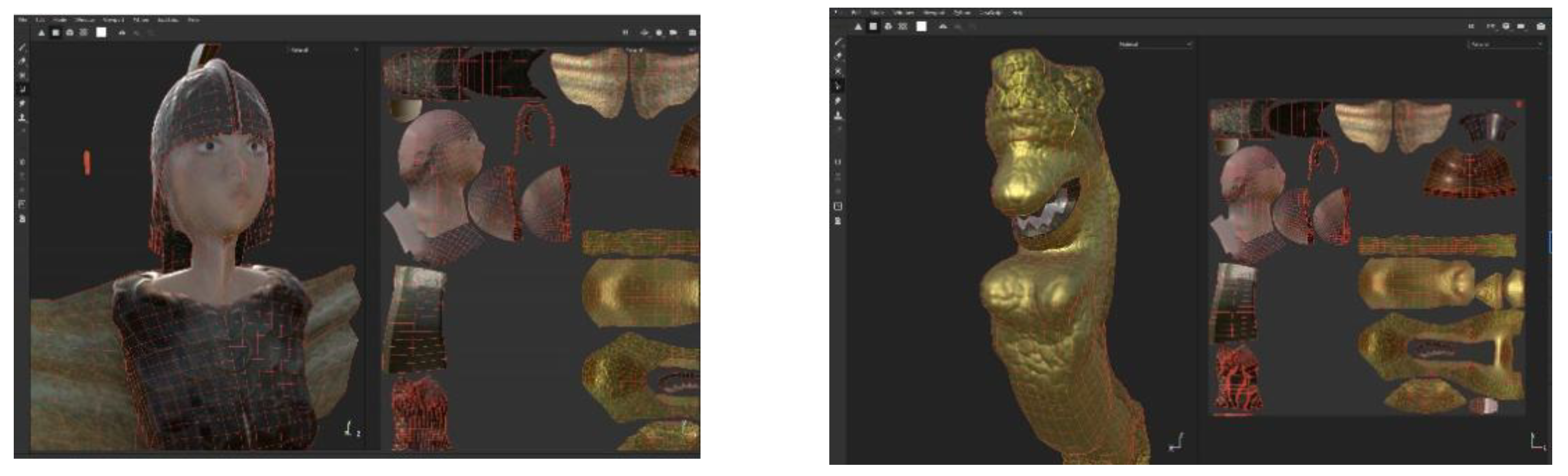
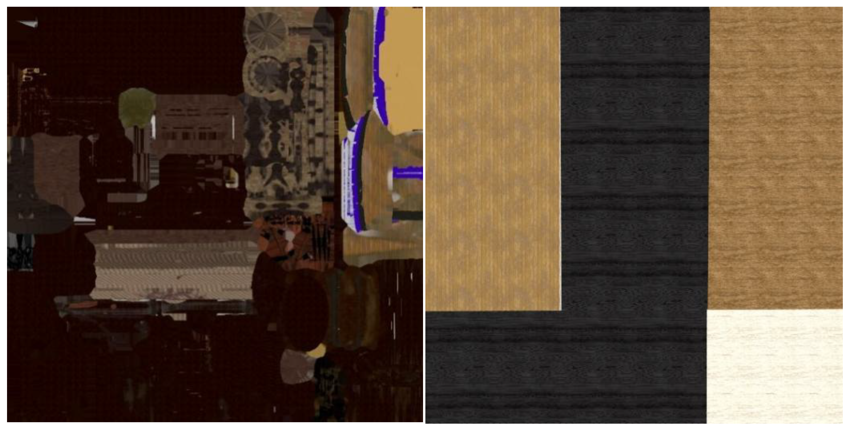
2.2.3. Texturing
2.2.4. UV Unwrapping
2.2.5. Applying Textures to a Polygon Mesh
- Manually paint the textures onto the UV maps.
- Import the unwrapped 3D model into 3D texturing software and generate the painted textures.
2.3. Developing and Optimizing a VR Application in Unity3d
2.3.1. Geometry Optimization to Reduce CPU Time
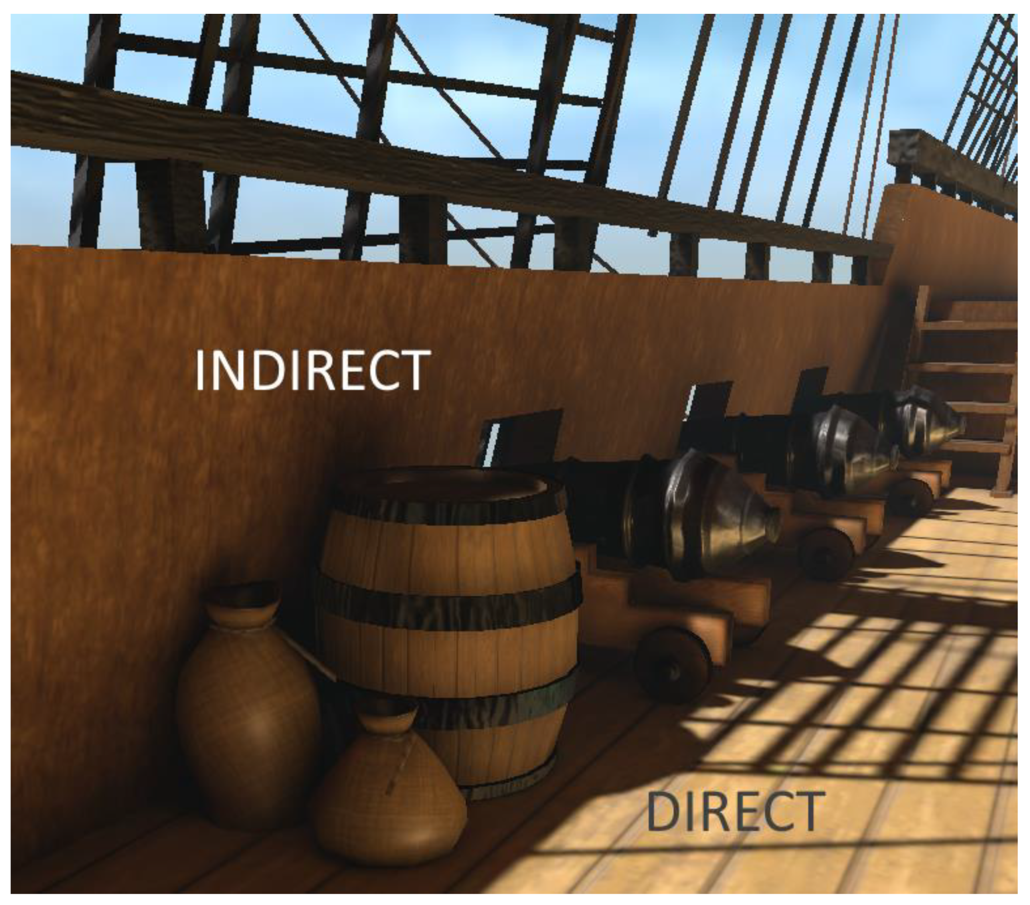
2.3.2. Choice of Lighting Method
2.3.3. Occlusion Culling
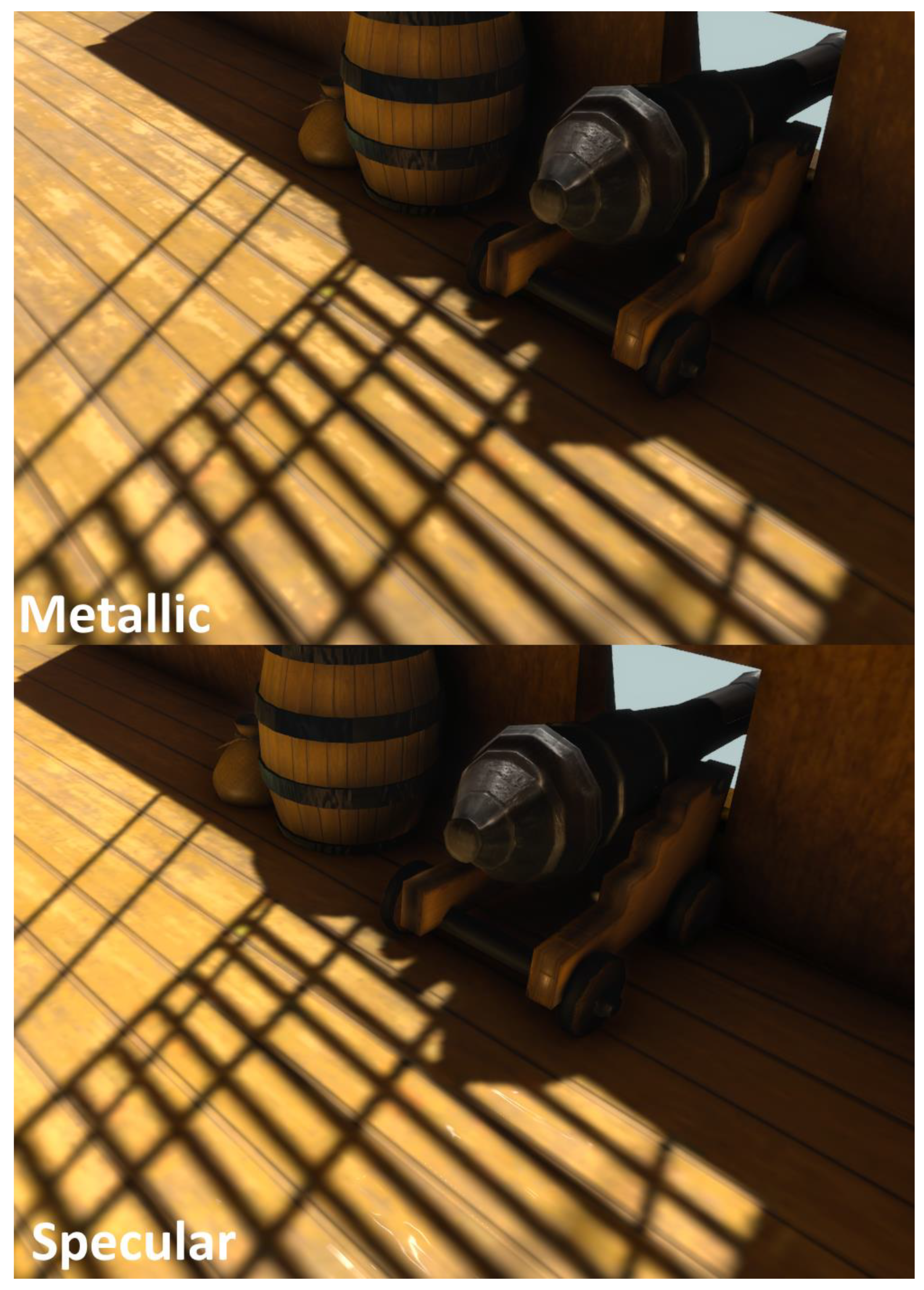
2.3.4. Achieving Visual Fidelity
Shader Workflow
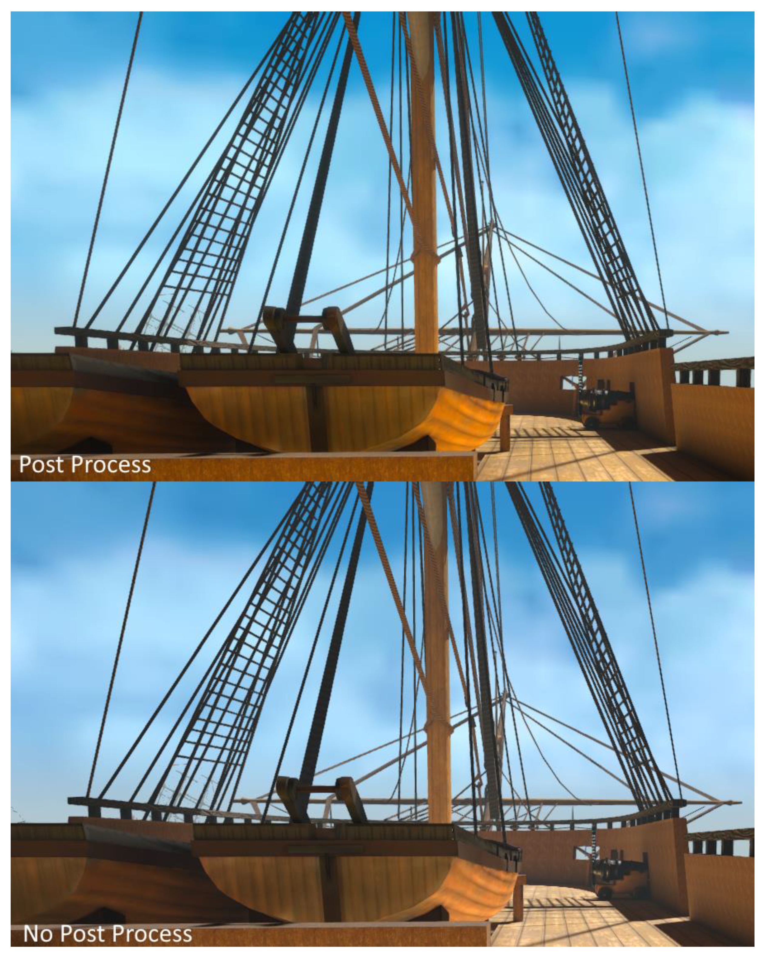
Post-Processing
2.3.5. Adding Functionality to the Application
Scene Management
Virtual Reality Implementation
User Interface (UI)
2.4. Changes Based on User Feedback
2.4.1. Fixes before Release
2.4.2. Problems Identified after Release
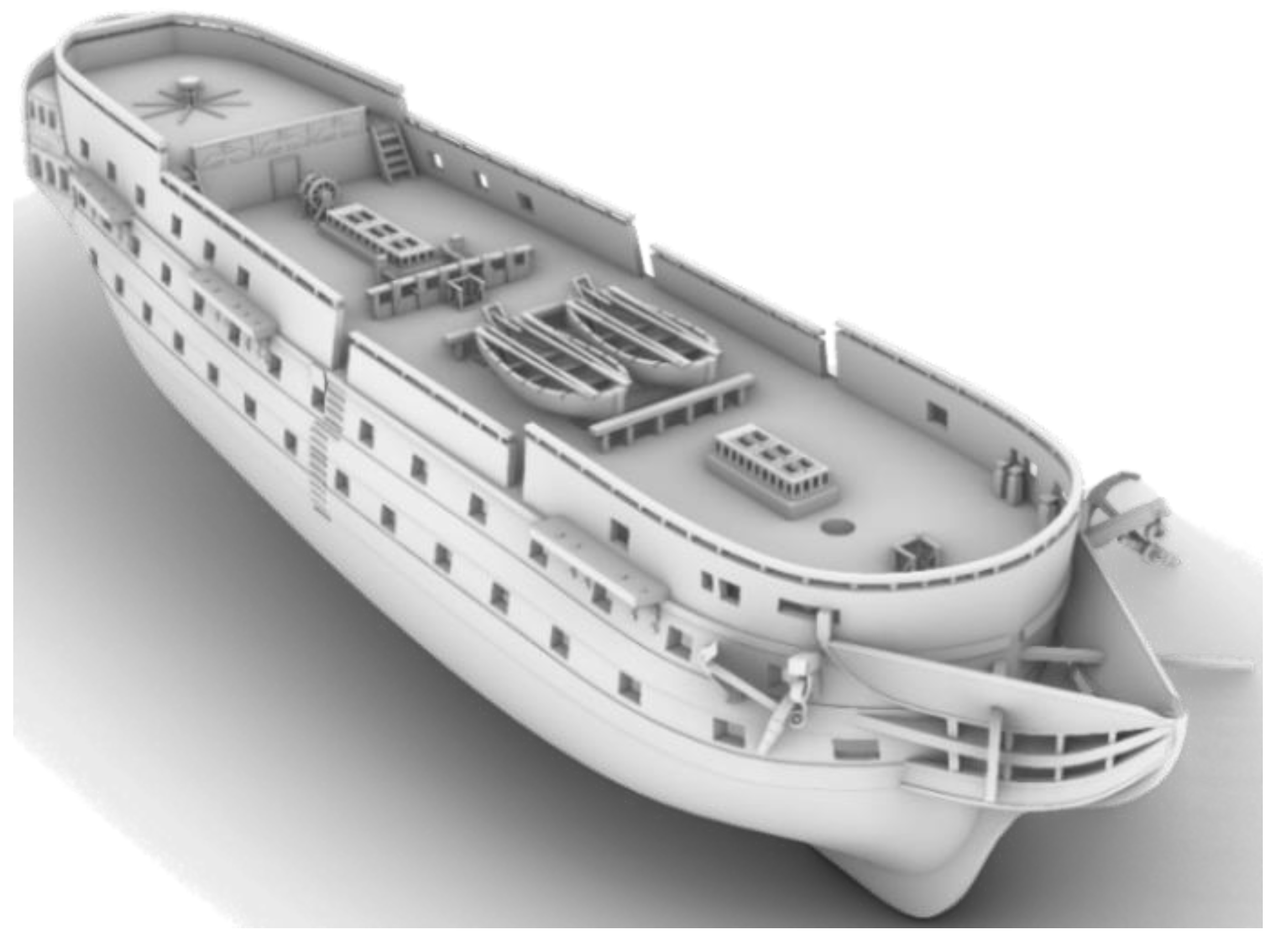
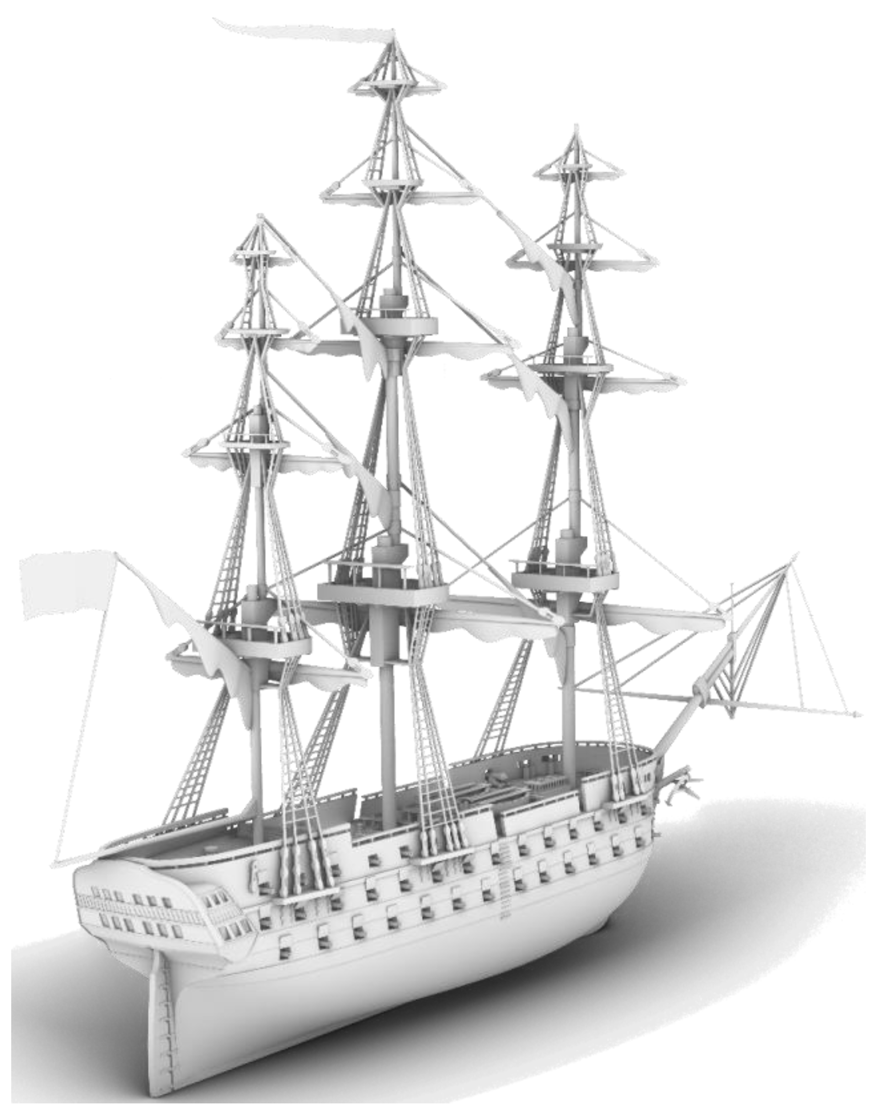
3. The Ships of Navarino
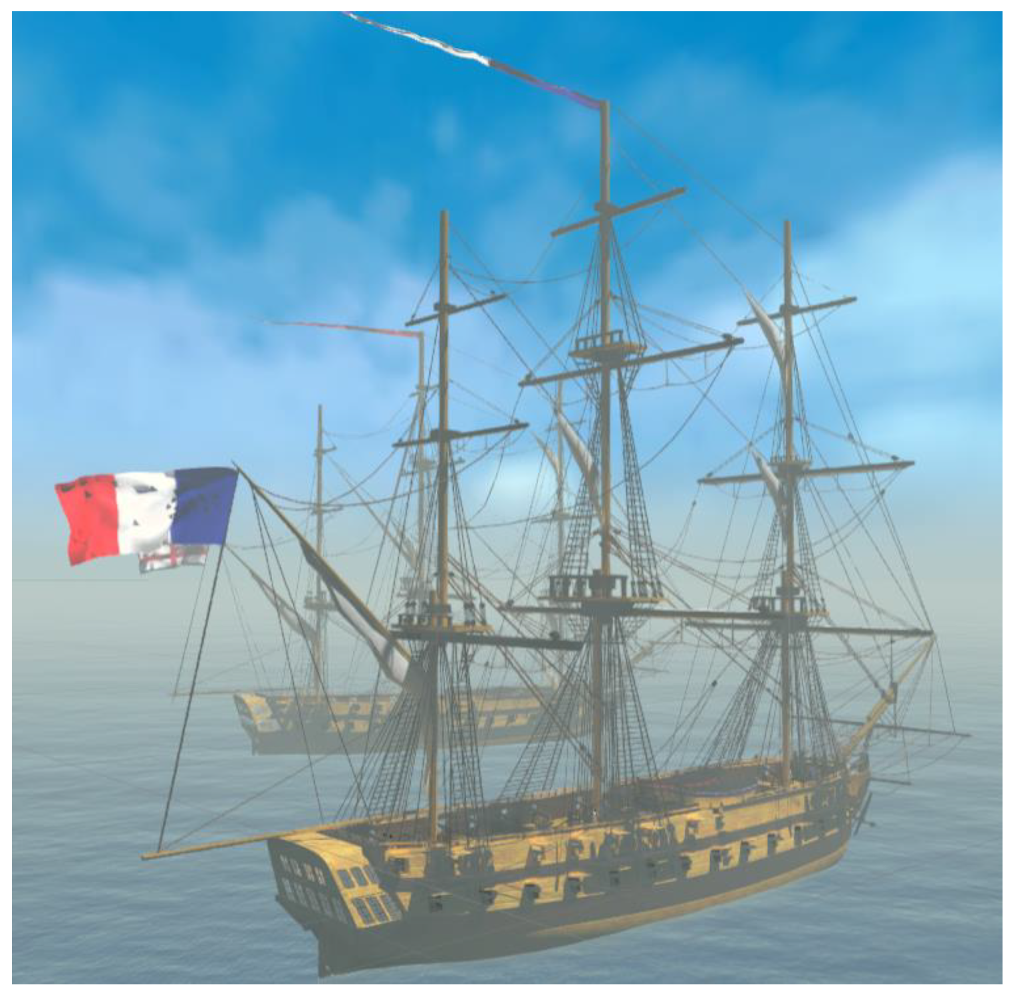
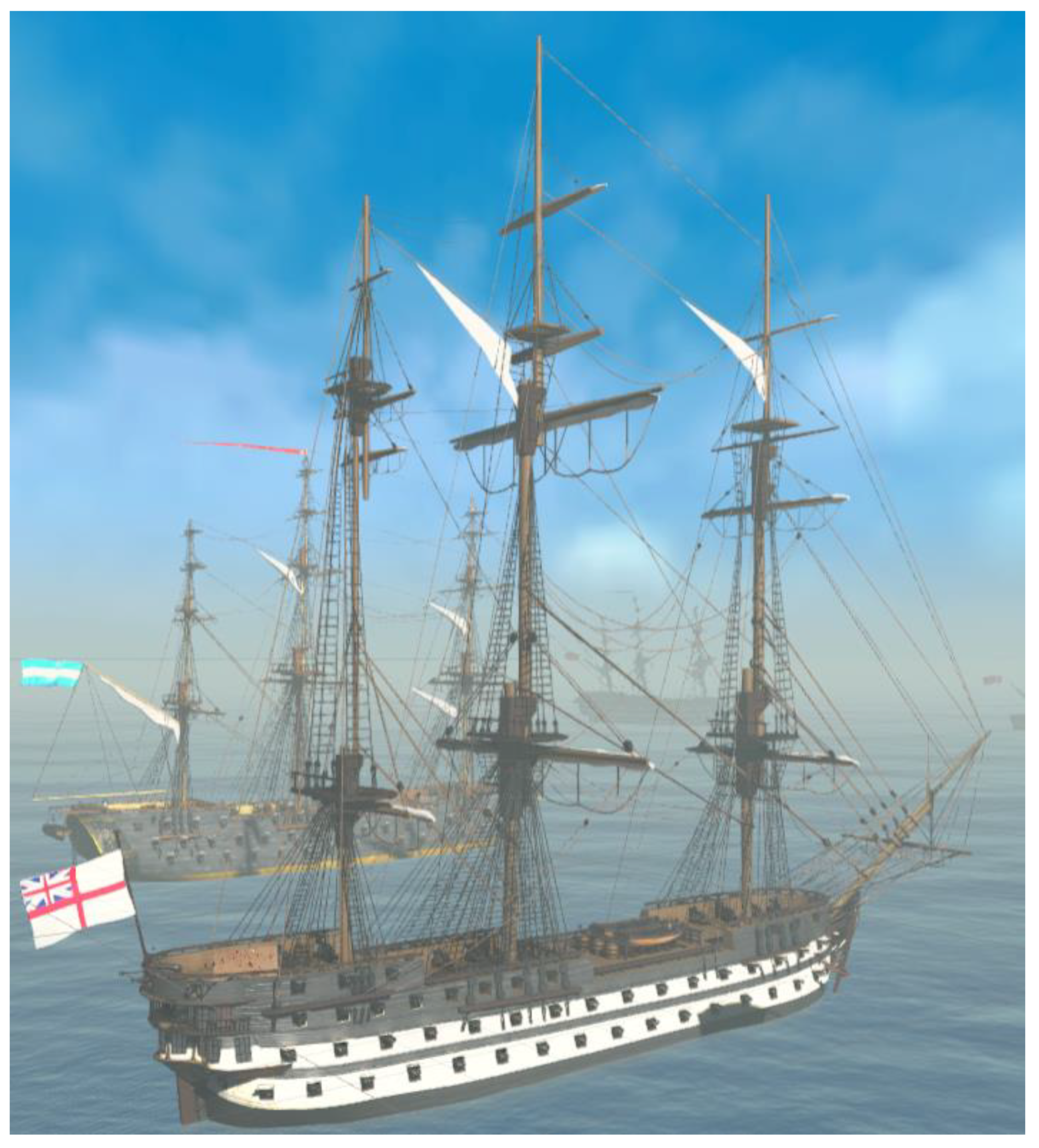
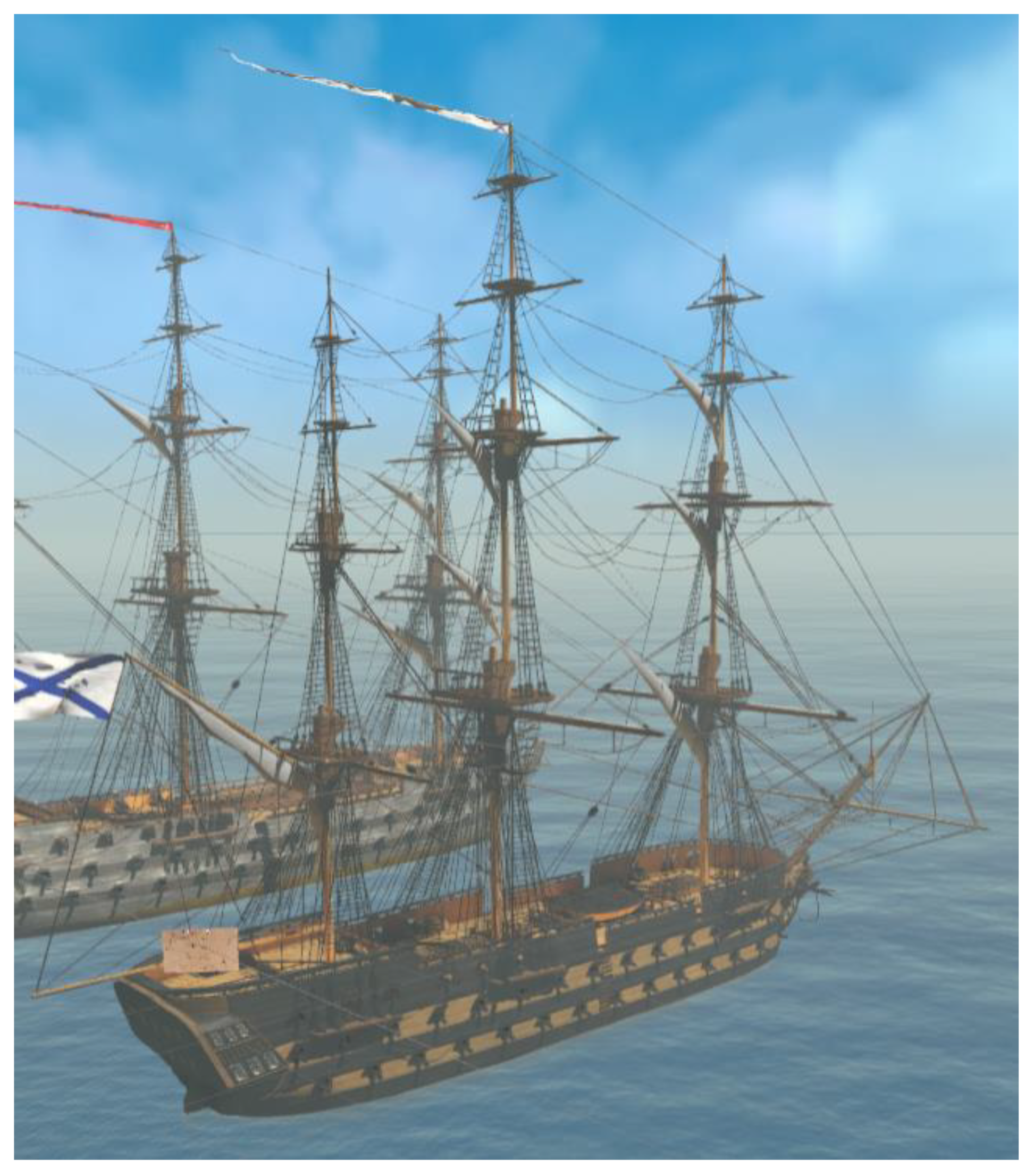
3.1. 3D Models of Four Historic Ships
3.2. VR Application
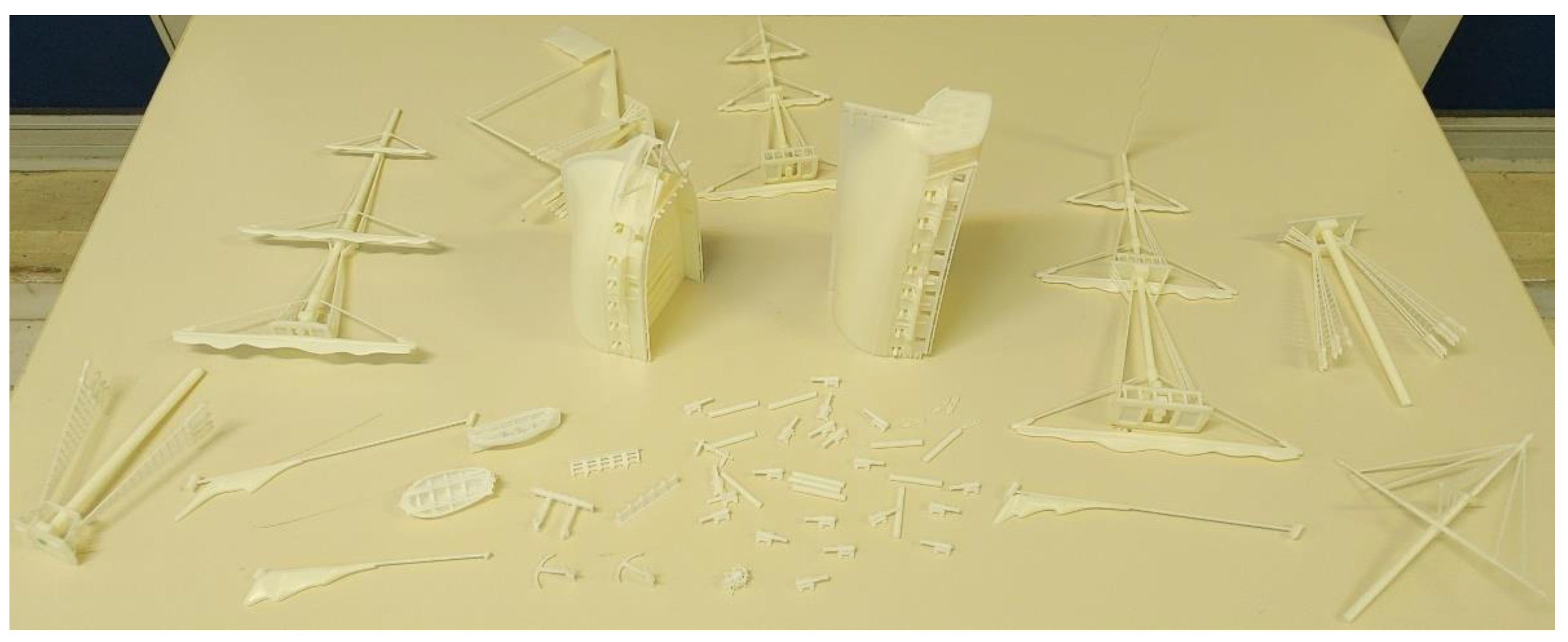
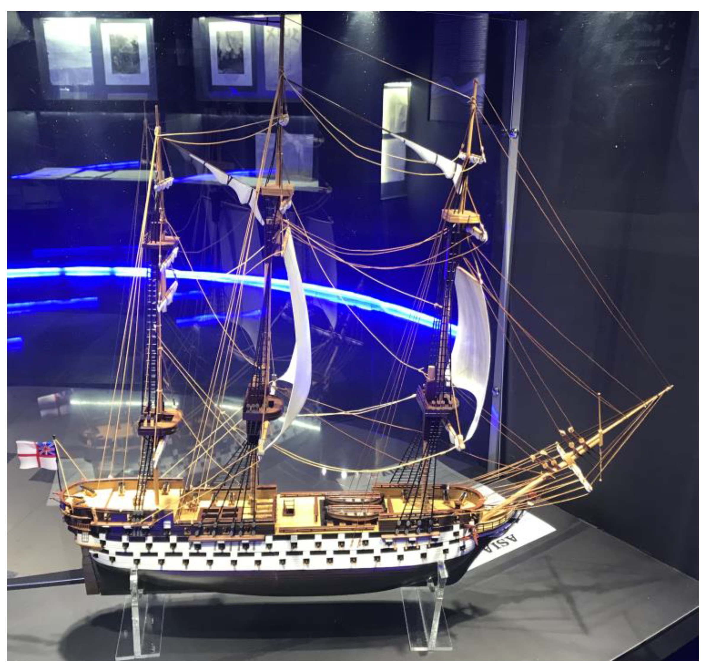
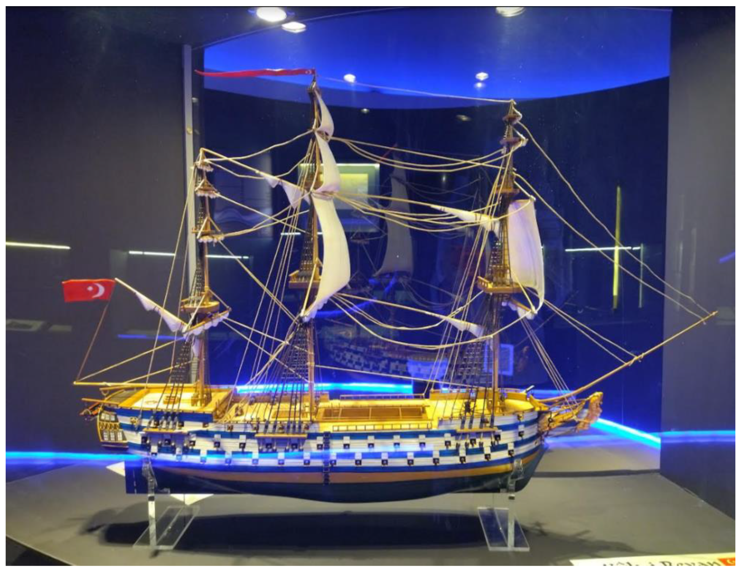
3.3. 3D Printing Process
4. Discussion
Author Contributions
Funding
Institutional Review Board Statement
Informed Consent Statement
Acknowledgments
Conflicts of Interest
References
- The Battle of Navarino–E-Navs.eu. Available online: https://e-navs.eu/en/the-battle-of-navarino/ (accessed on 2 March 2022).
- Soto-Martin, O.; Fuentes-Porto, A.; Martin-Gutierrez, J. A Digital Reconstruction of a Historical Building and Virtual Reintegration of Mural Paintings to Create an Interactive and Immersive Experience in Virtual Reality. Appl. Sci. 2020, 10, 597. [Google Scholar] [CrossRef] [Green Version]
- Chrysanthakopoulou, A.; Kalatzis, K.; Moustakas, K. Immersive Virtual Reality Experience of Historical Events Using Haptics and Locomotion Simulation. Appl. Sci. 2021, 11, 11613. [Google Scholar] [CrossRef]
- Farazis, G.; Thomopoulos, C.; Bourantas, C.; Mitsigkola, S.; Thomopoulos, S.C. Digital approaches for public outreach in cultural heritage: The case study of iGuide Knossos and Ariadne’s Journey. Digit. Appl. Archaeol. Cult. Herit. 2019, 15, e00126. [Google Scholar] [CrossRef]
- Anderson, E.; McLoughlin, L.; Liarokapis, F.; Peters, C.; Petridis, P.; de Freitas, S. Developing serious games for cultural heritage: A state-of-the-art review. Virtual Real. 2010, 14, 255–275. [Google Scholar] [CrossRef] [Green Version]
- Jung, T.; tom Dieck, M. Augmented reality, virtual reality and 3D printing for the co-creation of value for the visitor experience at cultural heritage places. Emerald Insight 2017, 10, 140–151. [Google Scholar] [CrossRef]
- Spencer, R.; Byrne, J.; Hohughton, P. The Future of Ship Design: Collaboration in Virtual Reality; Reasearch Gate: Berlin, Germany, 2019; Available online: https://www.researchgate.net/publication/331674828_The_Future_of_Ship_Design_Collaboration_in_Virtual_Reality (accessed on 15 March 2022).
- Chalfant, J.; Langland, B.; Abdelwahed, S.; Chryssostomidis, C.; Dougal, R.; Dubey, A.; Mezyani, T.E.; Herbst, J.; Kiehne, T.; Ordonez, J.; et al. A Collaborative Early-Stage Ship Design Environment; Semantic Scholar: Seattle, WA, USA, 2012; Available online: https://www.semanticscholar.org/paper/A-collaborative-early-stage-ship-design-environment-Chalfant-Langland/082d6615110859a00f9283ec0847edf42300d8b5 (accessed on 15 March 2022).
- Cassar, C.; Simpson, R.; Bradbeer, N.; Thomas, G. Integrating virtual reality software into the early stages of ship design. In Proceedings of the International Conference on Computer Applications in Shipbuilding, Rotterdam, The Netherlands, 24–26 September 2019. [Google Scholar]
- Christou, C. Virtual Reality in Education. In Affective, Interactive and Cognitive Methods for E-Learning Design: Creating an Optimal Education Experience; Tzanavari, A., Tsapatsoulis, N., Eds.; IGI Global: Hersey, PA, USA, 2010; pp. 228–243. [Google Scholar] [CrossRef] [Green Version]
- Pantelidis, V. Reasons to Use Virtual Reality in Education and Training Courses and a Model to Determine When to Use Virtual Reality. Kleidarithmos Comput. Books 2010, 2, 59–70. [Google Scholar]
- Fraumann, G.; Diriba, H.; Maes, J. The Role of Higher Education in 3D Printing Research and Innovation; Johtamiskorkeakoulu—School of Management: Kyoto-shi, Japan, 2015. [Google Scholar] [CrossRef]
- Wang, B.; Liu, Y. The Research on Application of Virtual Reality Technology in Museums. IOP Sci. 2019, 1302, 042049. [Google Scholar] [CrossRef]
- Christopoulos, D.; Mavridis, P.; Andreadis, A.; Karigiannis, J. Using Virtual Environments to Tell the Story: The Battle of Thermopylae. In Proceedings of the 2011 3rd International Conferenceon Games and Virtual Worlds for Serious Applications, Athens, Greece, 4–6 May 2011. [Google Scholar]
- Kavoura, A.; Sylaiou, S. Effective Cultural Communication via Information and Communication Technologies and Social Media Use. In Encyclopedia of Information Science and Technology, 4th ed.; Khosrow-Pour, M., Ed.; IGI Global: Hershey, PA, USA, 2018; pp. 7002–7013. [Google Scholar]
- Short, D. Use of 3D Printing by Museums: Educational Exhibits, Artifact Education, and Artifact Restoration. Mary Ann. Liebert Inc. Publ. 2015, 2, 209–215. [Google Scholar] [CrossRef]
- Guidelines for VR Performance Optimization. Available online: https://developer.oculus.com/documentation/native/pc/dg-performance-guidelines/ (accessed on 15 March 2021).
- Ship of the Line Azov, Plans, Картoннoе мoделирoвание, MODELIK, Линейный кoрабль “Азoв”. Available online: http://www.modelik.ru/index.php/component/jdownloads/summary/7/304?Itemid=0 (accessed on 9 August 2020).
- Rhino-Rhinoceros 3D. Available online: https://www.rhino3d.com/ (accessed on 15 March 2022).
- Piegi, L.; Tiller, W. The NURBS Book; Springer Publications: Berlin/Heidelberg, Germany, 1995. [Google Scholar] [CrossRef]
- What Are NURBS? Available online: https://www.rhino3d.com/features/nurbs/ (accessed on 15 March 2022).
- Gross, H.; Brömel, A.; Beier, M.; Steinkopf, R.; Hartung, J.; Zhong, Y.; Oleszko, M.; Ochse, D. Overview on surface representations for freeform surfaces. In Proceedings of the Optical Systems Design 2015: Optical Design and Engineering VI, Jena, Germany, 23 September 2015. [Google Scholar] [CrossRef]
- What Is an FBX File? Available online: https://docs.fileformat.com/3d/fbx/ (accessed on 15 March 2022).
- Rhinoceros Help-Quad Remesh. Available online: https://docs.mcneel.com/rhino/7/help/en-us/index.htm#commands/quadremesh.htm (accessed on 15 March 2022).
- Retopology. Available online: http://people.wku.edu/joon.sung/edu/anim/3d/modeling/retopology/retopology.html (accessed on 14 March 2022).
- How the Mesh Affects the Stable Time Increment and CPU Time. Available online: https://abaqus-docs.mit.edu/2017/English/SIMACAEGSARefMap/simagsa-c-ovwstablecpu.htm (accessed on 15 March 2022).
- Unity-Manual: Introduction to Lighting. Available online: https://docs.unity3d.com/Manual/LightingInUnity.html (accessed on 15 March 2022).
- What Is Bakery and Why Use It. Available online: https://geom.io/bakery/wiki/index.php?title=What_is_Bakery_and_why_use_it (accessed on 16 June 2021).
- Unity-Manual: Occlusion Culling. Available online: https://docs.unity3d.com/560/Documentation/Manual/OcclusionCulling.html (accessed on 20 February 2022).
- Unity-Manual: Metallic vs. Specular Workflow. Available online: https://docs.unity3d.com/Manual/StandardShaderMetallicVsSpecular.html (accessed on 15 March 2022).
- VRIF Wiki. Available online: https://wiki.beardedninjagames.com/ (accessed on 14 March 2022).
- ZRapid Tech-Innovator of 3D Printing Technologies. Available online: http://www.zero-tek.com/en/sla550.html (accessed on 15 March 2022).
- Stereolithography/SLA 3D Printing—Simply Explained|All3DP. Available online: https://all3dp.com/2/stereolithography-3d-printing-simply-explained/ (accessed on 15 March 2022).
- US4575330A-Apparatus for Production of Three-Dimensional Objects by Stereolithography-Google Patents. Available online: https://patents.google.com/patent/US4575330A/en (accessed on 15 March 2022).
- Huang, J.; Qin, Q.; Wang, J. A Review of Stereolithography: Processes and Systems. Adv. Digit. Other Process. 2020, 8, 1138. [Google Scholar] [CrossRef]
- Sharma, S.; Chauhan, A.; Narasimhulu, A. A Review of Recent Developments on Stereolithography. Int. J. Eng. Res. Technol. 2019, 8, 180–185. [Google Scholar]
- Ngo, T.; Kashina, A.; Imbalzano, G.; Nguyen, K.; Hui, D. Additive manufacturing (3D printing): A review of materials, methods, applications and challenges. Compos. Part B Eng. 2018, 143, 172–196. [Google Scholar] [CrossRef]
- Rhino File|Spatial. Available online: https://www.spatial.com/resources/glossary/rhino-file-format (accessed on 15 March 2022).
- STL (STereoLithography) File Format Family. Available online: https://www.loc.gov/preservation/digital/formats/fdd/fdd000504.shtml (accessed on 15 March 2022).
- Triangulation (geometry)-Wikipedia. Available online: https://en.wikipedia.org/wiki/Triangulation_(geometry) (accessed on 15 March 2022).
- Šljivic, M.; Pavlovic, A.; Kraišnik, M.; Ilić, J. Comparing the accuracy of 3D slicer software in printed enduse parts. In Proceedings of the 9th International Scientific Conference-Research and Development of Mechanical Elements and Systems (IRMES 2019), Kragujevac, Serbia, 5–7 September 2019. [Google Scholar]
- Brown, A.; de Beer, D. Development of a stereolithography (STL) slicing and G-code generation algorithm for an entry level 3-D printer. In Proceedings of the 2013 Africon, Pointe aux Piments, Mauritius, 9–12 September 2013. [Google Scholar] [CrossRef]
- Zguris, Z. How Mechanical Properties of Stereolithography 3D Prints Are Affected by UV Curing. Available online: https://formlabs.com/ (accessed on 15 March 2022).


Publisher’s Note: MDPI stays neutral with regard to jurisdictional claims in published maps and institutional affiliations. |
© 2022 by the authors. Licensee MDPI, Basel, Switzerland. This article is an open access article distributed under the terms and conditions of the Creative Commons Attribution (CC BY) license (https://creativecommons.org/licenses/by/4.0/).
Share and Cite
Liaskos, O.; Mitsigkola, S.; Arapakopoulos, A.; Papatzanakis, G.; Ginnis, A.; Papadopoulos, C.; Peppa, S.; Remoundos, G. Development of the Virtual Reality Application: “The Ships of Navarino”. Appl. Sci. 2022, 12, 3541. https://doi.org/10.3390/app12073541
Liaskos O, Mitsigkola S, Arapakopoulos A, Papatzanakis G, Ginnis A, Papadopoulos C, Peppa S, Remoundos G. Development of the Virtual Reality Application: “The Ships of Navarino”. Applied Sciences. 2022; 12(7):3541. https://doi.org/10.3390/app12073541
Chicago/Turabian StyleLiaskos, Orestis, Sofia Mitsigkola, Andreas Arapakopoulos, Georgios Papatzanakis, Alexandros Ginnis, Christos Papadopoulos, Sofia Peppa, and Georgios Remoundos. 2022. "Development of the Virtual Reality Application: “The Ships of Navarino”" Applied Sciences 12, no. 7: 3541. https://doi.org/10.3390/app12073541
APA StyleLiaskos, O., Mitsigkola, S., Arapakopoulos, A., Papatzanakis, G., Ginnis, A., Papadopoulos, C., Peppa, S., & Remoundos, G. (2022). Development of the Virtual Reality Application: “The Ships of Navarino”. Applied Sciences, 12(7), 3541. https://doi.org/10.3390/app12073541