Article

Polymer Pellet Fabrication for Accurate THz-TDS Measurements

1
Strathclyde Institute of Pharmacy & Biomedical Sciences, University of Strathclyde, Glasgow G1 1XQ, UK
2
Centre for Continuous Manufacturing and Advanced Crystallisation, University of Strathclyde, Glasgow G1 1RD, UK
3
National Physical Laboratory, Teddington TW11 0LW, UK
4
WestCHEM, Department of Pure and Applied Chemistry, University of Strathclyde, Glasgow G1 1XL, UK
*
Authors to whom correspondence should be addressed.
Appl. Sci. 2022, 12(7), 3475; https://doi.org/10.3390/app12073475
Submission received: 25 February 2022 / Revised: 20 March 2022 / Accepted: 25 March 2022 / Published: 29 March 2022
(This article belongs to the Special Issue Terahertz Applications for Nondestructive Testing)

Abstract

:
We investigate fabrication of compacts using polytetrafluoroethylene (PTFE) and polyethylene (PE), and the effect of compaction conditions on their terahertz transmission properties. The conditions used to fabricate compressed powder samples for terahertz time-domain spectroscopy (THz-TDS) can impact the accuracy of the measurements and hence the interpretation of results. This study investigated the effect of compaction conditions on the accuracy of the THz-TDS analysis. Two polymers that are commonly used as matrix materials in terahertz spectroscopy studies were explored using a compaction simulator and a hydraulic press for sample preparation. THz-TDS was used to determine the refractive index and loss coefficient to compare the powder compacts (pellets) to the values of solid material. Sample porosity, axial relaxation and tensile strength were measured to assess the material’s suitability for terahertz spectroscopy. It was found that PTFE is the preferable material for creating THz-TDS samples due to its low porosity and high tensile strength. PE was found to show significant porosity at all compaction pressures, making it an unsuitable material for the accurate determination of optical parameters from THz-TDS spectroscopy measurements. The larger particle sizes of PE resulted in compacts that exhibited significantly lower tensile strength than those made from PTFE making handling and storage difficult.

1. Introduction

Transmission terahertz (THz) spectroscopy has gained interest in various industries, including the polymer and pharmaceutical industries. This interest can be credited to the development of various applications of terahertz time-domain spectroscopy (THz-TDS) in these sectors [1,2,3,4,5,6] (and references therein). With regards to the polymer/plastics industry, THz-TDS has been applied to enhance product quality and to reduce material wastage during the manufacture of plastic components/appliances [3,7,8]. Applications in the pharmaceutical industry include the determination of porosity in pharmaceutical compacts [9,10,11] and the determination of polymorphic forms [2,12] in both compacts and powder. These applications and many others require the determination of the refractive index (RI) and loss coefficient of a given material [13,14], and thus, accurate extraction of these optical properties is of the utmost importance.
An important optical property is the effective loss coefficient, which combines material absorbance and scattering. Highly absorbing materials, such as many pharmaceutical drug substances, have strong THz absorption, making transmission measurements difficult and creating the need for dilution by a low-loss material such as a non-polar polymer [15,16]. The absorbing material must be mixed homogeneously with the polymer and then compacted at pressure to create a solid sample with minimal porosity. There have been various applications for this method of sample preparation such as the dilution of active pharmaceutical ingredients, explosive material and biological samples [17,18,19]. Several sample properties can be a potential source of error in THz-TDS analysis, with the most critical attributes being sample porosity, uniformity of sample thickness, surface roughness and structural integrity.
Sample porosity must be minimised as it affects the accuracy of the RI obtained from terahertz measurements [1,9,10,14,20,21]. Porosity refers to the volume ratio of material to void space in the pellet. The inclusion of air in a compact lowers the measured RI [9].
Variations in pellet thickness and surface planarity can degrade the accuracy of the extracted optical constants. Sample thickness is utilised in the extraction of the RI and thus is a potential source of error [20]. In the case of pellets, however, it is well known that pellets experience material- and pressure-dependent axial relaxation, leading to a change in sample thickness and, in some cases, to porosity [10]. The pellets, therefore, must be allowed to relax for a certain period before THz analysis to minimise this source of error.
While sample porosity is minimised by increasing the applied pressure, high compaction pressure can cause cracking, lamination and capping. Lamination and capping refer to the breakage of samples during ejection from the die, where capping is the breakage of the top and lamination is the splitting of the sample into layers [21,22,23]. These defects can result in additional interfaces for refraction and reflection that produce variations between samples. Pellets should be created at a pressure that results in a pellet with a tensile strength of at least 2 MPa [10]. This value is generally used in the pharmaceutical industry to ensure that pharmaceutical tablets have the required structural integrity to survive further handling and transport. In terms of THz-TDS, the sample also requires a certain strength to ensure that samples do not change structurally between fabrication and measurement.
With all these properties in mind and the inherent difference in polymer batches, it is evident that a procedure is required to investigate the polymer properties before creating analytical samples. Even though sample preparation methods using polymers and hydraulic presses have been used extensively to analyse various materials, comprehensive studies on the polymers employed and the optimal conditions to make these samples are scarce. Moreover, there is a lack of understanding of the inherent differences between polymer batches/grades and the optimal compaction pressures to create samples with the desired properties.
This study investigates pellet preparation for accurate determination of RI and loss coefficient by THz-TDS. This study highlights the issues that must be considered in the fabrication of polymer pellets for THz-TDS analysis. These include compaction pressure required to minimise sample porosity, time needed for completion of axial relaxation and the effect of particle size. This study also indicates the suitability of both PTFE and HDPE as a polymer matrix for accurate determination of the RI and loss coefficient of the test material, respectively.
Pellets were created using two commonly used matrix materials: PTFE (polytetrafluoroethylene) and PE (polyethylene) powders. A series of such pellets was created utilising a range of compaction pressures to investigate the optimal compaction setting to minimise porosity and to prevent pellet lamination or capping. The pellets were created in a well-controlled environment employing a compaction simulator (force- and displacement-controlled hydraulic press), and the results were compared to a standard hydraulic press with and without applying a vacuum. The pellets were monitored for axial relaxation before THz-TDS analysis to obtain both the pellets’ RI and loss coefficient, followed by breaking force testing to determine tensile strength.

2. Materials and Methods

2.1. Materials

Three pellet materials were used, PTFE (Sigma Aldrich, free-flowing) and two grades of high-density PE powder differing in particle size (Sigma Aldrich, ultra-high molecular weight, surface-modified, powder). These particular materials (PTFE and HDPE) were chosen due to their extensive use in current sample preparation methods. The particle size and true density values of these materials are given in Table 1.

2.2. Methods

2.2.1. Sample Preparation

The study analysed pellets fabricated from PTFE and two grades of HDPE. The polymer materials were compacted using a compaction simulator (HB50, Huxley-Bertram Engineering, Cambridge, UK; London, UK) or a standard hydraulic press (SGS 10 TON, Hydraulic Shop Press SHBP10M, Derby, UK) with and without the application of a vacuum. Batches of ten plane parallel pellets were created for each polymer material with a diameter of 9 mm and a thickness of approximately 1 mm. The compaction simulator applies a set force, F, to the die resulting in a pressure (MPa) dependent on the cross-sectional area of the cylindrical die, A:
P = F A = m applied · g A
with m applied and g defined as mass and gravity, respectively. For hydraulic presses, the applied force is typically given in terms of the applied mass, m applied (tons; 1 t = 9.8 kN = 154 MPa for a pellet with a diameter of 9 mm).
The pellets made on the vacuum hydraulic press were compacted at two pressures (139 & 159 MPa) for each polymer material. A 1 min dwell time for the hydraulic press samples was utilised. These two pressures represent the commonly used compaction pressures [16] for hydraulic press sample preparation.
Seven compaction pressures (157, 235, 319, 352, 392, 436 and 478 MPa) were studied for each polymer material using the compaction simulator. The chosen pressure range on the compaction simulator begins at the typical compaction pressures used on hydraulic presses for sample preparation. The main benefit of the compaction simulator is the ability to have greater control over various compaction properties such as the force applied to the powder as well as the dwell time and compaction profile used. In this case, a 15 s profile was utilised with a 5 s dwell time at maximum load.

2.2.2. True Density Measurements

The true density of all powder polymer materials was measured using a gas pycnometer (MicroUltrapyc 1200e, Quantachrome Instrument, Graz, Austria) using nitrogen gas. All measurements obtained were conducted in triplicate.

2.2.3. THz-TDS Measurements

THz-TDS measurements were carried out on a commercial system (TeraPulse Lx, Teraview), with a frequency ( ν ) resolution of 0.04 THz. All measurements were performed in a nitrogen-purged chamber. Sample thickness (L) was measured using a micrometer ( ± 0.005 mm ) prior to the TDS measurement and was used for the calculation of the frequency-dependent refractive index ( n ( ν ) ) and loss coefficient ( α ( ν ) ) . The frequency-domain field amplitude ( E ( ν ) ) and phase ( ϕ ( ν ) ) for the sample (s) and reference (r) pulse were obtained from the time-domain data by applying zero padding (next power of 2), apodisation (Hamming approximation) and fast Fourier transform [13,24,25]. Then, ( n ( ν ) ) and ( α ( ν ) ) of each sample were calculated using the standard equations [13]:
n ( ν ) = ( ϕ s ( ν ) ϕ r ( ν ) ) c 2 π f L
α ( ν ) = 2 L ln ( n + 1 ) 2 4 n E s ( ν ) E r ( ν )

2.2.4. Sample Porosity Analysis

The zero porosity approximation (ZPA) effective medium theory (EMT) was employed for porosity calculations ( f ZPA ). ZPA was employed due to the simple and well-controlled formulation, allowing for a standard linear model to be used [21]. ZPA uses the intrinsic refractive index ( n intrinsic ) of the material (solid material) and the extracted refractive index ( n extracted ) to calculate sample porosity:
f ZPA = n extracted n intrinsic 1 n intrinsic
The intrinsic refractive index value for PTFE was set to the highest refractive index extracted due to the refractive index being consistently higher than the literature value. This was obtained for PTFE samples compacted at 159 MPa using the hydraulic press with a vacuum. It is assumed that the porosity of the PTFE samples is close to zero when the refractive index is maximised.

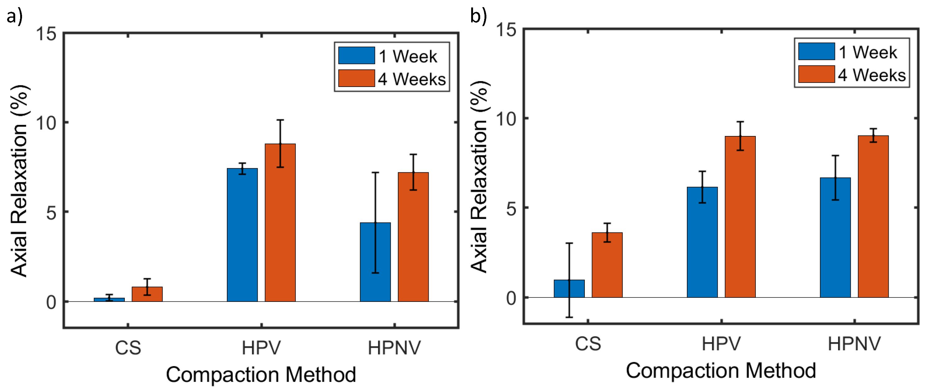
2.2.5. Axial Relaxation Measurements

Axial relaxation (R) was measured for pellets compacted at 159 MPa for all materials and compaction methods. Pellet thickness was measured using a micrometer ( ± 0.005 mm ) immediately after compaction, one and four weeks after compaction. Using the thicknesses measured one week ( L 1 ) and four weeks ( L 4 ) after compaction, the axial relaxation was calculated as a percentage of the post-compaction thickness.
R = ( 100 ( L ( 1 , 4 ) / L ( p c ) ) ) 100

2.2.6. Tensile Strength Measurements

The breaking force of each pellet was measured using a high load hardness tester (Kraemer Elektronick HC6.2, Darmstadt Germany). Utilising the extracted breaking force value, h and sample diameter (D), the tensile strength, σ t , for the pellets was then calculated:
σ t = 2 h π D L

3. Results

3.1. Gas Pycnometery Measurements

Pycnometric density ( ρ t r u e ) for all polymer materials is presented in Table 2. The measured values were the same as those provided by the manufacturers, with the exception of PTFE, which was lower.

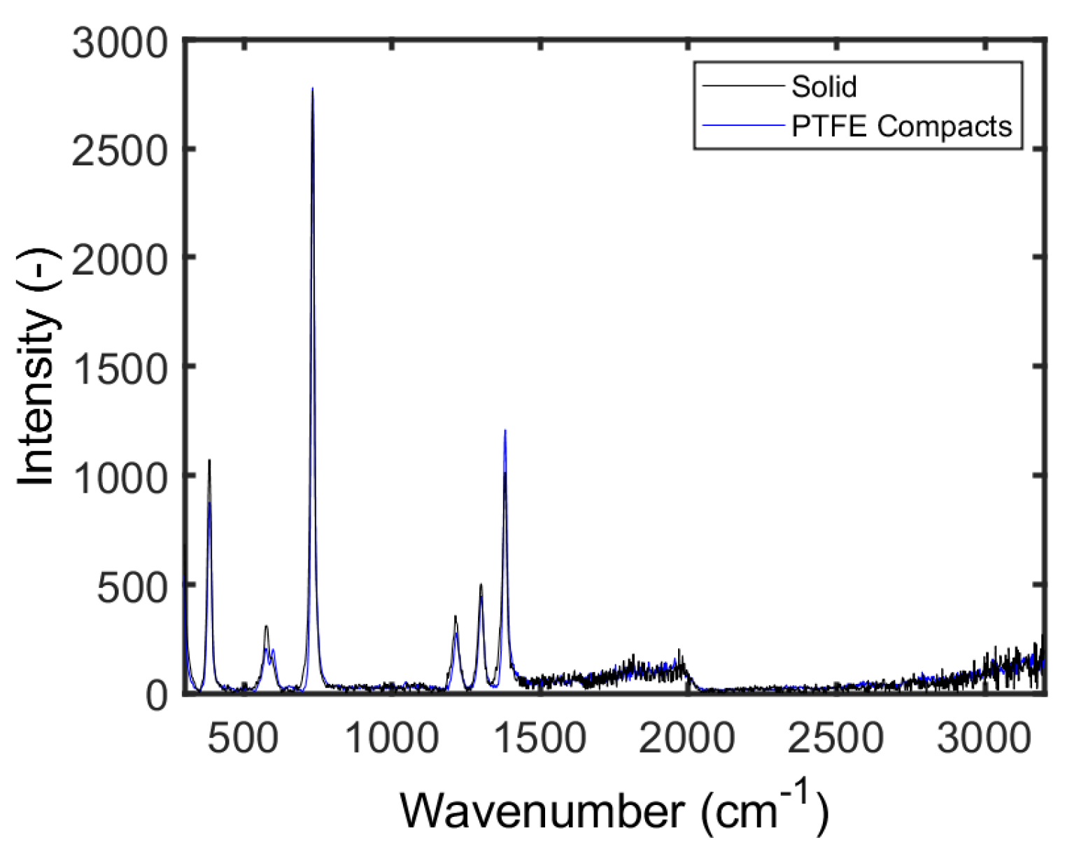
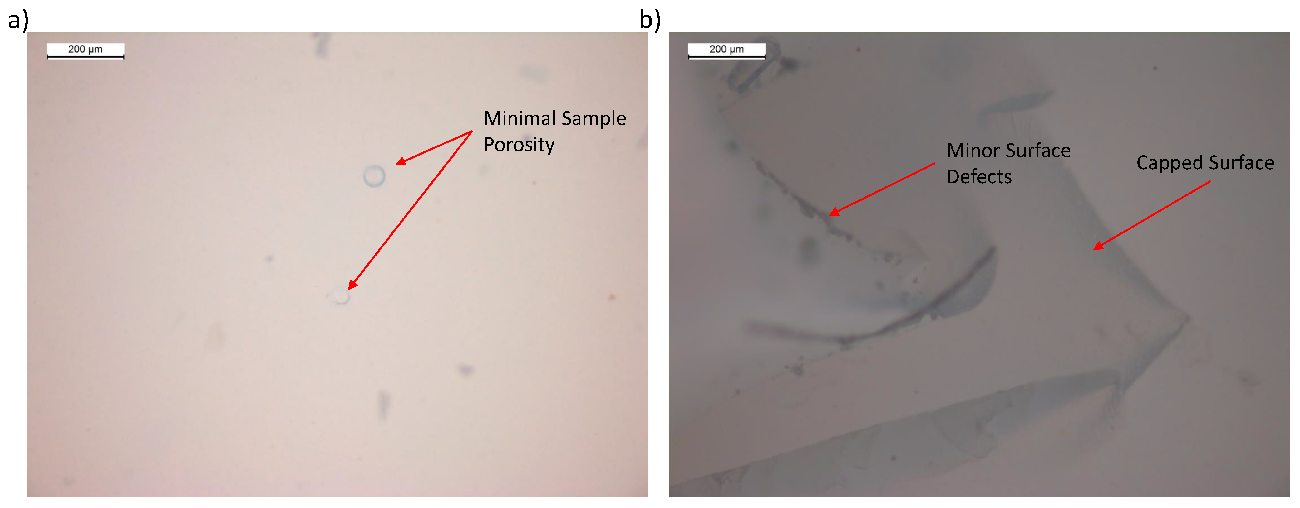
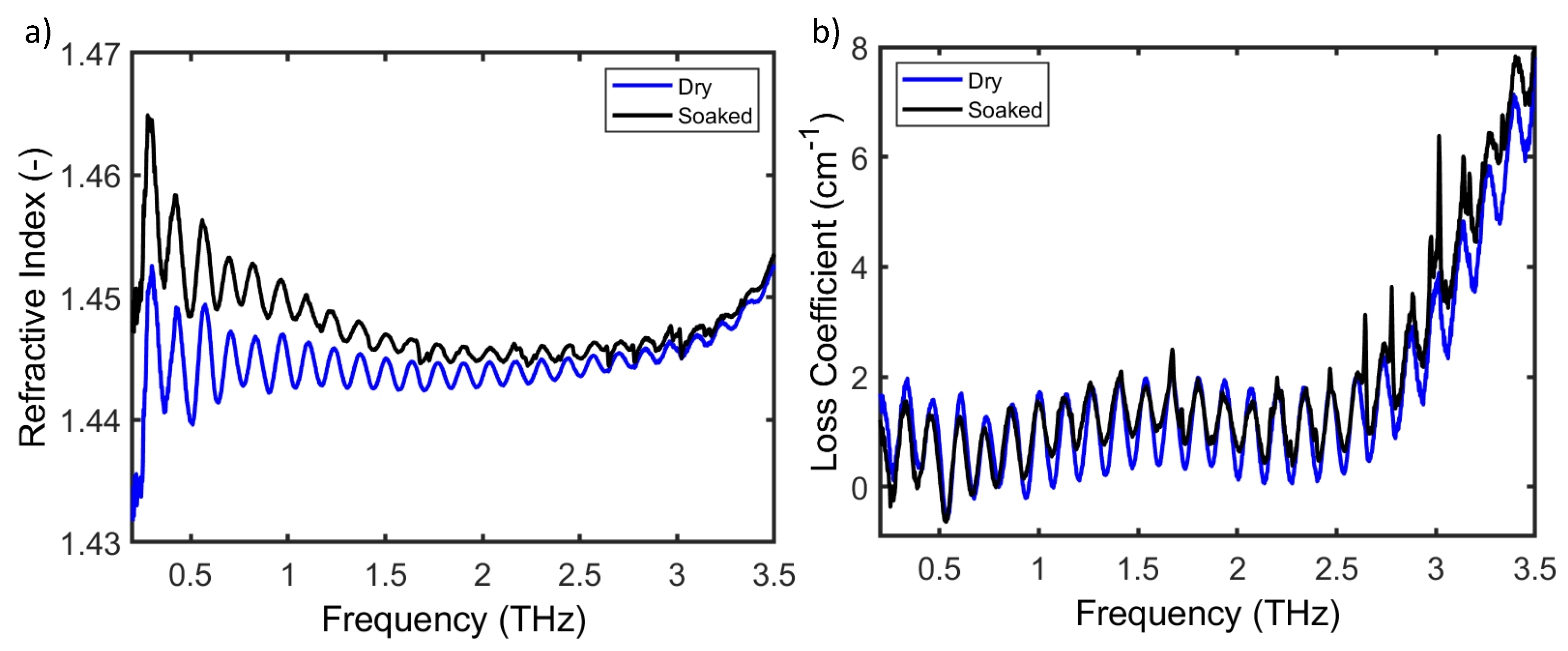
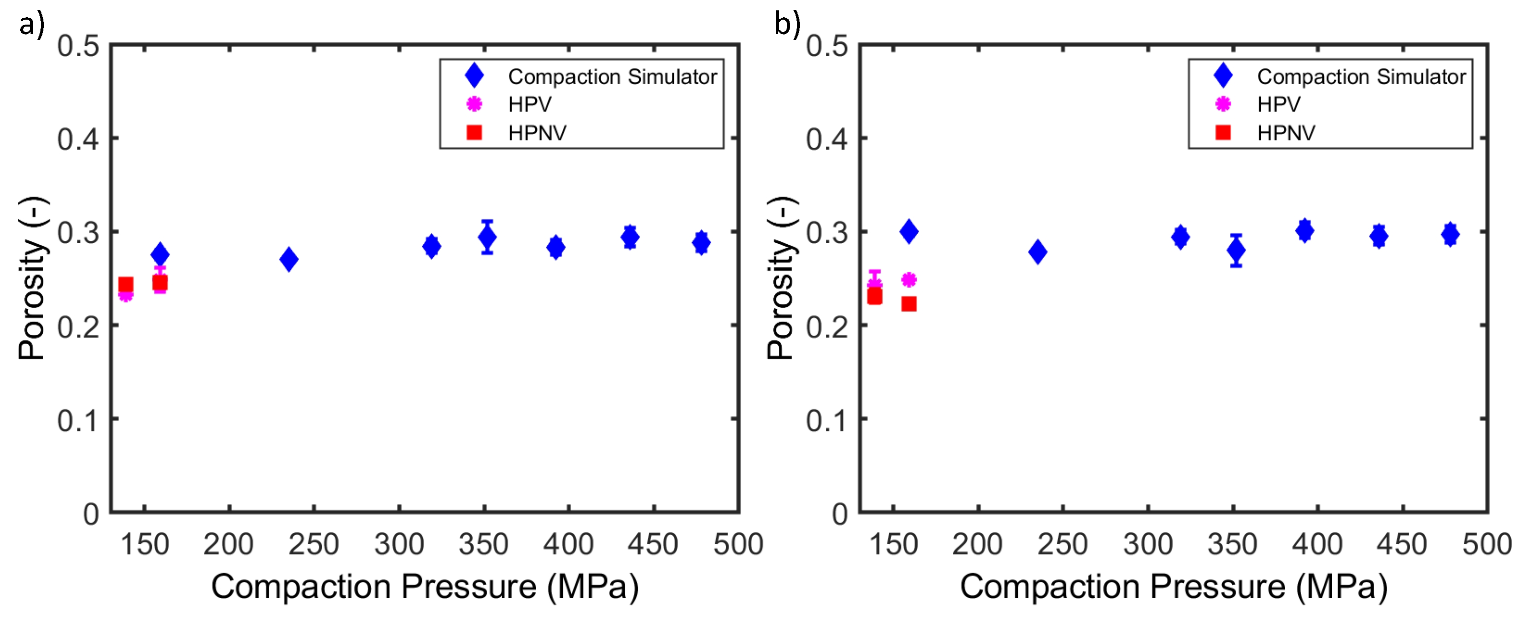
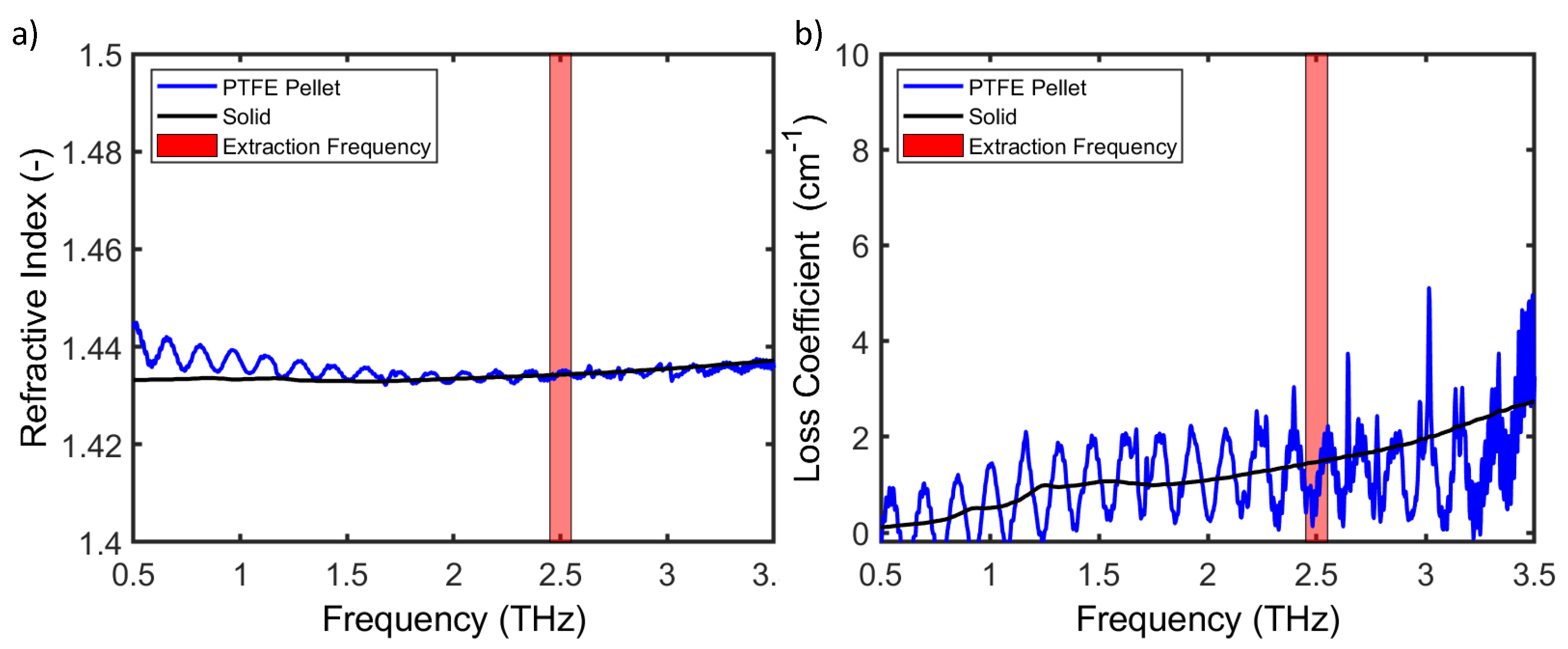
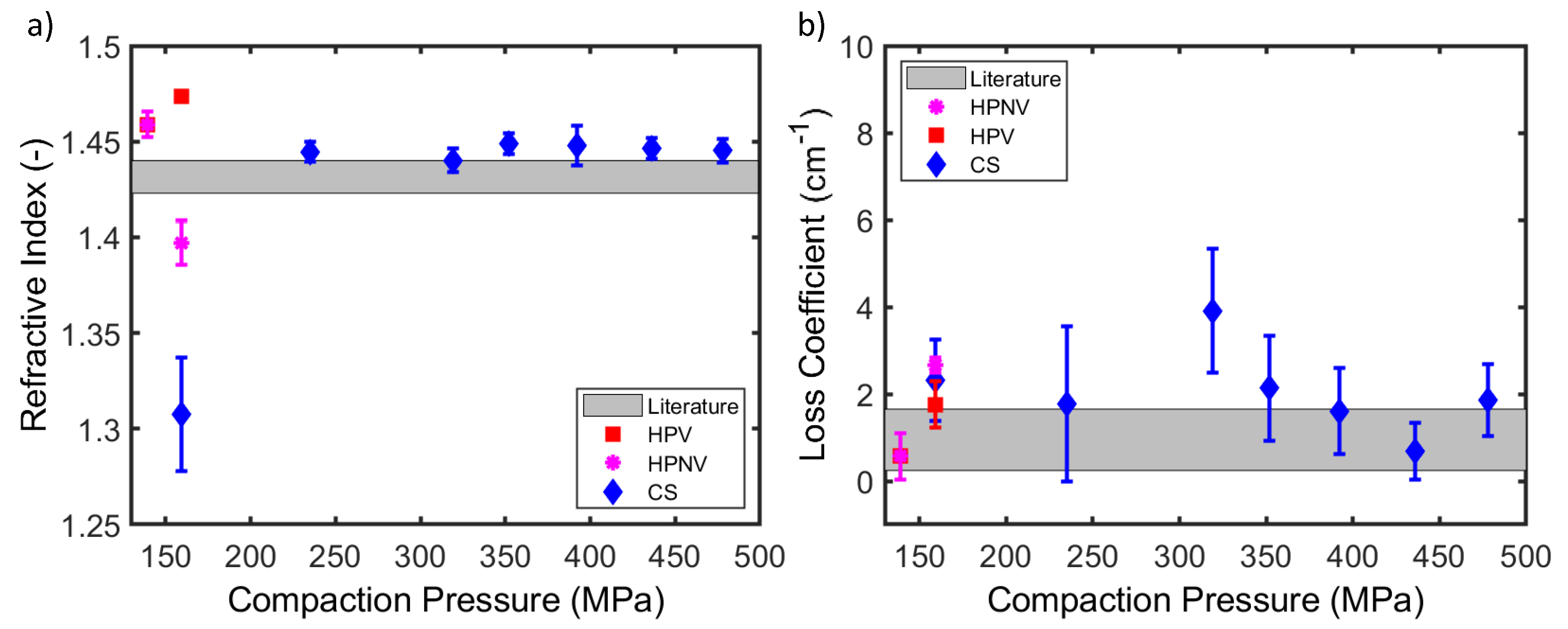
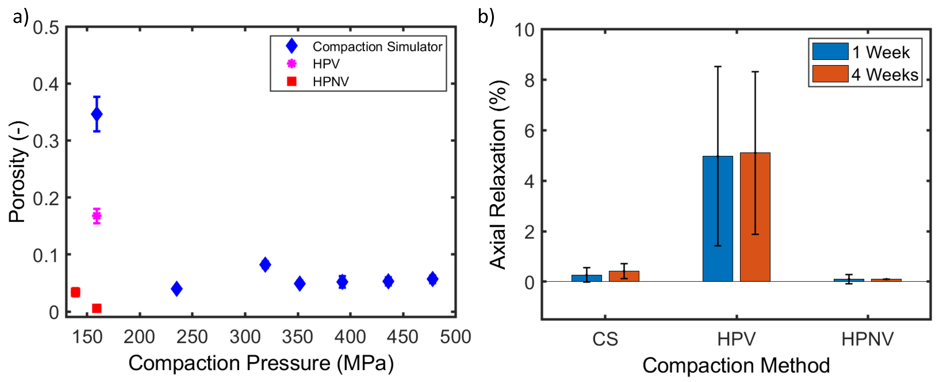
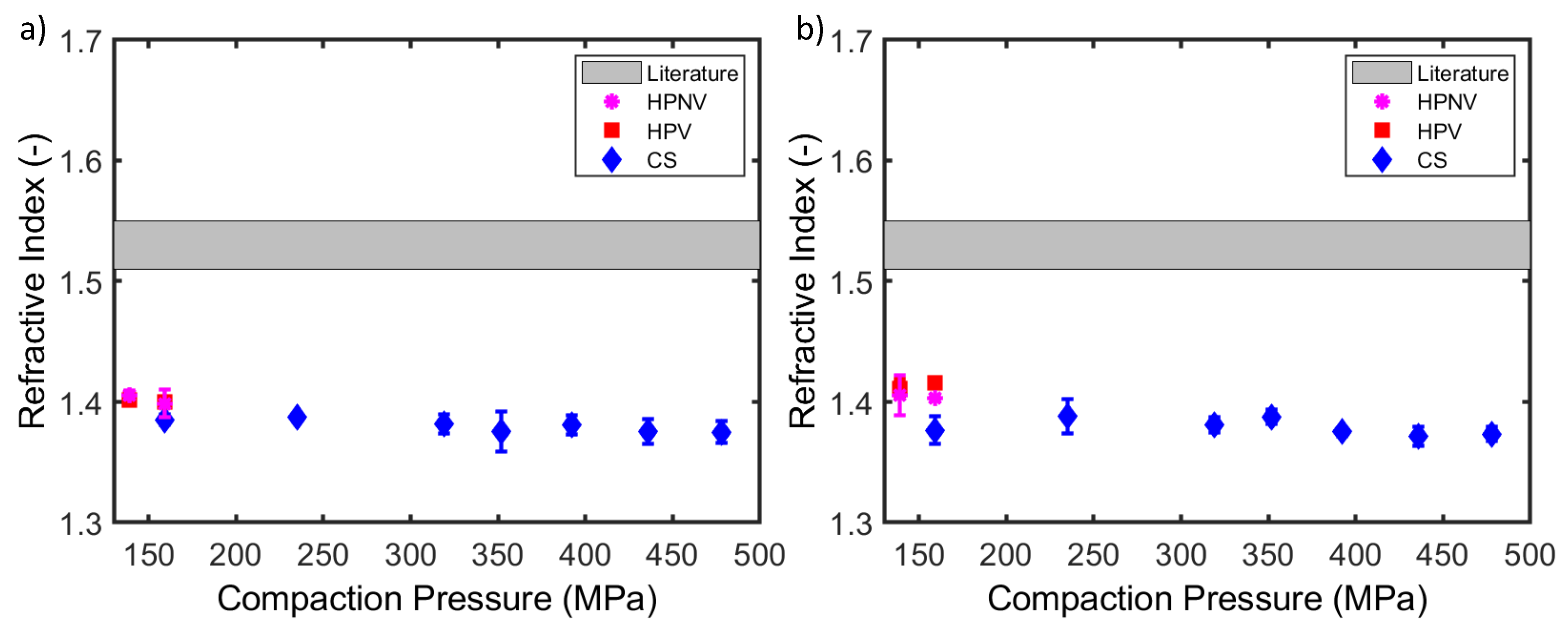
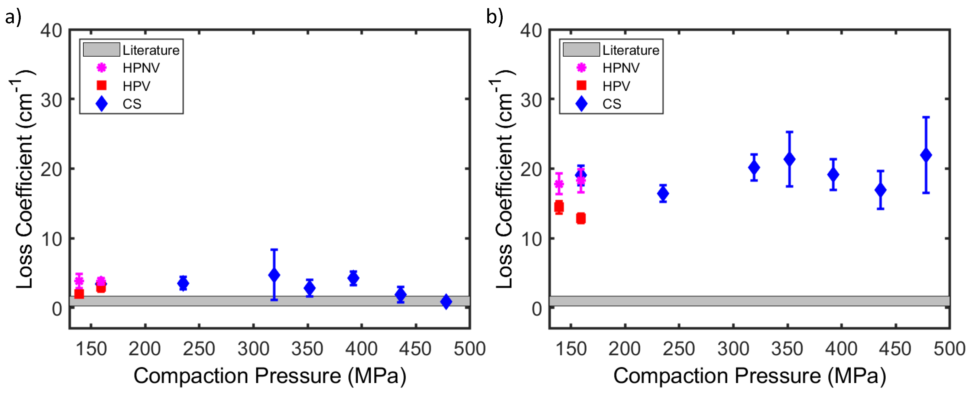
3.2. Polytetrafluoroethylene
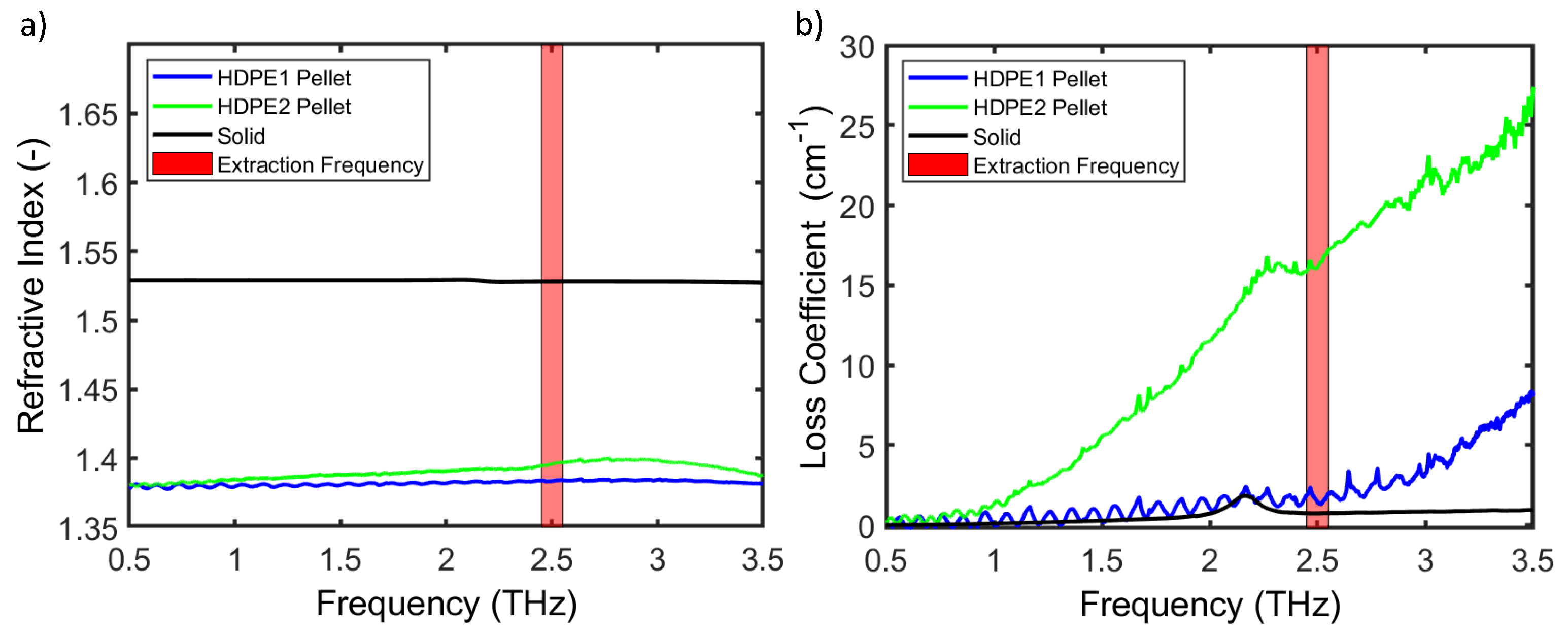
Full frequency spectra for both refractive index and loss coefficient for PTFE can be seen in Figure 1. It is evident at low frequencies that the PTFE pellets are in good agreement with the loss coefficient of solid material whereas the refractive index is slightly higher. Oscillations in the pellet spectra are artifacts due to internal reflections within the sample producing a Fabry–Perot effect. The oscillation period or free spectral range ( F S R ) is determined by the sample thickness and refractive index, given by [26,27]:
F S R = c 2 n extracted L
For the purposes of subsequent analysis, mean values over a range (2.45–2.55 THz) were used due to the lack of spectral features and relatively high signal-to-noise ratio (SNR).
Figure 2 presents the refractive index (a) and loss coefficient (b) of PTFE pellets compacted at various pressures (159, 235, 319, 352, 392, 436 and 478 MPa). The refractive indices of pellets made using the compaction simulator (Figure 2a) are either in good agreement or slightly above the values in the literature with the exception of the pellets that were compacted at a pressure of 159 MPa. Consistently higher refractive index values suggest a difference in material density compared with the values in the literature. Raman spectra of the PTFE pellets and solid reference samples were acquired to determine whether a change in amorphous or crystalline character had occurred (Figure A1); no such change was observed. Therefore, the increased refractive index is attributed to the different production method used for the powder compared with that for the solid polymer.
The loss coefficient values for compaction pressures > 350 MPa are within the reference ranges. It can also be observed that higher compaction pressures lead to more consistent loss coefficient values. The refractive index value at a compaction pressure of 159 MPa is significantly lower than expected and exhibits high variability across ten pellets. This lower refractive index suggests a large sample porosity created by inter-particle pores. These inter-particle pores reduce in size with increasing compaction pressure. The measured RI approaches the refractive index of the solid material as the porosity decreases with increasing compaction pressure. Evidence of sample cracks can be observed in microscope images (Figure A2b). The high calculated standard deviation is due to cracks in the samples produced at this lower pressure, particularly noticeable in those made using the compaction simulator. These cracks cause inaccuracies in the determination of the calculated refractive index due to changes in sample thickness. The cracks in these samples also affect the loss coefficient, which is higher in samples compacted at lower pressures.
The samples fabricated using the hydraulic press with a vacuum had refractive indices either slightly above or in agreement with the values in the literature. Loss coefficient values were also in good agreement with the values in the literature. However, it should be noted that creating samples in such a die requires care when releasing the pressure to prevent sample cracking. The dwell time difference between the compaction methods must also be considered where the hydraulic press had a larger dwell time compared with the compaction simulator, thus explaining the better performance at lower pressures. The increased loss coefficient for pellets produced at lower compaction pressures with the compaction simulator is driven by increased scattering from pores within the sample.
The hydraulic press without a vacuum performed well at 139 MPa, with both refractive index and loss coefficient values either matching or slightly above literature values. However, the samples produced using a compaction pressure of 159 MPa have a significantly lower refractive index, suggesting either an increase in sample porosity or the inclusion of structural defects in the sample. These structural defects are also seen in the increased loss coefficient in Figure 2.
A sample porosity for PTFE pellets produced using the compaction simulator and the hydraulic press at all compaction pressures is shown in Figure 3a. The ZPA was employed to calculate sample porosity from refractive index. An additional investigation into the sample porosity of PTFE pellets involved THz-TDS analysis of dry and paraffin oil soaked pellets. The paraffin oil will fill surface connected pores and increase the refractive index due to a decrease in sample porosity. This investigation suggested minimal open (surface connected) pores (Figure A3) [14]. As PTFE is opaque to visible light, microscope imaging can be deployed to identify pores close to the sample surface. Microscope imaging of PTFE samples compacted at >350 MPa showed minimal porosity (Figure A2). Furthermore, due to the refractive index values matching or exceeding that of solid PTFE, it is clear that these pellets have close to zero porosity, indicating that PTFE is a suitable material for fabricating compressed pellets with minimal porosity.
PTFE pellets fabricated in the compaction simulator and hydraulic press without a vacuum do not undergo significant axial relaxation one week after compaction (Figure 3b). Pellets fabricated in the hydraulic press with a vacuum (HPV) exhibit more significant axial relaxation between zero and one week after compaction. Therefore, due to the axial relaxation of PTFE pellets being negligible for those produced with the compaction simulator and the hydraulic press without a vacuum, it is clear that THz-TDS analysis can be carried out one week after compaction allowing for repeated analysis.

3.3. Polyethylene

The full frequency spectra for both refractive index and loss coefficient for HDPE can be seen in Figure 4. It is evident that the HDPE pellets contain significant porosity as the refractive index is significantly lower than that for the solid reference material. The HDPE2 pellets have much higher loss values due to increased scattering in materials comprising a larger particle size. As HDPE2 is more strongly absorbing, the Fabry–Perot oscillations are suppressed at higher frequencies because internal echoes are absorbed as they propagate through the material. The loss coefficient for the HDPE1 pellets are in good agreement with that of the solid reference material below 2 THz; however, higher frequencies are more affected by the scattering from particles, leading to significant excess loss above 1 THz. For the purposes of subsequent analysis, mean values over a range (2.45–2.55 THz) were used due to the lack of spectral features and relatively high SNR.
Refractive indices extracted at 2.45–2.55 THz for HDPE1 and HDPE2 are presented in Figure 5 as a function of compaction pressure. The results indicate that the refractive index for both HDPE grades is significantly lower than the literature values. The lower refractive index suggests significant porosity in all samples, meaning that the polymer is unsuitable for accurate determination of RI. Samples made with the hydraulic press show slightly higher refractive indices than the compaction simulator; this increase is independent of the application of a vacuum. There is no distinguishable difference in RI between samples of the two grades.
Loss coefficients for HDPE1 (a) and HDPE2 (b) are presented in Figure 6 as a function of compaction pressure. The loss coefficient for HDPE1 grade is in good agreement with the reference loss coefficient values, indicating low scattering. However, pellets made from HDPE2 exhibit significantly higher loss, which is attributed to increased scattering from the larger particle size. The loss coefficient remains constant because porosity is constant over the compaction pressure range (Figure 7 and Figure 8). The reproducibility of samples produced using the hydraulic press is higher than those fabricated in the compaction simulator (Figure 6). The variation is significantly higher for pellets produced at compaction pressures > 350 MPa, suggesting that compaction pressures > 350 MPa are unsuitable for sample preparation of this material.
The sample porosity for the HDPE pellets produced using the compaction simulator and the hydraulic press across all compaction pressures is shown in Figure 7a. The ZPA was employed to calculate sample porosity from the refractive index. The HDPE1 samples increase in porosity with increasing compaction pressure, whereas the HDPE2 samples have more consistent porosity values. It is evident that these porosity values are too large for the extraction of accurate THz optical parameters. The inclusion of pores reduces the calculated effective refractive index and the pores’ scattering leads to an increased loss coefficient value.
The HDPE pellets undergo significantly more axial relaxation one week after compaction (Figure 8) compared with that of PTFE pellets. Axial relaxation in HDPE samples continues to 4 weeks after compaction, with samples made using the hydraulic press (longer dwell times) showing more significant relaxation. The application of a vacuum leads to significantly more elastic relaxation in HDPE1 (lower particle size) compared with HDPE2 (higher particle size). It is evident that particle size has a significant effect on the axial relaxation. Larger particle sizes will relax to a greater extent and show more significant differences between one and four weeks after compaction. Therefore, due to the axial relaxation of HDPE being significant for pellets produced using all compaction methods, it is clear that THz-TDS analysis should be carried out four weeks after compaction allowing for repeated analysis.
In summary, the samples produced by all compaction methods show significant porosity, making them unsuitable for the accurate extraction of refractive index or loss coefficient values.

3.4. Tensile Strength

The tensile strengths of pellets of all grades compacted at 392 MPa were determined, showing a distinct difference in the strength of the pellets (Table 3). PTFE and HDPE1 pellets exhibit significantly higher tensile strength than HDPE2 pellets. This difference cannot be attributed to porosity since porosity values of the two grades are similar within error (Figure 7). This change in tensile strength can be attributed to the different particle size. For HDPE, small particle sizes would be preferable for sample preparation, both in terms of tensile strength and reduced scattering. As both PTFE and HDPE1 have tensile strengths higher than 2 MPa, they would both be suitable for experimental handling, provided that they are compacted at >392 MPa. However it must be noted that the handling of HDPE1 was inferior to that of PTFE. It was observed that, during handling of HDPE1 pellets, the surface visibly crumbled and left residue on gloves, meaning repeated analysis of samples would lead to lower reproducibility.

4. Discussion

The results demonstrate that PTFE is preferred over HDPE for use as a matrix material due to the lower porosity of PTFE pellets. The PTFE samples have a high tensile strength, indicating that they are structurally robust when compacted at >392 MPa, allowing for repeated analysis and ease of handling.
The optimal compaction pressure for fabricating PTFE samples with the compaction simulator appears to be greater than 350 MPa to avoid lamination or capping. However, a lower compaction pressures should be used with a hydraulic press if the operator controlled pressure release is well regulated to prevent the sample from being broken. The dwell time utilised by the compaction methods must also be considered, as a lower compaction pressure with a sufficiently long dwell time will achieve the same performance as a higher pressure with shorter a dwell time.
The particle size of the material has a significant effect on tensile strength, axial relaxation, sample porosity and scattering (Figure 7). Smaller particle sizes would be preferable for scattering reduction and higher tensile strength.
Comparing the performance of the compaction simulator and hydraulic press suggests that the hydraulic press is superior in creating lower porosity samples. This is primarily driven by the effect of dwell time as the compaction simulator was set to a shorter dwell time compared with the hydraulic press where the operator directly controls the dwell time. No noticeable advantage was observed by applying a vacuum to the die (Figure 7) in regards to the final porosity values. This is attributed to the axial relaxation after compaction, as a higher compaction pressure causes more significant axial relaxation [32] and greater changes in porosity. Analysis immediately after compaction is not recommended as changes in porosity will lead to a reduced reproducibility. However, utilising a vacuumed die for PTFE samples would be the preferred choice for minimising the effect of porosity if THz-TDS analysis must be carried out immediately after compaction and repeated analysis is not required.
Finally, there is a significant difference between the optical parameters extracted from the two HDPE grades. It is therefore advisable to create reference samples of pure matrix polymer for each batch of material.

5. Conclusions

We investigated the fabrication of polymer pellets for the accurate measurement of THz parameters. PTFE and HDPE pellets were created using various compaction pressures; measurements for THz-TDS, tensile strength, axial relaxation and porosity were performed. Three compaction methods were used to assess their performance: hydraulic press with and without a vacuum, as well as a compaction simulator. We also investigated two different grades of HDPE to assess uniformity between grades and the effect of particle size.
PTFE was the preferred material for use as a matrix due to its low porosity and high tensile strength. It was found that a compaction pressure > 350 MPa was required to prevent lamination/capping in compaction simulator samples. HPDE grades produce samples with significant porosity at all compaction pressures, making refractive index and loss coefficient extraction less accurate. There were noticeable differences in the extracted optical parameters between grades of HDPE, suggesting that inter-batch material variations reinforce the need for reference samples to be created for each batch of polymer. The particle size in HDPE primarily affected the resulting tensile strength and scattering loss of the material, with smaller particles producing pellets with higher tensile strength and lower loss coefficients. Pellets can increase in thickness after compaction for up to four weeks, meaning that THz-TDS analysis should be carried out after this period to ensure reproducible results.
Compaction using the hydraulic press resulted in noticeably superior samples, with a vacuum providing no noticeable benefits with the exception of reduced porosity in PTFE pellets immediately after compaction. This performance improvement is primarily due to an increase in dwell time compared with that used for the compaction simulator [33]. The ability to control the aspects of compaction in the simulator, and recording of the in-die parameters such as thickness and diameter provide distinct advantage.

Author Contributions

Conceptualization, K.N.M., M.N. and D.M.; methodology, K.N.M., M.N. and D.M.; software, K.N.M. and D.M.; validation, K.N.M., M.N. and D.M.; formal analysis, K.N.M., M.N. and D.M.; investigation, K.N.M., M.N. and D.M.; resources, K.N.M., M.N. and D.M.; data curation, K.N.M.; writing—original draft preparation, K.N.M.; writing—review and editing, M.N., D.M. and A.N.; visualization, K.N.M., M.N. and D.M.; supervision, M.N., D.M. and A.N.; project administration, K.N.M.; funding acquisition, M.N., A.N. and D.M. All authors have read and agreed to the published version of the manuscript.

Funding

This research was funded by EPSRC and National Physical Laboratory through an industrial iCASE studentship (grant number: EP/S02168X/1). This research was carried out on an EPSRC (EP/S02168X/1) funded compaction simulator and terahertz time-domain spectrometer and in the CMAC National Facility supported by UKRPIF (UK Research Partnership Fund) award from the Higher Education Funding Council for England (HEFCE) (Grant Ref HH13054).

Institutional Review Board Statement

Not applicable.

Informed Consent Statement

Not applicable.

Data Availability Statement

The data presented in this study are openly available in the University of Strathclyde repository at https://doi.org/10.15129/600b7d06-0cac-4d9e-9b31-409fb82b16ae (accessed on 24 February 2022).

Conflicts of Interest

The authors declare no conflict of interest.

Appendix A

Figure A1. Raman spectra (Bruker Bravo, Billerica, Massachusetts, United States) of PTFE pellets and solid PTFE showing no changes in crystalline or amorphous character.
Applsci 12 03475 g0a1
Figure A2. Microscope images of PTFE pellets showing minimal sample porosity and capping evidence on the surface of pellets compacted at lower pressures. (a) PTFE pellet produced with a compaction pressure of 392 MPa with minimal sample porosity and (b) PTFE pellet produced with a compaction pressure of 235 MPa with surface imperfections/capping.
Applsci 12 03475 g0a2
Figure A3. THz-TDS optical parameters of the dry and paraffin soaked pellets. (a) refractive index and (b) loss coefficient.
Applsci 12 03475 g0a3

References

  1. Markl, D.; Sauerwein, J.; Goodwin, D.J.; van den Ban, S.; Zeitler, J.A. Non-destructive Determination of Disintegration Time and Dissolution in Immediate Release Tablets by Terahertz Transmission Measurements. Pharm. Res. 2017, 34, 1012–1022. [Google Scholar] [CrossRef] [PubMed] [Green Version]
  2. Zeitler, J.A.; Shen, Y.C. Terahertz Spectrscopy and Imaging, 1st ed.; Springer: Berlin, Germany, 2012; pp. 451–489. [Google Scholar] [CrossRef]
  3. Naftaly, M.; Vieweg, N.; Deninger, A. Industrial Applications of Terahertz Sensing: State of Play. Sensors 2019, 19, 4203. [Google Scholar] [CrossRef] [PubMed] [Green Version]
  4. Naftaly, M.; Miles, R.E. Terahertz time-domain spectroscopy for material characterization. Proc. IEEE 2007, 95, 1658–1665. [Google Scholar] [CrossRef]
  5. Shen, Y.C.; Jin, B.B. 20-Terahertz applications in the pharmaceutical industry. In Woodhead Publishing Series in Electronic and Optical Materials, Handbook of Terahertz Technology for Imaging, Sensing and Communications; Woodhead Publishing, 2013; Volume 5, pp. 579–614. Available online: https://www.sciencedirect.com/science/article/pii/B9780857092359500203 (accessed on 24 February 2022). [CrossRef]
  6. Pawar, A.Y.; Sonawane, D.D.; Erande, K.B.; Derle, D.V. Terahertz technology and its applications. Drug Invent. Today 2013, 5, 157–163. [Google Scholar] [CrossRef]
  7. Engelbrecht, S.; Tybussek, K.H.; Sampaio, J.; Böhmler, J.; Fischer, B.M.; Sommer, S. Monitoring the Isothermal Crystallization Kinetics of PET-A Using THz-TDS. J. Infrared Millim. Terahertz Waves 2019, 40, 306–313. [Google Scholar] [CrossRef]
  8. Sommer, S.; Raidt, T.; Fischer, B.M.; Katzenberg, F.; Tiller, J.C.; Koch, M. THz-Spectroscopy on High Density Polyethylene with Different Crystallinity. J. Infrared Millim. Terahertz Waves 2016, 37, 189–197. [Google Scholar] [CrossRef]
  9. Markl, D.; Strobel, A.; Schlossnikl, R.; Bøtker, J.; Bawuah, P.; Ridgway, C.; Rantanen, J.; Rades, T.; Gane, P.; Peiponen, K.E.; et al. Characterisation of pore structures of pharmaceutical tablets: A review. Int. J. Pharm. 2018, 538, 188–214. [Google Scholar] [CrossRef] [Green Version]
  10. Bawuah, P.; Markl, D.; Turner, A.; Evans, M.; Portieri, A.; Farrell, D.; Lucas, R.; Anderson, A.; Goodwin, D.J.; Zeitler, J.A. A Fast and Non-destructive Terahertz Dissolution Assay for Immediate Release Tablets. J. Pharm. Sci. 2020, 110, 2083–2092. [Google Scholar] [CrossRef]
  11. Bawuah, P.; Tan, N.; Tweneboah, S.N.A.; Ervasti, T.; Axel Zeitler, J.; Ketolainen, J.; Peiponen, K.E. Terahertz study on porosity and mass fraction of active pharmaceutical ingredient of pharmaceutical tablets. Eur. J. Pharm. Biopharm. 2016, 105, 122–133. [Google Scholar] [CrossRef]
  12. Da Silva, V.H.; Vieira, F.S.; Rohwedder, J.J.; Pasquini, C.; Pereira, C.F. Multivariate quantification of mebendazole polymorphs by terahertz time domain spectroscopy (THZ-TDS). Analyst 2017, 142, 1519–1524. [Google Scholar] [CrossRef]
  13. Jepsen, P.U.; Cooke, D.G.; Koch, M. Terahertz spectroscopy and imaging—Modern techniques and applications. Laser Photonics Rev. 2011, 5, 124–166. [Google Scholar] [CrossRef]
  14. Naftaly, M.; Tikhomirov, I.; Hou, P.; Markl, D. Measuring open porosity of porous materials using thz-tds and an index-matching medium. Sensors 2020, 20, 3120. [Google Scholar] [CrossRef] [PubMed]
  15. Smith, R.M.; Arnold, M.A. Terahertz time-domain spectroscopy of solid samples: Principles, applications, and challenges. Appl. Spectrosc. Rev. 2011, 46, 636–679. [Google Scholar] [CrossRef]
  16. Zeitler, J.A. Terahertz Spectroscopy and Imaging. In Terahertz Spectroscopy and Imaging, 1st ed.; Peiponen, K.E., Ed.; Springer: Berlin, Germany, 2016; pp. 171–222. [Google Scholar] [CrossRef]
  17. Pierno, L.; Fiorello, A.M.; Scafe, S.; Cunningham, J.; Burnett, A.D.; Linfield, E.H.; Davies, A.G. THz-TDS analysis of hidden explosives for homeland security scenarios. In Proceedings of the UCMMT 2013—2013 6th UK, Europe, China Millimeter Waves and THz Technology Workshop, Rome, Italy, 9–11 September 2013. [Google Scholar] [CrossRef]
  18. Özer, Z.; Gök, S.; Altan, H.; Severcan, F. Concentration-based measurement studies of L-tryptophan using terahertz time-domain spectroscopy (THz-TDS). Appl. Spectrosc. 2014, 68, 95–100. [Google Scholar] [CrossRef] [PubMed]
  19. Puc, U.; Abina, A.; Jeglič, A.; Zidanšek, A.; Kašalynas, I.; Venckevičius, R.; Valušis, G. Spectroscopic analysis of melatonin in the terahertz frequency range. Sensors 2018, 18, 4098. [Google Scholar] [CrossRef] [Green Version]
  20. Withayachumnankul, W.; Naftaly, M. Fundamentals of measurement in terahertz time-domain spectroscopy. J. Infrared Millim. Terahertz Waves 2014, 35, 610–637. [Google Scholar] [CrossRef]
  21. Bawuah, P.; Markl, D.; Farrell, D.; Evans, M.; Portieri, A.; Anderson, A.; Goodwin, D.; Lucas, R.; Zeitler, J.A. Terahertz-Based Porosity Measurement of Pharmaceutical Tablets: A Tutorial. J. Infrared Millim. Terahertz Waves 2020, 41, 450–469. [Google Scholar] [CrossRef] [Green Version]
  22. Sun, C.C. A material-sparing method for simultaneous determination of true density and powder compaction properties-Aspartame as an example. Int. J. Pharm. 2006, 326, 94–99. [Google Scholar] [CrossRef]
  23. Wu, C.Y.; Hancock, B.C.; Mills, A.; Bentham, A.C.; Best, S.M.; Elliott, J.A. Numerical and experimental investigation of capping mechanisms during pharmaceutical tablet compaction. Powder Technol. 2008, 181, 121–129. [Google Scholar] [CrossRef]
  24. Neu, J.; Schmuttenmaer, C.A. Tutorial: An introduction to terahertz time domain spectroscopy (THz-TDS). J. Appl. Phys. 2018, 124–125. [Google Scholar] [CrossRef] [Green Version]
  25. Jepsen, P.U. Phase Retrieval in Terahertz Time-Domain Measurements: A “how to” Tutorial. J. Infrared Millim. Terahertz Waves 2019, 40, 395–411. [Google Scholar] [CrossRef] [Green Version]
  26. Duvillaret, L.; Garet, F.; Coutaz, J.L. A reliable method for extraction of material parameters in terahertz time-domain spectroscopy. IEEE J. Sel. Top. Quantum Electron. 1996, 2, 739–745. [Google Scholar] [CrossRef] [Green Version]
  27. Duvillaret, L.; Garet, F.; Coutaz, J.L. Highly precise determination of optical constants and sample thickness in terahertz time-domain spectroscopy. Appl. Opt. 1999, 38, 409. [Google Scholar] [CrossRef]
  28. Busch, S.F.; Weidenbach, M.; Fey, M.; Schäfer, F.; Probst, T.; Koch, M. Optical Properties of 3D Printable Plastics in the THz Regime and their Application for 3D Printed THz Optics. J. Infrared Millim. Terahertz Waves 2014, 35, 993–997. [Google Scholar] [CrossRef]
  29. D’Angelo, F.; Bonn, M.; Gente, R.; Koch, M.; Turchinovich, D. Ultra-broadband THz time-domain spectroscopy of common polymers with THz air-photonics. In Proceedings of the Conference on Lasers and Electro-Optics Europe-Technical Digest, San Jose, CA, USA, 3–4 January 2014; pp. 2924–2926. [Google Scholar] [CrossRef] [Green Version]
  30. Yamamoto, K.; Yamaguchi, M.; Tani, M.; Hangyo, M.; Teramura, S.; Isu, T.; Tomita, N. Degradation diagnosis of ultrahigh-molecular weight polyethylene with terahertz-time-domain spectroscopy. Appl. Phys. Lett. 2004, 85, 5194–5196. [Google Scholar] [CrossRef] [Green Version]
  31. Wietzke, S.; Jansen, C.; Reuter, M.; Jung, T.; Kraft, D.; Chatterjee, S.; Fischer, B.M.; Koch, M. Terahertz spectroscopy on polymers: A review of morphological studies. J. Mol. Struct. 2011, 1006, 41–51. [Google Scholar] [CrossRef]
  32. Bawuah, P.; Karttunen, A.P.; Markl, D.; Ridgway, C.; Korhonen, O.; Gane, P.; Zeitler, J.A.; Ketolainen, J.; Peiponen, K.E. Investigating elastic relaxation effects on the optical properties of functionalised calcium carbonate compacts using optics-based Heckel analysis. Int. J. Pharm. 2018, 544, 278–284. [Google Scholar] [CrossRef]
  33. Wünsch, I.; Friesen, I.; Puckhaber, D.; Schlegel, T.; Finke, J.H. Scaling tableting processes from compaction simulator to rotary presses—Mind the sub-processes. Pharmaceutics 2020, 12, 310. [Google Scholar] [CrossRef] [Green Version]
Figure 1. Refractive index (a) and loss coefficient (b) spectra of PTFE pellets. Oscillations in spectra are artifacts due to internal reflections.
Applsci 12 03475 g001
Figure 2. Refractive index (a) and loss coefficient (b) of PTFE pellets compacted at various pressures. Optical parameters were extracted at 2.45–2.55 THz. Three compaction methods were used: hydraulic press with a vacuum (HPV) and without a vacuum (HPNV) as well as a compaction simulator (CS). Literature values for both RI and loss coefficient are shown as a grey band. The literature is presented as a band reflecting the range of values quoted in the literature [8,28,29,30,31]. Values plotted are the mean, with the error bars depicting ± one standard deviation (n = 10).
Applsci 12 03475 g002
Figure 3. Sample porosity (a) and axial relaxation (b) of PTFE pellets. Three compaction methods were used: hydraulic press with a vacuum (HPV) and without a vacuum (HPNV), as well as a compaction simulator (CS). Values plotted are the mean with the error bars depicting ± one standard deviation (n = 10 (a), n = 3 (b)).
Applsci 12 03475 g003
Figure 4. Spectra of HDPE pellets showing the (a) refractive index and (b) loss coefficient. Oscillations in spectra are artifacts due to internal reflections.
Applsci 12 03475 g004
Figure 5. Refractive index extracted at 2.45–2.55 THz for (a) HDPE1 and (b) HDPE2 pellets compacted at various pressures. Three compaction methods were used: hydraulic press with a vacuum (HPV) and without a vacuum (HPNV) as well as a compaction simulator (CS). Reference values for RI are shown as a grey band. Values plotted are the mean with the error bars depicting ± one standard deviation (n = 10).
Applsci 12 03475 g005
Figure 6. Loss coefficient extracted at 2.45–2.55 THz for (a) HDPE1 (b) and HDPE2 pellets compacted at various pressures.Three compaction methods were used: hydraulic press with a vacuum (HPV) and without a vacuum (HPNV) as well as a compaction simulator (CS). Reference values for RI is shown as a grey band. Values plotted are the mean with the error bars depicting ± one standard deviation (n = 10).
Applsci 12 03475 g006
Figure 7. Sample porosity for (a) HDPE1 and (b) HDPE2 pellets compacted at 159 MPa. Three compaction methods were used: hydraulic press with a vacuum (HPV) and without a vacuum (HPNV) as well as a compaction simulator (CS). Values plotted are the mean with the error bars depicting ± one standard deviation (n = 10).
Applsci 12 03475 g007
Figure 8. Axial relaxation for (a) HDPE1 and (b) HDPE2 pellets compacted at 159 MPa. Three compaction methods were used: hydraulic press with a vacuum (HPV) and without a vacuum (HPNV) as well as a compaction simulator (CS). Values plotted are the mean with the error bars depicting ± one standard deviation (n = 3).
Applsci 12 03475 g008
Table 1. Three polymer materials used for pellet fabrication, with particle size and solid true density at 25 °C provided by the material supplier.
NameMaterialAvg. Particle Size (μm)Manufacturer True Density (g/cm 3 )
PTFEPTFE12.15
HDPE1PE420.94
HDPE2PE1250.94
Table 2. Solid true density of PTFE and the two HDPE grades. Measured values are the mean ± one standard deviation (n = 3).
NameManufacturer True Density (g/cm 3 ) ϱ true (g/cm 3 )
PTFE2.152.07 ± 0.01
HDPE10.940.96 ± 0.02
HDPE20.940.95 ± 0.01
Table 3. Tensile strength of PTFE, HDPE1 and HDPE2 pellets produced using the compaction simulator. Pellets were compacted at 392 MPa. Calculated values are the mean ± one standard deviation (n = 5).
NameTensile Strength (MPa)
PTFE3.162 ± 0.050
PTFE3.162 ± 0.050
HDPE20.846 ± 0.058
Publisher’s Note: MDPI stays neutral with regard to jurisdictional claims in published maps and institutional affiliations.

