Article

Accuracy Improvement of a Laser Diode-Based System for Measuring the Geometric Errors of Machine Tools

1
School of Mechanical Engineering, Dalian University of Technology, Dalian 116024, China
2
Key Laboratory for Micro/Nano Technology and System of Liaoning Province, Dalian University of Technology, Dalian 116024, China
*
Author to whom correspondence should be addressed.
Appl. Sci. 2022, 12(7), 3479; https://doi.org/10.3390/app12073479
Submission received: 24 February 2022 / Revised: 18 March 2022 / Accepted: 28 March 2022 / Published: 29 March 2022
(This article belongs to the Special Issue Precision Manufacturing and Intelligent Machine Tools)

Abstract

:
Active methods are proposed to improve the measurement accuracy of a compact laser diode-based (LD-based) system, which is designed to measure the geometric errors of machine tools. The LD has some advantages, such as a small size, low cost and high efficiency. However, the laser spot of the LD is elliptical and the stability in the output power of the LD is low, which limits the accuracy of the measurement system, where the LD is used as the laser source. An active shaping method is proposed to shape the elliptical laser spot of the LD without adding additional optical elements. In addition, the laser beam drifts, including the linear drift and angular drift, are compensated in real-time by a proposed improved active error compensator, which consists of two drift feedback units and a Backpropagation Neural Networks-based PID controller, during the long-distance measurement. A series of experiments were conducted to verify the effectiveness of the proposed methods and the capability of the constructed LD-based system.

1. Introduction

The manufacturing accuracy of machine tools is seriously influenced by the inevitable geometric errors of the linear stages. Error compensation technology has been widely used as a cost-effective way to reduce the effects of the geometric errors [1,2,3]. As an important premise of the error compensation, the accuracy of the measurement approaches for detecting the geometric errors directly influence the compensation results.
Currently, there are some approaches for measuring the geometric errors of machine tools, such as laser ball bars [4,5], laser trackers [6,7], laser interferometers [8,9] and the techniques based on the principles of laser collimation (LC) and laser autocollimation (LA) [10,11,12,13,14] and so on. Among these techniques, the simplest and most on-line applicable one is to detect the position variation of the laser spot with respect to the photodetector based on the principles of LC and LA, which take advantage of the high sensitivity, high accuracy and simple computation. In order to reduce the size of the measurement system and realize the on-line measurement, a laser diode (LD), which has the advantages of miniaturization and low cost, is always adopted as the laser source of the measurement system [10,11,12].
The most commonly used normalization and differential algorithm of the photodetector in the measurement system based on the principles of LC and LA is derived from an ideal circular laser spot with a uniform distribution of the intensity. However, the shape and the intensity distribution of the LD is actually elliptical and have a Gauss distribution, which will affect the measurement accuracy. There are many researchers focusing on establishing compensation models for the circular laser spot with a Gauss distribution [15,16]. However, those models cannot be used for the elliptical laser spot. Laser beam shaping is one of the most cost-effective approaches to eliminate the measurement error caused by the laser spot characteristic of the LD. However, the traditional laser beam shaping methods require a set combination of lens [17], or a lens with a special shape [18], or some additional optical elements, such as a single-mode optical fiber [19], which will make the measurement system complex and unstable. How to reduce the effect of the elliptical laser spot without adding additional optical elements will have a positive effect on further improving the measurement accuracy of the LD-based system.
In addition, the LD has inevitable laser beam drifts, including a linear drift and an angular drift, which will influence the stability, the accuracy and the repeatability of the measurement system. The laser beam drifts can be reduced and compensated by integrating a beam expander [20] or establishing a passive common path in the measurement system [21,22]. An optical fiber can also be used to reduce the beam drift [23]. A special mechanism with a piezoelectric actuator can also be integrated into the system to actively compensate the laser beam drifts [10,11,24]. However, most of the above-mentioned methods only compensate the angular drift and only the laser beam drifts near the laser source can be compensated. The laser beam drifts in the long-distance measurement are not considered. Moreover, the linear drift is also not considered.
To address the above-mentioned problems, an active shaping method is firstly proposed for shaping the elliptical laser spot of the LD without adding additional optical elements in an LD-based system, which is constructed to measure the geometric errors of machine tools. An improved active error compensator is then designed to reduce the linear drift and the angular drift of the laser source during the long-distance measurement. The principles of the proposed active methods will be introduced in the following sections.

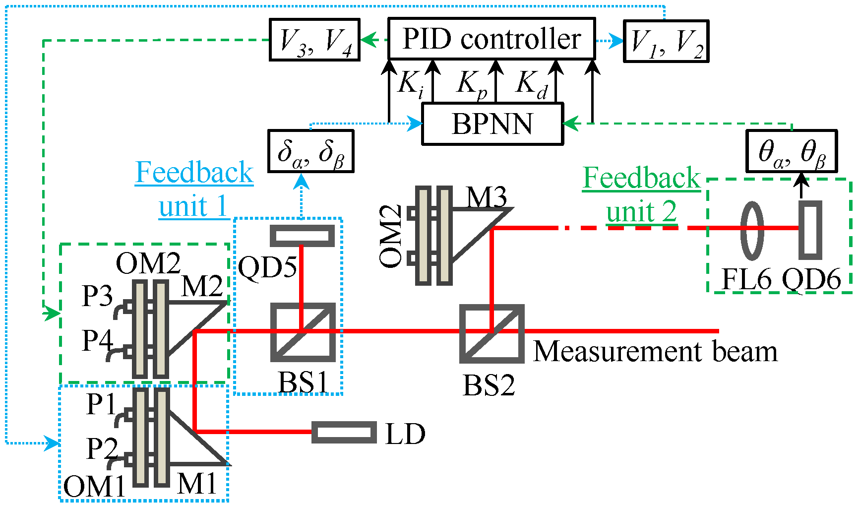
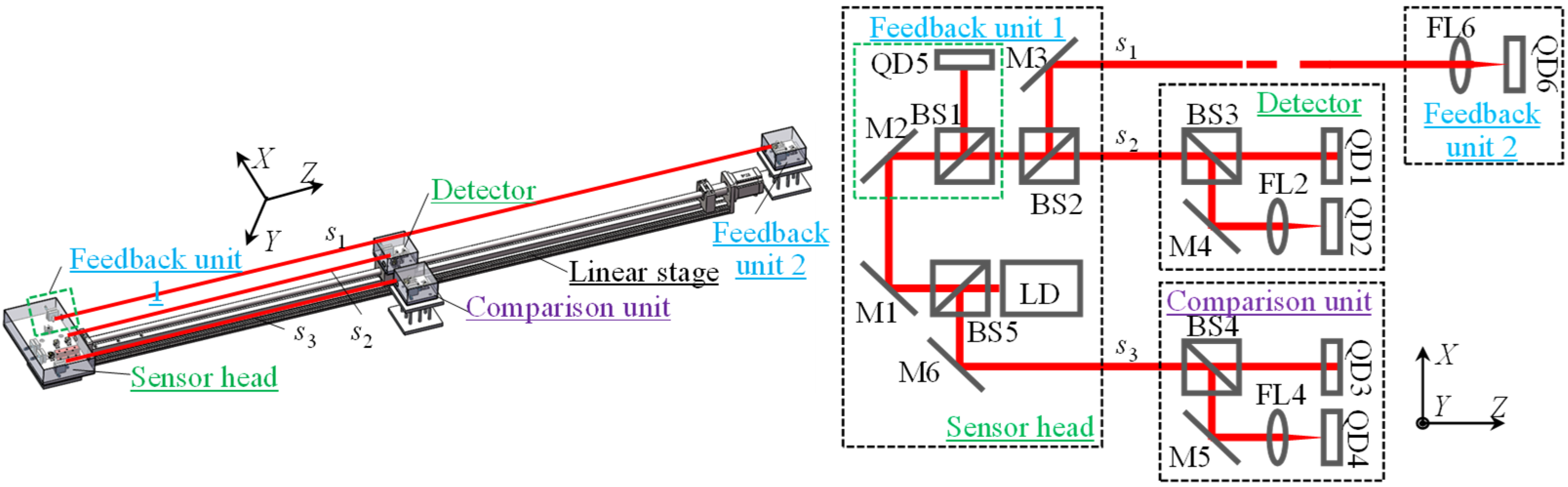
2. Measurement System

Figure 1 shows the schematic of the LD-based system for detecting the geometric errors of machine tools, including a horizontal straightness error δx, a vertical straightness error δy, a pitch error θx and a yaw error θy. The measurement system is composed of a sensor head and a detector.
A laser beam emitted from an LD is divided into two beams by a beam splitter (BS) after being bent by a mirror (M1). The reflected beam is projected onto a quadrant photodetector (QD1) for measuring δx and δy. The transmitted beam is bent by a mirror M2 and projected onto QD2 after being focused by a focus lens (FL) for measuring θx and θy. When the stage has error motions in δx and θx, the center of QD1 and QD2 will be shifted (Δx1 and Δx2) with respect to the laser beam. Therefore, δx and θx can be obtained by:
{ δ x = Δ x 1 = K δ x ( I A 1 + I D 1 ) ( I B 1 + I C 1 ) I A 1 + I B 1 + I C 1 + I D 1 θ x = Δ x 2 f = K θ x ( I A 2 + I D 2 ) ( I B 2 + I C 2 ) ( I A 2 + I B 2 + I C 2 + I D 2 ) f ,
where Kδx and Kθx represent the X-directional sensitivities of QD1 and QD2, respectively, which can be obtained by the calibrations. Im-i (m = A, B, C and D; I = 1, 2) represents the output current of each quadrant of QD1 and QD2, respectively, and f is the focal length of the FL.

3. Factors Affecting Accuracy and Accuracy-Improvement Methods

Since the LD is adopted as the laser source of the measurement system, it is essential to compensate and eliminate the measurement errors caused by the elliptical laser spot and the low stability in the output beam of the LD.

3.1. Effect of the Laser Spot Characteristic of the LD

Usually, the laser spot that projects onto a QD is approximated as a circular spot with a Gaussian intensity distribution. The intensity distribution of the laser beam can be described by:
I c ( x ,   y ) = I 0 exp [ 2 ( x 2 + y 2 ) r 2 ] ,
where I0 represents the light intensity of the centroid and r is the Gauss radius of the spot-intensity distribution.
Most of the LDs, however, have output elliptical laser spots with different beam radii rx and ry in the X and Y directions and an inclined angle φ with respect to the X axis. The ratio between rx and ry is defined as ellipticity e. The intensity distribution of the LD can be expressed by:
I e ( x ,   y ) = I 0 exp [ ( 2 ( x cos φ + y sin φ ) 2 r x 2 + 2 ( x sin φ + y cos φ ) 2 r x 2 e 2 ) ] ,
Using the normalization and differential algorithm of the photodetector to calculate δx and θx, the measurement errors (Δδx and Δθx) induced by the elliptical laser spot can be expressed by:
{ Δ δ x = Δ x c i r Δ x e l l = K δ x ( I A 1 + I D 1 ) ( I B 1 + I C 1 ) I A 1 + I B 1 + I C 1 + I D 1 K δ x e ( I A e 1 + I D e 1 ) ( I B e 1 + I C e 1 ) I A e 1 + I B e 1 + I C e 1 + I D e 1 Δ θ x = Δ x c i r f Δ x e l l f = 1 f ( K θ x ( I A 2 + I D 2 ) ( I B 2 + I C 2 ) ( I A 2 + I B 2 + I C 2 + I D 2 ) K θ x e ( I A e 2 + I D e 2 ) ( I B e 2 + I C e 2 ) ( I A e 2 + I B e 2 + I C e 2 + I D e 2 ) )
where Kδxe, Kθxe and Ime-i (m = A, B, C and D; i = 1, 2) represent the X-directional sensitivities and the output currents of QD1 and QD2 when an elliptical laser spot projects onto QD1 and QD2.
A group of simulations were first carried out to investigate the effect of the elliptical laser spot on the accuracy of the LD-based system. Figure 2 shows the effect of rx on Δδx and Δθx. e and φ were set to be 0.9 and 15°, respectively. The radii of the laser spots for measuring δx and θx were 2.5 mm and 5 μm, respectively, in the designed LD-based system. As can be seen from Figure 2a, Δδx was increased with the increase of rx. When rx and the command distance were set to be 2.5 mm and 200 μm, the maximum Δδx was evaluated to be 0.0038 μm, which was small enough and could be ignored. However, Δθx was increased with the decrease of the spot diameter, as shown in Figure 2b. As can be seen, the maximum Δθx was evaluated to be 11.25 arcsec when rx and the command angle were set to be 5 μm and 200 arcsec. Therefore, the effect of the elliptical laser spot on the measurement accuracy of the angular errors cannot be ignored. It was verified that the elliptical laser spot of the LD will affect the measurement accuracy of the angular errors but not affect that of the straightness errors.
Figure 3 shows the effects of e and φ on the angular error measurement accuracy. As can be seen from Figure 3, in which rx was set to be 5 μm, Δθx was increased as e and φ increased. φ and e were set to be 15°and 0.95, respectively, in Figure 3a,b. Therefore, in order to improve the angular error measurement accuracy of the LD-based measurement system, it is essential to shape the laser spot of the LD.
The X-directional and Y-directional diameters (dxf, dyf) of the focused laser spot on the QD, which is placed at the focal plane of the FL, can be expressed by:
d x f = 2.44 f λ 2 r x   =   2.44 f λ d x   and   d y f = 2.44 f λ 2 r y   =   2.44 f λ d y ,
where λ is the wavelength of the LD and dx and dy represent the X-directional and Y-directional diameters of the laser beam before focusing. If the QD is not located at the focal plane of the FL, the X-directional and Y-directional diameters (dxΔz, dyΔz) of the laser spot on the QD are revised to:
d x Δ z = d x f [ 1 + ( 4 λ Δ z π d x f 2 ) 2 ] 1 2   and   d y Δ z = d y f [ 1 + ( 4 λ Δ z π d y f 2 ) 2 ] 1 2 ,
where Δz is the position offset of the QD from the focal plane of the FL. As can be seen from Equation (6), a suitable Δz can be found so that dxΔz is equal to dyΔz. According to Equations (5) and (6), Δz can be expressed by:
Δ z = π d x f d y f 4 λ = 1.49 π λ f 2 d x d y ,
A simulation was conducted by setting dx, dy, λ and f to be 5.0 mm, 4.5 mm, 0.635 nm and 20 mm, respectively. It can be seen from the simulation results shown in Figure 4 that when Δz was set to be ±52.8 μm, dxΔz and dyΔz were both equal to 9.5 μm. It was verified that when the QD is located at a Δz distance from the focal plane of the FL, the elliptical laser spot can be shaped to be a circle laser spot.
It should be noted that the LD usually exits at a divergence angle α. The X-directional and Y-directional diameters (dxs, dys) of the laser spot at the random measurement position s will be varied to be:
d x s = d x + 2 s α   and   d y s = d y + 2 s α ,
When α is small enough, the influence of α on Δz and the diameter of the LD along the measurement direction can be ignored.

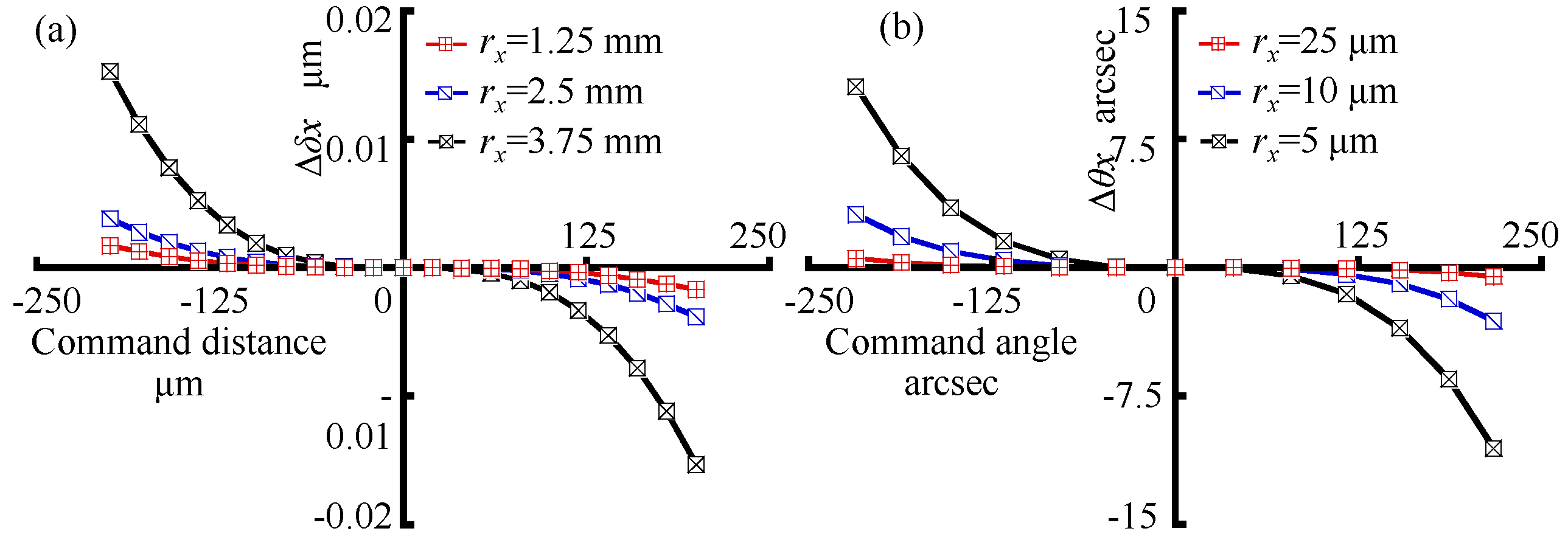
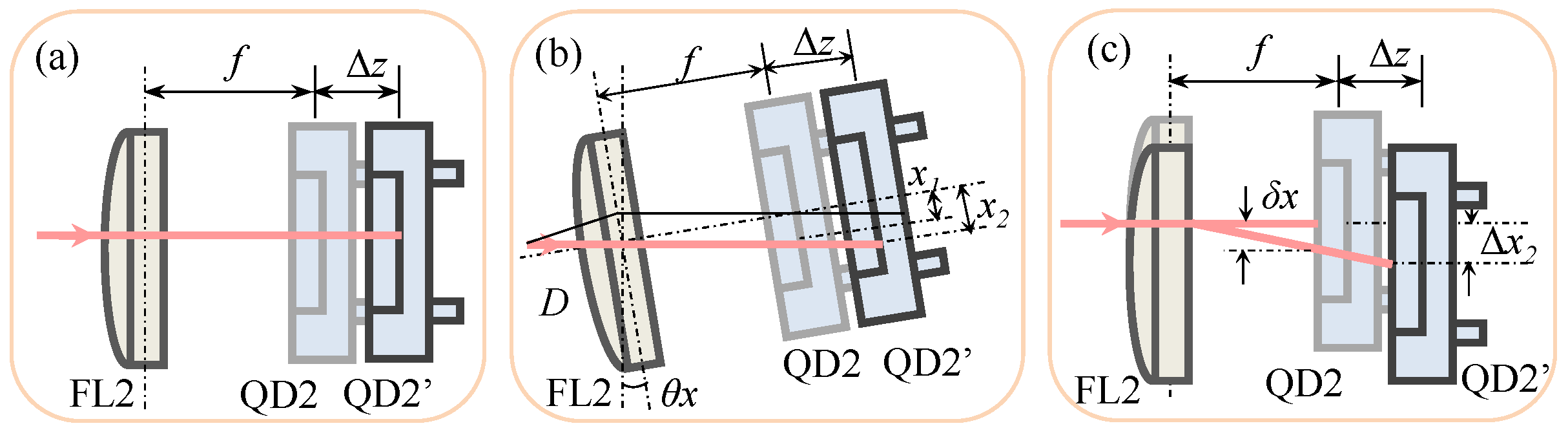
3.2. Effect of the Position Offset of the QD

Although the position offset Δz can reduce the measurement error caused by the elliptical laser spot of the LD, the defocus will also affect the angular error measurement accuracy. If the stage has no angular errors, Δz will not influence the QD output, as shown in Figure 5a. However, it can be seen from Figure 5b that Δz will induce measurement errors (Δθx1 and Δθy1) when the stage has angular errors (θx and θy). Δθx1 and Δθy1 can be derived by:
Δ θ x 1 = Δ z s f 2 θ x   and   Δ θ y 1 = Δ z s f 2 θ y ,
where s is the random measurement position, which is the distance between the detector and the sensor head.
In addition, the incident position of the laser beam on the FL will be varied by the straightness errors (δx and δy), as shown in Figure 5c. In this case, the existing of the position offset Δz will cause a QD output Δx2 and further induce measurement errors (Δθx2 and Δθy2). Δθx2 and Δθy2 can be derived by:
Δ θ x 2 = f + Δ z f δ x   and   Δ θ y 2 = f + Δ z f δ y ,

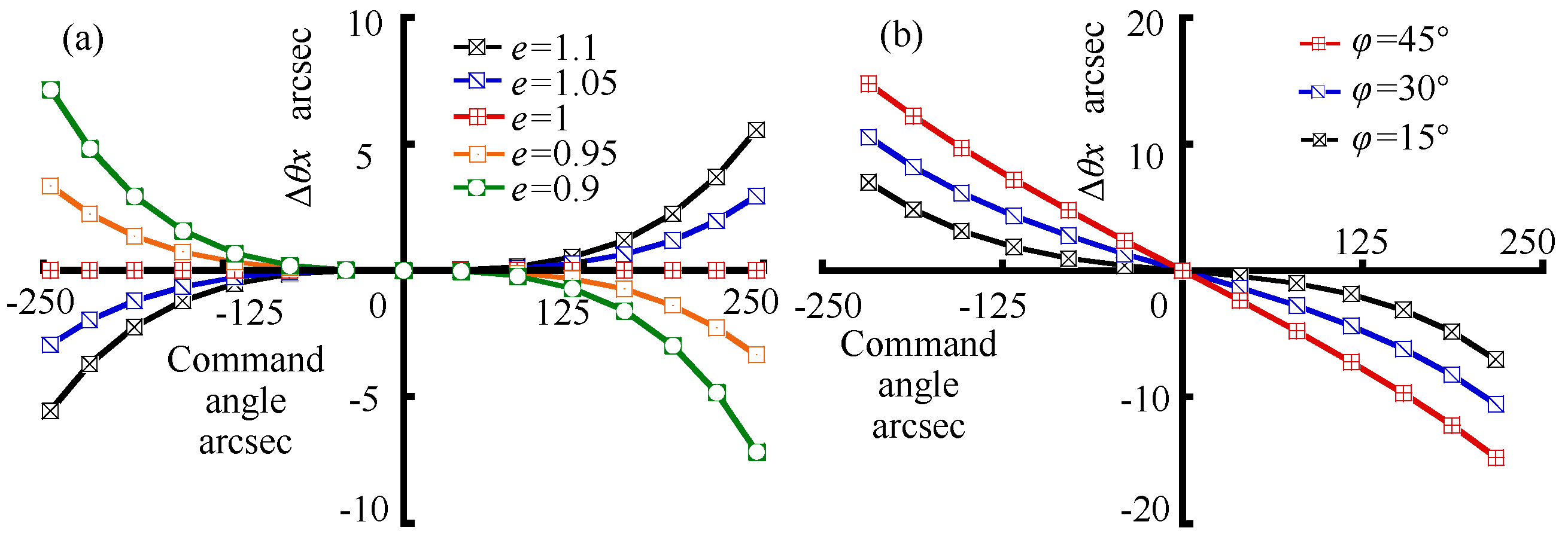
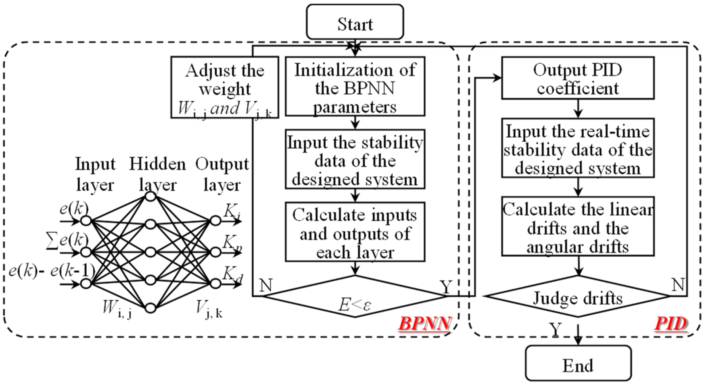
3.3. Effect of the Stability in Output Beam Direction of the LD

Laser beam drifts have been proved to be one of the critical error sources in the LD-based measurement system, especially for the long-distance measurement. In our previous works [11], an active error compensator, which consisted of an optical mount (OM), a mirror and two mini-sized PZT actuators was proposed to compensate the angular drift of the LD. However, it only considered the angular drift near the sensor head. The laser beam drifted far away from the sensor head and the linear drift was not considered.
To address the above problems, an improved active error compensator (IAEC) was proposed and integrated into the LD-based system for simultaneously compensating the linear drift and the angular drift of the LD in the long-distance measurement. The principle of the IAEC is shown in Figure 6, which was composed of a feedback unit 1, a feedback unit 2 and a Backpropagation Neural Networks-based PID (BPNN-based PID) controller. The feedback unit 1 consisted of QD5 and a mechanism 1. The feedback unit 2 consisted of QD6, FL6 and a mechanism 2. The mechanism 1 and the mechanism 2 had an identical construction, which consisted of an optical mount (OM), a mirror (M) and two mini-sized PZT actuators (P). Compared with previous research [11,23,24], the improved active error compensator was not only simple in structure, but could also compensate both the linear drift and the angular drift of the laser source for the long-distance measurement.
The inputs of the BPNN and the PID controller were the outputs of QD5 (δα and δβ) and QD6 (θα and θβ), which represented the linear drift and the angular drift of the LD-based system. The parameters of the PID controller (Ki, Kp, Kd) were obtained in real-time by the neural network training of the BPNN. The angles of OM1 and OM2 were fast tuned by controlling the mini-PZTs’ voltages (Vi, i = 1 to 4) using the BPNN PID controller. M1 and M2, mounted on OM1 and OM2, were then employed to adjust the propagation direction of the laser beams so that the laser spots could always remain at the centers of QD5 and QD6, from which the linear drift and the angular drift of the LD could be actively compensated.
The outputs of QD5 (δα and δβ) and QD6 (θα and θβ) were, respectively, composed of four parts, namely outputs caused by the angular drift (α0 and β0), outputs caused by the linear drift (ε and η), outputs caused by the rotation of M1 (α1 and β1) and outputs caused by the rotation of M2 (α2 and β2), as shown in Figure 7. For the sake of being brief, only the related optical elements and the intersection point between the optical element and the laser beam are shown in Figure 7.
In the ideal case, the incident laser beam I0 travels along the Z-axis with a direction vector of [ 0 0 1 ] T . However, the direction vector is varied to be [ α 0 β 0 1 ] T when the angular drift (α0 and β0) exists about the X and Y axes, as shown in Figure 7a. The normal vector of the reflection planes of M1, M2 and BS1 can be expressed by:
n M 1 = [ N M 1 x N M 1 y N M 1 z ]   =   [ 2 2 0 2 2 ] T ,
n M 2 = [ N M 2 x N M 2 y N M 2 z ]   =   [ 2 2 0 2 2 ] T ,
n B S = [ N B S x N B S y N B S z ]   =   [ 2 2 0 2 2 ] T ,
The direction vectors of the laser beams (I1′, I2′ and I3′) reflected from M1, M2 and BS1 can thus be expressed as:
I 1 = M M 1 I 0 = [ 1 2 N M 1 x 2 2 N M 1 x N M 1 y 2 N M 1 x N M 1 z 2 N M 1 x N M 1 y 1 2 N M 1 y 2 2 N M 1 y N M 1 z 2 N M 1 x N M 1 z 2 N M 1 y N M 1 z 1 2 N M 1 z 2 ] [ α 0 β 0 1 ] = [ 1 α 0 β 0 ] ,
I 2 = M M 2 I 1 = [ 1 2 N M 2 x 2 2 N M 2 x N M 2 y 2 N M 2 x N M 2 z 2 N M 2 x N M 2 y 1 2 N M 2 y 2 2 N M 2 y N M 2 z 2 N M 2 x N M 2 z 2 N M 2 y N M 2 z 1 2 N M 2 z 2 ] [ 1 α 0 β 0 ] = [ α 0 β 0 1 ]   ,
I 3 = M M BS I 2 = [ 1 2 N B S x 2 2 N B S x N B S y 2 N B S x N B S z 2 N B S x N B S y 1 2 N B S y 2 2 N B S y N B S z 2 N B S x N B S z 2 N B S y N B S z 1 2 N B S z 2 ] [ α 0 β 0 1 ] = [ 1 α 0 β 0 ] ,
Therefore, the X- and Y-directional outputs of QD6 caused by the angular drift (α0 and β0) can be evaluated to be α0 and −β0 according to Equation (15).
The coordinates of the emitting point O of I0 from the LD and the intersection point A between I0 and M1 were set to be (0, 0, 0) and (0, 0, −d1), respectively. d1 represents the distance between the LD and M1. The line function of the emitted laser beam I1′ and the plane equation of M1 can thus be expressed as:
x α 0 = y β 0 = z   and   2 2 x + 2 2 ( z + d 1 ) = 0 ,
Therefore, the coordinate of the intersection point A′ between I0′ and M1 can be evaluated to be: ( A x ,   A y ,   A z ) = ( d 1 α 0 1 α 0 ,   d 1 β 0 1 β 0 ,   d 1 1 α 0   ) .
Similarly, the coordinate of the point D′, which is the intersection point between QD5 and I3′, can be calculated to be: ( D x ,   D y ,   D z   ) = ( d 2 + d 4 ,   d 1 + d 2 + d 3 + d 4 ( 1 + α 0 ) ( 1 α 0 2 ) β 0 ,   d 3 d 1 + ( 2 d 3 d 4 d 2 ) α 0 ( 1 + α 0 ) ( 1 α 0 2 ) ) . Therefore, the X- and Y-directional outputs of QD5 caused by the angular drift (α0 and β0) are evaluated to be: ( d 1 d 2 + d 3 d 4 1 + α 0 α 0 ,   d 1 + d 2 + d 3 + d 4 1 + α 0 β 0 ) . Here, d2, d3 and d4 represent the distance between M1 and M2, M2 and BS1 and BS1 and QD5, respectively.
Similarly, the outputs of QD5 (δα and δβ) and QD6 (θα and θβ) caused by the linear drift (ε and η), the rotation of M1 (α1 and β1) and the rotation of M2 (α2 and β2) can be calculated. Therefore, the total outputs of QD5 (δα and δβ) and QD6 (θα and θβ) can be expressed by:
{ [ δ α δ β ] = [ d 1 d 2 + d 3 d 4 1 + α 0 α 0 ε + m 1 2 α 1 ( 2 d 4 + 2 d 3 + 2 d 2 m 1 + m 2 2 ) β 1 1 + 3 β 1 + n 1 2 α 2 + ( 2 d 4 + 2 d 3 + n 1 + n 2 2 ) β 2 1 3 β 2 d 1 + d 2 + d 3 + d 4 1 + α 0 β 0 + η + ( d 2 + d 3 + d 4 ) α 1 1 + 3 β 1 + ( d 3 + d 4 ) α 2 1 β 2 ] [ θ α θ β ] = [ α 0 2 β 1 2 β 2 β 0 α 1 α 2 ] ,
where m1 and m2 represent the distance between P1 and P2, and the length of M1. n1 and n2 represent the distance between P3 and P4, and the length of M2.
As a result, the proposed IAEC, compensating both the linear drift and the angular drift, is a complex coupled nonlinear system. In addition, the proposed LD-based system was constructed for measuring the geometric errors of machine tools, which are usually located in a non-environmentally controlled open factory. In this case, if a traditional PID controller was used in the LD-based system, it would be difficult to actively compensate the laser beam drifts over a long period of time, and the parameters of the PID controller would need to be adjusted after a period of time, which would affect the efficiency, the accuracy and the reproducibility of the geometric errors measurement. Therefore, a BPNN-based PID controller was used in this research to quickly and accurately adjust the angles of M1 and M2 to simultaneously compensate the linear and the angular drifts.
The flowchart of the BPNN-based PID controller is shown in Figure 8. A neural network, consisting of the input layer with three neurons, the hidden layer with five neurons and the output layer with three neurons, was used. The three neurons of the output layer represented the PID controller parameters Ki, Kp and Kd, which needed to be trained by the BPNN according to the stability data of the designed system. It was essential to adjust the BPNN parameters during the training to let e(k) reach the minimum performance index ε, at which the neural network training was finished. The obtained PID controller parameters were used to control the driven voltage of the mini-PZTs according to the instantaneously measured linear and angular drifts in real-time. The mini-PZTs changed the angles of M1 and M2 with opposite directions of the detected linear and angular drifts so that the linear and angular drifts could be compensated.

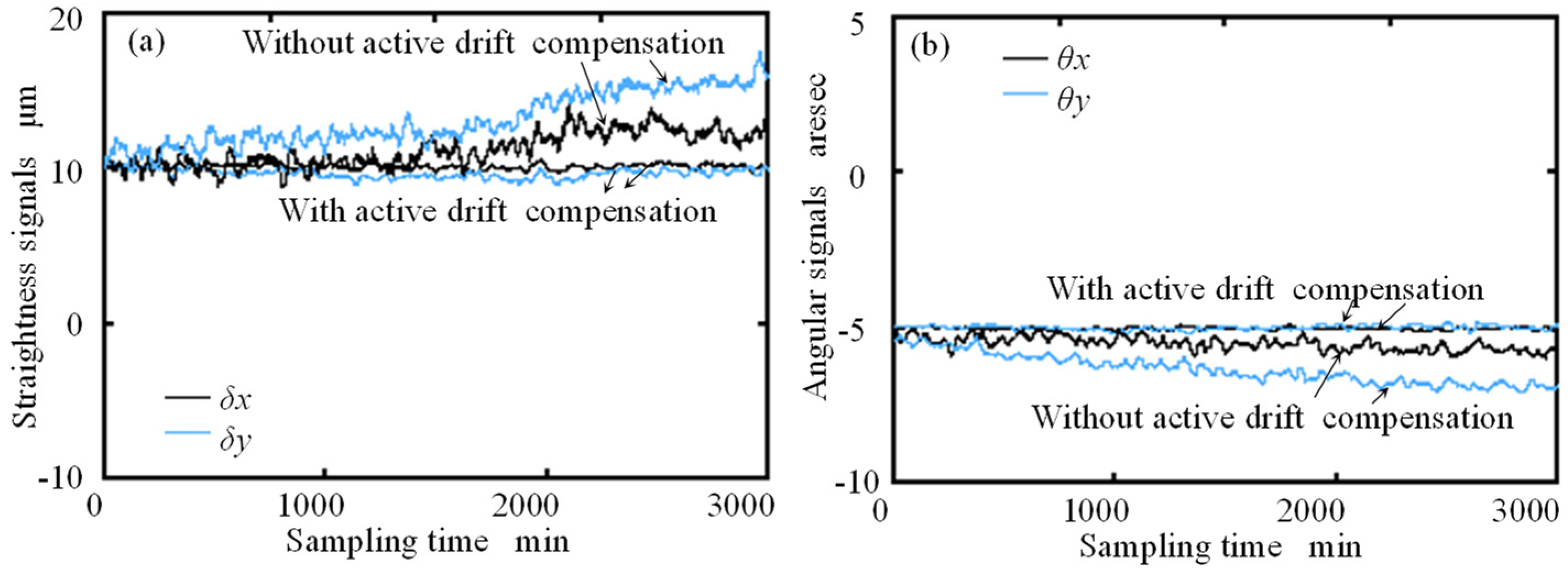
4. Experiment and Discussion

A series of experiments were carried out to verify the effectiveness of the above-motioned active methods. A laboratory-built prototype of the LD-based system was constructed to measure the δx, δy, θx and θy of a linear stage, as shown in Figure 9. A compact and low-cost LD (DA635, Huanic, Xi’an, China), which had an X-directional diameter dx of 5 mm, an ellipticity e of 0.945 and a wavelength of 635 nm, was adopted as the laser source of the system. A comparison unit, with a construction similar to the detector, was integrated into the measurement system to carry out a group of comparison experiments. The s1, s2 and s3 shown in Figure 9 represent the distance between the sensor head and the feedback unit 2, and the detector and the comparison unit, respectively.
Firstly, the effect of the position offset Δz on the laser spot characteristic was investigated. The relationship between the sensitivity of the photodetector and the diameter of the laser beam can be expressed by:
K θ x ( Δ z ) = 8 1.22 π d x Δ z λ   and   K θ y ( Δ z ) = 8 1.22 π d y Δ z λ ,
where Kθxz) and Kθyz) represent the X- and Y-directional sensitivities of the QD, respectively. As can be seen, if Kθxz) equals Kθyz), dxΔz will be equal to dyΔz, which means the elliptical laser spot is shaped to be a circle laser spot. Therefore, Δz can be confirmed by the evaluated Kθxz) and Kθyz) using a group of calibration experiments.
Figure 10 shows the calibrated X-directional and Y-directional sensitivities of the QD under various Δz. As can be seen, when Δz equals 48.73 μm, Kθxz) is approximately equal to Kθyz). As mentioned above, the LD exits at a divergence angle α, which will affect Δz. Therefore, a commercial beam-profiling camera was used to detect the diameter of the LD at various measurement positions. When s2 was set to be 50 mm and 1500 mm, the X-directional diameter (dx) of the LD was evaluated to be 5.0 mm and 5.4 mm, respectively. The variation of Δz was thus evaluated to be 4.51 μm according to the simulation results. The variation of Δz was small enough that the effect of the divergence angle of the LD along the measurement direction on the measurement accuracy of the geometric errors could be ignored. Therefore, the position offset Δz was fixed to be 48.73 μm in the following experiments.
The capability of the designed IAEC and the stability of the LD-based measurement system were then tested. Firstly, the traditional PID controller was used to compensate the laser beam drifts for comparison. Figure 11 shows the outputs of QD5 and QD6 when the IAEC was activated with the traditional PID controller. s1, the sampling time and the sampling frequency were set to be 1800 mm, 5 h and 100 Hz, respectively. The Butterworth filter and the moving average method were applied to reduce the effect of the noise. It can be seen from the figure that the stability ranges of QD5 and QD6 were within 2.0 μm and 5.0 arcsec, respectively.
The BPNN-based PID controller was then used to compensate the laser beam drifts. A neural network with three, five and three neurons in the input layer, the hidden layer and the output layer, respectively, was applied. A tangent hyperbolic was selected as an activation function of the hidden layer and the output layer of the BPNN-based PID controller. The momentum factor and the learning rate, which affect the stability and speed of the training process of the BPNN, were set to be 0.2 and 0.01, respectively. The number of the training sample in the BPNN was 183,180 and the minimum performance index ε was set to 0.0001.
Figure 12 shows the outputs of QD5 and QD6 when the IAEC was activated with the BPNN-based PID controller. As can be seen, the outputs of QD5 and QD6 remained near zero during 5 h. It can be verified that M1 and M2 can be rotated by four mini-PZTs to the opposite direction of the detected linear and angular drifts so as to keep the laser spots at the centers of QD5 and QD6, respectively. Comparing with results shown in Figure 11 and Figure 12, it can be seen that the traditional PID controller was not suitable for the proposed improved active error compensator. Therefore, the BPNN-based PID controller rather than the traditional PID controller was used to compensate the laser beam drifts for the long-distance measurement over a long period of time.
Figure 13 shows the stability tests of the straightness signals (δx and δy) and the angular signals (θx and θy), which were simultaneously measured by the detector and the comparison unit when s2 and s3 were set to be 50 mm, respectively. It can be seen from Figure 13a that the standard deviations of δx and δy with the active drift compensation were evaluated to be 0.11 μm and 0.13 μm, respectively. However, the standard deviations of δx and δy without the active drift compensation were evaluated to be 0.44 μm and 0.95 μm, respectively. The standard deviation of θx with and without the active drift compensation was estimated to be 0.08 arcsec and 0.55 arcsec, respectively, and the standard deviation of θy with and without the active drift compensation was evaluated to be 0.09 arcsec and 0.90 arcsec, respectively, as shown in Figure 13b.
The stabilities of δx, δy, θx and θy when s2 were set to be 500 mm and 1500 mm were also tested. For the sake of clarity, the stability resulted when s2 was set to be 50 mm, 500 mm and 1500 mm, as summarized in Table 1. As can be seen, the signals with the active drift compensation were better stabilized than those without the active drift compensation. Although the stabilities of δx, δy, θx and θy at the position of 1500 mm were poorer than those at the position of 50 mm and 500 mm, the stabilities of δx, δy, θx and θy could always be controlled within ±1 μm and ±0.3 arcsec, respectively, from which the effectiveness of the IAEC was demonstrated.
Finally, the laboratory-built LD-based measurement system was used to measure the straightness and the angular errors of a linear stage with a travel stroke of 1.5 m. The proposed active methods were used to improve the measurement accuracy of the designed system. Standard instruments, including a commercial laser interferometer and a commercial autocollimator, were also used to simultaneously measure the straightness and the angular errors of the stage to calibrate the measurement accuracy of the LD-based measurement system. The measured results are shown in Figure 14. The left vertical axis of the figure is the δx, δy, θx and θy measured simultaneously by using the standard instruments and the proposed LD-based system. The right vertical axis of the figure, which is the difference between the results measured by using the standard instruments and the proposed LD-based system, represents the measurement accuracy of the designed LD-based system. The horizontal axis is the measurement distance. As can be seen, the measurement accuracy of the straightness errors and the angular errors of the designed LD-based system were evaluated to be within ±1.1 μm and ±2.0 arcsec, respectively, in the measurement distance up to 1.5 m.

5. Conclusions

A compact 4-DOF LD-based system was designed for measuring the straightness errors and the angular errors of machine tools. In order to reduce the size of the measurement system and realize the on-line measurement, a laser diode (LD) was adopted as the laser source of the measurement system. An active method for shaping the laser spot of the LD without adding additional optical elements is proposed to reduce the measurement error caused by the elliptical laser spot of the LD. In addition, the measurement errors induced by the linear drift and the angular drift of the LD were actively compensated by an improved active error compensator. The stabilities of the horizontal and vertical straightness signals were, respectively, improved from 2.91 μm and 4.67 μm to 0.88 μm and 1.02 μm, and the stabilities of the pitch and yaw signals were, respectively, improved from 1.35 arcsec and 1.92 arcsec to 0.11 arcsec and 0.17 arcsec when the distance between the sensor head and the detector was set to be 1500 mm. The measurement accuracy of the straightness errors and the angular errors were evaluated to be within ±1.1 μm and ±2.0 arcsec, respectively, in the measurement distance up to 1500 mm. Therefore, the effectiveness of the proposed methods and the capability of the constructed LD-based measurement system were verified. The analyses of the uncertainty and systematic error will be carried out in the future work.

Author Contributions

Conceptualization, Y.C. and K.F.; methodology, Y.C. and K.F.; software, K.Y. and Q.F.; validation, Y.C., Y.G. and K.Y.; formal analysis, Y.C., Y.G. and K.Y.; investigation, Y.G. and K.Y.; resources, Y.G., Y.C. and K.F.; data curation, Q.F. and K.Y.; writing—original draft preparation, Y.C.; writing—review and editing, K.F.; visualization, Y.C. and K.F.; supervision, Y.C. and K.F.; project administration, Y.C. and K.F.; funding acquisition, Y.C. All authors have read and agreed to the published version of the manuscript.

Funding

This work was supported by the National Natural Science Foundation of China (51905078), the National Key Research and Development Program of China (2018YFB2001400) and Fundamental Research Funds for the Central Universities (DUT19RC(4)007).

Institutional Review Board Statement

Not applicable.

Informed Consent Statement

Not applicable.

Data Availability Statement

The data presented in this research are available on request from the corresponding author.

Acknowledgments

The authors thank Binhe Yang for his help in the preparation of the experimental setup.

Conflicts of Interest

The authors declare no conflict of interest.

References

  1. Zhao, D.; Bi, Y.; Ke, Y. An efficient error compensation method for coordinated CNC five-axis machine tools. Int. J. Mach. Tools Manuf. 2017, 123, 105–115. [Google Scholar] [CrossRef]
  2. Schwenke, H.; Knapp, W.; Haitjema, H.; Weckenmann, A.; Schmitt, R.; Delbressine, F. Geometric error measurement and com-pensation of machines-an update. CIRP Ann. 2008, 57, 660–675. [Google Scholar] [CrossRef]
  3. Ramesh, R.; Mannan, M.A.; Poo, A.N. Error compensation in machine tools—A review: Part I: Geometric, cutting-force induced and fixture-dependent errors. Int. J. Mach. Tools Manuf. 2000, 40, 1235–1256. [Google Scholar] [CrossRef]
  4. Kwasny, W.; Turek, P.; Jedrzejewski, J. Survey of machine tool error measuring methods. J. Mach. 2011, 11, 7–38. [Google Scholar]
  5. Archenti, A.; Nicolescu, M.; Casterman, G.; Hjelm, S. A new method for circular testing of machine tools under loaded con-dition. Procedia CIRP 2012, 1, 575–580. [Google Scholar] [CrossRef]
  6. Wang, J.; Guo, J. The identification method of the relative position relationship between the rotary and linear axis of multi-axis numerical control machine tool by laser tracker. Measurement 2019, 132, 369–376. [Google Scholar] [CrossRef] [Green Version]
  7. Chen, J.R.; Ho, B.L.; Lee, H.W.; Pan, S.P.; Hsieh, T.H. Research on geometric errors measurement of machine tools using auto-tracking laser interferometer. J. Eng. Technol. 2018, 6, 631–636. [Google Scholar] [CrossRef] [Green Version]
  8. ISO230-1 2012; Test Code for Machine Tools-Part 1: Geometric Accuracy of Machines Operating under No-Load or Quasi-Static Conditions. ISO: Geneva, Switzerland, 2012.
  9. Anke, G.; Dirk, S.; Gert, G. Self-calibration method for a ball plate artefact on a CMM. CIRP Ann. 2016, 65, 503–506. [Google Scholar]
  10. Cai, Y.; Wang, L.; Liu, Y.; Li, Y.; Fan, K.C. Accuracy improvement of linear stages using on-machine geometric error measurement system and error transformation model. Opt. Express 2022, 30, 7539–7550. [Google Scholar] [CrossRef]
  11. Cai, Y.; Yang, B.; Fan, K.C. Robust roll angular error measurement system for precision machines. Opt. Express 2019, 27, 8027. [Google Scholar] [CrossRef]
  12. Cai, Y.; Xie, B.; Wen, Z.; Fan, K.C. A miniature laser diode interferometer with self-compensation of retroreflector’s motion errors for displacement feedback of small-sized micro/nano motion stages. Measurement 2021, 186, 110172. [Google Scholar] [CrossRef]
  13. Ni, J.; Wu, S.M. An On-line measurement technique for machine volumetric error compensation. J. Eng. Ind-Trans. ASME 1993, 115, 85–92. [Google Scholar] [CrossRef]
  14. Jia, P.; Zhang, B.; Feng, Q.; Zheng, F. Simultaneous measurement of 6DOF motion errors of linear guides of CNC machine tools using different modes. Sensors 2020, 20, 3439. [Google Scholar] [CrossRef] [PubMed]
  15. Cui, S.; Soh, Y.C. Analysis and improvement of Laguerre Gaussian beam position estimation using quadrant detectors. Opt. Lett. 2011, 36, 1692–1694. [Google Scholar] [CrossRef]
  16. Jing, X.; Cheng, H.; Xu, C.; Feng, Y. Method to measure the position offset of multiple light spots in a distributed aperture laser angle measurement system. Appl. Opt. 2017, 56, 1740–1747. [Google Scholar] [CrossRef] [PubMed]
  17. Zhou, X.; Bryan, N.K.A.; Koh, S.S. Single aspherical lens for deastigmatism, collimation, and circularization of a laser beam. Appl. Opt. 2000, 39, 1148–1151. [Google Scholar] [PubMed]
  18. Serkan, M.; Kirkici, H. Optical beam-shaping design based on aspherical lens for circularization, collimation, and expansion of elliptical laser beam. Appl. Opt. 2008, 47, 230–241. [Google Scholar] [CrossRef] [PubMed]
  19. Tian, Z.; Nix, M.; Yam, S. Laser beam shaping using a single-mode fiber abrupt taper. Opt. Lett. 2009, 34, 229–231. [Google Scholar] [CrossRef] [Green Version]
  20. Kuang, C.; Hong, E.; Feng, Q. High-accuracy method for measuring two-dimensional angles of a linear guideway. Opt. Eng. 2007, 46, 51016. [Google Scholar]
  21. Li, K.; Kuang, C.; Liu, X. Small angular displacement measurement based on an autocollimator and a common-path compensation principle. Rev. Sci. Instrum. 2013, 84, 15108. [Google Scholar] [CrossRef]
  22. Hu, P.; Mao, S.; Tan, J. Compensation of errors due to incident beam drift in a 3 DOF measurement system for linear guide motion. Opt. Express 2015, 23, 28389. [Google Scholar] [CrossRef] [PubMed]
  23. Zhao, W.; Tan, J.; Qiu, L.; Zou, L.; Cui, J.; Shi, Z. Enhancing laser beam directional stability by single-mode optical fiber and feedback control of drifts. Rev. Sci. Instrum. 2005, 76, 036101–03601-3. [Google Scholar] [CrossRef]
  24. Zhao, W.; Qiu, L.; Feng, Z.; Li, C. Laser beam alignment by fast feedback control of both linear and angular drifts. Optik 2006, 117, 505–510. [Google Scholar] [CrossRef]
Figure 1. Schematic of the LD-based system.
Applsci 12 03479 g001
Figure 2. Effect of rx on (a) Δδx and (b) Δθx.
Applsci 12 03479 g002
Figure 3. Effects of (a) e and (b) φ on Δθx.
Applsci 12 03479 g003
Figure 4. Relationship between the position offset and the laser beam diameter.
Applsci 12 03479 g004
Figure 5. Effect of the position offset on the measurement accuracy (a) without the angular error, (b) with the angular error and (c) with the straightness error.
Applsci 12 03479 g005
Figure 6. Principle of the IAEC.
Applsci 12 03479 g006
Figure 7. Outputs of QD5 and QD6 caused by (a) the angular drift, (b) the linear drift, (c) the rotation of M1 and (d) the rotation of M2.
Applsci 12 03479 g007
Figure 8. The flowchart of the BPNN-based PID controller.
Applsci 12 03479 g008
Figure 9. Experimental setup of the LD-based measurement system with the IAEC.
Applsci 12 03479 g009
Figure 10. Relationship between Δz and the detector sensitivity.
Applsci 12 03479 g010
Figure 11. Outputs of (a) QD5 and (b) QD6 when the IAEC was activated with the traditional PID controller.
Applsci 12 03479 g011
Figure 12. Outputs of (a) QD5 and (b) QD6 when the IAEC was activated with the BPNN-based PID controller.
Applsci 12 03479 g012
Figure 13. Stability tests of (a) the straightness signals and (b) the angular signals measured by the detector and the comparison unit when s2 = s3 = 50 mm.
Applsci 12 03479 g013
Figure 14. Measured results of (a) δx, (b) δy, (c) θx and (d) θy measured three times.
Applsci 12 03479 g014
Table 1. Stability tests of the signals with and without the active drift compensation at the positions of 50 mm, 500 mm and 1500 mm.
With Active Drift CompensationWithout Active Drift Compensation
50 mm500 mm1500 mm50 mm500 mm1500 mm
δx [μm]0.110.710.880.441.822.91
δy [μm]0.130.761.020.952.514.67
θx [arcsec]0.080.060.110.551.161.35
θy [arcsec]0.090.110.170.900.931.92
Publisher’s Note: MDPI stays neutral with regard to jurisdictional claims in published maps and institutional affiliations.

