
Overview of Power Electronic Converter Topologies Enabling Large-Scale Hydrogen Production via Water Electrolysis


Abstract
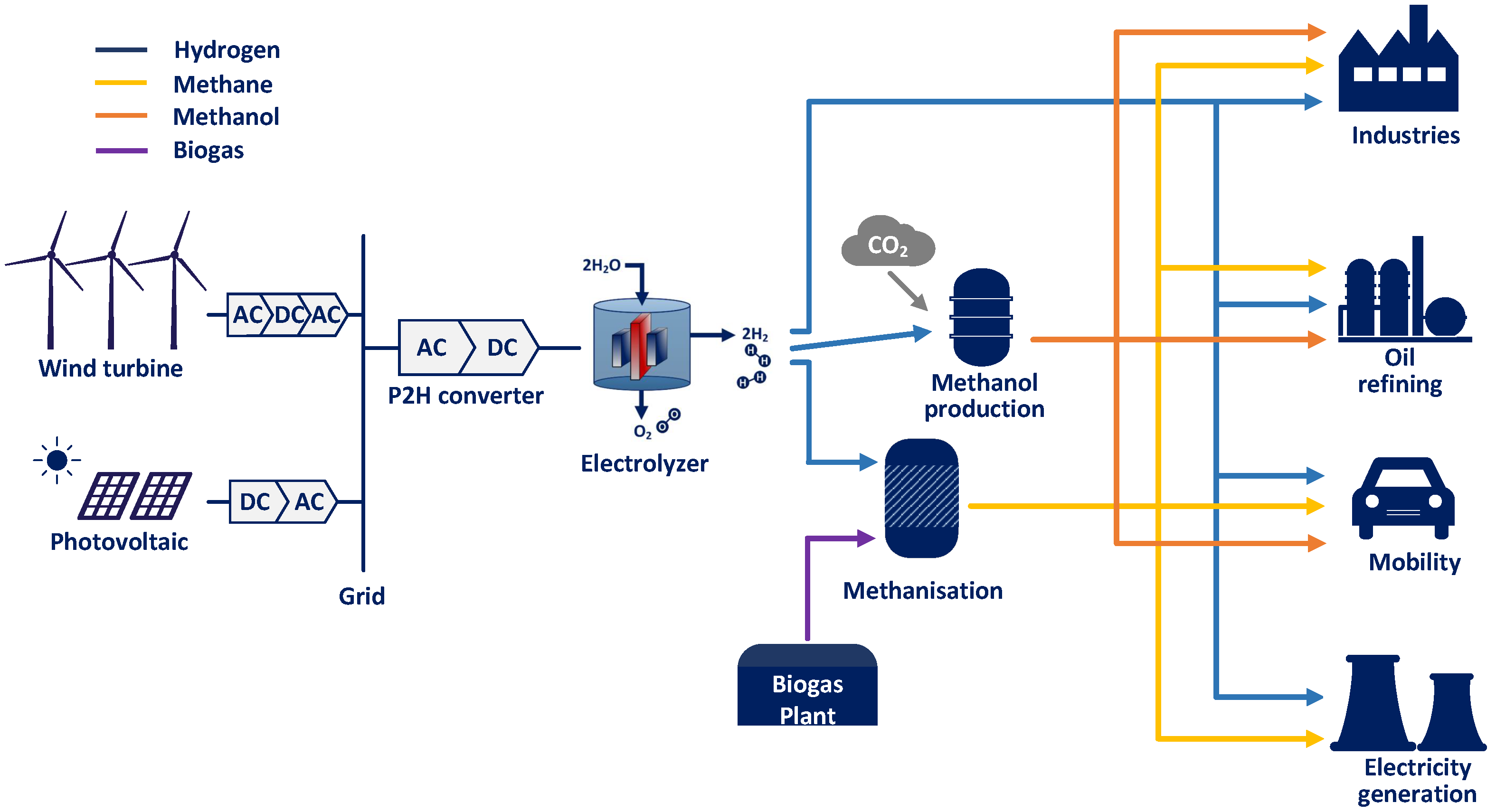
:1. Introduction
2. General Requirements
2.1. Load Specifications
2.2. Grid Requirements
3. State-of-the-Art Solutions
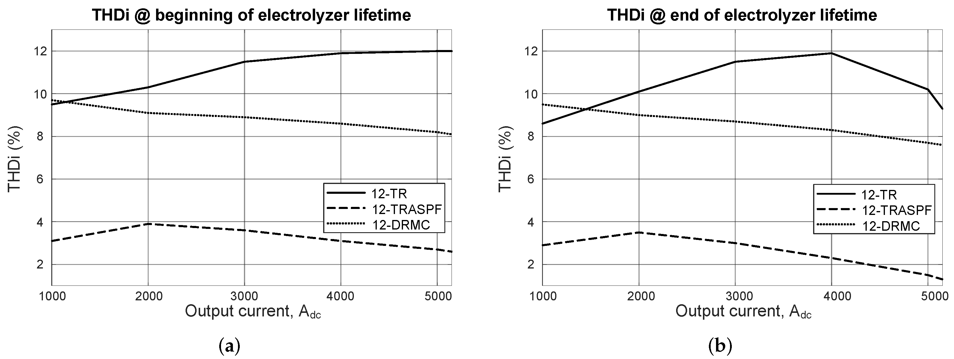
3.1. 12-Pulse Thyristor Rectifier (12-TR)
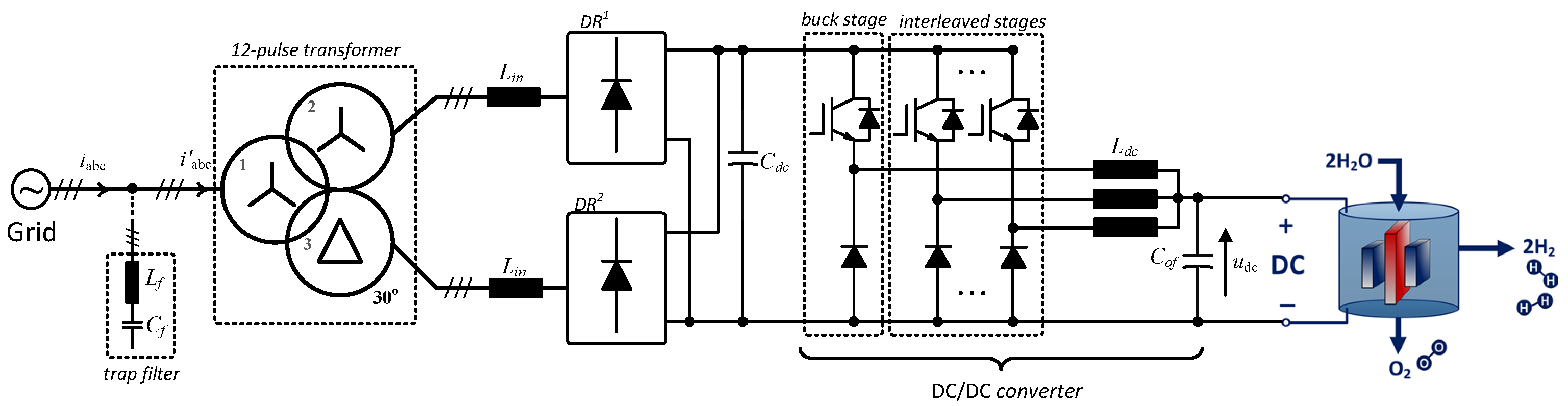
3.2. 12-Pulse Diode Rectifier with Multi-Phase Chopper (12-DRMC)
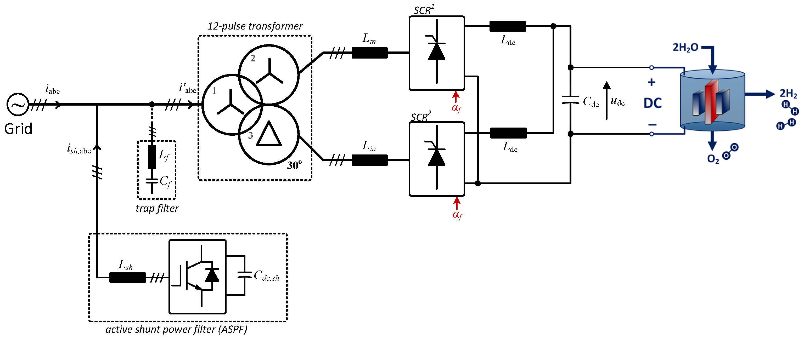
3.3. 12-Pulse Thyristor Rectifier with Active Shunt Power Filter (12-TRASPF)
3.4. Active Front End (AFE) Rectifier
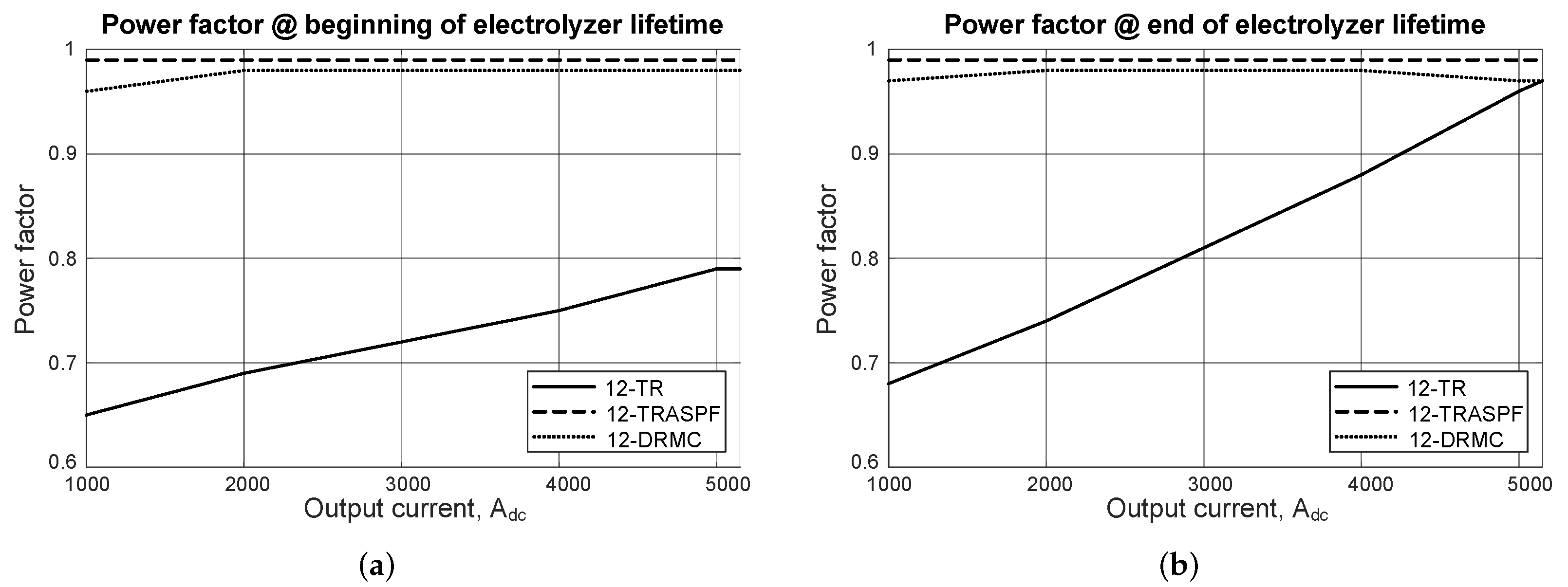
4. Performance Comparison
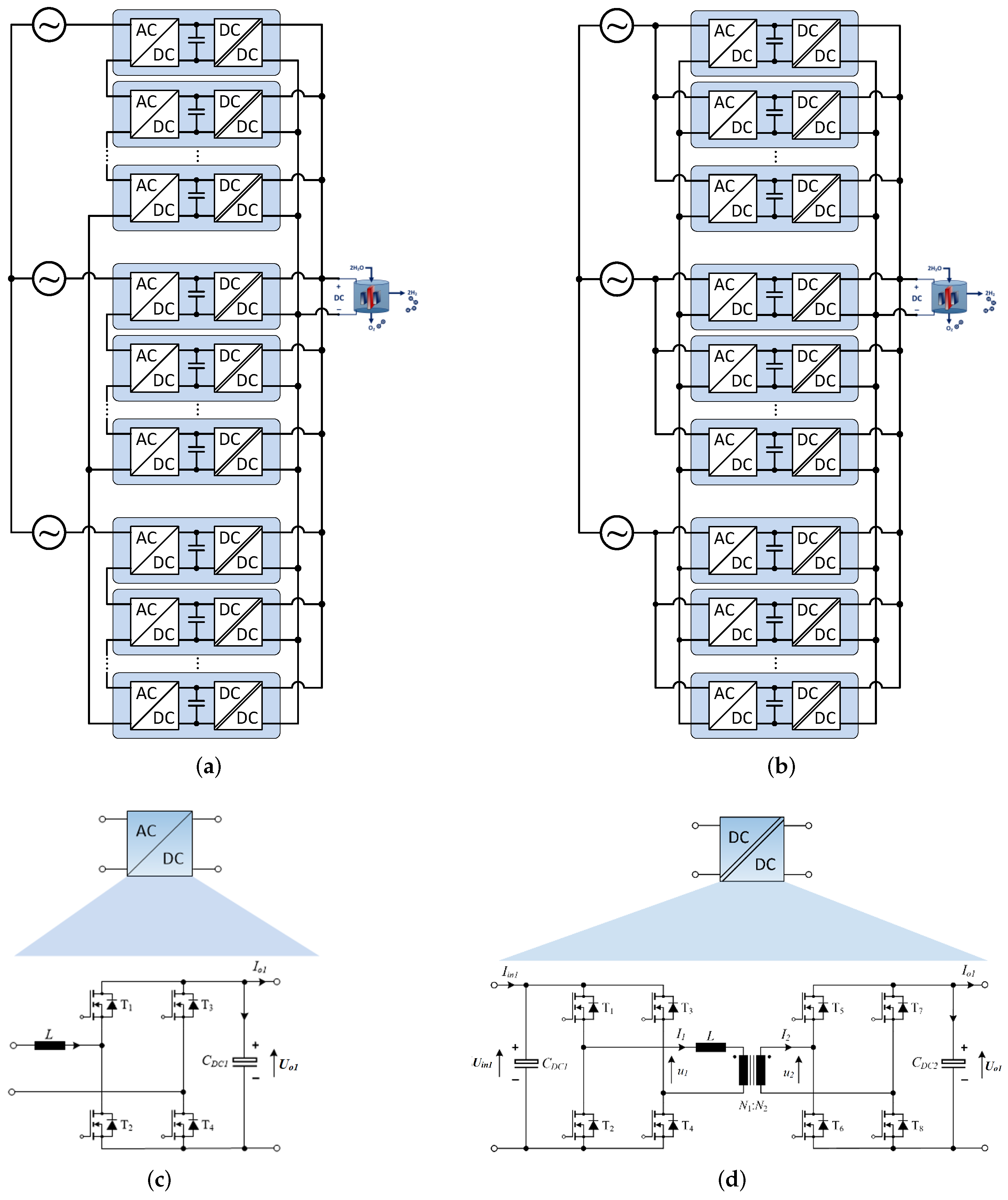
5. Future Trends and Opportunities—Modular Multicell Rectifier
6. Conclusions
Author Contributions
Funding
Institutional Review Board Statement
Informed Consent Statement
Data Availability Statement
Conflicts of Interest
References
- The Future of Hydrogen, Technology Report, IEA. June 2019. Available online: https://www.iea.org/reports/the-future-of-hydrogen (accessed on 4 December 2021).
- Making Mission Possible: Delivering a Net Zero Economy, Technology Report, Energy Transitions Commission. September 2020. Available online: https://www.energy-transitions.org/publications/making-mission-possible/ (accessed on 4 December 2021).
- Ursua, A.; Gandia, L.M.; Sanchis, P. Hydrogen production from water electrolysis: Current status and future trends. Proc. IEEE 2012, 100, 410–426. [Google Scholar] [CrossRef]
- The “Renewable Molecule”: The Potential of Hydrogen from Renewable Energy, White Paper, Orsted. Available online: https://orsted.com/en/about-us/whitepapers/decarbonising-society-with-power-to-x/power-to-x (accessed on 30 December 2021).
- A Hydrogen Strategy for a Climate-Neutral Europe; White Paper; European Commission: Brussels, Belgium, 2020.
- Blaabjerg, F.; Teodorescu, R.; Liserre, M.; Timbus, A.V. Overview of Control and Grid Synchronization for Distributed Power Generation Systems. IEEE Trans. Ind. Electron. 2006, 53, 1398–1409. [Google Scholar] [CrossRef] [Green Version]
- Koutroulis, E.; Kalaitzakis, K. Design of a maximum power tracking system for wind-energy-conversion applications. IEEE Trans. Ind. Electron. 2006, 53, 486–494. [Google Scholar] [CrossRef]
- Santos, D.M.F.; Sequeira, C.A.C.; Figueiredo, J.L. Hydrogen production by alkaline water electrolysis. Química Nova 2013, 36, 1176–1193. [Google Scholar] [CrossRef]
- Carmo, M.; Fritz, D.L.; Mergel, J.; Stolten, D. A comprehensive review on PEM water electrolysis. Int. J. Hydrogen Energy 2013, 38, 4901–4934. [Google Scholar] [CrossRef]
- Wind Resource: Utilising Hydrogen Buffering–Electrolyser. Available online: http://www.esru.strath.ac.uk/EandE/Web_sites/08-09/Hydrogen_Buffering/Website%20Electrolyser.html (accessed on 11 October 2021).
- Shell Starts up Hydrogen Electrolyser in China with 20 MW Production Capacity, Shell Plc. Available online: https://www.shell.com/media/news-and-media-releases/2022/shell-starts-up-hydrogen-electrolyser-in-china-with-20mw-product.html (accessed on 30 December 2021).
- From Wind Power to Green Hydrogen. Available online: https://hybalance.eu/ (accessed on 30 December 2021).
- Linde Engineering to Build 24 MW PEM Electrolyzer Plant for Yara, Linde Plc. Available online: https://www.linde-engineering.com/en/news_and_media/press_releases/news20220128.html (accessed on 30 December 2021).
- Blaabjerg, F. Ten Breakthrough Ideas in Energy for the Next Ten Years: Power to E-Fuel; Global Energy: Moscow, Russia, 2021. [Google Scholar]
- Siebert, A.; Troedson, A.; Ebner, S. AC to DC power conversion now and in the future. IEEE Trans. Ind. Appl. 2002, 38, 934–940. [Google Scholar] [CrossRef]
- Solanki, J.; Fröhleke, N.; Böcker, J. Implementation of hybrid filter for 12-pulse thyristor rectifier supplying high-current variable-voltage DC load. IEEE Trans. Ind. Electron. 2015, 62, 4691–4701. [Google Scholar] [CrossRef]
- Aqueveque, P.E.; Wiechmann, E.P.; Burgos, R.P. On the efficiency and reliability of high-current rectifiers. In Proceedings of the 2008 IEEE Power Electronics Specialists Conference, Rhodes, Greece, 15–19 June 2008. [Google Scholar] [CrossRef]
- Solanki, J.; Fröhleke, N.; Böcker, J.; Wallmeier, P. Analysis, design and control of 1MW, high power factor and high current rectifier system. In Proceedings of the 2012 IEEE Energy Conversion Congress and Exposition (ECCE), Raleigh, NC, USA, 15–20 September 2012. [Google Scholar] [CrossRef]
- Mohamadian, S.; Ghandehari, R.; Shoulaie, A. A comparative study of AC/DC converters used in high current applications. In Proceedings of the 2011 2nd Power Electronics, Drive Systems and Technologies Conference, Tehran, Iran, 16–17 February 2011. [Google Scholar] [CrossRef]
- Rodriguez, J.R.; Pontt, J.; Silva, C.; Wiechmann, E.P.; Hammond, P.W.; Santucci, F.W.; Alvarez, R.; Musalem, R.; Kouro, S.; Lezana, P. Large current rectifiers: State of the art and future trends. IEEE Trans. Ind. Electron. 2005, 52, 738–746. [Google Scholar] [CrossRef]
- Solanki, J.; Fröhleke, N.; Böcker, J.; Averberg, A.; Wallmeier, P. High-current variable-voltage rectifiers: State of the art topologies. IET Power Electron. 2015, 8, 1068–1080. [Google Scholar] [CrossRef]
- PowerKraftTM Power Supply Solution for Hydrogen Production, KraftPowercon. Available online: https://kraftpowercon.com/product/powerkraft (accessed on 30 December 2021).
- Maniscalco, P.S.; Scaini, V.; Veerkamp, W.E. Specifying DC chopper systems for electrochemical applications. IEEE Trans. Ind. Appl. 2001, 37, 941–948. [Google Scholar] [CrossRef]
- Scaini, V.; Ma, T. High-current DC choppers in the metals industry. IEEE Ind. Appl. Mag. 2002, 8, 26–33. [Google Scholar] [CrossRef]
- Suh, Y.; Steimer, P.K. Application of IGCT in high-power rectifiers. IEEE Trans. Ind. Appl. 2009, 45, 1628–1636. [Google Scholar]
- Koponen, J.; Ruuskanen, V.; Kosonen, A.; Niemelä, M.; Ahola, J. Effect of converter topology on the specific energy consumption of alkaline water electrolyzers. IEEE Trans. Power Electron. 2019, 34, 6171–6182. [Google Scholar] [CrossRef]
- Solanki, J.; Fröhleke, N.; Böcker, J.; Wallmeier, P. Comparison of thyristor-rectifier with hybrid filter and chopper rectifier for high-power, high-current application. In Proceedings of the PCIM Europe 2013, Nuremberg, Germany, 14–16 May 2013. [Google Scholar]
- THYROBOX DC 3 Industrial High-Power dc Power Supply, AEG Power Solutions. Available online: https://www.aegps.com/en/products/dc-systems-industrial/thyrobox-dc-3-dc-3c/ (accessed on 30 December 2021).
- Liserre, M.; Blaabjerg, F.; Hansen, S. Design and control of an LCL-filter-based three-phase active rectifier. IEEE Trans. Ind. Appl. 2005, 41, 1281–1291. [Google Scholar] [CrossRef]
- nel. Available online: https://nelhydrogen.com/resources/ (accessed on 23 November 2021).
- IEC 60146-1-1, Semiconductor Converters-General Requirements and Line Commutated Converters-Part 1-1: Specification of Basic Requirements. Available online: https://webstore.iec.ch/publication/858 (accessed on 30 December 2021).
- IEC 61000-6-2, Electromagnetic Compatibility (EMC)-Part 6-2: Generic Standards-Immunity Standard for Industrial Environments. Available online: https://webstore.iec.ch/publication/25630 (accessed on 30 December 2021).
- IEC 61000-6-4, Electromagnetic Compatibility (EMC)-Part 6-4: Generic Standards-Emission Standard for Equipment in Industrial Environments. Available online: https://webstore.iec.ch/publication/26622 (accessed on 30 December 2021).
- IEC 61000-3-6, Electromagnetic Compatibility (EMC)-Part 3-6: Limits-Assessment of Emission Limits for the Connection of Distorting Installations to MV, HV and EHV Power Systems. Available online: https://webstore.iec.ch/publication/4155 (accessed on 30 December 2021).
- IEC 61000-3-7, Electromagnetic Compatibility (EMC)-Part 3-7: Limits-Assessment of Emission Limits for the Connection of Fluctuating Installations to MV, HV and EHV Power Systems. Available online: https://webstore.iec.ch/publication/4156 (accessed on 30 December 2021).
- IEC 61000-3-13, Electromagnetic Compatibility (EMC)-Part 3-13: Limits-Assessment of Emission Limits for the Connection of Unbalanced Installations to MV, HV and EHV Power Systems. Available online: https://webstore.iec.ch/publication/4145 (accessed on 30 December 2021).
- Efficient Green Hydrogen Production with Power Electronics; Technology Presentation; SEMIKRON Elektronik GmbH: Nuremberg, Germany, September 2021.
- Nishimura, T.; Kakiki, H.; Kobayashi, T. High-Power IGBT Modules for Industrial Use, Fuji Electric Co., Ltd. Available online: https://www.fujielectric.com/company/tech/pdf/r52-2/03.pdf (accessed on 30 December 2021).
- Gennaro, F. Active front end converters for high power charging stations with high frequency SiC enabled operations. In Proceedings of the 2020 ELEKTRO, Taormina, Italy, 25–28 May 2020. [Google Scholar] [CrossRef]
- Mao, S.; Wu, T.; Lu, X.; Popovic, J.; Ferreira, J.A. Three-phase active front-end rectifier efficiency improvement with silicon carbide power semiconductor devices. In Proceedings of the 2016 IEEE Energy Conversion Congress and Exposition (ECCE), Milwaukee, WI, USA, 18–22 September 2016. [Google Scholar] [CrossRef]
- Kashihara, Y.; Nemoto, Y.; Qichen, W.; Fujita, S.; Yamada, R.; Okuma, Y. An isolated medium-voltage AC/DC power supply based on multil-cell converter topology. In Proceedings of the 2017 IEEE Applied Power Electronics Conference and Exposition, Tampa, FL, USA, 26–30 March 2017. [Google Scholar] [CrossRef]
- Huber, J.E.; Kolar, J.W. Applicability of solid-state transformers in today’s and future distribution grids. IEEE Trans. Smart Grid 2019, 10, 317–326. [Google Scholar] [CrossRef]
- Huber, J.E.; Kolar, J.W. Optimum number of cascaded cells for high-power medium-voltage ac–dc converters. IEEE J. Emerg. Sel. Top. Power Electron. 2017, 5, 213–232. [Google Scholar] [CrossRef]
- Cortes, P.; Huber, J.; Silva, M.; Kolar, J.W. New modulation and control scheme for phase-modular isolated matrix-type three-phase AC/DC converter. In Proceedings of the IECON 2013—39th Annual Conference of the IEEE Industrial Electronics Society, Vienna, Austria, 10–13 November 2013. [Google Scholar] [CrossRef]
- Schrittwieser, L.; Cortés, P.; Fässler, L.; Bortis, D.; Kolar, J.W. Modulation and control of a three-phase phase-modular isolated matrix-type PFC rectifier. IEEE Trans. Power Electron. 2018, 33, 4703–4715. [Google Scholar] [CrossRef]
- Rothmund, D.; Guillod, T.; Bortis, D.; Kolar, J.W. 99% efficient 10 kV SiC-based 7 kV/400 V dc transformer for future data centers. IEEE J. Emerg. Sel. Top. Power Electron. 2019, 7, 753–767. [Google Scholar] [CrossRef]
- Rothmund, D. 10 kV SiC-Based Medium-Voltage Solid-State Transformer Concepts for 400 V dc Distribution Systems. Ph.D. Thesis, ETH Zurich, Zurich, Switzerland, 2018. [Google Scholar]
- Fang, F.; Li, Y.; Tian, H.; Li, Y.W. A carrier-based modulation strategy for modular isolated matrix rectifiers. IEEE Trans. Ind. Appl. 2021. early access. [Google Scholar] [CrossRef]
- De Doncker, R.W.; Divan, D.M.; Kheraluwala, M.H. A three-phase soft-switched high-power-density DC/DC converter for high-power applications. IEEE Trans. Ind. Appl. 1991, 27, 63–73. [Google Scholar] [CrossRef]
- Yang, B.; Lee, F.C.; Zhang, A.J.; Huang, G. LLC resonant converter for front end DC/DC conversion. In Proceedings of the 2002 IEEE 17th Annual IEEE Applied Power Electronics Conference and Exposition, Dallas, TX, USA, 10–14 March 2002. [Google Scholar] [CrossRef]


| Present | Future | |
|---|---|---|
| Input voltage | Typical 6.6–35 kV, 50/60 Hz | |
| Output voltage | 640–1000 V | |
| Output power | 5 MW × 2 (2 sets of electrolyzer stack, 5 kA each) | |
| Output current ripple | N/A | ≤5% of rated current |
| Efficiency | >94% | >98% |
| Power factor | >0.90 | >0.99 |
| THD (2–40th) | <5% | |
| Standards | IEC 60076 series (transformer) | |
| IEC 60146-1-1 (semiconductor converter) [31] | ||
| IEC 61000-6-2 (immunity) [32] | ||
| IEC 61000-6-4 (emission) [33] | ||
| IEC 61000-3-6 (distortion) [34] | ||
| IEC 61000-3-7 (voltage fluctuations) [35] | ||
| IEC 61000-3-13 (unbalanced installations) [36] | ||
| Topologies | Power Quality | Efficiency | Cost | Reliability | Control Complexity |
|---|---|---|---|---|---|
| 12-TR | − | + | + | ++ | + |
| 12-DRMC | + | + | |||
| 12-TRASPF | + | − | |||
| AFE | ++ | − | − |
Publisher’s Note: MDPI stays neutral with regard to jurisdictional claims in published maps and institutional affiliations. |
© 2022 by the authors. Licensee MDPI, Basel, Switzerland. This article is an open access article distributed under the terms and conditions of the Creative Commons Attribution (CC BY) license (https://creativecommons.org/licenses/by/4.0/).
Share and Cite
Chen, M.; Chou, S.-F.; Blaabjerg, F.; Davari, P. Overview of Power Electronic Converter Topologies Enabling Large-Scale Hydrogen Production via Water Electrolysis. Appl. Sci. 2022, 12, 1906. https://doi.org/10.3390/app12041906
Chen M, Chou S-F, Blaabjerg F, Davari P. Overview of Power Electronic Converter Topologies Enabling Large-Scale Hydrogen Production via Water Electrolysis. Applied Sciences. 2022; 12(4):1906. https://doi.org/10.3390/app12041906
Chicago/Turabian StyleChen, Mengxing, Shih-Feng Chou, Frede Blaabjerg, and Pooya Davari. 2022. "Overview of Power Electronic Converter Topologies Enabling Large-Scale Hydrogen Production via Water Electrolysis" Applied Sciences 12, no. 4: 1906. https://doi.org/10.3390/app12041906
APA StyleChen, M., Chou, S.-F., Blaabjerg, F., & Davari, P. (2022). Overview of Power Electronic Converter Topologies Enabling Large-Scale Hydrogen Production via Water Electrolysis. Applied Sciences, 12(4), 1906. https://doi.org/10.3390/app12041906