
Single-Phase, Bidirectional, 7.7 kW Totem Pole On-Board Charging/Discharging Infrastructure


Abstract
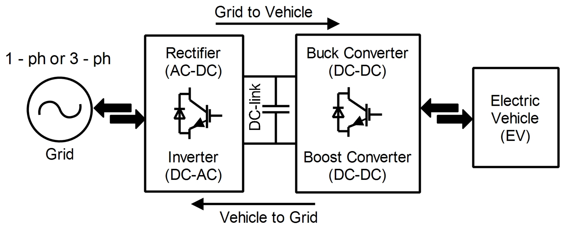
:1. Introduction
- A CCM-control-based totem pole PFC offers simple structure with higher efficiency in bidirection mode to charge and discharge the EV batteries in G2V and V2G modes, respectively.
- Due to the use of SiC device, totem pole converter is capable of operating at the high switching frequency, which reduces the size of the interfacing inductor and achieve higher efficiency as well.
- An optimized switching frequency has been analysed to obtain the high efficiency and power density.
- At an optimized switching frequency, a small sized interfacing inductor achieves lower THD.
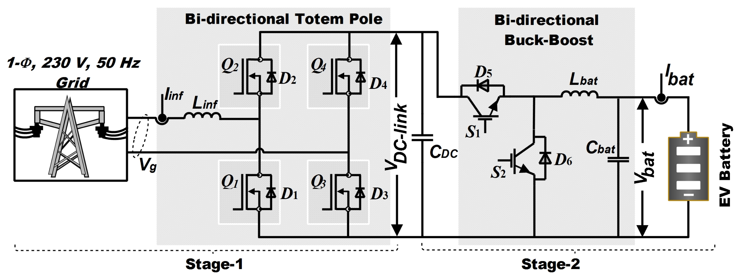
2. Brief Detail and Parameter Design
2.1. Inductor Design
2.2. Output or DC-Link Capacitor Design
2.3. Switching Frequency
2.4. Bidirectional DC-DC Converter Design
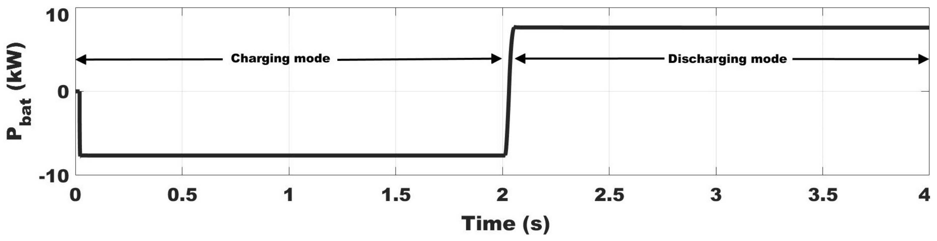
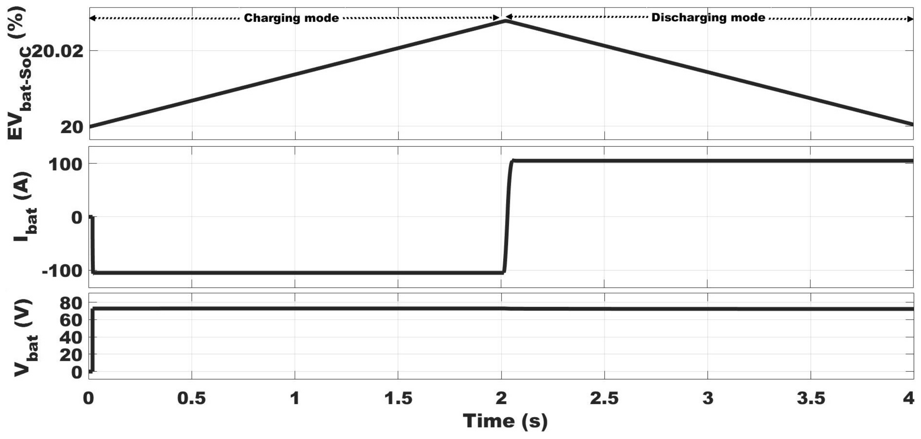
2.4.1. Charging Mode
2.4.2. Discharging Mode
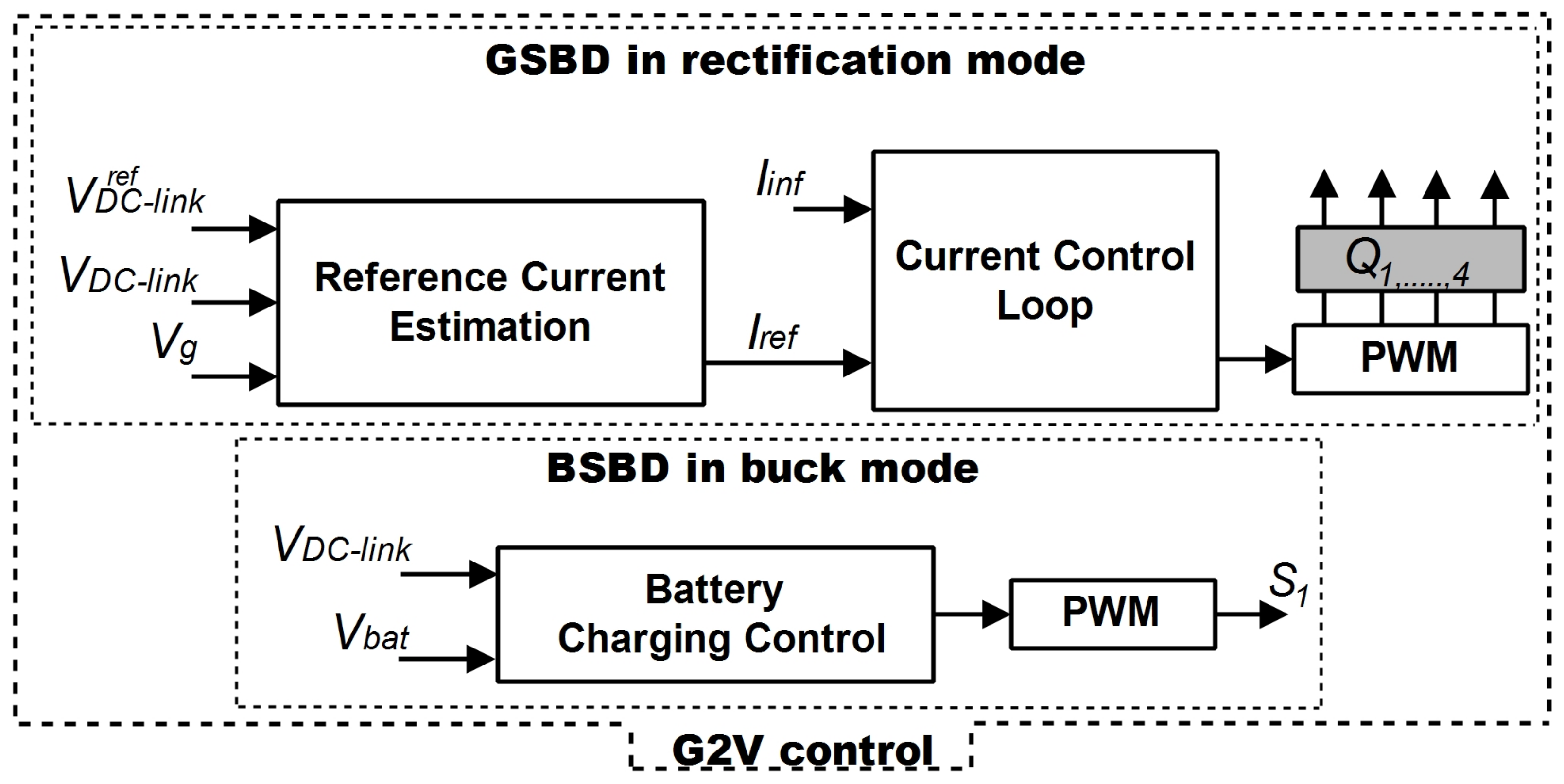
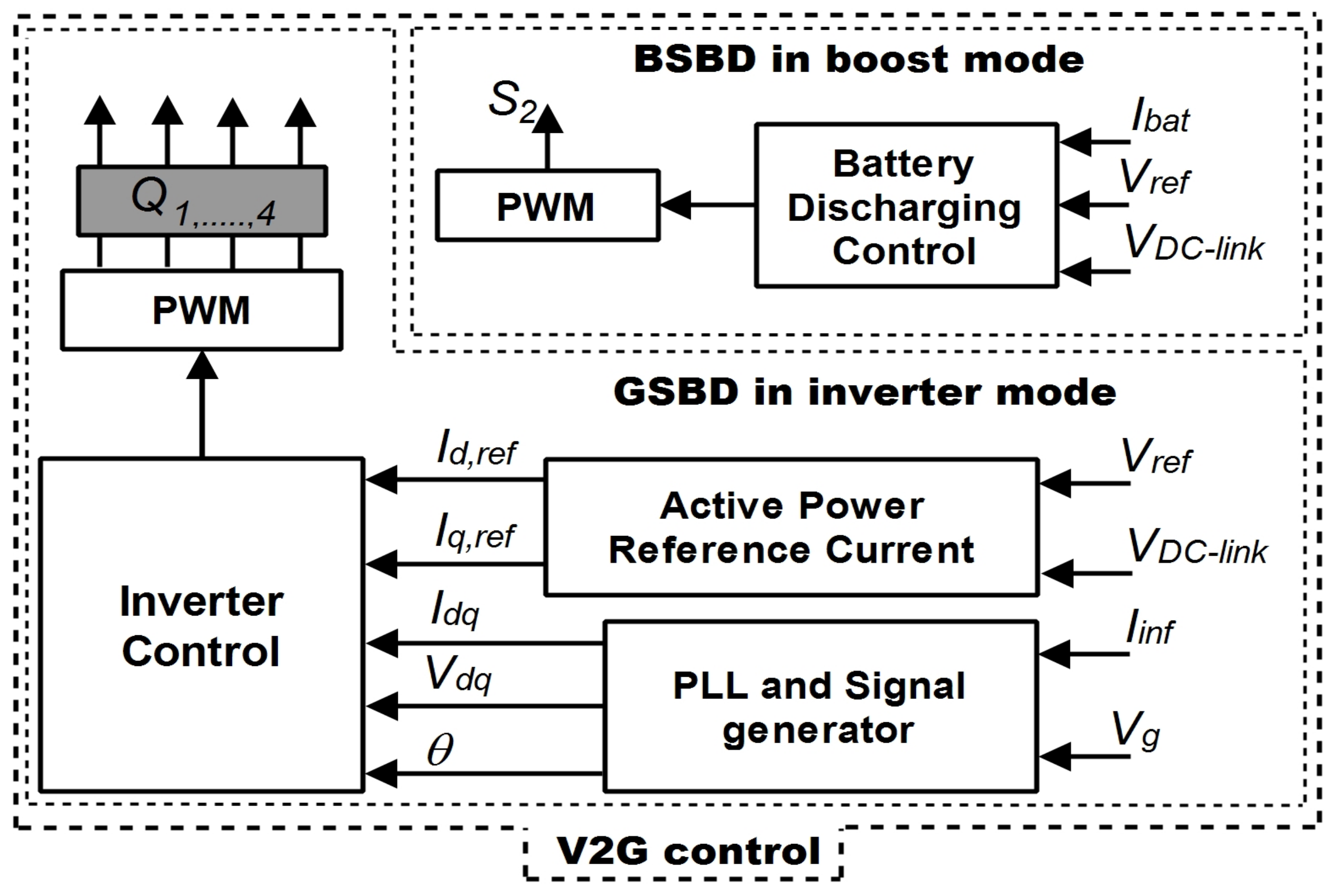
3. System Control
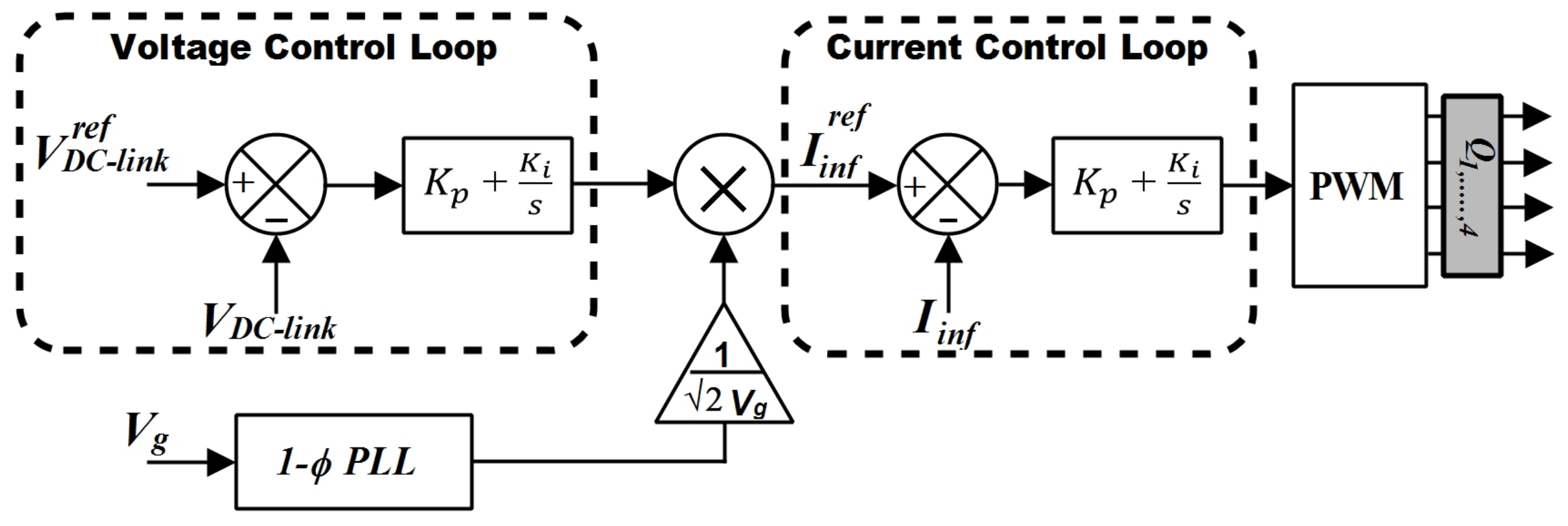
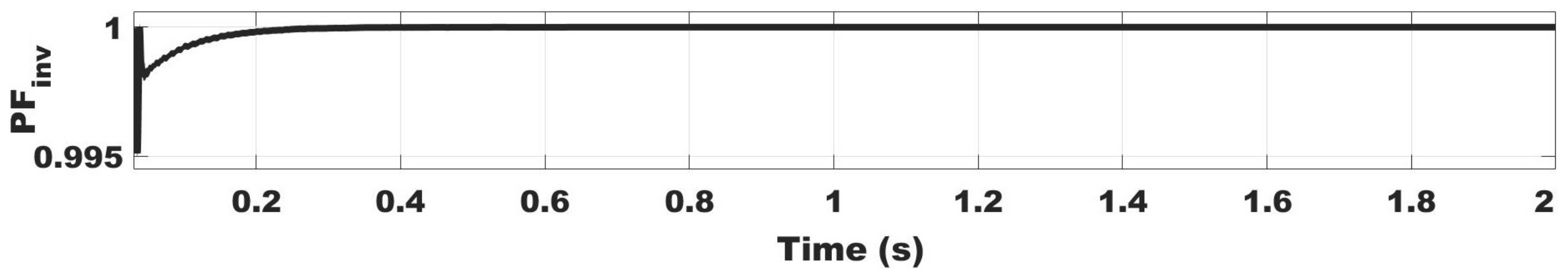
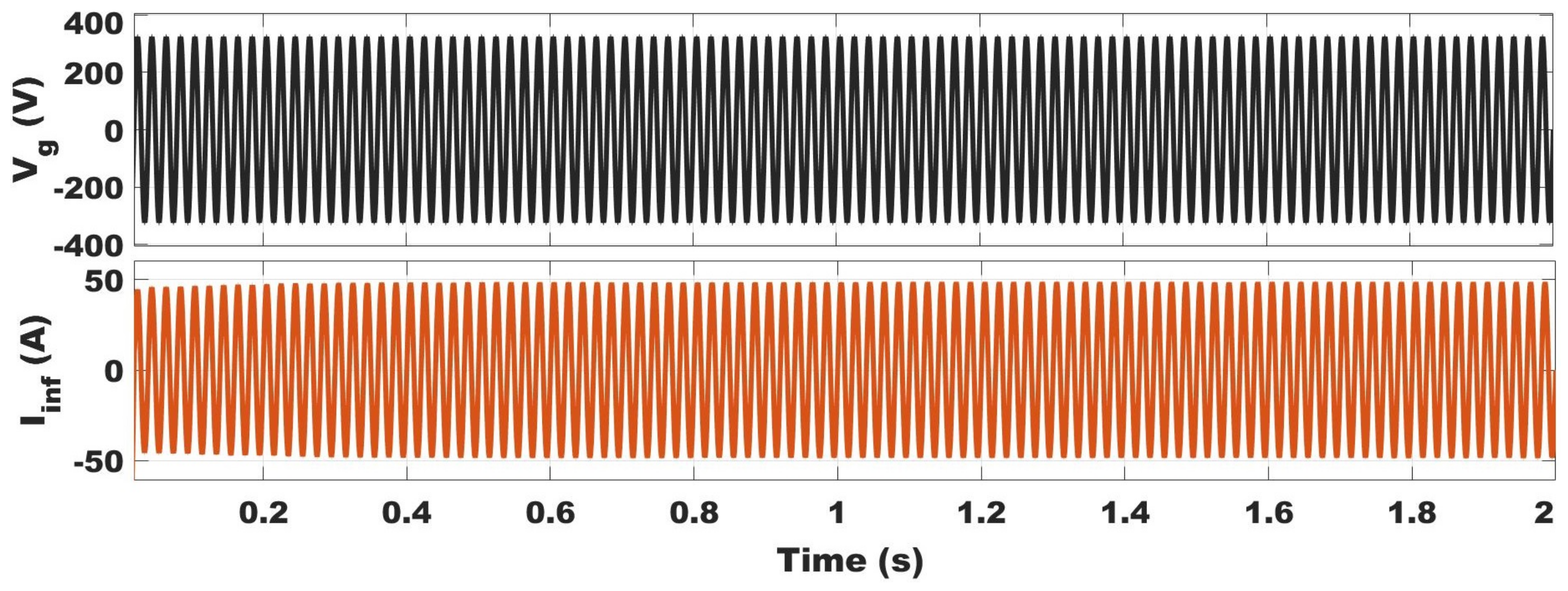
3.1. Grid-to-Vehicle Control
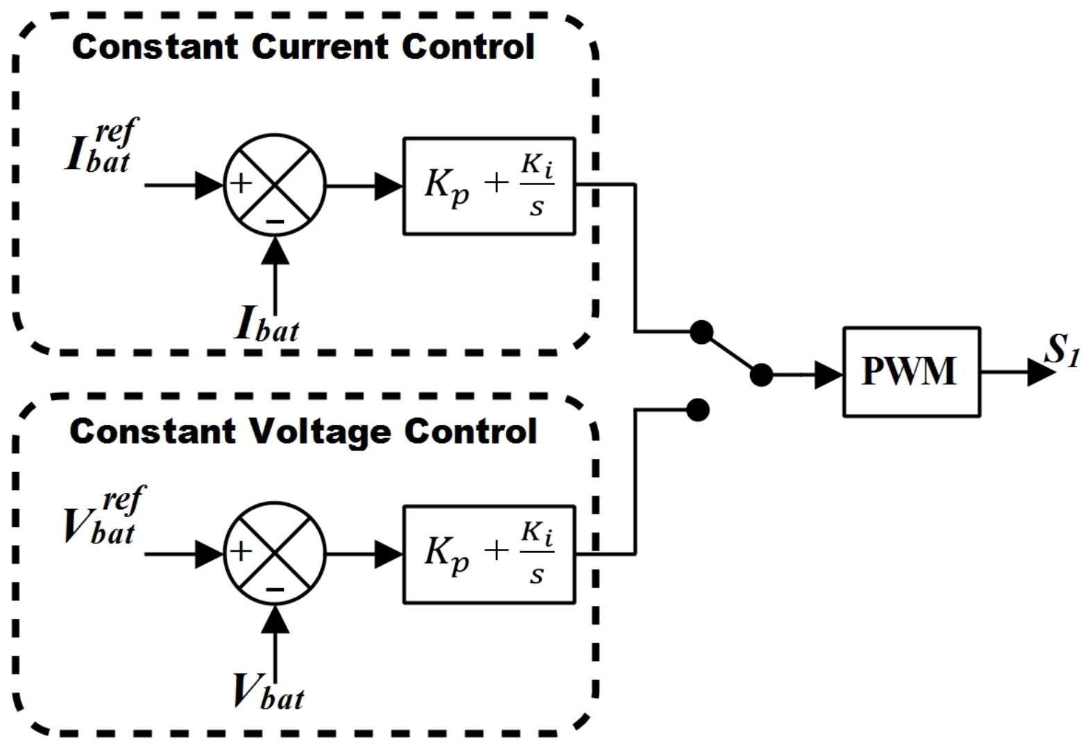
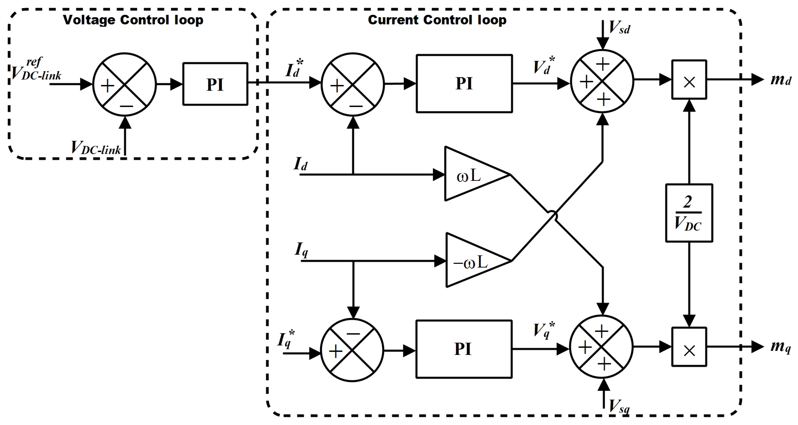
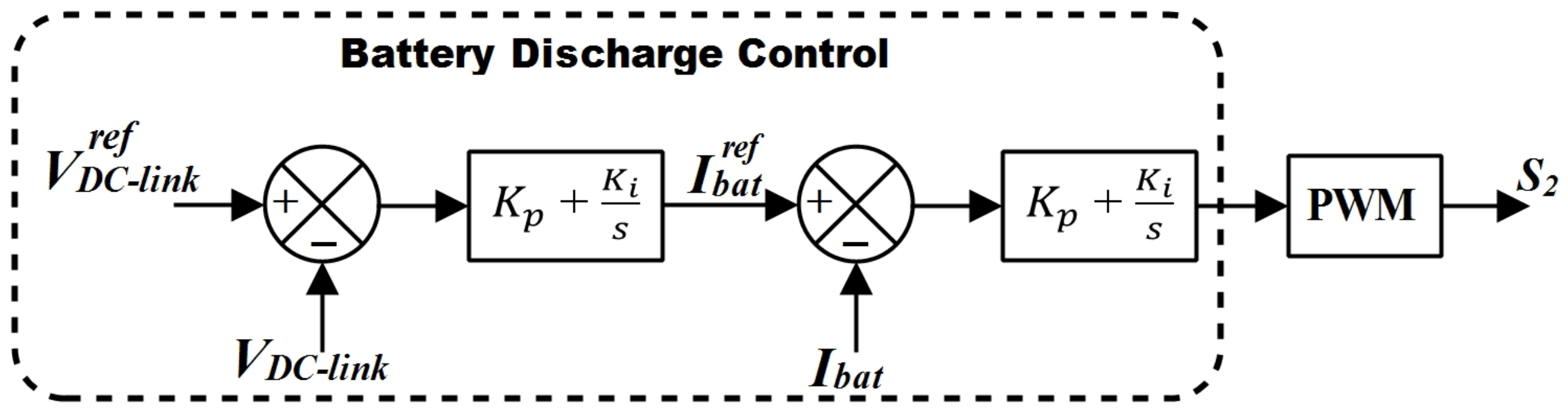
3.2. Vehicle-to-Grid Control
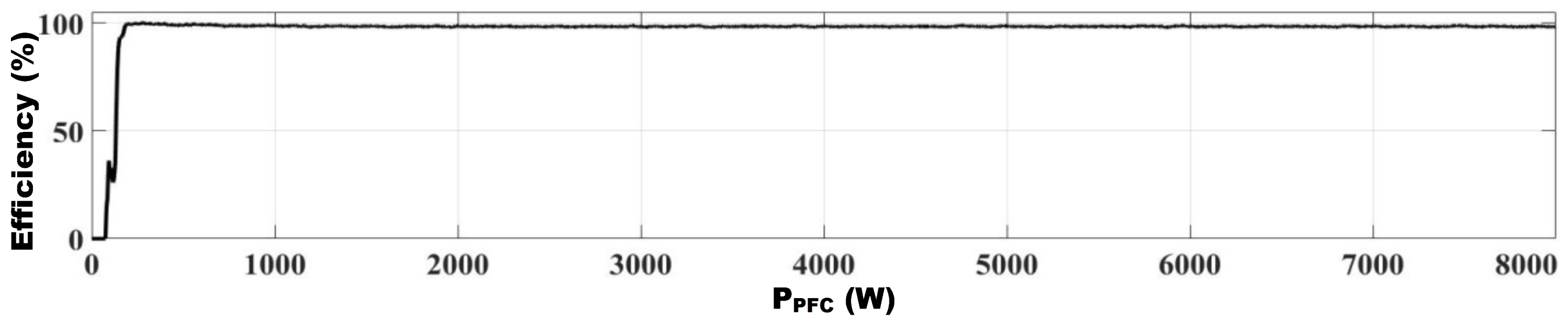
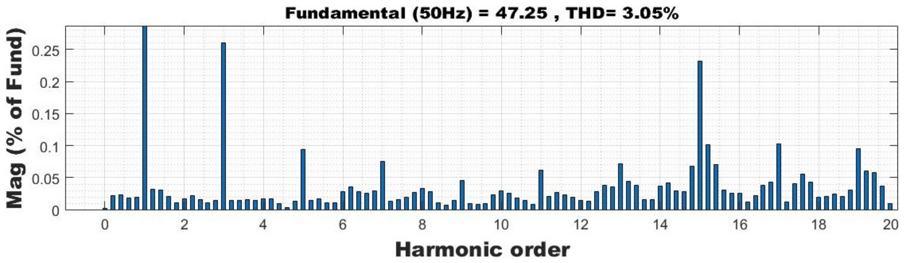
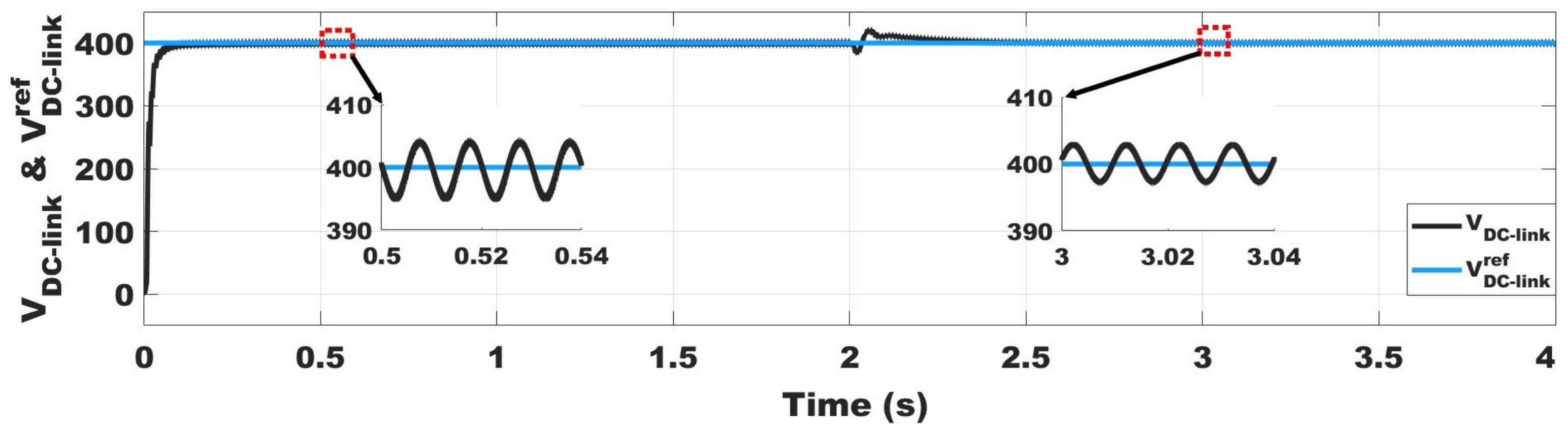
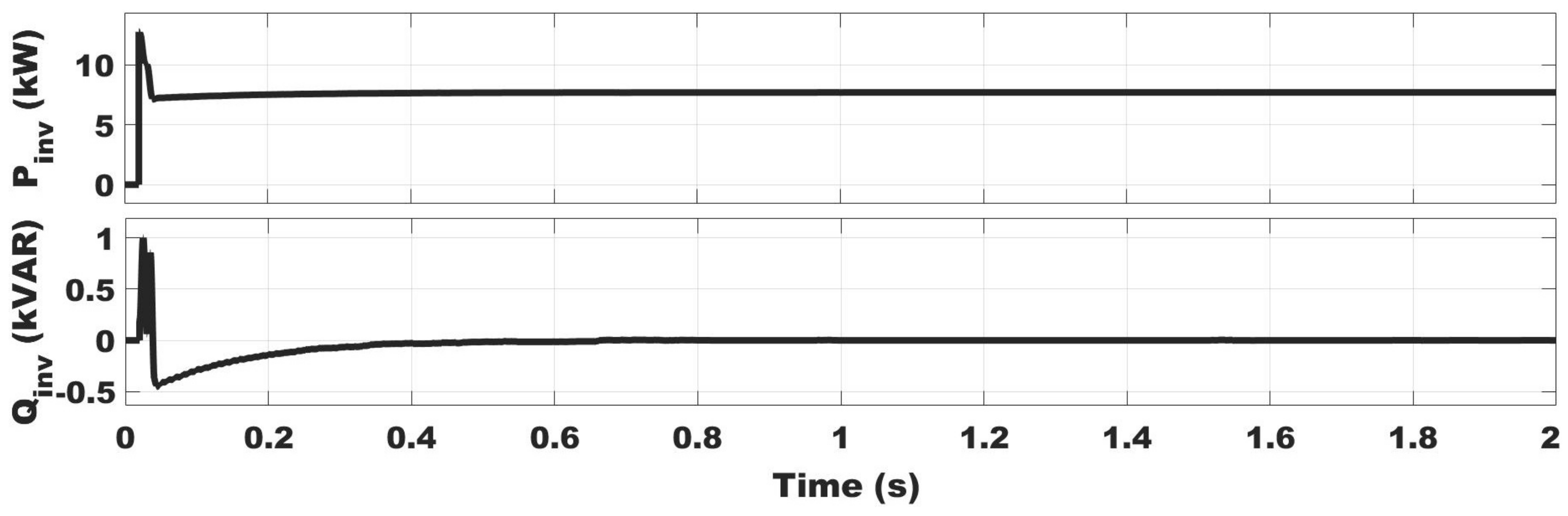
4. Result and Discussion
4.1. Performance in G2V Mode
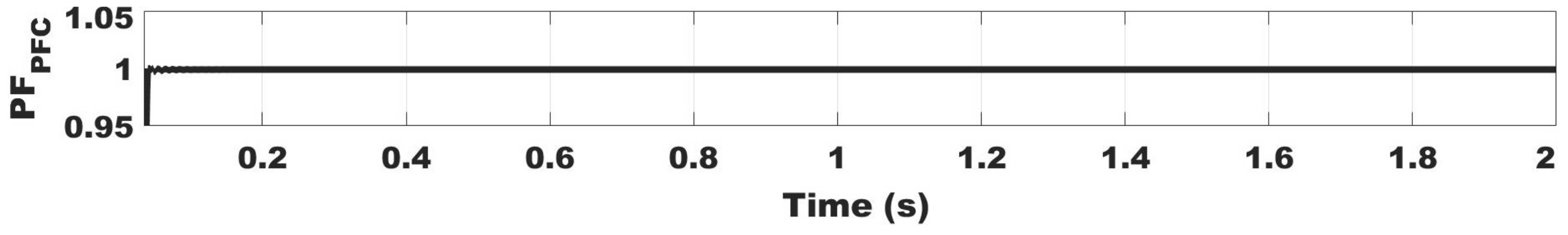
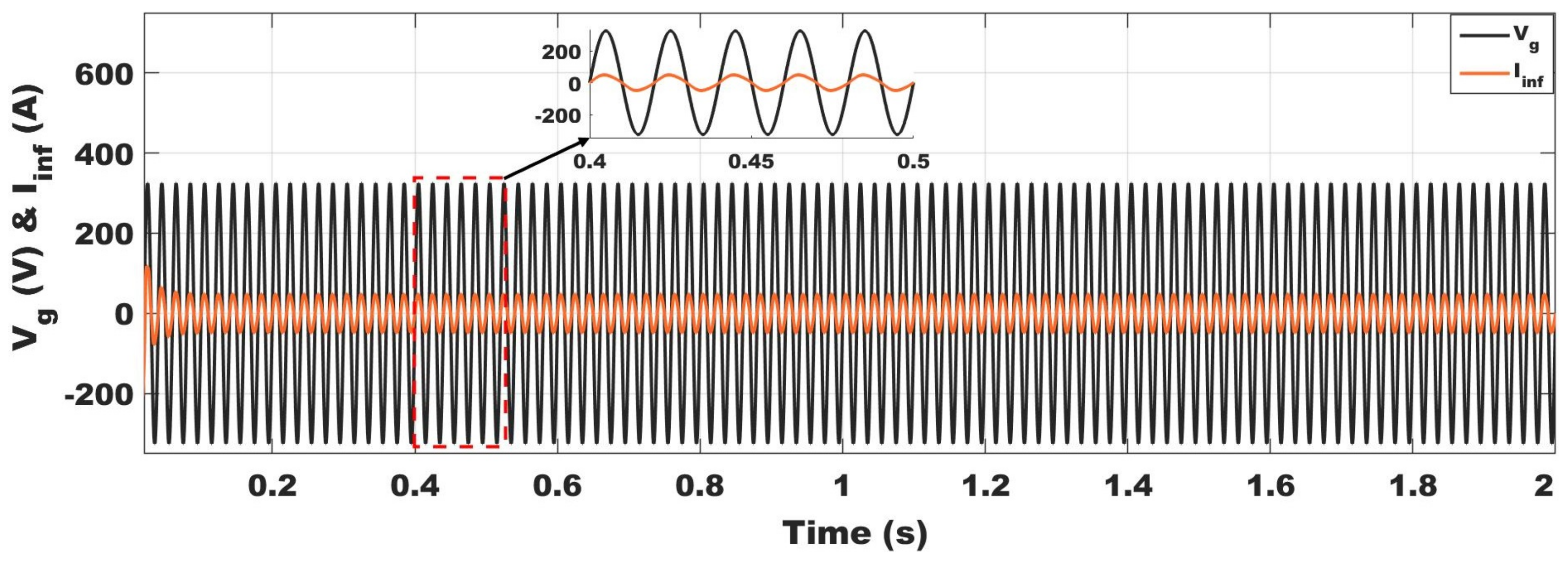
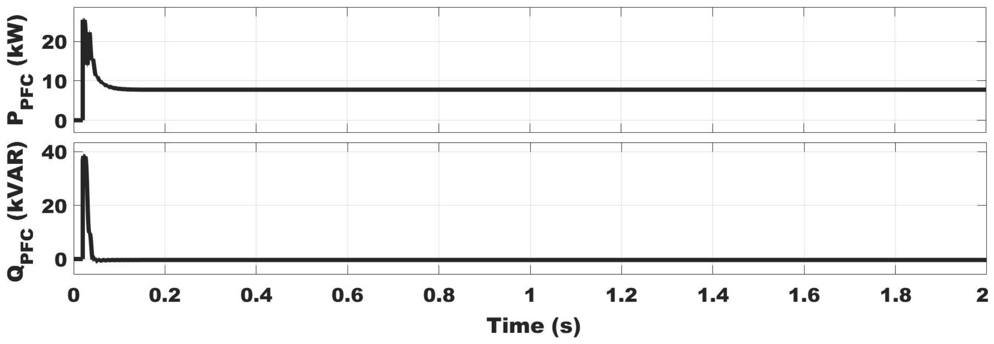
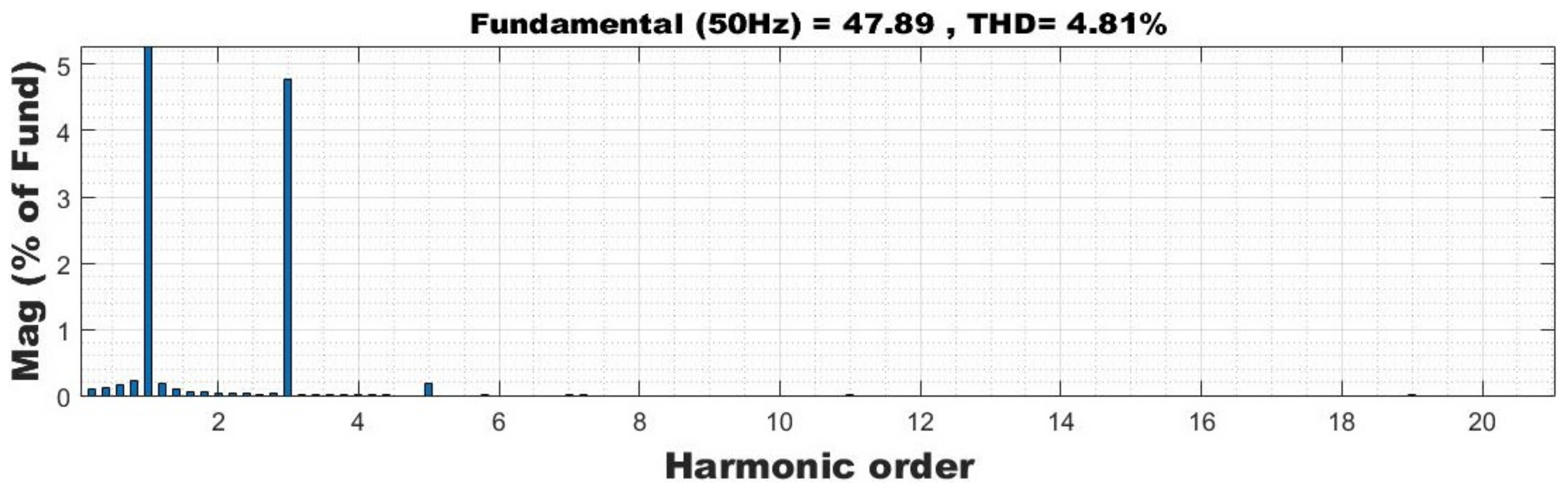
4.2. Performance in V2G Mode
5. Conclusions
Author Contributions
Funding
Institutional Review Board Statement
Informed Consent Statement
Data Availability Statement
Acknowledgments
Conflicts of Interest
Appendix A. Power Loss Calculation
Appendix B. Control Parameters
References
- Bohn, T. Plug-in Electric (PEV) Standards, Upcoming PEVs/Features, Charging System Overview. Technical Report. 2012. Available online: https://www.yumpu.com/en/document/view/6096860/plug-in-electric-vehicle-pev-standards-upcoming-pevs-eere (accessed on 29 December 2021).
- Yuan, J.; Dorn-Gomba, L.; Callegaro, A.D.; Reimers, J.; Emadi, A. A Review of Bidirectional On-Board Chargers for Electric Vehicles. IEEE Access 2021, 9, 51501–51518. [Google Scholar] [CrossRef]
- Yilmaz, M.; Krein, P.T. Review of Battery Charger Topologies, Charging Power Levels, and Infrastructure for Plug-In Electric and Hybrid Vehicles. IEEE Trans. Power Electron. 2013, 28, 2151–2169. [Google Scholar] [CrossRef]
- Lacroix, S.; Laboure, E.; Hilairet, M. An integrated fast battery charger for Electric Vehicle. In Proceedings of the 2010 IEEE Vehicle Power and Propulsion Conference, Lille, France, 1–3 September 2010; pp. 1–6. [Google Scholar] [CrossRef]
- Grenier, M.; Hosseini Aghdam, M.G.; Thiringer, T. Design of on-board charger for plug-in hybrid electric vehicle. In Proceedings of the 5th IET International Conference on Power Electronics, Machines and Drives (PEMD 2010), Brighton, UK, 19–21 April 2010; pp. 1–6. [Google Scholar] [CrossRef]
- Navinchandran, S.; Sujith, M. Bidirectional On-Board Single Phase Electric Vehicle Charger with High Gain Boost Converter for V2G Application. In Proceedings of the 2020 Fourth International Conference on Inventive Systems and Control (ICISC), Coimbatore, India, 8–10 January 2020; pp. 363–368. [Google Scholar] [CrossRef]
- Yong, J.Y.; Ramachandaramurthy, V.K.; Tan, K.M.; Mithulananthan, N. Bidirectional electric vehicle fast charging station with novel reactive power compensation for voltage regulation. Int. J. Electr. Power Energy Syst. 2015, 64, 300–310. [Google Scholar] [CrossRef]
- Skouras, T.A.; Gkonis, P.K.; Ilias, C.N.; Trakadas, P.T.; Tsampasis, E.G.; Zahariadis, T.V. Electrical Vehicles: Current State of the Art, Future Challenges, and Perspectives. Clean Technol. 2020, 2, 1–16. [Google Scholar] [CrossRef] [Green Version]
- Youn, H.S.; Park, J.S.; Park, K.B.; Baek, J.I.; Moon, G.W. A Digital Predictive Peak Current Control for Power Factor Correction With Low-Input Current Distortion. IEEE Trans. Power Electron. 2016, 31, 900–912. [Google Scholar] [CrossRef]
- Martinez, R.; Enjeti, P. A high-performance single-phase rectifier with input power factor correction. IEEE Trans. Power Electron. 1996, 11, 311–317. [Google Scholar] [CrossRef]
- Ferrari de Souza, A.; Barbi, I. A new ZVS semiresonant high power factor rectifier with reduced conduction losses. IEEE Trans. Ind. Electron. 1999, 46, 82–90. [Google Scholar] [CrossRef]
- Wang, C.M. A novel zero-Voltage-switching PWM boost rectifier with high power factor and low conduction losses. IEEE Trans. Ind. Electron. 2005, 52, 427–435. [Google Scholar] [CrossRef]
- Liu, B.; Davari, P.; Blaabjerg, F. An Optimized Hybrid Modulation Scheme for Reducing Conduction Losses in Dual Active Bridge Converters. IEEE J. Emerg. Sel. Top. Power Electron. 2021, 9, 921–936. [Google Scholar] [CrossRef]
- Huiping, Y.; Lei, X.; Shiben, M.; Zhifu, W. The study of the on-board charger with the bridgeless PFC. In Proceedings of the 2011 4th International Conference on Power Electronics Systems and Applications, Hong Kong, China, 8–10 June 2011; pp. 1–3. [Google Scholar] [CrossRef]
- Kushwaha, R.; Singh, B. Power Factor Improvement in Modified Bridgeless Landsman Converter Fed EV Battery Charger. IEEE Trans. Veh. Technol. 2019, 68, 3325–3336. [Google Scholar] [CrossRef]
- Dixit, A.; Pande, K.; Gangavarapu, S.; Rathore, A.K. DCM-Based Bridgeless PFC Converter for EV Charging Application. IEEE J. Emerg. Sel. Top. Ind. Electron. 2020, 1, 57–66. [Google Scholar] [CrossRef]
- Li, S.; Deng, J.; Mi, C.C. Single-Stage Resonant Battery Charger With Inherent Power Factor Correction for Electric Vehicles. IEEE Trans. Veh. Technol. 2013, 62, 4336–4344. [Google Scholar] [CrossRef]
- Singh, B.; Kushwaha, R. An EV battery charger with power factor corrected bridgeless zeta converter topology. In Proceedings of the 2016 7th India International Conference on Power Electronics (IICPE), Patiala, India, 17–19 November 2016; pp. 1–6. [Google Scholar] [CrossRef]
- Pinto, J.G.; Monteiro, V.; Gonçalves, H.; Exposto, B.; Pedrosa, D.; Couto, C.; Afonso, J.L. Bidirectional battery charger with Grid-to-Vehicle, Vehicle-to-Grid and Vehicle-to-Home technologies. In Proceedings of the IECON 2013—39th Annual Conference of the IEEE Industrial Electronics Society, Vienna, Austria, 10–13 November 2013; pp. 5934–5939. [Google Scholar] [CrossRef] [Green Version]
- Kisacikoglu, M.C.; Kesler, M.; Tolbert, L.M. Single-Phase On-Board Bidirectional PEV Charger for V2G Reactive Power Operation. IEEE Trans. Smart Grid 2015, 6, 767–775. [Google Scholar] [CrossRef]
- Fahem, K.; Chariag, D.E.; Sbita, L. On-board bidirectional battery chargers topologies for plug-in hybrid electric vehicles. In Proceedings of the 2017 International Conference on Green Energy Conversion Systems (GECS), Hammamet, Tunisia, 23–25 March 2017; pp. 1–6. [Google Scholar] [CrossRef]
- Bolte, S.; Schafmeister, F.; Böcker, J. Bidirectional Resonant Converter with Integrated Magnetics for On-Board Chargers. In Proceedings of the 2019 IEEE 28th International Symposium on Industrial Electronics (ISIE), Vancouver, BC, Canada, 12–14 June 2019; pp. 770–774. [Google Scholar] [CrossRef]
- Nassary, M.; Orabi, M.; Ghoneima, M.; El-Nemr, M.K. Single-Phase Isolated Bidirectional AC-DC Battery Charger for Electric Vehicle—Review. In Proceedings of the 2019 International Conference on Innovative Trends in Computer Engineering (ITCE), Aswan, Egypt, 2–4 February 2019; pp. 581–586. [Google Scholar] [CrossRef]
- Sharma, A.; Sharma, S. Review of power electronics in vehicle-to-grid systems. J. Energy Storage 2019, 21, 337–361. [Google Scholar] [CrossRef]
- Blaabjerg, F.; Wang, H.; Vernica, I.; Liu, B.; Davari, P. Reliability of Power Electronic Systems for EV/HEV Applications. Proc. IEEE 2021, 109, 1060–1076. [Google Scholar] [CrossRef]
- Choi, W.; Han, D.; Morris, C.T.; Sarlioglu, B. Achieving high efficiency using SiC MOSFETs and reduced output filter for grid-connected V2G inverter. In Proceedings of the IECON 2015—41st Annual Conference of the IEEE Industrial Electronics Society, Yokohama, Japan, 9–12 November 2015; pp. 003052–003057. [Google Scholar] [CrossRef]
- Xue, L.; Shen, Z.; Boroyevich, D.; Mattavelli, P.; Diaz, D. Dual Active Bridge-Based Battery Charger for Plug-in Hybrid Electric Vehicle With Charging Current Containing Low Frequency Ripple. IEEE Trans. Power Electron. 2015, 30, 7299–7307. [Google Scholar] [CrossRef] [Green Version]
- Zhang, Z.; Yao, K.; Ke, G.; Zhang, K.; Gao, Z.; Wang, Y.; Ren, X.; Chen, Q. SiC MOSFETs Gate Driver With Minimum Propagation Delay Time and Auxiliary Power Supply With Wide Input Voltage Range for High-Temperature Applications. IEEE J. Emerg. Sel. Top. Power Electron. 2020, 8, 417–428. [Google Scholar] [CrossRef]
- Huang, Q.; Huang, A.Q. Review of GaN totem pole bridgeless PFC. Cpss Trans. Power Electron. Appl. 2017, 2, 187–196. [Google Scholar] [CrossRef]
- Liu, Z.; Lee, F.C.; Li, Q.; Yang, Y. Design of GaN-based MHz totem pole PFC rectifier. IEEE J. Emerg. Sel. Top. Power Electron. 2016, 4, 799–807. [Google Scholar] [CrossRef]
- Li, B.; Li, Q.; Lee, F.C.; Liu, Z.; Yang, Y. A High-Efficiency High-Density Wide-Bandgap Device-Based Bidirectional On-Board Charger. IEEE J. Emerg. Sel. Top. Power Electron. 2018, 6, 1627–1636. [Google Scholar] [CrossRef]
- Wang, X.; Jiang, C.; Lei, B.; Teng, H.; Bai, H.K.; Kirtley, J.L. Power-Loss Analysis and Efficiency Maximization of a Silicon-Carbide MOSFET-Based Three-Phase 10-kW Bidirectional EV Charger Using Variable-DC-Bus Control. IEEE J. Emerg. Sel. Top. Power Electron. 2016, 4, 880–892. [Google Scholar] [CrossRef]
- Tang, Y.; Lu, J.; Wu, B.; Zou, S.; Ding, W.; Khaligh, A. An Integrated Dual-Output Isolated Converter for Plug-in Electric Vehicles. IEEE Trans. Veh. Technol. 2018, 67, 966–976. [Google Scholar] [CrossRef]
- Wei, C.; Zhu, D.; Xie, H.; Shao, J. A 6.6 kW high power density Bidirectional EV on-board charger based on SiC MOSFETs. In Proceedings of the PCIM Europe 2019, International Exhibition and Conference for Power Electronics, Intelligent Motion, Renewable Energy and Energy Management, Nuremberg, Germany, 7–9 May 2019; pp. 246–252. [Google Scholar]
- Jia, Y.; Wu, H.; Yang, L.; Xu, X.; Liu, Y.; Yang, F.; Xing, Y. Characterization and Optimal Control of totem pole PFC Converter With High Frequency GaN HEMTs and Low Frequency Si Diodes. IEEE Trans. Ind. Electron. 2021, 68, 10740–10749. [Google Scholar] [CrossRef]
- Su, B.; Lu, Z. An Interleaved totem pole Boost Bridgeless Rectifier With Reduced Reverse-Recovery Problems For Power Factor Correction. IEEE Trans. Power Electron. 2010, 25, 1406–1415. [Google Scholar] [CrossRef]
- Zhou, L.; Wu, Y.; Honea, J.; Wang, Z. High-efficiency True Bridgeless Totem Pole PFC based on GaN HEMT: Design Challenges and Cost-effective Solution. In Proceedings of the PCIM Europe 2015, International Exhibition and Conference for Power Electronics, Intelligent Motion, Renewable Energy and Energy Management, Nuremberg, Germany, 19–20 May 2015; pp. 1–8. [Google Scholar]
- Liu, Z.; Li, B.; Lee, F.C.; Li, Q. High-Efficiency High-Density Critical Mode Rectifier/Inverter for WBG-Device-Based On-Board Charger. IEEE Trans. Ind. Electron. 2017, 64, 9114–9123. [Google Scholar] [CrossRef]
- Huang, Q.; Ma, Q.; Liu, P.; Huang, A.Q.; de Rooij, M.A. 99% Efficient 2.5-kW Four-Level Flying Capacitor Multilevel GaN totem pole PFC. IEEE J. Emerg. Sel. Top. Power Electron. 2021, 9, 5795–5806. [Google Scholar] [CrossRef]
- Yu, Z.; Xia, Y.; Ayyanar, R. A Simple ZVT Auxiliary Circuit for totem pole Bridgeless PFC Rectifier. IEEE Trans. Ind. Appl. 2019, 55, 2868–2878. [Google Scholar] [CrossRef]
- Huang, Q.; Yu, R.; Ma, Q.; Huang, A.Q. Predictive ZVS Control with Improved ZVS Time Margin and Limited Variable Frequency Range for a 99% Efficient, 130-W/in3 MHz GaN totem pole PFC Rectifier. IEEE Trans. Power Electron. 2019, 34, 7079–7091. [Google Scholar] [CrossRef]
- Liu, J.; Wiener, P. Optimal Design for High Frequency GaN-Based Totem Pole PFC; GaN Systems Inc.: Kanata, ON, Canada, 2019. [Google Scholar]
- Yu, S.Y.; Gong, X.; Wang, G.; Bhardwaj, M. Designing a High-Power Bidirectional AC/DC Power Supply Using SiC FET. 2020, pp. 1–25. Available online: www.ti.com/psds (accessed on 1 February 2022).
- Li, H.; Zhang, Z.; Wang, S.; Tang, J.; Ren, X.; Chen, Q. A 300-kHz 6.6-kW SiC Bidirectional LLC Onboard Charger. IEEE Trans. Ind. Electron. 2020, 67, 1435–1445. [Google Scholar] [CrossRef]
- Power Factor Correction (PFC) Handbook; SCILLC: Steel City, PA, USA, 2011.
- Xu, D.; Zhang, J.; Chen, W.; Lin, J.; Lee, F. Evaluation of output filter capacitor current ripples in single phase PFC converters. In Proceedings of the Power Conversion Conference-Osaka 2002 (Cat. No.02TH8579), Osaka, Japan, 2–5 April 2002; Volume 3, pp. 1226–1231. [Google Scholar] [CrossRef]
- Yao, K.; Wang, Y.; Guo, J.; Chen, K. Critical Conduction Mode Boost PFC Converter with Fixed Switching Frequency Control. IEEE Trans. Power Electron. 2018, 33, 6845–6857. [Google Scholar] [CrossRef]
- Abdel-Rahman, S.; Stückler, F.; Siu, K. PFC Boost Converter Design Guide; Infineon Application Note. 2016, Volume 2. Available online: http://www.personal.psu.edu/ahy5028/coiling/InfineonPFCCCMBoostConverterDesignGuide.pdf (accessed on 1 February 2022).
- UnitedSiC_AN0026. Performance Calculator of Single-Phase SiC Based PFC in CCM. Available online: https://unitedsic.com/fet-jet/ (accessed on 1 February 2022).
- Zhu, M. Enabling 99.3% Efficiency in 3.6 kW Totem Pole PFC Using New 750 V Gen 4 SiC FETs. 2021. Available online: https://unitedsic.com/appnotes/Enabling-efficiency-in-Totem-pole-PFC-using-750V-Gen-4-SiC-FETs.pdf (accessed on 1 February 2022).


| G2V/Charging Mode | |
|---|---|
| and | 230 V and 50 Hz |
| or | 400 V |
| 7.7 kW | |
| 65 kHz | |
| 20% | |
| 5% | |
| target | > |
| target | > |
| V2G/Discharging Mode | |
| 400 V | |
| and | 230 V and 50 Hz |
| 7.7 kW | |
| 65 kHz | |
| < | |
| Passive Components | Value |
|---|---|
| 5 mH | |
| 8200 F | |
| 5 mH | |
| 20,000 F |
| Loss Components | Value |
|---|---|
| Interfacing inductor loss | – |
| DC-link capacitor loss | 5.26 W |
| Switching loss | 52.4 W |
| Conduction loss | 70.8 W |
| Total power loss | 128.46 W |
| Output-rated power | 7700 W |
| Efficiency | 98.38% |
Publisher’s Note: MDPI stays neutral with regard to jurisdictional claims in published maps and institutional affiliations. |
© 2022 by the authors. Licensee MDPI, Basel, Switzerland. This article is an open access article distributed under the terms and conditions of the Creative Commons Attribution (CC BY) license (https://creativecommons.org/licenses/by/4.0/).
Share and Cite
Kumar, V.; Yi, K. Single-Phase, Bidirectional, 7.7 kW Totem Pole On-Board Charging/Discharging Infrastructure. Appl. Sci. 2022, 12, 2236. https://doi.org/10.3390/app12042236
Kumar V, Yi K. Single-Phase, Bidirectional, 7.7 kW Totem Pole On-Board Charging/Discharging Infrastructure. Applied Sciences. 2022; 12(4):2236. https://doi.org/10.3390/app12042236
Chicago/Turabian StyleKumar, Vinit, and KangHyun Yi. 2022. "Single-Phase, Bidirectional, 7.7 kW Totem Pole On-Board Charging/Discharging Infrastructure" Applied Sciences 12, no. 4: 2236. https://doi.org/10.3390/app12042236
APA StyleKumar, V., & Yi, K. (2022). Single-Phase, Bidirectional, 7.7 kW Totem Pole On-Board Charging/Discharging Infrastructure. Applied Sciences, 12(4), 2236. https://doi.org/10.3390/app12042236