Article

Wind-Induced Response and Its Controlling of Long-Span Cross-Rope Suspension Transmission Line

1
Key Laboratory of New Technology for Construction of Cities in Mountain Area, Ministry of Education, Chongqing University, Chongqing 400030, China
2
College of Civil Engineering, Chongqing University, Chongqing 400030, China
3
Chongqing Steel Structure Industry Co., Ltd., Chongqing 400080, China
*
Author to whom correspondence should be addressed.
Appl. Sci. 2022, 12(3), 1488; https://doi.org/10.3390/app12031488
Submission received: 30 December 2021 / Revised: 21 January 2022 / Accepted: 26 January 2022 / Published: 29 January 2022

Abstract

:
In mountainous areas, the installation of steel towers was the major obstacle to the construction of transmission lines. In long-span cross-rope suspension (CRS) structures, the conductors are supported by hundreds-meters-long suspension cables crossing valleys instead of steel towers. Though long-span CRS is an innovative structural system, its structural performance needs to be clarified. Firstly, an assembled FE model was established based on initial deformed components for long-span cross-rope suspension structure. The wind load response of long-span cross-rope suspension structure with different lengths or number of spans was established and analyzed. Vortex-induced vibration (VIV), which was the major factor regarding fatigue and service life, and its controlling by Stockbridge damper for a long-span CRS were discussed. The numerical simulation results showed that the tensile force of the suspension cable increased with the length and number of spans of the conductor. In addition, considering the ice covering the transmission line, the interaction between the wind load and ice load induced the nonlinear lateral deformation characteristics of the conductor. Moreover, the vibration characteristics of the conductor in the long-span CRS were studied and compared with the traditional tower-line system. An analysis of the long-span CRS with a Stockbridge damper showed that additional dampers were essential for controlling the maximum dynamic bending stress of conductors at both ends.

1. Introduction

A cross-rope suspension (CRS) system is a widely used type of transmission line structure that was developed from a guyed V-tower system. CRS was firstly proposed in 1974 [1]. In the CRS system, the transmission line is supported by transversally crossing suspension cables connected to the towers on both ends. Thus, the conventional steel towers were removed, and the CRS system was always considered to be optimized compared with the line-tower system. Moreover, the CRS system was more suitable in mountainous areas, which largely improved the construction difficulty and efficiency. The CRS structural system built in Cape Town, South Africa, was called the “invisible tower line” [2]. Its engineering experience indicated that CRS could significantly reduce the visual impact on the surrounding environment and protect the original natural landscape. Generally, the span of the suspension cable is limited to 200 m. For the application in a complex environment, the span of CRS was expanded beyond 1000 m while insulators were installed between each pair of conductors, which became a novel long-span cross-rope suspension structural system, as shown in Figure 1 [3].
The finite element method (FEM) was widely adopted for analyzing complex flexible structures with large geometric deformation so far, as well as CRS [4]. The analysis of the initial shape (mechanical sag) of suspension cable and conductors was the basis of further dynamic analysis of long-span CRS. Jia and Liu [5] established the initial form-finding method of overhead transmission lines, which is based on the form-finding of cable structures. Based on the FE model of CRS, dynamic properties and structural responses induced by wind load were studied. CRS transmission line structures were designed to withstand several different load cases. For mountainous environments, extreme wind and combined wind and ice in cold climates governed the design load for CRS. Keyhan presented a new method to determine wind loading on transmission line conductors based on fluid–structure interaction analysis [6]. Based on the historical weather data in Ontario, Krishnasamy analyzed the wind load on bare and ice-covered conductors [7]. Lalonde used the finite element strategy and developed the study of aluminum conductor steel reinforced (ACSR) by wind-induced load and compared it with experimental data [8].
Wind-induced vibration and its vibration controlling measurement were the major consideration of the structural design of long-span CRS. Flexible structures, such as long cable and cable-supported structures, were susceptible to wind-induced vibration due to their strong geometric nonlinear [9,10]. Long-span CRS was considered to be a typical wind-sensitive structure, and its wind-induced vibration was always focused on by researchers. Vortex-induced vibration (VIV) was recognized as one of the most common types of wind-include vibration that occurred in overhead lines, which was attributed to the process of vortex shedding [11]. VIV significantly induced dynamic bending stress on the ends of conductors and enhanced the risk of structural failure. Models of CRS with different element types based on finite element analysis were established, and the influence of various models on the overall response of structure was compared [12]. Dampers, such as tuned mass damper, magnetorheological damper and Stockbridge damper, were adopted to provide additional energy dissipation for reducing wind-induced structural vibration, also applicable for VIV of transmission line [13]. Vaja presented an analytical model of a novel VIV damper with an increased number of resonant frequencies [14]. Generally, the maximum steady-state amplitude of the conductor during the VIV process was solved by energy balance mothed [15,16]. Therefore, the conductors’ dynamic bending stress cycle results in independent elongated deformation of each rope of conductors and further surface erosion and fatigue [17]. For flexible, long-span structures, structural and economic considerations were involved for the configuration of dampers. The optimization of dampers parameters was essential to ensure the limited vibration amplitude below the specified threshold [18,19]. Besides, though galloping was always observed in cable structures, due to its complexity, galloping in a long-span CRS will be discussed in a further study.
The CRS transmission line system was composed mainly of conductors, suspension cables and insulators. The suspension cable of CRS, which was fixed in a rigid foundation, was the main bearing structure of CRS. In order to cross the valley, the suspension cable was made of high-strength-stranded steel wire, and it spanned beyond thousands of meters. The conductors were connected to the cable by wire fittings. For the multiphase conductor, tension insulators were adopted to separate conductors from each other. A Diagram of the CRS transmission line system is shown in Figure 2.
In this paper, the recommended design parameters of long-span CRS are shown in Table 1.
For the aim of structural assessment of applying a CRS transmission line system in a mountainous area, structural responses induced by wind load were discussed in this paper. Based on the assembly modeling approach, all components of CRS were separately modeled, analyzed and finally assembled with their deformed shape and loading states. With static wind load, lateral displacement of conductor and tension of suspension cable was calculated. Considering ice-covered conductors in cold climates, by the same method, the results of bare and ice-covered cases were compared. Moreover, based on the dynamic properties of CRS, wind-induced vibration and its controlling of CRS were simulated. The effect of a Stockbridge damper on the overall vibration of CRS was studied by theoretical approach and FEM. For the needs of practical application, the factors, including configuration and mass of the Stockbridge damper, span length of the suspension cable and conductor and the number of spans of the conductor, were assessed for further discussion on vortex-induced vibration controlling of CRS.

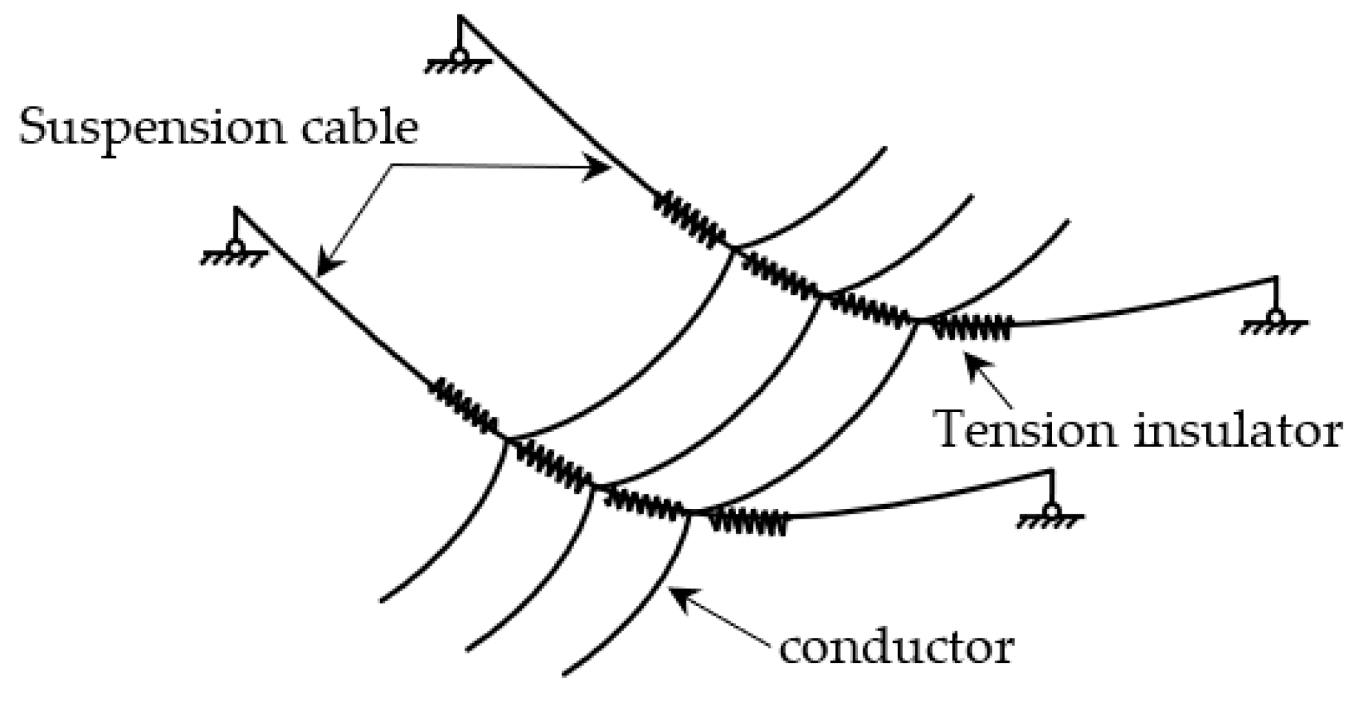
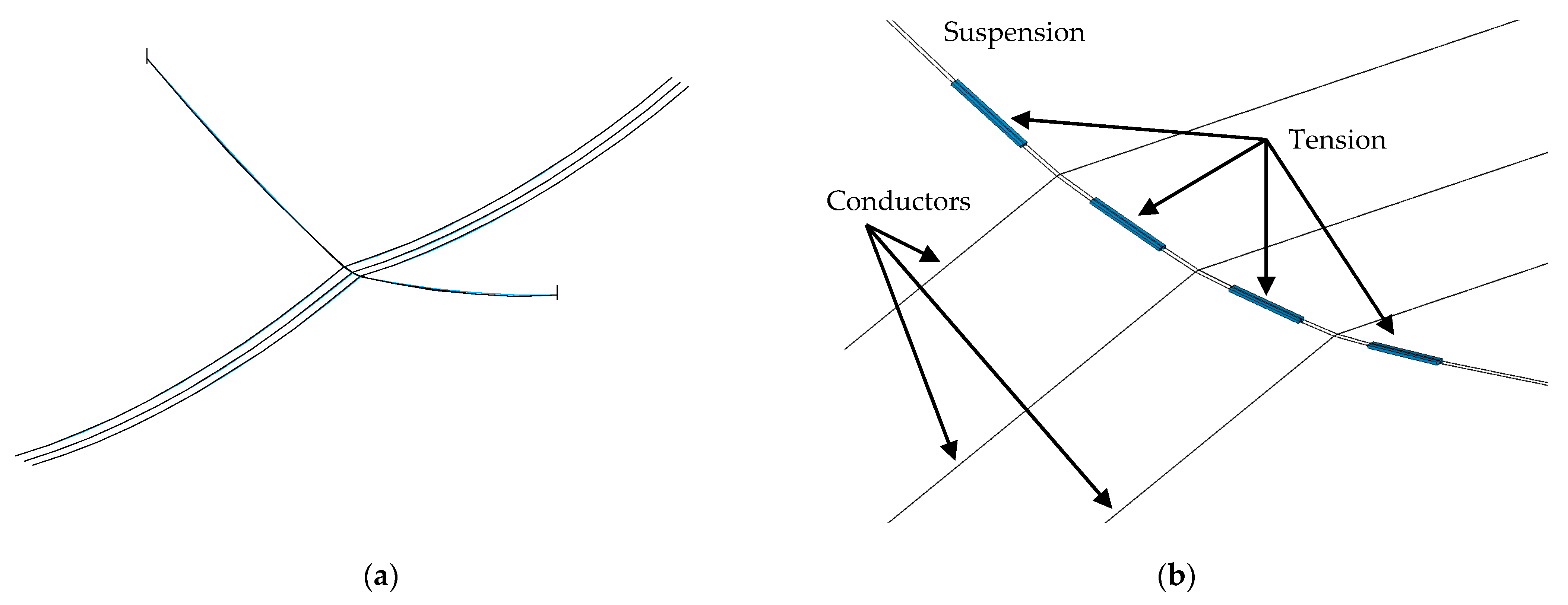
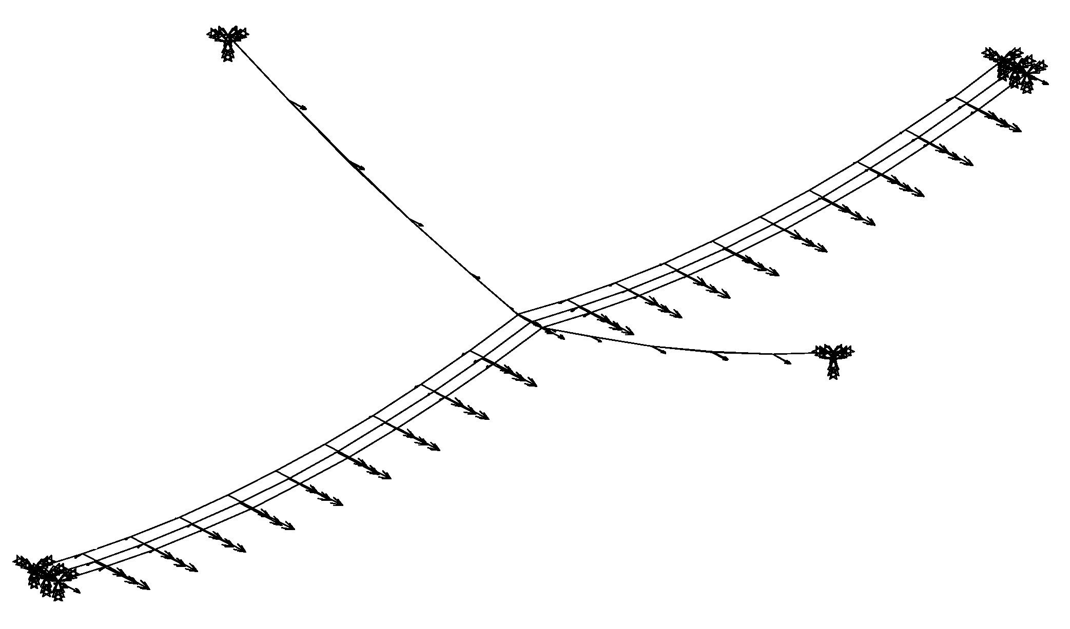
2. Modeling of Long-Span CRS

As described above, the CRS was composed of suspension cable, conductor, insulator and anchorage while guyed masts towers were removed. The suspension cable supported the conductors and was anchored on both ends. The suspension cable and conductor, the main components of CRS, made a complex flexible structural system. It was always an issue modeling complex flexible structural systems with large deformation due to convergence problems when considering geometrical nonlinearity. This paper presents an assembly modeling approach where the components of the CRS and their deformed shape and loading states were separately analyzed and finally assembled. Commercial finite element software, ANSYS, was adopted for the mentioned modeling process. All members were modeled by a two-node link element type in three-dimensional space, which means only tensile force and strain were considered for each element, and the bending and torsion stiffness were ignored. Regarding the frequency of principal vibration mode, a minimum of 100 divisions for a whole segment of cable or conductor was essential [20].
In order to obtain stable and accurate computation, the whole structure was divided into several individual parts, including suspension cables and conductors. Those substructures were computed separately and then assembled into a whole system. Consequently, displacement and deformation of each node and element were calculated in their substructures and inputted as initial conditions for the whole assembled structural system. Therefore, stability and accuracy of computation were achieved in this way.
The deformed shape of the suspension cable and conductor under initial static load were calculated, respectively. The initial shape function of conductor with uniform load was simplified to a parabola, which was defined by a sag in middle span, and was given as follows:
y = 4 x f m ( 1 x / l ) / l
where x is the distance from starting point (m), l is the span (m) and f m is the sag in the midspan (m):
f m = γ l 2 / 8 σ 0 cos β
where γ is uniform load in per length and section (N/m mm2), σ 0 is horizontal stress of the conductor (N/mm2), β is the angle of height difference, tan β = h / l , where h is the height difference between two suspension points (m). It was noticed that horizontal stress σ 0 could be calculated from design tensile force T , which was considered as the control parameter for calculating the deformed shape of the suspension cable and conductor. Approximated parabola shapes of each substructure were calculated by taking tensile force T into Equation (2) and then Equation (1). Coordinates of nodes and tensile stress of each element were input to finite element software program as initial conditions for static analysis. Then, the approximate shape of each substructure obtained was exported for further calculation.
The process of an assembly modeling approach for the CRS transmission line is shown in Figure 3. Firstly, the finite element models of conductor and suspension cable were established, respectively, the material properties were input, and the initial shapes of the conductor and suspension cable were calculated with the design tension or sag as the control parameters. Secondly, the conductor and suspension cable were combined through rigid constraints according to the design requirement, and then the overall gravity stability state was calculated. The gravity stability of the whole suspension structure was obtained. Finally, the stability of the structure under gravity was the convergence goal, and whether the tension and sag met the initial design requirements was judged at the same time. This approach combined essential dimensions for modeling, including spans, the height difference of both ends and sags of the conductor and suspension cable. The sag in the middle span determined the tensile force of the cable and conductor. By taking tensile force as convergence criterion, deformed shapes of each substructure were obtained by iteration calculation. The whole FE model of a long-span CRS was rebuilt based on displacements and deformations of all nodes and elements recorded. Each substructure of multi-span CRS was calculated separately and assembled into every span, as shown in Figure 4.
The detail of the connection between suspension cable, conductor and insulators is shown in Figure 5.

3. Dynamic Properties

In this paper, by comparing the results of frequencies of principal vibration modes of the two-span CRS with various mesh sizes, meshing with 100 elements for a single span of conductor and cable was adopted in terms of the balance of accuracy and computing efficiency [20]. The results of vibration modes and natural frequencies of a single conductor are shown in Figure 6, and results of multi-span CRS are shown in Figure 7, Figure 8, Figure 9 and Figure 10. The results showed the frequencies of similar vibration modes in multi-span CRS. Compared with one segment of an individual conductor, CRS showed a significant difference in the first asymmetric vertical bending mode, in which lateral deformation of cable was observed and the axial rigidity of conductors was released.

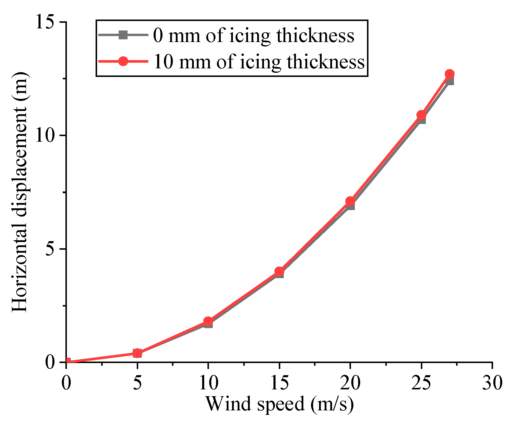
4. Comparison of Wind Loads on Bare and Ice-Covered Overhead Conductors

4.1. Expression of Wind Load

In this chapter, for simplicity, the wind load was considered as static wind load. Based on wind profile, the average speed of wind in different altitudes was calculated from [21]:
v ¯ ( z ) = v ¯ b ( z z b ) α
where v ¯ ( z ) is the average speed of winds in target altitude (m/s), v ¯ b is the standard speed of wind (m/s), z is the target altitude (m) and z b is standard target altitude (m). α is the ground roughness exponent.
The static wind load on a bare conductor or suspension cable from:
F g = 1 2 ρ v 2 C D A n
where F g is static wind load in structure in per length (N/m), ρ is the density of the air (1.25 kg/m3 in this case), v ¯ is the average speed of the winds in target altitude calculated from (3), C D is the drag coefficient of given cross-section and A n is the projected area of structure along wind direction in per length (m2/m). For the long-span CRS, the cross-section of the suspension cable and conductor are smooth circular, and their length is significantly longer than their diameter. Thus their drag coefficient C D was given as 0.6 according to available experimental data.
The most unfavorable condition was considered to be when the wind direction was perpendicular to the conductor or suspension cable. The calculation condition of wind speed ranged from 0 m/s to 27 m/s, which is the maximum wind speed in a 50-year-based-period for this case. A diagram of wind loading is shown in Figure 11.

4.2. Ice Load on Conductor and Suspension Cable

The ice caused the increase in conductor cross-section area and weight per length, which caused the increase in self-gravity load and wind load and, accordingly, the larger tensile force of the conductor. For the long-span CRS, the change in ice thickness and wind speed bring about significant changes in internal force and deformation of the structure. Especially under the combined effect of ice and wind, the conductor and suspension cable were subject to greater internal force, which endangered its structural safety. It is important to analyze the wind resistance of the long-span CRS with ice on the structure. For simplification, the conductor, suspension cable and tension insulator were considered to be uniformly iced, as shown in Figure 12.
In the FE model, the iced cross-section parameters were redefined, and equivalent density was calculated from [21]:
ρ e q = ρ r π d r 2 + ρ i c e π ( 4 d i 2 + 4 d i d r ) π ( d r + 2 d i ) 2
where ρ r is the density of conductor or suspension cable (kg/m3), ρ i c e is the density of ice (kg/m3), d i is the ice thickness (m), d r is the diameter of conductor or suspension cable (m).

4.3. Result

As described above, the major concern in static wind load conditions was the internal force and deformation of the structure. Typical deformation of the long-span CRS with static wind load is shown in Figure 13.
Tensile force results of suspension cables in different wind speeds were obtained. Based on the structure stability status of self-weight, the increment of tensile force of the suspension cable is shown in Figure 14. The results showed that the tension force of the suspension cable increased with wind speed. While ice thickness increased to 10 mm, the increment was more remarkable than no ice. It is mainly because of a larger windward area of the iced conductor, which leads to a larger wind load. Wind load increased with the span length of the conductor. In order to study the influence of the span length of the conductor on the tensile force of suspension cables, the FE models of long CRS with a different span length of the conductor were analyzed. The results in Figure 15 show that the tensile force of the suspension cable increased with a span length of the conductor, and the increment was marked more while the conductor was iced.
The transmission line structure was considered dangerous once the distance between conductors was less than the safety requirement by design. Especially in long-span CRS, the horizontal displacement of the conductor induced by the wind was greater than the traditional transmission line. A diagram of the horizontal displacement of conductors with different wind speeds is shown in Figure 16. According to the obtained results, the horizontal displacement of the conductor was significantly increased with wind speed. When the conductor was iced, the increment was insignificant compared with no ice. In order to figure out the causes of the phenomenon, the FE models of long CRS with different wind speeds and a given ice thickness, 10 mm, were analyzed. As shown in Figure 17, the horizontal displacement of the conductor increased with ice thickness in a small value of ice thickness (0–5 mm) and reduced in a large value of ice thickness (more than 10 mm). The reason for this phenomenon was the joint action of the increase in wind load and tensile force of the conductor induced by ice thickness. On the one hand, wind load increased with ice thickness, which resulted in an increase in horizontal displacement of the conductor. On the other hand, the tensile force also increased with ice thickness, which led the conductor to tighten. According to the obtained results, the horizontal displacement of the conductor did not change linearly with the increase in ice thickness.
In order to cross the valleys, the long-span CRS was designed for multi-span, which brings about the increase in flexibility of the structure. The structure was more sensitive to wind load in this condition. Therefore, the wind resistance performance of multi-span CRS was studied to provide the basis for the actual engineering design. The FE model of long-span CRS with a different number of spans was analyzed to compare the influence of the number of spans on the tensile force of the suspension cable and the horizontal displacement of the conductor. The results are shown in Figure 18 and Figure 19. As the results show, the horizontal displacement of the conductor increased with the number of spans but had no effect on the tensile force of the suspension cable.

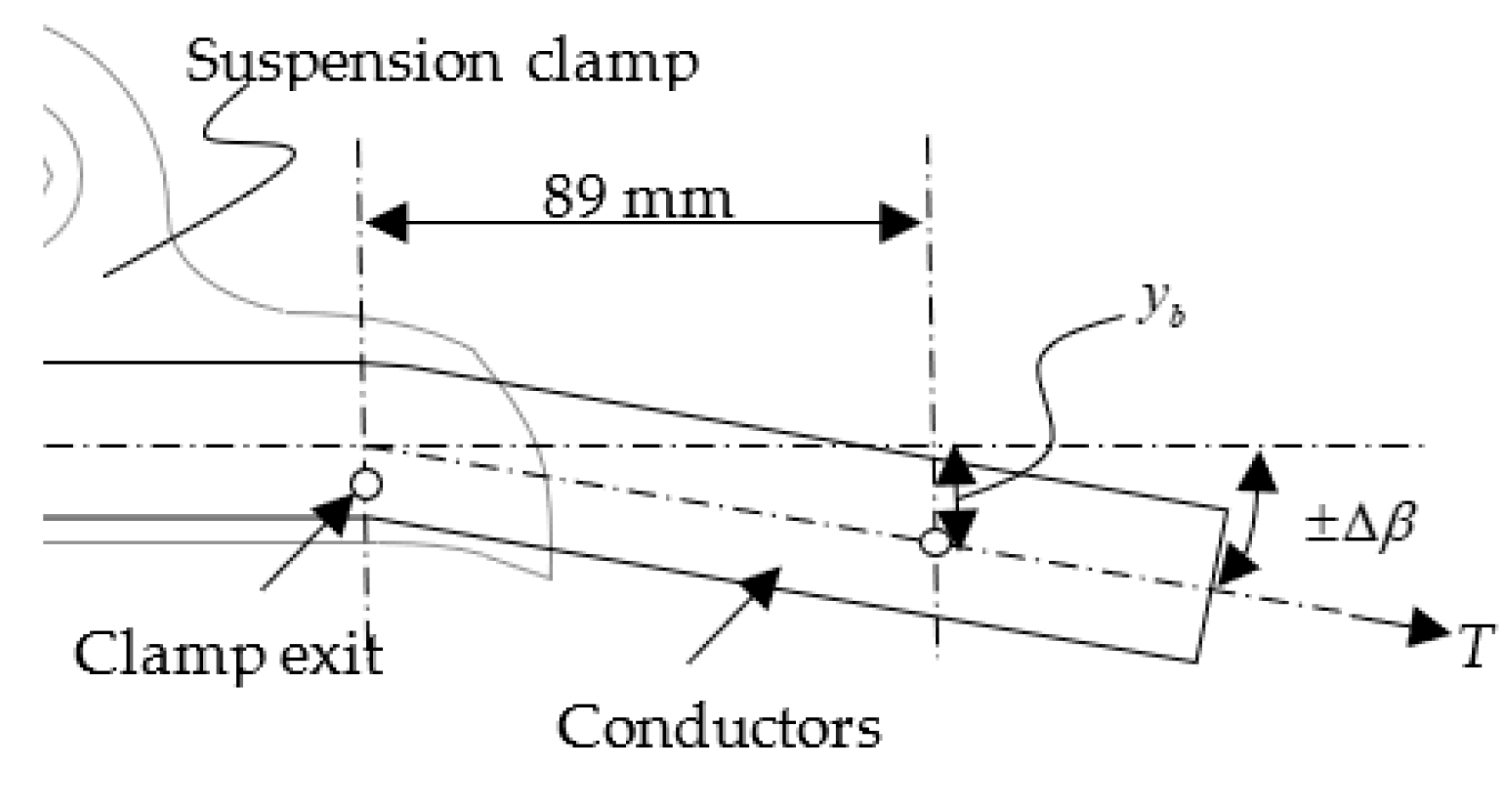
5. Aeolian Vibration and Its Controlling

5.1. Equivalent Lift Force of Vortex-Induced Vibration

Generally, the FE model of the full structure was directly created and assessed for its mechanical behavior. Compared with axial tensile stress, minor bending stress was always ignored in the flexible and long-span cable. Thus, the two-force member, such as the link element without considering bending, was appropriate for modeling overhead transmission lines. As it is similar to conventional cable-supported structures, components of the long-span CRS, including conductors, insulators, cables and connectors, were meshed by a two-node link element. The external wind force was subjected to all nodes of the above components (Figure 20). Wind load effect during VIV was simplified and equivalent to lift force, as the following expression [11]:
F L ( t ) = 1 2 ρ D V 2 C L ( t )
where ρ is air density (kg/m3), V is wind speed (m/s), C L ( t ) is equivalent sectional lift coefficient related to time history t .
The vortex-induced force was expressed as the function of air density, mean wind speed, the diameter of the cross-section and corresponding aerodynamic parameters [22,23]. Assuming that vortex shedding is an essentially sinusoidal process, the sectional lift coefficient was expressed as:
C L ( t ) = 2 C L sin ( 2 π f w t )
where f w is the frequency of vortex shedding (Hz), C L is R.M.S. (root mean square) lift coefficient, which was approximated the calculation as below [24]:
C L = 0.045 + 1.05 × ( 1 Re / 1600 ) 4.5
where Re is the Reynolds number. Experiment data showed that the above formula was available for 260 < Re 1.6 × 10 3 . Within the above range, the Reynolds number was approximately calculated from the Strouhal number, St , Re ( 0.2139 St ) / 4 and St = 0 . 185 in this case [25].
Considering the balance of wind-induced vibration of the structural system, the frequency of vortex shedding ( f w ) was equal to the frequency of structure vibration ( f ). Based on the Strouhal equation, the relationship between vibration frequency and wind speed was expressed as follows:
f = f w = V St D
Energy consumption of the Single Degree-Of-Freedom (SDOF) system with viscous damping under harmonic load ( W ) was expressed as below:
W = o T f d y d t = c A 2 ω 2 0 T cos 2 ( ω t φ ) d t = π c A 2 ω
where A is the vibration amplitude of conductor and A = 2 y max , f d is the damping force, c is the damping coefficient, ω is the circular frequency of harmonic vibration, t is the time (s). During the VIV process, dissipating power of the conductor per length was equivalent to the energy consumption of damping forces. According to Equation (10), energy consumption was expressed as below [26]:
W = P c t Δ l = P c Δ l / f = π c A 2 ω
where P c is the dissipating power of conductor per length, and the dissipating power of conductor per length was evaluated as below (Foti and Martinelli 2018):
P c = 4 π 4 m 2 E I y 2 max f 5 T 2
where T is the tensile force of conductor (N), m is the mass per unit length of conductor (kg/m) and E I is equivalence sectional flexural rigidity of conductor (N·m2).
Thus, damping coefficient c was obtained:
c = 1 2 π 2 m 2 E I f 3 T 2
where E I is sectional flexural rigidity of conductor (N·m2). Accordingly, the self-damping characteristic of the conductor was introduced to the FE model, and thus accurate simulation of VIV of the conductor was achieved by damping coefficient [26].
The relationship between the conductor and suspension cable during vibration was analyzed. Equivalent lift force of VIV was applied on conductors and suspension cables, respectively. Dynamic wind loads were applied to the deformed structure under gravity. Steady vibrating amplitude was defined as the maximum amplitude of the conductor or cable in given frequency vibration.
In order to regulate evaluation and industry practice, the IEEE committee in 1966 proposed the establishment of a conductor vibration intensity from peak-to-peak deflection, measured at 89 mm (3.5 in) from the clamp exit (Figure 21) [8], where y b is the deflection of measure point.
The dynamic bending strain was established as follows [27]:
ε a = D ( T / 4 E I ) e T / E I z 1 + T / E I z y b
where z = 89   mm is the distance from the clamp exit to the amplitude measurement point.

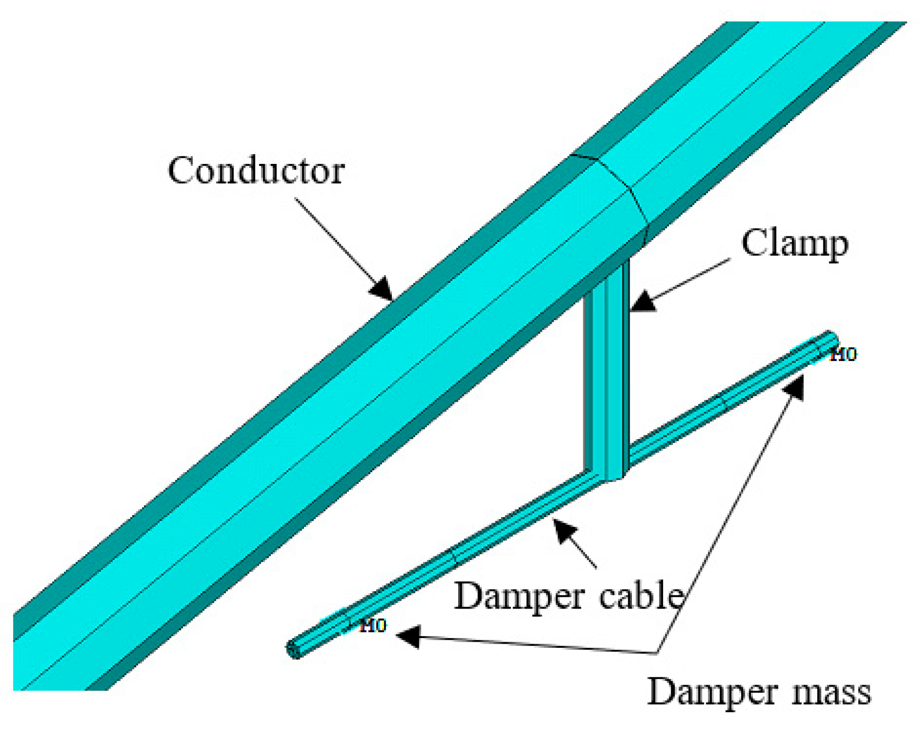
5.2. FE Model of Damper
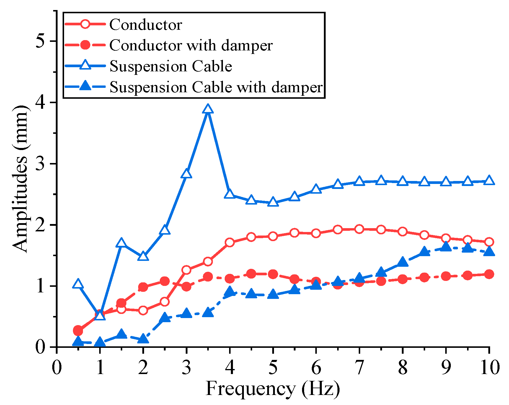
Currently, Stockbridge dampers (FRSD), shown in Figure 22, are one of the most widely used protective equipment for controlling wind-induced vibration in power transmission lines [28]. In the mechanical model, the damper mass and clamp of FRSD were assumed as a rigid body, and the cable was equivalent to an elastic spring. The dynamic characteristics of the damper were considered as equivalent mass and rotary inertia in full FE modeling, as shown in Table 2. FE model of FRSD dampers was modeled by 3D beam element. Concentrated masses adhered to either end of the damper cable. Dampers were fixed connected to the cable and conductor. The detail of the connection between suspension cable, conductor and insulators is shown in Figure 23.

5.3. Result

As described above, the analysis of bending strains of an individual conductor (fixed at both ends) and conductor and cable within the long-span CRS are shown in Figure 24. For the case of the long-span CRS, it is worth noting that its dynamic bending strain of conductor had significant change trends between the individual conductor. The bending strain of the conductor of the CRS increased with frequency in the low-frequency stage and decreased after a peak value, where the frequency was about 7.5 Hz. The reasons for this phenomenon were the source of increasing equivalent lift force and dissipating the power of the conductor with frequency. The equivalent lift force led to an increase in vibration, but dissipating power of the conductor suppressed it. Additionally, the structure feature of CRS limited the effect dissipating the power of the conductor, especially in the low-frequency stage. On the other hand, when VIV occurs in cable, the bending strain approximately increases with frequency except for a peak value of 4 Hz. It was concluded that compared with conductor conventional tower-line system, long-span CRS was more vulnerable because of the larger amplitude of VIV.
Conductor and suspension cables were modeled independently and studied individually. The results of VIV occurred in different parts of long-span CRS were studied. In Figure 25, the distinction between VIV occurred only in the conductor or the cables, and amplitude changes after the damper was installed were shown. Dampers have a limited effect in the low-frequency stage for conductors but a significant effect in almost all frequency stages for suspension cables. Moreover, dampers can effectively clip the peak of amplitude besides reducing the amplitudes of the suspension cable. Figure 26 considered that VIV occurred in both the conductor and suspension cable. Compared with Figure 25, the significant difference is that VIV occurred in cable leads to a faster increase in amplitudes of the conductor in 3~6 Hz but has no effect on the peak amplitude. However, with the increase in frequency, which leads to the dissipating power of the damper increasing, amplitudes of the conductor were significantly reduced.
In summary, the installation of dampers had an effect on the vibration characteristics of a long-span CRS. Additionally, dampers in the conductor and suspension cables significantly reduce amplitudes, and the effect increases with frequency. Accordingly, the installation of dampers on both conductor and suspension cables was effective and essential to protect the structure from the danger of VIV.
The above discussion provided the preliminary basis for the design of protective measures of long-span CRS. Attaching dampers to the conductor and suspension cable was a practical protective measurement regarding VIV of long-span CRS. For suspension cables, the maximum amplitude occurred in a lower frequency band, which needs more attention. For the conductor, the resonance frequency band of the conductor and suspension cable should be of concern because of the larger dynamic bending strain. Moreover, the installation of dampers had an effect on the vibration characteristics of long-span CRS. Accordingly, installing dampers on both conductor and suspension cables was effective and necessary to protect the structure from the danger of VIV.

6. Conclusions

This paper presented a study on the wind-induced response of a long-span cross-rope suspension transmission power line with a tension insulator. The following corresponding conclusions were summarized.
Assembly modeling of long-span CRS is one of the major topics discussed in this paper. Based on the approximate parabola shape function and finite element method, deformed shapes of each substructure by gravity were calculated and assembled into a full structural system;
The increase in wind speed resulted in significant changes in the tensile force and horizontal displacement of the structure. The results showed that horizontal displacement of conductor and tensile force of suspension cable increased with wind speed and number of spans. These results provide the basis for the actual engineering design of wind resistance performance of multi-span CRS;
The increase in ice thickness resulted in an increase in the tensile force of suspension and cable. Moreover, the longer span length of the conductor induced a larger windward projected area of the conductor and thus larger tensile force in the suspension cable. On the other hand, horizontal displacement of the conductor increased firstly and then reduced with ice thickness. The reason for this phenomenon was the combined action of increased wind load and tensile force of conductor induced by ice thickness;
The VIV of long-span CRS and the effect of dampers were studied in the FE model. For the conductor, the increase in amplitude was majorly influenced by the equivalent lift force and dissipating power of the conductor, which led the amplitude to firstly increase and then decrease with frequency. For the cable, amplitude increased with frequency except for a peak value, which is about 3.5 Hz, the resonance frequency band of the conductor and suspension cable. Maximum amplitudes of the conductor and cable decreased when dampers were installed. For the conductor, dampers have a limited effect in the low-frequency stage, but with an increase in frequency, which leads to an increase in the power of the damper dissipating, the amplitudes of the conductor were significantly reduced. For the cable, dampers can effectively clip the peak of the amplitude besides reducing the amplitudes.

Author Contributions

Conceptualization, Z.L. and X.T.; writing—original draft preparation, Y.H.; supervision, Z.L. All authors have read and agreed to the published version of the manuscript.

Funding

This research received no third-party funding.

Institutional Review Board Statement

Not applicable.

Informed Consent Statement

Not applicable.

Data Availability Statement

All data are summarized in the tables.

Acknowledgments

The research presented in this paper was conducted with the support of NSFC-JSPS China-Japan Scientific Cooperation Project (NSFC Grant No. 51611140123). This support is gratefully acknowledged.

Conflicts of Interest

The authors declare no conflict of interest.

References

  1. Brian White, H. Guyed structures for transmission lines. Eng. Struct. 1993, 15, 289–302. [Google Scholar] [CrossRef]
  2. Burger, A.; Serrano, J.D.; Marais, P.; Jacobs, B. Construction of overhead lines in environmentally sensitive areas. Transm. Distrib. 2011, 7, 36–43. [Google Scholar]
  3. Behncke, R.H.; White, H.B. The Cross Rope Suspension Structure. In Electrical Transmission in a New Age; American Society of Civil Engineers: Reston, VA, USA, 2002; pp. 259–267. [Google Scholar] [CrossRef]
  4. Toklu, Y.C.; Bekdaş, G.; Temur, R. Analysis of cable structures through energy minimization. Struct. Eng. Mech. 2017, 62, 749–758. [Google Scholar] [CrossRef]
  5. Jia, Y.; Liu, R. Form-Finding System for Overhead Transmission Line Based on ANSYS. Energy Procedia 2012, 17, 975–982. [Google Scholar] [CrossRef] [Green Version]
  6. Keyhan, H.; McClure, G.; Habashi, W.G. Dynamic analysis of an overhead transmission line subject to gusty wind loading predicted by wind–conductor interaction. Comput. Struct. 2013, 122, 135–144. [Google Scholar] [CrossRef]
  7. Krishnasamy, S.S.G.; Tabatabai, M. Wind loads on bare and ice-covered overhead conductors. J. Wind Eng. Ind. Aerodyn. 1990, 36, 171–180. [Google Scholar] [CrossRef]
  8. Lalonde, S.; Guilbault, R.; Langlois, S. Modeling multilayered wire strands, a strategy based on 3D finite element beam-to-beam contacts–Part II: Application to wind-induced vibration and fatigue analysis of overhead conductors. Int. J. Mech. Sci. 2017, 126, 297–307. [Google Scholar] [CrossRef]
  9. Song, Y.; Zhang, M.; Øiseth, O.; Rønnquist, A. Wind deflection analysis of railway catenary under crosswind based on nonlinear finite element model and wind tunnel test. Mech. Mach. Theory 2022, 168, 104608. [Google Scholar] [CrossRef]
  10. Chen, T.; Huang, Y.-C.; Xu, Z.-W.; Chen, J.C.Y. Wind vibration control of stay cables using an evolutionary algorithm. Wind Struct. 2021, 32, 71–80. [Google Scholar] [CrossRef]
  11. Vecchiarelli, J.; Currie, I.G.; Havard, D.G. Computational Analysis of Aeolian Conductor Vibration with a Stockbridge-Type DAMPER. J. Fluids Struct. 2000, 14, 489–509. [Google Scholar] [CrossRef]
  12. Nie, X.; Yan, Z.; Shi, J.; You, Y. The Refined Simulation and Model Analysis of the Suspension Cable Guyed Tower. J. Shanghai Jiaotong Univ. 2019, 53, 1066–1073. [Google Scholar] [CrossRef]
  13. Tian, L.; Zhou, M.Y.; Qiu, C.X.; Pan, H.Y.; Rong, K.J. Seismic response control of transmission tower-line system using SMA-based TMD. Struct. Eng. Mech. 2020, 74, 129–143. [Google Scholar] [CrossRef]
  14. Vaja, N.K.; Barry, O.R.; Tanbour, E.Y. On the modeling and analysis of a vibration absorber for overhead powerlines with multiple resonant frequencies. Eng. Struct. 2018, 175, 711–720. [Google Scholar] [CrossRef]
  15. Foti, F.; Martinelli, L. A unified analytical model for the self-damping of stranded cables under aeolian vibrations. J. Wind Eng. Ind. Aerodyn. 2018, 176, 225–238. [Google Scholar] [CrossRef]
  16. Foti, F.; Martinelli, L. An enhanced unified model for the self-damping of stranded cables under aeolian vibrations. J. Wind Eng. Ind. Aerodyn. 2018, 182, 72–86. [Google Scholar] [CrossRef]
  17. Fadel, A.A.; Rosa, D.; Murça, L.B.; Fereira, J.L.A.; Araújo, J.A. Effect of high mean tensile stress on the fretting fatigue life of an Ibis steel reinforced aluminium conductor. Int. J. Fatigue 2012, 42, 24–34. [Google Scholar] [CrossRef]
  18. Zhang, M.; Xu, F. Tuned mass damper for self-excited vibration control: Optimization involving nonlinear aeroelastic effect. J. Wind Eng. Ind. Aerodyn. 2022, 220, 104836. [Google Scholar] [CrossRef]
  19. Fujino, Y.; Abé, M. Design formulas for tuned mass dampers based on A perturbation technique. Earthq. Eng. Struct. Dyn. 1993, 22, 833–854. [Google Scholar] [CrossRef]
  20. Tu, X.; Wu, Y.; Li, Z.; Wang, Z. Vortex induced vibration and its controlling of long span Cross-Rope Suspension transmission line with tension insulator. Struct. Eng. Mech. 2021, 78, 87. [Google Scholar]
  21. Yan, Z.; Li, Z.; Savory, E.; Lin, W.E. Galloping of a single iced conductor based on curved-beam theory. J. Wind Eng. Ind. Aerodyn. 2013, 123, 77–87. [Google Scholar] [CrossRef]
  22. Gabbai, R.D.; Benaroya, H. An overview of modeling and experiments of vortex-induced vibration of circular cylinders. J. Sound Vib. 2005, 282, 575–616. [Google Scholar] [CrossRef]
  23. Zhang, M.; Xu, F.; Øiseth, O. Aerodynamic damping models for vortex-induced vibration of a rectangular 4:1 cylinder: Comparison of modeling schemes. J. Wind Eng. Ind. Aerodyn. 2020, 205, 104321. [Google Scholar] [CrossRef]
  24. Norberg, C. Fluctuating lift on a circular cylinder: Review and new measurements. J. Fluids Struct. 2003, 17, 57–96. [Google Scholar] [CrossRef]
  25. Peng, H.; Wang, B.; He, Q.; Zhen, Y.; Wang, Y.; Wen, S. Multi-parametric optimizations for power dissipation characteristics of Stockbridge dampers based on probability distribution of wind speed. Appl. Math. Model. 2019, 69, 533–551. [Google Scholar] [CrossRef]
  26. Kong, D.; Li, L.; Long, X.; Liang, Z. Analysis of aeolian vibration of UHV transmission conductor by finite element method. J. Vib. Shock 2007, 26, 64–67. (In Chinese) [Google Scholar]
  27. Poffenberger, J.C.; Swart, R.L. Differential Displacement and Dynamic Conductor Strain. IEEE Trans. Power Appar. Syst. 1965, 84, 281–289. [Google Scholar] [CrossRef]
  28. Dutkiewicz, M.; Machado, M. Spectral element method in the analysis of vibrations of overhead transmission line in damping environment. Struct. Eng. Mech. 2019, 71, 291–303. [Google Scholar] [CrossRef]
  29. Luo, X.Y.; Zhang, Y.S.; Xie, S.H.; Li, X.C.; Xu, Z.L.; Liu, L.J. Nonlinear impedance tests for a vibration damper and its parametric identification. Zhendong Yu Chongji/J. Vib. Shock 2013, 32, 182–185. [Google Scholar] [CrossRef]
Figure 1. Long-span cross-rope suspension overhead transmission line.
Applsci 12 01488 g001
Figure 2. Diagram of long-span cross-rope suspension line.
Applsci 12 01488 g002
Figure 3. Process of assembly modeling for long-span CRS.
Applsci 12 01488 g003
Figure 4. FE models of long-span cross-rope suspension lines with multi-spans of conductors. (a) Two spans, (b) 3 spans, (c) 4 spans, (d) 5 spans.
Applsci 12 01488 g004
Figure 5. Unscaled deformation of CRS by dead load (Black: undeformed. Blue: deformed). (a) Single span, (b) detail of cross-rope connection.
Applsci 12 01488 g005
Figure 6. Vibration modes and frequencies of single conductor. (a) First symmetric lateral bending (f = 0.080 Hz), (b) Second asymmetric vertical bending (f = 0.160 Hz).
Applsci 12 01488 g006
Figure 7. Frequencies of vibration modes of multi-span CRS.
Applsci 12 01488 g007
Figure 8. First asymmetric vertical bending modes of multi-span CRS. (a) Two spans, (b) 3 spans, (c) 4 spans, (d) 5 spans.
Applsci 12 01488 g008
Figure 9. First symmetric lateral bending modes of multi-span CRS. (a) Two spans, (b) 3 spans, (c) 4 spans, (d) 5 spans.
Applsci 12 01488 g009
Figure 10. First asymmetric lateral bending modes of multi-span CRS. (a) Two spans, (b) 3 spans, (c) 4 spans, (d) 5 spans.
Applsci 12 01488 g010
Figure 11. Diagram of wind loading (in 2 spans).
Applsci 12 01488 g011
Figure 12. Demonstration of cross-section of conductor with ice covering.
Applsci 12 01488 g012
Figure 13. Unscaled deformation of long-span cross-rope suspension line by static wind load. (Dotted: undeformed. Solid: Deformed.)
Applsci 12 01488 g013
Figure 14. The influence of wind speed on tensile force of suspension cable.
Applsci 12 01488 g014
Figure 15. The influence of length of spans of conductor on tensile force of suspension cable (wind speed: 10 m/s).
Applsci 12 01488 g015
Figure 16. The influence of wind speed on maximum horizontal displacement of conductor.
Applsci 12 01488 g016
Figure 17. The influence of wind speed on maximum horizontal displacement of conductor (fixed ice thickness with 10 mm).
Applsci 12 01488 g017
Figure 18. The influence of number of spans of conductor on tensile force of suspension cable (wind speed: 10 m/s).
Applsci 12 01488 g018
Figure 19. The influence of number of spans of conductor on maximum horizontal displacement of conductor (wind speed: 10 m/s).
Applsci 12 01488 g019
Figure 20. Typical wind lift loading mode in FE model of CRS (2 spans). (a) Conductor, (b) cable.
Applsci 12 01488 g020
Figure 21. Standardized conductor dynamic bending amplitude measurement.
Applsci 12 01488 g021
Figure 22. FR-3 Stockbridge damper. (Left: Small damper mass. Right: Big damper mass.)
Applsci 12 01488 g022
Figure 23. Detail of FE model of FRSD damper.
Applsci 12 01488 g023
Figure 24. Bending strains of conductor and cable in 89 mm from clamp exit (wind load applied on conductor and cable).
Applsci 12 01488 g024
Figure 25. Amplitudes of long-span CRS (VIV occurs separately in conductor or cable).
Applsci 12 01488 g025
Figure 26. Amplitudes of long-span CRS (VIV occurs both in conductor and cable).
Applsci 12 01488 g026
Table 1. Recommended design parameters of long-span CRS.
Design ParametersRope for ConductorQuad-Bundle ConductorTension Insulator
Span (m)100080010 in total
Total cross section area (mm2)766.50425.24125,600
External diameter (mm)3626.82400
Weight per length (kg/m)59.521.35100
Elastic modulus (N/mm2)180,00065,000190,000
Table 2. Structure parameters of FRSD.
SubstructuresBig Damper MassSmall Damper Mass
Mass of damper (kg)2.5571.842
Length of damper cable (m)0.2020.145
Center of mass to the junction (m)3.25 × 10−21.21 × 10−2
Rotary inertia (kg·m2)6.51 × 10−33.30 × 10−3
Flexural rigidity of damper cable (N·m2)22.4122.41
Damping ratio of the system [29]0.16
Publisher’s Note: MDPI stays neutral with regard to jurisdictional claims in published maps and institutional affiliations.

