Abstract
The renewed interest in space exploration has led to the growth in research efforts pertaining to advanced space propulsion systems, including highly efficient electric propulsion systems. Although already tested in space many decades ago and being currently employed on various space platforms and thousands of satellites, these systems are yet to reach their full potential for applications on orbit and in deep space. One specific feature of space electric propulsion is the large diversity of physical processes used in this technology, which is not typical for many other types of propulsion systems used in transport, such as those used by airplanes or automobiles. Various physical processes and mechanisms underpin different electric propulsion technologies and should be integrated to drive the future science and technology of space electric propulsion systems. This opinion article briefly highlights this feature of space electric propulsion and outlines some challenges and opportunities that follow from this diversity.
1. Introduction
Current space exploration plans include the deployment of multiple satellite constellations made up of hundreds to several thousands of small orbital assets [1,2,3,4], each capable of being highly active by changing their attitude and orbital parameters. As a result, there is a strong need for advanced space electric propulsion platforms to provide such capabilities [5,6,7]. Furthermore, recently, there has been an increased interest in deep space missions aimed, for instance, at asteroid capture or voyages to Mars. These missions are feasible only with highly efficient means of space electric propulsion that allow for overall spacecraft mass reduction while increasing spacecraft manoeuvrability [8,9,10]. Miniaturized satellites that occupy orbits around the Earth [11,12] also require highly efficient electric propulsion systems, capable of operating on orbit without refuelling [13,14]. Advanced materials and nanofabrication that drive progress in the development of these on-orbit assets, and space technology in general, [15,16,17] will also play an important role in the emergence of permanent stations on the Moon and Mars, which are closer to their realisation than ever [18,19,20]. These lighter, more durable systems, possibly featuring self-healing [21,22] and self-restoration abilities [15], will be less costly to deliver to and maintain at these distant outposts, with the outposts themselves serving as hubs from which smaller space assets can be managed and deployed.
The aim of this Opinion article is not to provide a comprehensive review of the current state of the art for modern space propulsion systems, though interested readers are directed to the most recent reviews where electric propulsion systems, including their operating principles for various types of propulsion platforms and their key characteristics, are discussed in significant depth [5,23,24,25,26]. Instead, the core objective of this article is to emphasize the importance of such features of space electric propulsion systems as:
- ✓
- The wide diversity of physical processes and effects involved in space electric propulsion technologies, and
- ✓
- The amenability of these systems to miniaturization and implementation of cutting-edge materials for the advancement of gridded ion thrusters, Hall-type thrusters, magnetoplasmadynamic (MPD) accelerators, Rotamak-type platforms, electrospray systems and other promising propulsion platforms [27,28,29].
The improvement in the performance of these systems relies on the ongoing development of the specific sub-systems, e.g., highly efficient cathodes [30,31,32], as well as on the use of complex modelling approaches [33] and unique test equipment [34] to probe the physical processes that govern their performance.
Thus, the ultimate aim of this article is to introduce the reader to some of the challenges and opportunities for the development of future space electric propulsion systems in the context of the diversity and complexity of physical processes that underpin their operation (Figure 1).
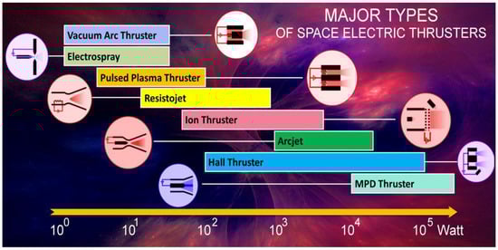
Figure 1.
The major types of space electric propulsion thrusters spanning the input power to the thruster. The circled icons represent the basic electrical schematics of each type of thruster. This image illustrates the wide spread of physical complexity that is manifested by the numerous propulsion devices employed over five orders of magnitude of power to the thruster.
2. Variety of Physical Processes to Integrate into a Single Design
Novel physical principles are now being explored to create thrust in space [35,36], along with intense research efforts to further advance the existing types of space thrusters [23,24,25,26,27,28,29,30,31,32,33,34,35,36,37,38,39]. The pace propulsion systems illustrated in Figure 1 using plasma [40,41,42,43] and ion jets [30,31,32,33,34,35,36,37,38,39,40,41,42,43,44,45,46,47] are among the most promising systems due to numerous advantages [48,49,50], including high specific impulse [51,52] and long service life [53,54] in space. Currently, space technology, and in particular space electric propulsion systems are undergoing rapid development as part of many advanced space programs [55], including NASA’s Mars and Moon exploration programs [56] which will require high-powered electric propulsion systems [57,58], and a large number of deep space exploration projects [59,60]. Table 1 lists several key parameters (including efficiency and operational time) for the major types of space electric propulsion technologies. However, despite many exciting and promising developments, we are yet to realise propulsion systems that would provide these missions with the necessary level of efficiency, reliability and lifetime [61]. This is particularly true for miniaturised thrust-generating systems that need to deliver a sufficiently high level of performance under stringent power, mass and volume constraints. These constraints also apply to the supporting sub-systems (e.g., propellant and energy storage), which are only allowed to take up limited space within the satellite.

Table 1.
Principal characteristics of the main EP thruster types (see detailed description in the comprehensive review [24]). Reproduced from [24] under the terms and conditions of CC BY license. Copyright 2020, Authors. Nomenclature: GIE—gridded ion engine; HET—Hall effect thruster; HEMPT—high efficiency multistage plasma thruster; PPT—pulsed plasma thruster; MPDT—magnetoplasmadynamic thruster; ECR—electron cyclotron resonance; PPU—power processing unit. The electrical efficiency of the thrusters was calculated as the ratio of jet power to the total input electric power to the thruster. A contribution of chemical energy from the propellant and/or energy from pressurised gas was not taken into account, thus numbers exceeding 100% could be obtained.
When compared to conventional thermochemical thrust systems, electric propulsion platforms feature a substantially increased specific impulse, i.e., exhaust velocity of propellant. There is a growing demand for exclusively electrically powered, all-electric satellites [62,63], with both industry and Universities allocating significant funds and efforts to increase the efficiency and reliability of electrostatic and electrodynamic thrusters [64] and associated ancillary sub-systems. These include cathodes for plasma generation and neutralisation [31], control systems, propellant feed and storage systems [65] and the materials from which these systems are made [15].
There is also a significant overlap with research efforts that exploit the physical and chemical processes generated in plasmas to fabricate and assemble materials [66] and devices [67,68,69,70,71,72] for space technologies, as well as for other applications [73,74,75,76,77]. This means that the modifications of, for example, Hall-type thrusters can be used for the synthesis of materials and even for the growth of materials directly in the thruster channel (e.g., nanodiamonds, graphene flakes and others, see details in [78]). A comparison with currently available propulsion technologies, both well-developed (e.g., chemical rockets) and emerging ones (e.g., solar sails), suggests that at present, plasma thrusters represent one of the most practical and technologically realizable means of propulsion for missions requiring high specific impulse, delivered total impulse, thrust precision, and spacecraft control authority. These are the missions that currently drive the exploration and exploitation of near-Earth space and deep space and, eventually, will drive the creation of permanent extra-terrestrial outposts.
Figure 1 exemplifies the wide spread of physical complexity that is manifested by the numerous propulsion devices employed over five orders of magnitude of power to the thruster.
Moreover, even within the same type of thruster technology, a wide spread of the parameters can be observed, e.g., a large collection of experimental material has been accumulated on anode efficiency, which is one of the most important characteristics of the Hall-type space thrusters [79]. A wide spread of the characteristics for the same type of thrusters is an apparent signature of the complexity of the processes, their intertwined characteristics and their mutual interference.
Among the schematics shown in Figure 1, two types of thrusters are the most developed with respect to current application in space: Hall thrusters and ion thrusters, shown in Figure 2 and Figure 3, respectively. These thrusters rely on different acceleration processes, each suitable for a particular range of available electric power.
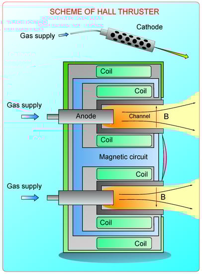
Figure 2.
Various types of space electric propulsion systems utilize a vast variety of interdependent physical processes and design solutions. As an example, the electrostatic system is illustrated: Hall thrusters are among the major candidates for powering future spacecraft. Integration of electric propulsion thrusters into satellites represents an even more complex task due to the possible interactions of the thruster and plasma jets with sub-systems integrated within the satellite. For more details about the operation principles of Hall thrusters, see e.g. [23,24].
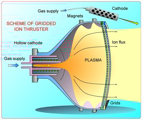
Figure 3.
Gridded ion thruster. The gridded ion thruster is a second promising candidate for powering future spacecraft. Integration of electric propulsion thrusters into satellites represents an even more complex task due to the possible interactions of the thruster and plasma jets with sub-systems integrated within the satellite.
Not surprisingly, a small variation in the design, operational modes, materials and geometry of the thruster results in a dramatic change in its efficiency. On the other hand, optimization of electric and plasma thrusters implies the multi-parametrical optimization of a large number of electric, magnetic, thermodynamic and other concatenated processes.
As a consequence, optimization of space thrusters is considered to be one of the most time-, labour-, and fund-consuming stages of the design. The optimization of parameters of the existing types of thrusters is the first challenge in space electric propulsion.
While optimization challenges need to be solved to improve the characteristics of existing types of engines, the development of new types of thrusters is always a current demand. The necessity to simplify the thruster design to lower power consumption, remove plasma-contaminating elements, improve the performance characteristics and decrease the mass of the device are among the leading incentives for the development. This process follows a well-known routine, where a scrupulous analysis of the design and operational principles of the most developed subject-related engineering solutions results in synthesis of a new device.
One of the promising approaches is the transition from stationary flows and electric/magnetic fields, which are features of Hall and gridded ion thrusters, to rotational configurations.
Several types of electromagnetic plasma thrusters were recently developed by various research groups [80,81,82]. One of the characteristic examples of the rotational system (which is yet quite far from space testing) is the miniaturized Rotamak-type device, which was initially suggested for the experiments with hot plasma for thermonuclear fusion [83].
A rotating magnetic field (RMF) is engaged to drive the azimuthal plasma current in a plasma torus, which is sustained in equilibrium by a steady axial field, applied externally as RMF. A schematic of the setup is shown in Figure 4. An external antenna generates oscillating electric fields to produce plasma. Unlike the common ICP discharge, where the external oscillating field does not penetrate into the plasma because of the plasma’s high conductivity, the implementation of RMF allows the introduction of the external electric field into the Rotamak plasma. In this case, a synchronous rotation of plasma electrons occurs, while ions form a static background of positive charge, creating a shield. In the device, the ponderomotive force accelerates the plasma particles in the same direction, unlike the ion or Hall thrusters, and the field of the force is created by a static magnetic and non-uniform high frequency field.
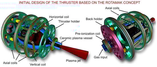
Figure 4.
Initial design scheme of the practical thruster based on the Rotamak concept (under development). The design consists of three axial coils and two holders joined with cross-plates to form the main frame, where the plasma vessel is installed. Additional coils, together with gas supply pipes and insulating inserts, are fixed within the frame. Reprinted with permission from Ref. [83]. Copyright 2021, IOP.
The design features the advantages of the electrodeless thrusters for plasma propulsion, such as: (i) thrust density and acceleration are not limited by Hall parameters or electrical screening; (ii) there is an absence of neutralizer; (iii) the thruster can be throttled between the higher thrust and specific impulse at the constant power; (iv) the electrode erosion and plasma contamination are absent.
Integration of several complex physical processes in a single system enabled the new generation of space thrusters of Rotamak type. This approach could be promising for other efforts on integration of various physical mechanisms to design novel space thruster systems.
One of the big challenges in the modern propulsion industry is miniaturization, which means the development of small thrusters suitable to be employed in the booming market of CubeSats. Indeed, miniaturized plasma thrusters are often considered a propulsion means of choice for small space assets, e.g., small satellites and CubeSats. Yet, a thruster designed for a satellite with centimetre to tens of centimetres dimensions would experience significant power losses in ultra-miniaturized plasma sources, and for this reason cannot provide the desired level of efficiency. Currently, there are active research efforts to combat this issue, with some of the potential solutions outlined [23,61]. Unfortunately, the direct approach of scaling down the well-proven Hall and ion thrusters does not lead to a satisfactory result, since the ratio of the plasma-generating volume (~r3) to the plasma-decay surface (~r2) decreases with a decrease in the thruster size, which leads to a drop in performance characteristics. It should be mentioned that the characteristics of the Rotamak-type setup allow it to be considered for application as a small space thruster. In general, the development of new types of miniaturised plasma thrusters to meet the current requirements of space exploration missions is the challenge. Nowadays, miniaturization of the thrusters is still much in demand.
Vacuum arc thrusters [84,85] are another good example of the conversion of a device initially developed for initiation of arc discharge in technological setups [86,87]. The arc systems vary in design and type of mass supply (via material ablation or using gas supply) and they are relatively simple devices when compared to other thruster types [88]. The device basically consists of two electrodes. The arc discharge is sustained between these two electrodes to produce the plasma out of electrode material and accelerate it within the same discharge. Despite the simplicity, they are still among the promising candidates for powerful thrust systems capable of powering large spacecraft needed for large-scale exploration of remote planets, and possibly Mars colonization, due to their relatively high impulse and ability to produce high levels of thrust (see Figure 1).
However, design simplicity does not necessarily imply the simplicity of the involved physical and chemical processes. Even in such a simplest design, the wide variety of intertangled processes should be integrated.
Due to its design simplicity, the vacuum arc thruster is a good illustration of the complexity of problems that can emerge even in such small plasma setups (Figure 5 and Figure 6). The first problem is arc discharge ignition, which is far from being solved despite many years of development and a very simple design. Currently, at least three main schematics have been proposed to trigger the discharge. These include independent triggering [89], resistance triggering [90], and triggerless schematic [91]. The first two methods rely on an auxiliary pulse generator, and a resistor included into a circuit of a trigger electrode [92], respectively. For the independent triggering, the device includes an annular trigger electrode mounted around a thin cathode and an anode of metal grid with somewhat larger aperture.
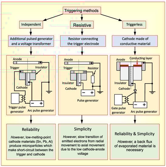
Figure 5.
Triggering methods for various types of arc plasma sources, for potential application in space propulsion systems. This scheme illustrates only one aspect of plasma generation in arc plasma sources, while the operation of thrusters producing an accelerated plasma jet involves a wide variety of the intertangled processes, including processes of ion acceleration and other key factors that underpin thruster physics. Reproduced with permission from Ref. [26]. Copyright 2019, Springer-Nature.
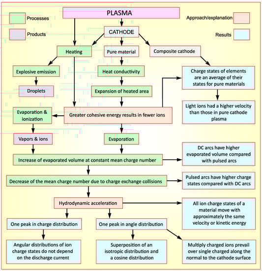
Figure 6.
Schematic describing the ablation and ion charge states distribution. For a very simple design of an arc thruster, the whole set of involved physical processes is quite complex. Reproduced with permission from Ref. [26]. Copyright 2019, Springer-Nature.
For the resistance triggering, the voltage between the cathode and anode should be relatively low, thus leading to the generation of a much weaker axial electric field, as compared to the independent triggering, so the transition from the radial to axial expansion of the flux of plasma electrons is relatively slow. Moreover, the independent triggering ignites more symmetric discharge with respect to the setup axis of symmetry. The last method, i.e., triggerless, was initially proposed for the vacuum arc deposition setups, where a part of the material evaporated in the arc discharge is deposited on a surface of the igniting electrode, namely in the gap between the cathode and anode [91]. At the next ignition cycle, the deposited layer is heated resistively, and evaporates at the electrical breakdown of the gap.
To analyse this problem, readers are encouraged to examine a general schematic of a wide variety of the intertangled processes that reflects only a limited number of aspects of plasma generation, without taking into account processes involved in ion acceleration and other key factors that underpin these thrusters [26]. When compared to these physically simple direct current systems, thrusters that feature more complex physics (such as Hall-type, radio-frequency etc. systems) involve a much more complex hierarchy of physical processes [49,51].
However, ignition of the discharge is only the first stage of the complex chain of physical processes for such a simple design. The whole chain of physical processes is much more complex—see Figure 5 which illustrates two main stages, yet not the whole set of processes.
The second stage is plasma plume formation and control of ion energies. Traditionally, in the setups of vacuum arc technology an axisymmetric magnetic field was applied to form the shape of the extracted ion flux [93,94], and the idea was adopted in VACs [95]. The composite cathodes made as alloys of heavy and light metals, allow the expansion of the set of options with respect to the plasma plume. The non-uniformity in the chemical composition causes the re-distribution in the discharge, when the heavier ions concentrate on the discharge axis of the angular distribution, and the lighter ions gain more kinetic energy in comparison with the pure metal cathodes. At the same time, a pulsed mode of electric supply was considered as the best way to obtain the multiple charged ion flux after a number of experiments [96]. The ways to affect the ablation and ion charge states distribution are summarized in Figure 6.
Apparently, the characteristics of the material flows emitted from the cathode of the arc discharge describe the performance of this type of arc thruster. Vapours, multi-charged ions, neutrals, solid clusters and liquid droplets usually compose the material flux [97,98], and the cathode erosion rate is considered as the primary parameter describing the arc effectivity with respect to the production purposes (either in space propulsion or coating deposition) [99,100]. Despite the long history of investigation of the erosion rates for a large variety of the applied materials and discharge currents, the theoretical background is still not completely clear due to the explosive character of the event [101,102], unlike the evaporation from a steady source [103]. Currently, kinetic models [104] show good agreement with the experimental results.
Hence, one of the most significant challenges in advanced space propulsion technology is the complexity of physical and chemical processes, and the necessity to integrate them into a single highly efficient system.
3. Physical Processes and Metamaterials: New Horizons for Space Propulsion
Synthesis of novel materials for the aerospace industry has always been a challenge since the properties of the materials greatly affect a device’s operation. Indeed, high energy fluxes of particles, high temperatures, the aggressive environment of other planets, dusty particles and so on can affect the surfaces of spacecraft. As a results, cracks, dents and other discontinuities in the material structure occur, thus causing device failure. Similarly, in plasma propulsion devices, erosion of structure elements is the critical factor that greatly affects the thruster’s lifetime. Since the material should withstand external forces, its function can be described as passive. However, there is another group of materials that play a very important role in the space industry in general, and in plasma thrusters in particular. These are active functional materials such as those used in emitters of cathode-neutralizers to produce an electron flux, or magnetic materials used to generate magnetic fields. As in the development of thruster design, newly adopted technical solutions are employed in this domain.
Metamaterials represent a new class of functional materials that could boost space propulsion in various ways. However, the application of metamaterials also requires the integration of a complex set of physical processes.
For the interaction with cold plasma when the electron temperature does not exceed a few tens of electron-volts, three possibilities can be considered to boost space propulsion technologies via advanced metamaterials (Figure 7). Several possible approaches to this are illustrated in Figure 8. The first way depends on the large diversity of plasma species, their mobility, their extraordinal chemical activity and their flexibility towards the control means. Due to its ability to be guided by pressure gradients, friction forces, and electric and magnetic fields, plasma is a perfect tool to modify materials through sputtering, etching and other ballistic and thermal effects. As a result, complex hierarchical micro- and nanostructures are synthesised on various substrates, thus forming a unique platform for future applications [67,105]. The second possible application arises due to the effect of the generation of patterned spatial distributions of electromagnetic fields and charged particles, thus creating the complex plasma structures that can be implemented in space propulsion. For example, metamaterial composed of split ring resonators (SRR) produces shifted SRR resonance when interacting with low-pressure argon plasma [106].
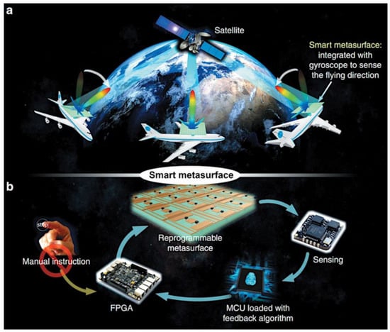
Figure 7.
(a,b) Smart metamaterials may be used for various aerospace technology and many other applications. Reprinted from Ref. [107] under terms and conditions of CC BY License. Copyright 2019, the Authors.
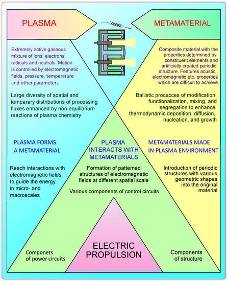
Figure 8.
Plasmas and metamaterials: interrelated processes and properties create new capabilities. Different pathways are possible to enhance the characteristics of space propulsion systems via metamaterial-inspired technologies. Plasma can be used directly to create the novel metamaterials for space applications; plasma can interact with metamaterials to produce novel effects, e.g., a type of virtual antenna; and plasma itself could be a type of metamaterial.
The third application arises from the cases when plasma itself behaves like a metamaterial [108]. There are several examples: An extraordinary wave transition is obtained by the combination of a metamaterial with negative permeability and a plasma array [109]; broadband reduction of a radar cross-section (RCS) is produced by implementation of a combined coating of metamaterial and plasma [110]; and a frequency selective filter can be designed using plasma generated between coupled dielectric resonators (DRs) [111]. Illumination of the single-layer metamaterial by microwave (MW) pulses produces effects that are potentially useful in the development of high-power MW systems [112]. Several comprehensive review articles outline the physics and applications of plasma when it takes on the role of a metamaterial [113]. For example, the featherlight plasma horn antenna could be considered as a system with metamaterial properties [114]. Plasma acting as a metamaterial could be used as a non-linear media for cloaking, for example. [115]. In this system, a set of thin metallic wires generates the plasma that produces a radiation very similar to that produced by the metallic horn.
Miniaturisation could also be discussed from the point of view of emerging and advanced engineering materials that are playing an increasingly important role in driving the progress of space technologies [2,15]. Progress in material science is particularly relevant for the development of more efficient and functional space assets of the CubeSat standard, where these have transformed from relatively simple single-function systems to systems with increased complexity and functionality needed for more advanced space exploration missions [116].
Of particular interest are materials that display complex functionality, adaptivity and self-driven behaviour, such as self-cleaning and self-healing.
The metamaterials, along with the materials that arise from their unique structure and can increase device efficiency [117,118], comprise hierarchically organized physical elements that span multiple scales [119,120]. Some of these features have already been realized, with reported significant improvements in material lifetime and performance, whereas the possibility of self-healing in materials used for thrusters is still at the concept stage and would require significant effort and investment before it can be realized practically.
Metamaterials are likely to find applications across all facets of space propulsion technology [15,23], and more broadly, space exploration technologies. However, the process of plasma interaction with metamaterials is very complex, and special tools and instruments need to be developed to implement this technique in future space propulsion systems.
An interesting example of a hierarchical hybrid system that involves novel materials and advanced design is a small Hall thruster with a hybrid magnetic system consisting of permanent magnets and magnetic coils (Figure 9).
For this design, the samarium–cobalt permanent magnets were tested. Samarium–cobalt magnets are applied in various branches of industry, e.g., in the computer numerical control units or magnetron heads of DC motors [121], because the magnets produce strong magnetic fields at a relatively small size. At the same time, magnetic fields are an essential feature of plasma thrusters such as Hall and arc thrusters, and the configuration and strength of the field is critical for the performance of the thrusters. For thruster operation, the strength varies in the range of a few mT to a few T (for arc thrusters in pulsed mode). Obviously, the need for flexible control of thruster operation promotes the application of electromagnets, where the direction and strength of the magnetic field can be varied by simply changing the terminals of the power source and the direction of the current passing through the coils of the electromagnet.
Unfortunately, electromagnets undergo extensive heating with the increase of the coil current, which is the reason a magnetic field of 1 T is necessary to operate a miniaturized arc thruster can only be obtained in the pulse mode. Additionally, electromagnets significantly increase the weight of the device, and require a power supply. Thus, due to the large range of the applied magnetic field and the necessity of flexible operation of the thrusters, a combination of permanent magnets that are able to generate a strong but constant magnetic field, and electromagnets that can adjust the magnetic field strength, is considered. Figure 7a presents a schematic of a typical Hall-type thruster, while a hybrid magnetic system [122] of a small Hall thruster (23 mm diameter) is shown in Figure 7b. As can be seen, the permanent magnets are engaged to ensure the principal magnetization, while the electromagnetic part serves to adjust the magnetic field to the specified parameters.

Figure 9.
(a) Magnetic circuit (shown in yellow) in the typical Hall-type thruster. (b) Hybrid magnetic system of a small Hall thruster, which incorporates coils that can be connected in the straight and reverse directions, and a set of 24 to 50 samarium–cobalt permanent magnets. The permanent magnets are necessary for principal magnetization, while the turns ensure flexible control of the resulting magnetic field. Reproduced with permission from Ref. [122]. Copyright 2018, IEEE.

Another example of the implementation of a traditional technology to increase the lifetime of a miniature micronewton arc thruster is deposition of boron-containing coatings, which prevents the degradation of the interelectrode film that occurs after numerous arc pulses and increases the lifetime by a factor of 6–17 [123].
While the implementation of samarium–cobalt permanent magnets in space propulsion is a novel application of a well-known material, metamaterials present the next step in the development of new materials to overcome the limitations intrinsic to the traditional materials in aerospace technologies. As was found in a number of experiments, many effects which can be useful for space propulsion occur at the interaction of plasma with metamaterials [124].
4. Concluding Remarks
Space electric propulsion systems, in contrast to other electric transportation techniques that are usually represented by only a few types of propulsors, feature a very wide diversity of thrusters that operate on the basis of vary different—and quite complex—physical processes. Moreover, space thrusters routinely involve a long chain of intricate, intertangled processes. As a result, the integration and optimization of such thrusters, owing to the complexity of their physics, is a very difficult problem that is still under extensive exploration. On the other hand, this diversity offers new perspectives for the further development of space electric propulsion technology.
In this article we stressed these two aspects, pointing out that to overcome the complexity and intertangled character of the processes in thrusters, new tools and instruments need to be developed, including numerical methods for the complex systems that cannot be tested directly in labs, and novel plasma characterization systems including automated robotized test facilities that allow for fast collection of big data. On the other hand, the integration of several physical mechanisms could result in the designing of novel, advanced space propulsion systems with excellent characteristics. Such systems are vitally needed for upcoming space missions, including Mars and Moon exploration and advanced outer space scientific missions.
Author Contributions
Conceptualization, I.L., O.B. and K.B.; writing—original draft preparation, I.L., O.B., D.P., S.X., D.L., K.B.; writing—review and editing, I.L., O.B., D.P., C.R., H.E.R., S.X., D.L., K.B. All authors have read and agreed to the published version of the manuscript.
Funding
This work was jointly supported by the Plasma Sources and Application Centre, NIE, Nanyang Technological University, Singapore; and the National Research Foundation and AcRF (Rp6/16 Xs), Singapore. K.B. acknowledges the funding from the Australian Research Council (DE130101550, DP180101254). O.B. acknowledges the funding from the National Research Foundation of Ukraine under grant agreement No. 2020.02/0119.
Acknowledgments
I.L. acknowledges the support from the NIE, Nanyang Technological University, Singapore.
Conflicts of Interest
The authors declare no conflict of interest.
References
- Levchenko, I.; Keidar, M.; Cantrell, J.; Wu, Y.-L.; Kuninaka, H.; Bazaka, K.; Xu, S. Explore space using swarms of tiny satellites. Nature 2018, 562, 185. [Google Scholar] [CrossRef]
- Swartwout, M. The First One Hundred Cubesats: A Statistical look. J. Small Satell. 2013, 2, 213–233. [Google Scholar]
- Levchenko, I.; Xu, S.; Wu, Y.; Bazaka, K. Hopes and concerns for astronomy of satellite constellations. Nat. Astron. 2020, 4, 1012–1014. [Google Scholar] [CrossRef]
- Aglietti, G.S. Current challenges and opportunities for space technologies. Front. Space Technol. 2020, 1, 1. [Google Scholar] [CrossRef]
- Levchenko, I.; Goebel, D.M.; Bazaka, K. Electric propulsion of spacecraft. Phys. Today 2022, 75, 38. [Google Scholar] [CrossRef]
- Calvo, E.M.; Pinheiro, M.J.; Sá, P.A. Modeling of electrohydrodynamic (EHD) plasma thrusters: Optimization of physical and geometrical parameters. Appl. Sci. 2022, 12, 1637. [Google Scholar] [CrossRef]
- Cardillo, E.; Cananzi, R.; Vita, P.; Caddemi, A. Dual-conversion microwave down converter for nanosatellite electronic warfare systems. Appl. Sci. 2022, 12, 1524. [Google Scholar] [CrossRef]
- Atchison, J.A.; Hibbard, K.E.; Kantsiper, B.L.; Reed, C.L.B.; Rivkin, A.S. Asteroid Impact and Deflection Assessment: Double Asteroid Redirection Test. In Proceedings of the 68th International Astronautical Congress, Adelaide, Australia, 25–29 September 2017. [Google Scholar]
- Herman, D.; Tofil, T.; Santiago, W.; Kamhawi, H.; Mcguire, M.; Polk, J.E.; Snyder, J.S.; Hofer, R.; Picha, F.; Jackson, J.; et al. Overview of the Development and Mission Application of the Advanced Electric Propulsion System (Aeps). In Proceedings of the 35th International Electric Propulsion Conference (IEPC), Atlanta, GA, USA, 8–12 October 2017. [Google Scholar]
- Díaz, F.C.; Carr, J.; Johnson, L.; Johnson, W.; Genta, G.; Maffionec, P.F. Solar Electric Propulsion for Human Mars Missions. Acta Astronaut. 2019, 160, 183–194. [Google Scholar] [CrossRef]
- Tysiąc, P.; Strelets, T.; Tuszyńska, W. The application of satellite image analysis in oil spill detection. Appl. Sci. 2022, 12, 4016. [Google Scholar] [CrossRef]
- Montisci, A.; Porcu, M.C. A satellite data mining approach based on self-organized maps for the early warning of ground settlements in urban areas. Appl. Sci. 2022, 12, 2679. [Google Scholar] [CrossRef]
- Hammond, T.G.; Allen, P.L.; Wells, H.W.; Russick, J.M.; Nislow, C.; Giaever, G.; Birdsall, H.H. Moonshot: Affordable, simple, flight hardware for the Artemis-1 mission and beyond. Front. Space Technol. 2020, 1, 593523. [Google Scholar] [CrossRef]
- de Carvalho, R.A.; Estela, J.; Langer, M. (Eds.) Nanosatellites: Space and Ground Technologies, Operations and Economics; John Wiley & Sons Ltd.: Hoboken, NJ, USA, 2020. [Google Scholar] [CrossRef]
- Levchenko, I.; Bazaka, K.; Belmonte, T.; Keidar, M.; Xu, S. Advanced materials for next generation spacecraft. Adv. Mater. 2018, 30, 1802201. [Google Scholar] [CrossRef] [PubMed]
- Levchenko, I.; Baranov, O.; Fang, J.; Cherkun, O.; Xu, S.; Bazaka, K. Focusing plasma jets to achieve high current density: Feasibility and opportunities for applications in debris removal and space exploration. Aerosp. Sci. Technol. 2020, 108, 106343. [Google Scholar] [CrossRef]
- Baranov, O.; Košiček, M.; Filipič, G.; Cvelbar, U. A deterministic approach to the thermal synthesis and growth of 1D metal oxide nanostructures. Appl. Surf. Sci. 2021, 566, 150619. [Google Scholar] [CrossRef]
- Musk, E. Making Humans a multi-planetary species. New Space 2017, 5, 46–61. [Google Scholar] [CrossRef]
- Do, S.; Owens, A.; Ho, K.; Schreiner, S.; deWeck, O. An independent assessment of the technical feasibility of the Mars one mission plan—Updated analysis. Acta Astronaut. 2016, 120, 192–228. [Google Scholar] [CrossRef]
- Levchenko, I.; Xu, S.; Mazouffre, S.; Keidar, M.; Bazaka, K. Mars colonization: Beyond Getting there. Glob. Chall. 2019, 3, 1800062. [Google Scholar] [CrossRef]
- Kadam, S.; Chavan, S.; Kanu, N.J. An insight into advance self-healing composites. Mater. Res. Express 2021, 8, 052001. [Google Scholar] [CrossRef]
- Nakao, W.; Osada, T.; Nishiwaki, T.; Otsuka, H. Focus on self-healing materials: Recent challenges and innovations. Sci. Technol. Adv. Mater. 2020, 22, 234. [Google Scholar] [CrossRef]
- Levchenko, I.; Bazaka, K.; Ding, Y.; Raitses, Y.; Mazouffre, S.; Henning, T.; Klar, P.J.; Shinohara, S.; Schein, J.; Garrigues, L.; et al. Space micropropulsion systems for Cubesats and small satellites: From proximate targets to furthermost frontiers. Appl. Phys. Rev. 2018, 5, 011104. [Google Scholar] [CrossRef]
- Holste, K.; Dietz, P.; Scharmann, S.; Keil, K.; Henning, T.; Zschätzsch, D.; Reitemeyer, M.; Nauschütt, B.; Kiefer, F.; Kunze, F.; et al. Ion thrusters for electric propulsion: Scientific issues developing a niche technology into a game changer. Rev. Sci. Instrum. 2020, 91, 061101. [Google Scholar] [CrossRef] [PubMed]
- Levchenko, I.; Xu, S.; Mazouffre, S.; Lev, D.; Pedrini, D.; Goebel, D.; Garrigues, L.; Taccogna, F.; Bazaka, K. Perspectives, frontiers, and new horizons for plasma-based space electric propulsion. Phys. Plasmas 2020, 27, 020601. [Google Scholar] [CrossRef]
- Baranov, O.; Levchenko, I.; Xu, S.; Wang, X.G.; Zhou, H.P.; Bazaka, K. Direct current arc plasma thrusters for space applications: Basic physics, design and perspectives. Rev. Mod. Plasma Phys. 2019, 3, 7. [Google Scholar] [CrossRef]
- Jiménez, P.; Merino, M.; Ahedo, E. Wave propagation and absorption in a helicon plasma thruster and its plume. Plasma Sources Sci. Technol. 2022, 31, 045009. [Google Scholar] [CrossRef]
- Wang, Y.; Ren, L.; Ding, W.; Sun, A. Plasma plume evolution of a capillary discharge based pulsed plasma thruster: An optical diagnosis study. Phys. Plasmas 2021, 28, 123509. [Google Scholar] [CrossRef]
- Zhang, Z.; Schäfer, F.; Zhang, G.; Tang, H.; Yeong, W.; Ling, L.; Herdrich, G.; York, T.M. Investigation on operational stability of a pulsed plasma thruster with a pressure probe. Acta Astronaut. 2022, 197, 60–68. [Google Scholar] [CrossRef]
- Pedrini, D.; Misuri, T.; Paganucci, F.; Andrenucci, M. Development of Hollow Cathodes for Space Electric Propulsion at Sitael. Aerospace 2017, 4, 26. [Google Scholar] [CrossRef]
- Gao, Y.; Wang, W.; Xue, S.; Li, Y.; Cai, G. Influence of the upstream axial magnetic mirror field on the plume characteristics in the full cylindrical Hall thruster. Acta Astronaut. 2022, 196, 186–193. [Google Scholar] [CrossRef]
- Lev, D.R.; Mikellides, I.G.; Pedrini, D.; Goebel, D.M.; Jorns, B.A.; McDonald, M.S. Recent progress in research and development of hollow cathodes for electric propulsion. Rev. Mod. Plasma Phys. 2019, 3, 6. [Google Scholar] [CrossRef]
- Kahnfeld, D.; Duras, J.; Matthias, P.; Kemnitz, S.; Arlinghaus, P.; Bandelow, G.; Matyash, K.; Koch, N.; Schneider, R. Numerical modeling of high efficiency multistage plasma thrusters for space applications. Rev. Mod. Plasma Phys. 2019, 3, 11. [Google Scholar] [CrossRef]
- Lim, J.W.M.; Huang, S.Y.; Xu, L.; Yee, J.S.; Sim, R.Z.; Zhang, Z.L.; Levchenko, I.; Xu, S. Automated integrated robotic systems for diagnostics and test of electric and micropropulsion thrusters. IEEE Trans. Plasma Sci. 2018, 46, 345–353. [Google Scholar] [CrossRef]
- Levchenko, I.; Bazaka, K.; Mazouffre, S.; Xu, S. Prospects and physical mechanisms for photonic space propulsion. Nat. Photonics 2018, 12, 649–657. [Google Scholar] [CrossRef]
- Beaurepaire, B.; Vernier, A.; Bocoum, M.; Böhle, F.; Jullien, A.; Rousseau, J.-P.; Lefrou, T.; Douillet, D.; Iaquaniello, G.; Lopez-Martens, R.; et al. Effect of the laser wave front in a laser-plasma accelerator. Phys. Rev. X 2015, 5, 031012. [Google Scholar] [CrossRef]
- Asadi, Z.; Taccogna, F.; Sharifian, M. Numerical study of electron cyclotron drift instability: Application to Hall thruster. Front. Phys. 2019, 7, 140. [Google Scholar] [CrossRef]
- Becatti, G.; Pedrini, D.; Kasoji, B.; Paganucci, F.; Andrenucci, M. Triple Langmuir probes measurements of LaB 6 hollow cathodes plume. Front. Phys. 2019, 7, 27. [Google Scholar] [CrossRef]
- Baranov, O.; Xu, S.; Xu, L.; Huang, S.; Lim, J.W.M.; Cvelbar, U.; Levchenko, I.; Bazaka, K. Miniaturized Plasma Sources: Can Technological Solutions Help Electric Micropropulsion? IEEE Trans. Plasma Sci. 2018, 46, 230–238. [Google Scholar] [CrossRef]
- Adamovich, I.; Baalrud, S.D.; Bogaerts, A.; Bruggeman, P.J.; Cappelli, M.; Colombo, V.; Czarnetzki, U.; Ebert, U.; Eden, J.G.; Favia, P.; et al. The 2017 Plasma Roadmap: Low temperature plasma science and technology. J. Phys. D Appl. Phys. 2017, 50, 323001. [Google Scholar] [CrossRef]
- Dubois, L.; Gaboriau, F.; Liard, L.; Harribey, D.; Henaux, C.; Garrigues, L.; Hagelaar, G.J.H.; Mazouffre, S.; Boniface, C.; Boeuf, J.P. ID-HALL, a new double stage Hall thruster design. I. Principle and hybrid model of IDHALL. Phys. Plasmas 2018, 25, 093503. [Google Scholar] [CrossRef]
- Takase, K.; Takahashi, K.; Takao, Y. Effects of neutral distribution and external magnetic field on plasma momentum in electrodeless plasma thrusters. Phys. Plasmas 2018, 25, 023507. [Google Scholar] [CrossRef]
- Tiwari, N.; Bhandari, S.; Ghorui, S. Stability and structures in atmospheric pressure DC non-transferred arc plasma jets of argon, nitrogen, and air. Phys. Plasmas 2018, 25, 072103. [Google Scholar] [CrossRef]
- Guo, N.; Xie, K.; Sangregorio, M.; Wang, N.; Zhang, Z.; Gabriel, S.B. 3D printing of ion optics for electric propulsion. Front. Phys. 2019, 6, 145. [Google Scholar] [CrossRef]
- Furukawa, T.; Shimura, K.; Kuwahara, D.; Shinohara, S. Verification of azimuthal current generation employing a rotating magnetic field plasma acceleration method in an open magnetic field configuration. Phys. Plasmas 2019, 26, 033505. [Google Scholar] [CrossRef]
- Tian, J.; Liu, W.; Gao, Y.; Zhao, L. Discharge and metallic plasma generation characteristics of an insulated anode with a micropore. Phys. Plasmas 2019, 26, 023511. [Google Scholar] [CrossRef]
- Cheng, L.; Wang, Y.; Ding, W.; Ge, C.; Yan, J.; Li, Y.; Li, Z.; Sun, A. Experimental study on the discharge ignition in a capillary discharge based pulsed plasma thruster. Phys. Plasmas 2018, 25, 093512. [Google Scholar] [CrossRef]
- Charles, C. Plasmas for spacecraft propulsion. J. Phys. D Appl. Phys. 2019, 42, 163001. [Google Scholar] [CrossRef]
- Mazouffre, S. Electric propulsion for satellites and spacecraft: Established technologies and novel approaches. Plasma Sources Sci. Technol. 2016, 25, 033002. [Google Scholar] [CrossRef]
- Nakagawa, K.; Tsuchiya, T.; Takao, Y. Microfabricated emitter array for an ionic liquid electrospray thruster. Jpn. J. Appl. Phys. 2017, 56, 06GN18. [Google Scholar] [CrossRef]
- Ding, Y.; Su, H.; Li, P.; Wei, L.; Li, H.; Peng, W.; Xu, Y.; Sun, H.; Yu, D. Study of the catastrophic Discharge phenomenon in a Hall thruster. Phys. Lett. A 2017, 381, 3482–3486. [Google Scholar] [CrossRef]
- Conversano, R.W.; Goebel, D.M.; Mikellides, I.G.; Hofer, R.R. Performance analysis of a low-power magnetically shielded Hall thruster: Computational modeling. J. Propul. Power 2017, 33, 992–1001. [Google Scholar] [CrossRef]
- Ding, Y.; Wang, L.; Fan, H.; Li, H.; Xu, W.; Wei, L.; Li, P.; Yu, D. Simulation research on magnetic pole erosion of Hall thrusters. Phys. Plasmas 2019, 26, 023520. [Google Scholar] [CrossRef]
- Voyager 1 Fires up Thrusters after 37 Years. Available online: https://www.nasa.gov/feature/jpl/voyager-1-fires-up-thrusters-after-37 (accessed on 18 May 2022).
- Chen, Y. China’s space policy-a historical review. Space Policy 2016, 37, 171–178. [Google Scholar] [CrossRef]
- NASA’s Moon Exploration Program. Available online: https://moon.nasa.gov (accessed on 18 May 2022).
- Bering, E.; Longmier, B.; Díaz, F.C.; Squire, J.; Glover, T.; Chancery, J.; Carter, M.; Cassady, L.; Olsen, C.; McCaskill, G.; et al. VASIMR VX-200: High Power Electric Propulsion for Space Transportation Beyond LEO. In Proceedings of the AIAA SPACE Conference & Exposition, Pasadena, CA, USA, 14–17 September 2009. [Google Scholar] [CrossRef]
- The Engine That Does More. Available online: https://www.nasa.gov/audience/foreducators/k-4/features/F_Engine_That_Does_More.html). (accessed on 20 May 2022).
- New Horizons News. Available online: http://pluto.jhuapl.edu (accessed on 20 May 2022).
- McFall-Johnsen, M. NASA’s future missions will shoot for an icy moon of Saturn, photograph the Big Bang, and more. Here’s what’s coming in the next 10 years. Bus. Insider. 2019. Available online: https://www.businessinsider.com/nasa-10-year-plan-lunar-base-saturn-moon-2019-7?r=US&IR=T (accessed on 19 May 2022).
- Lev, D.; Myers, R.M.; Lemmer, K.M.; Kolbeck, J.; Koizumi, H.; Polzin, K. The technological and commercial expansion of electric propulsion. Acta Astronaut. 2019, 159, 213–227. [Google Scholar] [CrossRef]
- Airbus: All-Electric Propulsion Satellites. Sparking a Revolution in Space. Available online: https://www.airbus.com/newsroom/news/en/2017/06/all-electric-propulsion-satellites.html (accessed on 19 May 2022).
- Space News: All-Electric Satellites Halfway to Becoming Half of All Satellites. Available online: https://spacenews.com/all-electric-satellites-halfway-to-becoming-half-of-all-satellites (accessed on 18 May 2022).
- Keidar, M.; Zhuang, T.; Shashurin, A.; Teel, G.; Chiu, D.; Lukas, J.; Haque, S.; Brieda, L. Electric propulsion for small satellites. Plasma Phys. Control. Fusion 2014, 57, 014005. [Google Scholar] [CrossRef]
- Singhal, N.; Levchenko, I.; Huang, S.; Xu, L.; Potrivitu, G.; Cherkun, O.; Fang, J.; Bazaka, K.; Xu, S. 3D Printed Multi-Layered Reinforced Material System for Gas Supply in Cubesats and Small Satellites. Adv. Eng. Mater. 2019, 21, 1900401. [Google Scholar] [CrossRef]
- Baranov, O.; Levchenko, I.; Bell, J.M.; Lim, J.W.M.; Huang, S.; Xu, L.; Wang, B.; Aussems, D.U.B.; Xu, S.; Bazaka, K. From nanometre to millimetre: A range of capabilities for plasma-enabled surface functionalization and nanostructuring. Mater. Horiz. 2018, 5, 765–798. [Google Scholar] [CrossRef]
- Granados, V.H.; Pinheiro, M.J.; Sá, P.A. Study of the design and efficiency of single stage EHD thrusters at the sub-atmospheric pressure of 1.3 kPa. Phys. Plasmas 2016, 24, 123513. [Google Scholar] [CrossRef]
- Granados, V.H.; Pinheiro, M.J.; Sá, P.A. Single-stage EHD thruster response to several simulation conditions in nitrogen gas. Phys. Plasmas 2017, 24, 093508. [Google Scholar] [CrossRef]
- Levchenko, I.; Bazaka, K.; Baranov, O.; Sankaran, M.; Nomine, A.; Belmonte, T.; Xu, S. Lightning under water: Diverse reactive environments and evidence of synergistic effects for material treatment and activation. Appl. Phys. Rev. 2018, 5, 021103. [Google Scholar] [CrossRef]
- Baranov, O.; Xu, S.; Ostrikov, K.; Wang, B.B.; Cvelbar, U.; Bazaka, K.; Levchenko, I. Towards universal plasma-enabled platform for the advanced nanofabrication: Plasma physics level approach. Rev. Mod. Plasma Phys. 2018, 2, 4. [Google Scholar] [CrossRef]
- Simmonds, J.; Raitses, Y. Theoretical Analysis of Performance Parameters in Oscillating Plasma Thrusters. J. Propuls. Power 2021, 37, 4. [Google Scholar] [CrossRef]
- Bai, S.; Wang, N.; Xie, K.; Miao, L.; Xia, Q. Performance model of vacuum arc thruster with inductive energy storage circuit. Acta Astronaut. 2021, 186, 426–437. [Google Scholar] [CrossRef]
- Bazaka, K.; Jacob, M.V. Synthesis of radio frequency plasma polymerized non-synthetic Terpinen-4-ol thin films. Mater. Lett. 2009, 63, 1594–1597. [Google Scholar] [CrossRef]
- Jacob, M.V.; Rawat, R.S.; Ouyang, B.; Bazaka, K.; Kumar, D.S.; Taguchi, D.; Iwamoto, M.; Neupane, R.; Varghese, O.K. Catalyst-free plasma enhanced growth of graphene from sustainable sources. Nano Lett. 2015, 15, 5702–5708. [Google Scholar] [CrossRef] [PubMed]
- Bazaka, K.; Jacob, M.V.; Ostrikov, K. Sustainable life cycles of natural-precursor-derived nanocarbons. Chem. Rev. 2016, 116, 163–214. [Google Scholar] [CrossRef]
- Greve, C.M.; Majji, M.; Hara, K. Real-time state estimation of low-frequency plasma oscillations in Hall effect thrusters. Phys. Plasmas 2021, 28, 093509. [Google Scholar] [CrossRef]
- Imai, R.; Takahashi, K. Deflections of dynamic momentum flux and electron diamagnetic thrust in a magnetically steered rf plasma thruster. J. Phys. D Appl. Phys. 2022, 55, 135201. [Google Scholar] [CrossRef]
- Levchenko, I.; Xu, S.; Teel, G.; Mariotti, D.; Walker, M.L.R.; Keidar, M. Recent progress and perspectives of space electric propulsion systems based on smart nanomaterials. Nat. Commun. 2018, 9, 879. [Google Scholar] [CrossRef]
- Grimaud, L.; Mazouffre, S. Performance comparison between standard and magnetically shielded 200W Hall thrusters with BN-SiO2 and graphite channel walls. Vacuum 2018, 155, 514–523. [Google Scholar] [CrossRef]
- Sánchez-Villar, Á.; Zhou, J.; Ahedo, E.; Merino, M. Coupled plasma transport and electromagnetic wave simulation of an ECR thruster. Plasma Sources Sci. Technol. 2021, 30, 045005. [Google Scholar] [CrossRef]
- Magarotto, M.; Manente, M.; Trezzolani, F.; Pavarin, D. Numerical Model of a Helicon Plasma Thruster. IEEE Trans. Plasma Sci. 2020, 48, 835–844. [Google Scholar] [CrossRef]
- Sekine, H.; Koizumi, H.; Komurasaki, K. Electrostatic ion acceleration in an inductive radio-frequency plasma thruster. Phys. Plasmas 2020, 27, 103513. [Google Scholar] [CrossRef]
- Sun, Y.; Levchenko, I.; Lim, J.W.M.; Xu, L.; Huang, S.; Zhang, Z.; Thio, F.; Potrivitu, G.-C.; Rohaizat, M.; Cherkun, O.; et al. Miniaturized rotating magnetic field driven plasma system: Proof-of-concept experiments. Plasma Sources Sci. Technol. 2020, 30, 065003. [Google Scholar] [CrossRef]
- Keidar, M.; Schein, J.; Wilson, K.; Gerhan, A.; Au, M.; Tang, B.; Idzkowski, L.; Krishnan, M.; Beilis, I.I. Magnetically enhanced vacuum arc thruster. Plasma Sources Sci. Technol. 2005, 14, 661. [Google Scholar] [CrossRef]
- Baranov, O.; Cvelbar, U.; Bazaka, K. Concept of a Magnetically Enhanced Vacuum Arc Thruster With Controlled Distribution of Ion Flux. IEEE Trans. Plasma Sci. 2018, 46, 304–310. [Google Scholar] [CrossRef]
- Levchenko, I.; Romanov, M.; Baranov, O.; Keidar, M. Ion deposition in a crossed E×B field system with vacuum arc plasma sources. Vacuum 2004, 72, 335. [Google Scholar] [CrossRef]
- Baranov, O.; Romanov, M. Process Intensification in Vacuum Arc Deposition Setups. Plasma Process. Polym. 2009, 6, 95. [Google Scholar] [CrossRef]
- Kitaeva, A.; Tang, H.; Wang, B.; Andreussi, T. Theoretical and experimental investigation of low-power AF-MPDT performance in the high mass flow rate low discharge current regime. Vacuum 2019, 159, 324–334. [Google Scholar] [CrossRef]
- Brown, I.G. Vacuum arc ion sources. Rev. Sci. Instrum. 1994, 65, 3061. [Google Scholar] [CrossRef]
- Lan, C.H.; Long, J.D.; Zheng, L.; Peng, Y.F.; Li, J.; Yang, Z.; Dong, P. Mode Transition of Vacuum Arc Discharge and Its Effect on Ion Current. Chin. Phys. Lett. 2014, 31, 105202. [Google Scholar] [CrossRef]
- Anders, A.; Schein, J.; Qi, N. Pulsed vacuum-arc ion source operated with a “triggerless” arc initiation method. Rev. Sci. Instrum. 2000, 71, 827–829. [Google Scholar] [CrossRef]
- Lan, C.H.; Long, J.D.; Zheng, L.; Dong, P.; Yang, Z.; Li, J.; Wang, T.; He, J.L. Note: Triggering behavior of a vacuum arc plasma source. Rev. Sci. Instrum. 2016, 87, 086105. [Google Scholar] [CrossRef] [PubMed]
- Baranov, O.; Romanov, M. Current Distribution on the Substrate in a Vacuum Arc Deposition Setup. Plasma Process. Polym. 2008, 5, 256. [Google Scholar] [CrossRef]
- Baranov, O.; Fang, J.; Rider, A.; Kumar, S.; Ostrikov, K. Effect of ion current density on the properties of vacuum arc-deposited TiN coatings. IEEE Trans. Plasma Sci. 2013, 41, 3640–3644. [Google Scholar] [CrossRef][Green Version]
- Kolbeck, J.; Anders, A.; Beilis, I.I.; Keidar, M. Micro-propulsion based on vacuum arcs. J. Appl. Phys. 2019, 125, 220902. [Google Scholar] [CrossRef]
- Zolotukhin, D.; Daniels, K.; Keidar, M. Discharge characteristics of two-stage micro-cathode arc MPD thrusters with a permanent magnet and a pulsed magnetic field. J. Phys. D Appl. Phys. 2021, 54, 015201. [Google Scholar] [CrossRef]
- Boxman, R.L.; Sanders, D.; Martin, P. (Eds.) Handbook of Vacuum Arc Science & Technology: Fundamentals and Applications; Noyes Publications: Park Ridge, NJ, USA, 1995. [Google Scholar]
- Anders, A. Cathodic Arcs: From Fractal Spots to Energetic Condensation; Springer: New York, NY, USA, 2008. [Google Scholar]
- Brown, I.G.; Shiraishi, H. Cathode erosion rates in vacuum-arc discharges. IEEE Trans. Plasma Sci. 1990, 18, 170. [Google Scholar] [CrossRef]
- Daalder, J.E. Components of cathode erosion in vacuum arcs. J. Phys. D Appl. Phys. 1976, 9, 2379–2395. [Google Scholar] [CrossRef]
- Beilis, I.I. State of the theory of vacuum arcs. IEEE Trans. Plasma Sci. 2001, 29, 657. [Google Scholar] [CrossRef]
- Anders, A. The evolution of ion charge states in cathodic vacuum arc plasmas: A review. Plasma Sources Sci. Technol. 2012, 21, 035014. [Google Scholar] [CrossRef]
- Dushman, S. Scientific Foundation of Vacuum Technique; Wiley: New York, NY, USA, 1962. [Google Scholar]
- Beilis, I.I. The vacuum arc cathode spot and plasma jet: Physical model and mathematical description. Contrib. Plasma Phys. 2003, 43, 224–236. [Google Scholar] [CrossRef]
- Yonezawa, T.; Čempel, D.; Nguyen, M.T. Microwave-induced plasma-in-liquid process for nanoparticle production. Bull. Chem. Soc. Jpn. 2018, 91, 1781–1798. [Google Scholar] [CrossRef]
- Navarro, R.; Liard, L.; Sokoloff, J. Effects of a low pressure plasma on a negative-permeability metamaterial. J. Appl. Phys. 2019, 126, 163304. [Google Scholar] [CrossRef]
- Ma, Q.; Bai, G.D.; Jing, H.B.; Yang, C.; Li, L.; Cui, T.J. Smart metasurface with self-adaptively reprogrammable functions. Light Sci. Appl. 2019, 8, 98. [Google Scholar] [CrossRef] [PubMed]
- Matlis, E.H.; Corke, T.C.; Neiswander, B.; Hoffman, A.J. Electromagnetic wave transmittance control using self-organized plasma lattice metamaterial. J. Appl. Phys. 2018, 124, 093104. [Google Scholar] [CrossRef]
- Iwai, A.; Righetti, F.; Wang, B.; Sakai, O.; Cappelli, M.A. A tunable double negative device consisting of a plasma array and a negative-permeability metamaterial. Phys. Plasmas 2020, 27, 023511. [Google Scholar] [CrossRef]
- Ji, J.; Jiang, J.; Chen, J.; Du, F.; Huang, P. Scattering reduction of perfectly electric conductive cylinder by coating plasma and metamaterial. Optik 2018, 161, 98–105. [Google Scholar] [CrossRef]
- Fantini, L.; Dennison, S.; Kim, H.; Sarkarat, M.; Lanagan, M.; Hopwood, J. Plasma reconfigurable metamaterial using a 6.5 GHz dielectric resonator array. J. Appl. Phys. 2019, 126, 203301. [Google Scholar] [CrossRef]
- Liu, C.H.; Carrigan, P.; Kupczyk, B.J.; Xiang, X.; Behdad, N.; Scharer, J.E.; Booske, J.H. Metamaterials for Rapidly forming large-area distributed plasma discharges for high-power microwave applications. IEEE Trans. Plasma Sci. 2015, 43, 4099–4109. [Google Scholar] [CrossRef]
- Sakai, O.; Tachibana, K. Plasmas as metamaterials: A review. Plasma Sources Sci. Technol. 2012, 21, 013001. [Google Scholar] [CrossRef]
- Kizhakooden, J.; Jose, J.; Paul, N.; Simon, S.K.; Chakyar, S.P.; Andrews, J.; Joseph, V.P. Metamaterial inspired featherlight artificial plasma horn antenna for astronomical and communication applications. Microw. Opt. Technol. Let. 2019, 61, 777. [Google Scholar] [CrossRef]
- Sakai, O.; Yamaguchi, S.; Bambina, A.; Iwai, A.; Nakamura, Y.; Tamayama, Y.; Miyagi, S. Plasma metamaterials as cloaking and nonlinear media. Plasma Phys. Contr. Fusion 2016, 59, 014042. [Google Scholar] [CrossRef]
- Poghosyan, A.; Golkar, A. CubeSat evolution: Analyzing CubeSat capabilities for conducting science missions. Prog. Aerosp. Sci. 2017, 88, 59–83. [Google Scholar] [CrossRef]
- Bazaka, K.; Baranov, O.; Cvelbar, U.; Podgornik, B.; Wang, Y.; Huang, S.; Xu, L.; Lim, J.W.M.; Levchenko, I.; Xu, S. Oxygen plasmas: A sharp chisel and handy trowel for nanofabrication. Nanoscale 2018, 10, 17494–17511. [Google Scholar] [CrossRef] [PubMed]
- Levchenko, I.; Bazaka, K.; Keidar, M.; Xu, S.; Fang, J. Hierarchical multi-component inorganic metamaterials: Intrinsically driven self-assembly at nanoscale. Adv. Mater. 2018, 30, 1702226. [Google Scholar] [CrossRef] [PubMed]
- Majorana, E.; Souhair, N.; Ponti, F.; Magarotto, M. Development of a Plasma Chemistry Model for Helicon Plasma Thruster analysis. Aerotec. Missili Spaz. 2021, 100, 225–238. [Google Scholar] [CrossRef]
- Lafleur, T.; Corr, C.S. Characterization of a radio-frequency inductively coupled electrothermal plasma thruster. J. Appl. Phys. 2021, 130, 043304. [Google Scholar] [CrossRef]
- Baranov, O.; Romanov, M.; Wolter, M.; Kumar, S.; Zhong, X.; Ostrikov, K. Low-pressure planar magnetron discharge for surface deposition and nanofabrication. Phys. Plasmas 2010, 17, 053509. [Google Scholar] [CrossRef]
- Lorello, L.; Levchenko, I.; Bazaka, K.; Keidar, M.; Xu, L.; Huang, S.; Lim, J.W.M.; Xu, S. Hall Thrusters with Permanent Magnets: Current Solutions and Perspectives. IEEE Trans. Plasma Sci. 2018, 46, 239–251. [Google Scholar] [CrossRef]
- Zolotukhin, D.B.; Tyunkov, A.V.; Yushkov, Y.G.; Oks, E.M.; Keidar, M. Improvement of Microcathode Arc Thruster Lifetime by Deposition of Boron-Containing Coating. J. Propuls. Power 2020, 36, 1–8. [Google Scholar] [CrossRef]
- Levchenko, I.; Xu, S.; Cherkun, O.; Baranov, O.; Bazaka, K. Plasma meets metamaterials: Three ways to advance space micropropulsion systems. Adv. Phys. X 2021, 6, 1834452. [Google Scholar] [CrossRef]


Publisher’s Note: MDPI stays neutral with regard to jurisdictional claims in published maps and institutional affiliations. |
© 2022 by the authors. Licensee MDPI, Basel, Switzerland. This article is an open access article distributed under the terms and conditions of the Creative Commons Attribution (CC BY) license (https://creativecommons.org/licenses/by/4.0/).