Review

Light-Controlled Microbots in Biomedical Application: A Review

1
Department of Mechanical Engineering, University of Massachusetts, Dartmouth, MA 02747, USA
2
Department of Biomedical Engineering and Biotechnology, University of Massachusetts, Dartmouth, MA 02747, USA
*
Author to whom correspondence should be addressed.
Appl. Sci. 2022, 12(21), 11013; https://doi.org/10.3390/app122111013
Submission received: 3 October 2022 / Revised: 24 October 2022 / Accepted: 25 October 2022 / Published: 31 October 2022
(This article belongs to the Special Issue The Application of Robots in Medical Diagnosis and Treatment)

Abstract

:
The advancement of micro-robotics in recent years has permitted a vast field of active research and application in the biomedical sector. Latest developments in microrobotics point to some ground-breaking work using light for manufacturing as well as actuation. Optical manipulation in three-dimensional space for living biological cells in a minimally invasive manner is crucial for different biomedical applications. This article attempts to provide an overview of the accomplishments and future possibilities of light-powered microbots. An overview of the feasibility of different fabrication techniques and control modalities is compared, along with prospective applications and design considerations of light-powered microbots. A variety of challenges that still prohibit polymeric light-powered microbots from attaining their full potential are pointed out, and viable ways to overcome such challenges are proposed. This study will help future researchers to study and develop the next generation of light-actuated microbots by overcoming the current limitations and challenges in fabrication, control, and design.

1. Introduction

The evolution of robotics over the past few decades has opened the ground for new ways of thinking about robotics’ potential activities [1]. Recent breakthroughs in micro and nanoscale robotics have influenced biomedical applications [2,3,4,5]. Microbots are tiny robots with features that are less than 1 mm in any dimension. The ability to operate in confined spaces and delicate environments, such as cell manipulation, Lab on Chip (LOC) development, etc., is one of many benefits of microbots’ smaller size. Because of how easily and inexpensively they can be produced in large numbers given their small size, they are often referred to as “swarms of robots”. The other benefit is that they are low-powered and sometimes can be powered from distance without the need for an onboard active power source, e.g., light-powered microbots, magnetically actuated microbots, etc. Despite the existing technological challenges, untethered microbots have already shown tremendous potential for a wide range of applications, particularly in the biomedical field [6,7]. The developments in micro and nanofabrication have aided the evolution of miniature robotics with a variety of designs, control systems, and functions [8,9,10,11,12].
Microbot motion control has evolved in a number of ways over time. When working on a macro scale, using complicated electronics to regulate the robot’s maneuverability can be highly effective. However, integrating complex circuits for proper control at the micron and submicron scales is extremely difficult. Rather, microbots are frequently designed by mimicking nature, which serves as a major source of inspiration in modern scientific studies. Biohybrid systems, in which a living organism is used to act as a microbot, have been used in some unique studies. From the aid of a microorganism [13,14,15] to different physical propulsion such as magnetic [16,17], thermal [18,19], electrostatic [20,21], optical [22,23], etc., and chemical strategies such as enzyme gradient propulsion [24], self-electrophotesis [25], etc., or acoustic actuation [26] are originated to control the microbots. Sometimes, multiple control modalities are combined to achieve more accurate and precise control of the microbot [27,28]. Although many control modalities are now being employed to demonstrate the potential applications of microbots, they all have their own set of trade-offs [29,30]. For example, the chemical mode of control requires the use of harmful fuels such as Hydrogen Peroxides in high concentrations, which are incompatible with real-world biomedical applications and limit their use [31,32,33]. Unless there is a safety guarantee, magnetic control is also limited by the US Food and Drug Administration (FDA) field strength limitation for clinical procedure applications [34]. Magnetic fields have also been reported to have an impact on an organism’s physiology by increasing blood circulation and metabolism [35].
However, to date, there is a gap between proof-of-concept laboratory trials and real-world implementations of these technologies. Although most studies are conducted in vitro in settings significantly different from those seen in the human body [30], the field is very promising, and medical robotics potentials are plentiful [36,37,38,39]. In the near future, microscale robots will be used to perform least invasive diagnostic and therapeutic activities within the human body [40].
The use of light to control microbots has gained popularity in recent years due to its noncontact and noninvasive properties [41,42]. Thousands of studies are being done to determine how to make the best use of this mechanism [43,44,45,46,47]. Arthur Ashkin, who worked at Bell Laboratories, was the first to employ concentrated laser beams to introduce optical trapping in 1970 [48]. This breakthrough paved the way for today’s optical tweezers and the development of light-powered microbots. Moreover, the use of light to control microbots for therapeutic purposes is less difficult and more compatible with the biological environment than other control modalities such as chemical or magnetic [29,31,33,49]. The different control modalities for the microbot steering are illustrated in Figure 1.
This review seeks to provide a comprehensive overview of the challenges and opportunities that lie with the effective use of light-actuated microbots. We have made an effort to review the most recent developments in the study of light-controlled microbots for biomedical applications. The majority of the literature included here, more than 90%, dates back to the last two decades. The review begins with an overview of previously documented light-powered microrobotic applications, followed by the benefits and drawbacks of this mechanism. A brief comparison is presented between light control mechanisms with other control modalities. Later, the design aspects of material selection, fabrication challenges, optical manipulations, and prospective applications are discussed. The difficulties and possibilities of real-life in vivo applications are highlighted in depth. We believe that considerable progress can be made in the sector by combining information from several topics of scientific study in a spontaneous manner, such as the fabrication process at the microscale, materials selection, underlying chemistry, and potential applications proposed or achieved.

2. Prospective Applications

Due to material selection choices and control flexibilities, the use of focused light beams to control microbots is gaining traction. There are multiple factors to consider to get the most out of this technology, such as the size and shape of the microbots, the maneuverability method, the functionalities of the microbot, the selection of materials based on the purpose of use, etc. The microbot’s tailoring and maneuverability are both controlled by concentrated high-powered light beams. The wavelength of the projected beam should be chosen on the basis of the intended usage. Near-infrared light (NIR) is utilized for trapping, which is undetectable to the naked eye, and the wavelength is usually between 1060 nm and 1090 nm. NIR is used because it can provide relatively stable microparticle entrapment while also decreasing photodamage to the trapped particles. Optical control allows for long-range, fast, durable, precise, and dextrous microbot actuation. Microorganisms respond to environmental cues to display impressive autonomous behaviors such as motility and taxis. As a result, microbots should be able to implement a minimum level of intelligence. Active particles have fundamental collective and autonomous behaviors, but they lack the behavioral complexity of microbes. Studies also presented data about the autonomous light actuation of microbots, although the biological application they are still in the preliminary stage of development.

2.1. Targeted Drug Delivery

The targeted drug delivery method is one effective strategy to deliver medicine in higher concentrations to some regions or portions of the body relative to others. This method of drug delivery to cancerous cells or tumors has been in use for a long period of time. An effective targeted drug delivery system must contain four fundamental needs, such as retain, evade, target, and release [50]. Moreover, drug targeting can be further classified into active and passive targeting. In passive targeting, also known as the enhanced permeation and retention (EPR) effect, drug accumulation in the vicinity of the tumor is established through a leaky vasculature. However, with passive targeting, only a tiny fraction (<5%) of the total administered formulation is actually delivered to the intended target site [51]. Whereas in active targeting, there is a specific interaction between the ligand and receptor [52,53]. The drug reaches the targeted zone through the blood circulation system. This not only reduces the dosage of the drug, but also the adverse effects are decimated. This form of medicinal drug delivery is demonstrated, and numerous studies have been conducted to determine the prospective application of targeted drug delivery [54,55]. The use of a targeted drug delivery system has already been proven to be effective [56,57]. Researchers are now looking at using microbots to deliver drugs by functioning as active drug carriers. Many studies have already demonstrated the feasibility of using magnetic [58,59,60,61] (which could be either gradient or rotating or oscillating magnetic field driven), motile microorganism-based [62,63,64], acoustic [65,66,67] or chemical [68,69] actuated microbots. Whereas there are not many studies that claim the application of light-controlled microbots in vivo for targeted drug delivery. Light-driven drug carriers have the potential to be used as a targeted drug delivery vehicle, delivering drug payload to specific therapeutic zones. Figure 2 shows the viability of using microbots in targeted drug delivery. The main advantage of using light is that it is very accurate, and light is less invasive than any other control modalities. Nonetheless, they do pose some negative impacts on human health and the environment due to the biocompatibility problems [70].

2.2. Micro Manipulation

Light manipulation brings up new possibilities for micro assemblies. Assembly on the microscale becomes challenging due to the negligible gravity force of the weak forces (capillary, van der walls, etc) acting on the light-weighted object. Optical tweezers, which use light to manipulate micro-objects, can play an important role in actuating these microtools. There has previously been research on using different types of microbots in micromachines [72]. The feasibility of using light in micro actuation has already been demonstrated [73,74,75]. The researchers were able to put together a screw through a nut with optical handlers. This mechanism might be useful to analyze and study microscopic organisms such as bacteria or cells because many times, it is required to attach them on top of a coverslip without using any harmful adhesives, and this micro screw mechanism system will provide this physical fixation without using any chemicals in an aqueous medium. Moreover, this can be applied to microfluidic systems for micro pumping or mixing of microfluidics. Micro assembly is very important in terms of improving device integration, miniaturization, and pushing the limits of the minuscule world of technologies. This approach can also be used to enhance micromechanics and microbotics where biological cells are involved as it complies with a less invasive control modality to perform the operation. Figure 3 illustrates micro manipulation using an optoelectronic tweezers (OET) system and an optica tweezers system.

2.3. Micro Force Measurements and Mechanical Characterization of Bio-Cells

Understanding the impact of mechanical characteristics on cells is very important for studying cell mechanotransduction. In biology, a new field of study has evolved termed cell mechanics and mechanobiology, focusing on the evaluation of the mechanical properties of living cells [77]. Mechanical properties of cells, such as elastic modulus or shear modulus, can help direct many cell functions, i.e., cell motion, cell division, cell adhesion, as well as cell growth [78]. The mechanobiological forces have important implications on cell characteristics [79] and a change in mechanical stress in cells can lead to tissue rebuilding, e.g., an increase in bone material strength index (BMSi) [80,81], variation in the construction of blood vessel tissue, etc. [82]. These mechanobiological forces can help with cancer diagnosis, drug monitoring, immune status, etc. [83]. Research shows that increased stiffness in tissues may be associated with cancer development due to the high content of stromal collagen [84] and fibrotic lesions [85]. Mechanical characterization of biocells has recently been measured using optical tweezers [86]. By making a nano-indentation in the cell membrane, elastic properties of the cells, e.g., Young’s modulus, can be measured using optical tweezers and custom-made microtools. Figure 4 depicts the characterization of the cell membrane performed by Grexa et al. in hCMEC/D3 human microvascular cerebral endothelial cells. Many studies have reported using microbeads with different diameters and pushing them towards the cell membrane in the axial direction to determine Young’s modulus [87,88,89,90]. Elastic properties can usually be determined by measuring the radius of curvature of the probe of an atomic force microscope (AFM) and the measured force is then calculated [87,91]. However, unlike AFM, optical tweezers can apply a much smaller force with a greater surface area, which increases the accuracy of measurement in the softer cells. Grexa et al. were able to apply force in the range of 1–5 pN, which is significantly less than that of an AFM [86]. In a dense medium, it often occurs that multiple particles are captured in a single laser trap. Measurement errors are unavoidably present when many particles are captured with a single laser source. In biomedical applications, there are many instances where the medium is very dense or colloidal [92].

2.4. Localized Micro Mixing of Fluids

Mixing a fluid is highly dependent on the flow in the medium. Motion in the liquid is generated from the total energy inside the volume. Heat is one of the energies responsible for this motion. Heat transferred to the molecules tends to flow towards the low-energized regions from the high-energized regions. This essentially creates a convection current in the medium. Under appropriate illumination of light in a metal plate, the conversion of energy from light to heat can result in the conversion of energy through a process called plasmonic absorption, which comes into consideration when heating is taking place at the microscales. Research in thermoplasmonics is emerging since its proper development is through photothermal microscopy and therapy. Nowadays, it is being used in local optical heating [93], biosensing [94] or trapping [95,96]. The surface geometry of the plate plays an important role in heating at the microscale. Localized surface-plasmon resonances (LSPRs) respond to different wavelengths depending on the geometry of the plane of incident and localized heating also varies [93]. The study also confirms the suitability of this heating mechanism in photothermal cancer applications. Moreover, using this convection current, a successful demonstration of inserting materials into microcarriers and delivering them to a targeted site has already been performed [23]. Based on this fundamental process, it is reported that by using light-actuated microbots, it is possible to mix fluids in microfluidic systems [97]. To control the microbot using lights, three spherical handles are used for stronghold, and one gold-coated disk is used in front for off-resonant plasmonic heating, which results in natural convection to the vicinity of the gold plate. Pulsed illumination (<2 s) of the laser beam created enough convection to be noticeable. It is also compared to how the coating of gold plays an important role in creating the convection current by introducing thermophoretic gradients. This convection is responsible for mixing fluids in specific localized regions. Mixing fluids in the microfluidic system may be valuable for understanding and controlling material transmission in microfluidic devices.

2.5. Cell Manipulation and Diagnosis

Cell manipulation with light-actuated microbots is an active research field. For biomedical research, it is important to isolate cells of interest for diagnosis, pathogen dynamics, treatment, or to quantify cell characteristics. Sometimes it is essential to separate specific cells to study them, such as peripheral hematopoietic stem cells [98], endothelial progenitor cells [99], or circulating tumor cells [100] etc., which gives valuable information on the progression of certain diseases and helps to find the cure. In addition to diagnosis, many of these isolated rare cells are cultured for regenerative biomedical applications such as mature stem or progenitor phenotypes for the construction of autologous tissue. Many forms of cell manipulation techniques have been studied to assess the capability of microfluidic devices in the diagnosis and treatment of diseases [101]. Manipulation of biological cells has already been demonstrated with microrobots using different control modalities [102,103,104,105,106,107]. Researchers have been using focused laser traps in cell manipulation and sorting since the beginning of the invention of optical traps [108,109,110]. Eriksson et al. used single beam as well as multiple beam configurations to demonstrate manipulation of trapped biological cells within microfluidic systems without causing significant damage to cells with high accuracy [111]. Keloth et al. demonstrated translocation of S. cerevisiae (one type of yeast) with a moving speed of 0.41 ± 0.06 mm/s using a 26.8 ± 0.1 mW laser diode [112]. Zhao et al. used a far-field Bessel beam to trap a single blood cell in a crowded environment [113]. They have successfully demonstrated independent manipulation of two lymphocytes with a dual trap laser, which might extend the feasibility of the method to study the killer cells’ response to virus-infected cells.

2.6. Light for Cell Penetration

Primarily transfection of genes, drugs, and proteins into cells is carried out primarily by chemical transfection, electroporation, sonoporation, hydrodynamic, magnetofection, and gene guns. These techniques are employed on clusters of cells and cannot be used when a single cell comes into consideration. Manipulation of a single cell requires high precision and can be achieved using an optical tweezer (OT) integrated with a spatial light modulator (SLM). Arita et al. were the first to use a cavitation bubble formed by the breakdown of nanoparticles after being exposed to a pulsatile laser [114]. The laser-induced breakdown of the nanoparticle led to the formation of plasma and emission of shockwaves, subsequently vaporizing the nanoparticle and the surrounding liquid and forming a cavitation bubble. The bubble expansion from further ablation of the nanoparticle leads to local permeabilization of the cell membrane. Plasmids encoded with Mito-DsRed were transfected into human embryonic kidney (HEK) cells by laser-induced breakdown of 500 nm polystyrene nanoparticles. Waleed et al. successfully transfected plasmid-coated nanoparticles into the human breast cancer cell line, MCF-7 [115]. In this instance, they utilized a near-infrared (NIR) femtosecond laser pulse to perforate the cellular membrane. They successfully created a 3 μm hole in the cell membrane by subjecting the cells to a 75 mW laser for 100 ms. The transfected cell exhibited a green fluorescent protein under the fluorescence microscope, confirming the insertion of the plasmid-coated nanoparticles into the cell.

3. Challenges

For a light-actuated microbot, many challenges are encountered, but they can be mainly classified into two main categories- fabrication limitations and control difficulties. For microlevel fabrication, soft photolithography is used. The conventional method of photolithography involves creating thin masks on top of a photoresist and then exposing, developing, and etching. However, this limits the proper generation of a complex three-dimensional structure, which is very necessary for biomedical applications. On the other hand, in Direct Laser Writing (DLW), the two-photon polymerization (TPP/2PP) technique is utilized as it gives more flexibility to the scaling of the 3D model. The 2PP method gives good accuracy and resolution up to a few hundred nanometers [116], but with the growing number of microbots, the time to fabricate them increases rapidly. Moreover, for biomedical applications biocompatibility has to be ensured, otherwise, it could pose a risk of toxicological hazards [70]. The light-actuated microrobots are used in the first place to reduce the toxicity of high-dose drugs, but the carriers themselves can pose the risk of toxicological hazards. There is a limitation in the size of the microcarriers due to the fabrication facility and the requirement of loading enough drugs to come into effect. Moreover, if microrobots are left inside the body after their purpose is fulfilled, they could accumulate in delicate organs, causing chronic inflammatory reactions [117]. To avoid this, there could be some solutions such as the use of biocompatible materials, developing retrieving techniques such as using suction tubes after the operation for reuse or removal of the microrobots, otherwise exposing them to foreign stimuli to degrade [118], such one method could be the irradiation of tightly focused lasers. Sometimes, it is necessary to functionalize the surface of microbots to add features such as biosensing [119] or to carry out specific tasks such as heating [97] the micro tools; especially in magnetically actuated microbots, surface functionalization and selection of magnetic material are very important when it comes to biomedical applications [3]. Proper choice of biomaterial is also critical in designing a light-controlled microbot. The use of light to control microbots could also be tricky. Visible light cannot be used for in vivo applications due to the penetration depth limitations of the wavelength. Moreover, high-powered and concentrated NIR light used in the concurrent studies poses the risk of photodamaging the cells. Keloth et al. showed that a laser with 19 mW power irradiated for 1 min hardly affects the appearance of the growth time of S . c e r e v i s i a e , but when the laser power is increased to 25 mW, a significant difference in time is observed [112]. The predicament here is that if the laser power is reduced, then the maximum velocity of the trap is reduced. This can happen because of the increased drag force with the movement of the particles in the trap. A detailed discussion on the wavelength dependency and fabrication challenges is given in the next section. Some suggestions have been made to integrate alternative control systems into one microbot design to overcome these limitations [29]. A brief comparison between these control mechanisms is presented in Table 1.

4. Aspects of Design

Before designing the light-actuated microbot, there are a few factors to take into consideration, such as the method of control, choice of materials, the process of fabrication, possible workspaces, operational feedback, and so on. Based on the proper application of the light-actuated microbots, the factors must be set accordingly. For in vivo applications, biomaterial compatibility is an important factor of consideration, while in other operations such as micromanipulation or mixing of microfluidics, control and load-transport mechanisms are more important than the biocompatibility of material [73,136,137]. Different aspects of designing the microbots are explored in detail in the following sections.

4.1. Manipulation of Microrobots

The momentum property of light is often overlooked during its use. However, it can be very useful for the manipulation of microparticles due to momentum transfer from the scattering incident photons. This basic property of light has a significant implication. It extends the reach of robotics to the microworld with high accuracy and precision. Using the same principle of photon momentum, there are several ways of controlling microrobots. One of the very widely used trapping mechanisms is the optical tweezer. There are also some other types of manipulation methods using light, such as optoelectronic tweezers (OET), self-propelled micro-swimmers, or even independent autonomous actuation of the microbots as well.

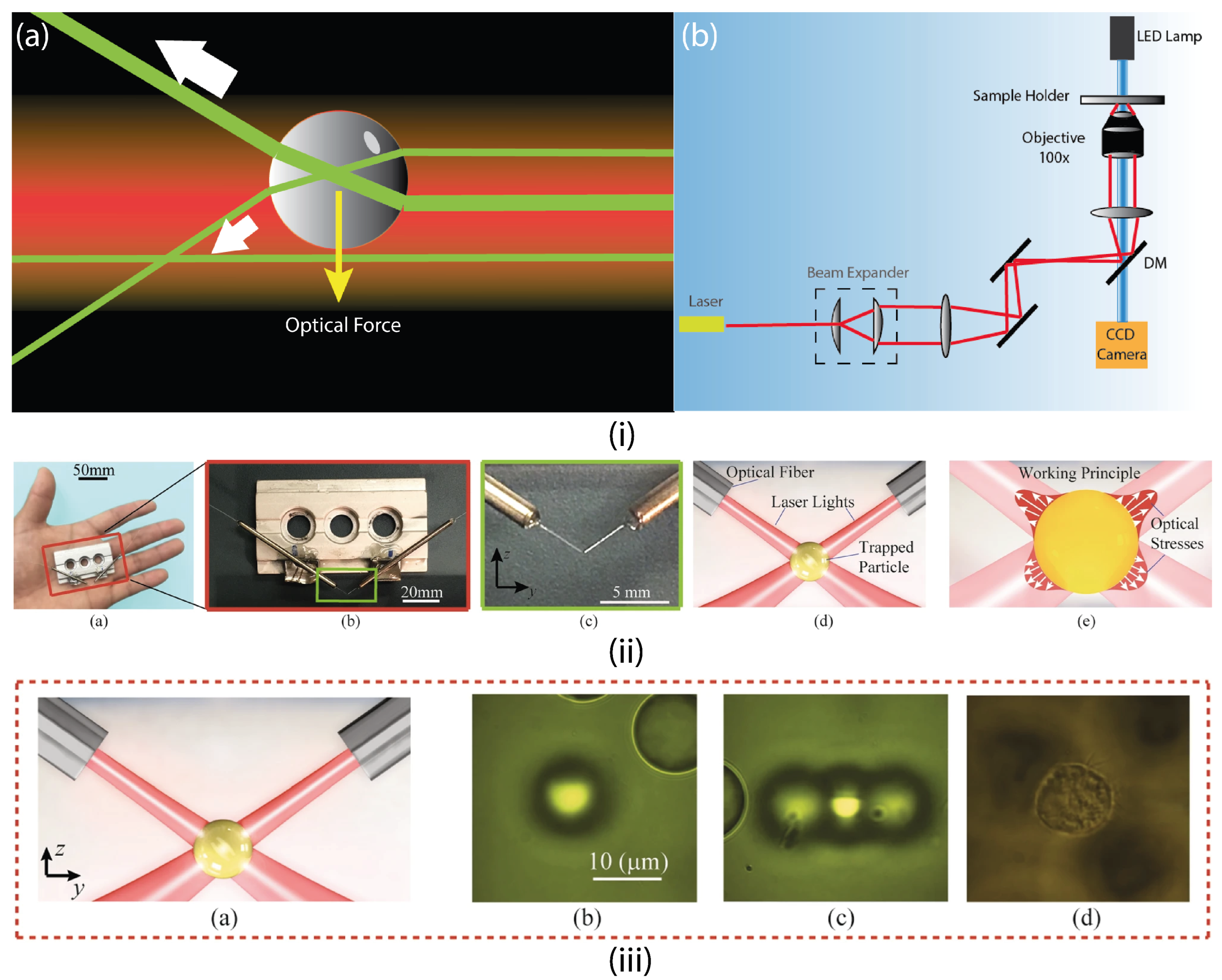
4.1.1. Optical Tweezers (OT)

Optical tweezers are the oldest and widely used method for micromanipulation using lights. Pioneered by Arthur Ashkin in the early 1970s [48], this remarkable invention received a Nobel Prize in 2018. In an optical tweezer, a trap can be formed by focusing a laser beam in an inverted microscope with the help of an objective lens of high numerical aperture (NA). The dielectric microparticle needs to have a refractive index different from the medium in which it stays. With the incident laser beam, it will experience a force due to the momentum transfer from the refracted beams. Two forces will appear here with the incident photons. One pushes the particle away, also known as the scattering force, and the other one ensures the balance of the particle in the cross direction. Now, if the size of the particle is larger than the wavelength (a λ ) of the laser beam, Mie scattering takes place, and then simple ray optics is enough to compute the optical forces. Gaussian laser beams tend to have an intensity profile with higher intensity in the middle of the beam and get dimmed along the cross direction. Now, as light beams hit the dielectric particle, the momentum of the refracted light balances the sideways movement of the particle but at the same time, as some light gets absorbed by the particle, there is a net momentum transfer to the particle from the incident photons. This momentum transfer results in a net force pushing the dielectric particle away. To overcome this unstable situation, an objective with high NA is used. This mechanism sharply focuses the trapping laser beam, which then gets refracted through the dielectric particle, resulting in a momentum change or force in the opposite direction of the scattering component of the previous force. Now, this ensures the stability of trapping along the beam.
However, if the particle is smaller than the wavelength of the laser beam (a λ ), then the scattering force component and the gradient force components can be calculated by assuming the particle is a point dipole using the following equations:
F scatt = I 0 σ n m c σ = 128 π 5 a 6 3 λ 4 m 2 1 m 2 + 2 2
Here, I 0 is the intensity of incident light, σ is the scattering cross section of the sphere, n m is the index of refraction of the medium, c is the speed of light in vacuum, m is the ratio n p / n m , and λ is the wavelength of the incident beam.
F grad = 2 π α c n m 2 I 0
where, α = n m 2 a 3 m 2 1 m 2 + 2   α is the polarizability of the sphere. The gradient force is proportional to the intensity gradient and points up the gradient when m > 1 .
However, when the wavelength of the laser is similar to the dimension of the particle ( a = 0.1 10 λ ), then neither of the two above-mentioned calculations are accepted, rather, a more complete theory is required to describe the forces. Most of the trapping laser beams use a wavelength of 1000 nm, as a result, many of the trapping particles of interest fall in this region (yeast, bacteria, or fabricated microbots at the micron scale). In this particular range, the theoretical calculations of the trapping force do not provide the physical intuition of optical trapping. To trap multiple particles in a single setup, a Spatial Light Modulator (SLM) is used to reflect the incident laser spot into a pattern before it enters the objective. SLM can create multiple patterns using Liquid Crystal on Silicon (LCoS) technology. In LCoS, multiple liquid crystal layers are sandwiched in between a cover glass/transparent ITO (Indium Tin Oxide) and an electrode layer. The electrode layer consists of multiple pixels and when a voltage is applied between the ITO and the electrode layer, the liquid crystal layers orient them accordingly to the direction of the electric field. This provides SLM the capability of creating a pattern only by reflecting light in the SLM panel [138].
Figure 5 shows the working principle of conventional optical tweezers along with the schematic and portable modular optical tweezers. Traditional OT systems employ an inverted microscope with a bulky design that is adequate for in vitro applications but lacks the practicality of in vivo considerations. A recent study has introduced all-fiber modular optical tweezers (AFMOTs), which can optically trap biological cells with reliability and freely move on a sample substrate [133]. They have successfully demonstrated the separation of the nontumorigenic breast epithelial cell line (MCF10A) from its cancerous PTEN mutants (MCF10 PTEN-/-). This technology has the potential to pave the way for a feasible and practical targeted drug delivery system in vivo. They even demonstrated the trapping of red blood cells in a living mouse. This takes the applicability of the actuation of small particles within the body using light one step further.

4.1.2. Optoelectronic Tweezers (OET)

Optoelectronic tweezers (OET) can sometimes be more useful than optical tweezers. Although both mechanisms use light for the manipulation of small particles, the underlying technique is more distinctive from that of an optical tweezer [76]. An OET device consists of several layers of elements. The top layer consists of an ITO transparent electrode; then there is a photoconductive electrode layer made out of amorphous silicon (a-Si:H) [139]. In an OET, light is projected into the device using the help of a digital projector and a digital micromirror device (DMD), then it passes through an objective lens directed towards the a-Si:H layer, where it creates the image of the projected light. With an AC electric bias, the pattern turns into a temporary electrode that creates a nonuniform electric field, which exerts a force on the dielectric particle through the process known as dielectrophoresis (DEP). If the dielectric particle is less polarizable than the surrounding media, then where the light illuminates in the substrate, the particle gets repelled, and where there is no illumination, the particle does not feel any forces. What makes OET particularly distinctive from optical tweezers is that optical tweezers use highly focused light beams (intensity > 105 W/cm2) to trap the particle, which could damage the biocells during long exposures. Whereas, in OET, to create virtual electrodes, a lower intensive light source (around 1 W/cm2) is enough. Even a commercial digital projector can be used as the light source in OET. OET does not require a coherent light source for trapping as optical tweezers because the light is only used to create the virtual electrodes, which create the DEP effect from the biased A.C. electric field. The photoconductive substrate a-Si:H is well conductive when illuminated and nonconductive when there is no illumination. Because of the use of a-Si:H (which is abundantly used in solar cells), the setup of OET is inexpensive compared to the optical tweezers system. However, this technique of creating a trap is not fully utilized in biomedical applications directly, but the separation of biological cells and, consequently, the medical diagnosis are proposed [139,140].

4.1.3. Electrothermoplasmonic Nanotweezers

In conventional optical tweezers, a high-resolution trapping is difficult to achieve because of the diffraction-limited trapping potential well. Moreover, a high laser power is required to form a stiff trap that can be transported over long distances. To overcome this, plasmonic tweezers came into action. In plasmonic tweezers, surface plasmons are used to create confined hotspots that allow for more precise trapping of diverse nanostructures and materials. This review of plasmonic tweezers has discussed the birth of technology and the uses and limitations of the system [141]. Plasmonic nanotweezers systems can produce a highly confined and stronger electromagnetic field in the region of nanoantennas. This allows one to generate strong optical gradient force, and the intensified electromagnetic field provides a high optical gradient force and confined trapping potential. This allows stable trapping for the nano-level particles. However, this technique has its drawbacks. The trapping largely depends on Brownian diffusion, which can be sluggish for some applications. There is also the possibility of losing dynamic control. Ndukaife et al. proposed a novel nanotweezer technique called Hybrid Electrothermoplasmonic Nanotweezer (HENT) [142]. In a HENT, the plasmonic nanoantenna’s intrinsic photo-induced heating is paired with an external AC electric field to produce on-demand large-scale microfluidic flow. The induced microfluidic flow allows suspended nanoparticles to be delivered quickly to a lit plasmonic nanoantenna, and the trapping of nanoparticles takes place in a matter of seconds.

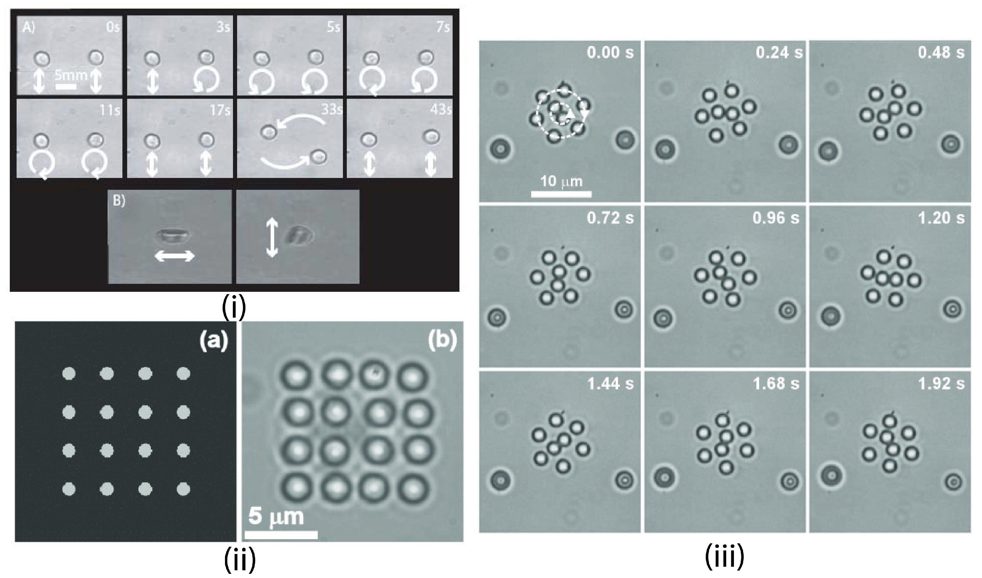
4.1.4. Trapping Multiple Particles

The maneuvering of microrobots using light may necessitate multiple particle trapping. Microrobots are frequently designed with multiple handles to provide better control. Multiple traps can be set using different methods, such as the inclusion of scanning mirrors [143], acousto-optic modulators [144], or a spatial light modulator (SLM) [145]. The former two are essentially beam-splitting time-sharing systems in which a single beam is quickly scanned over numerous targeted areas, resulting in multiple traps. SLM essentially divides the incident beam of light into a pattern of multiple traps [146]. A liquid crystal on silicon (LCoS)-based SLM reflects the light beam according to the computer-generated hologram (CGH) displayed on the panel. This not only provides for dexterity in trap position control, but also allows for simultaneous control of multiple traps. Rotation on its own axis is a critical component of many traps. The entrapped sphere can be rotated on its axis by transferring angular momentum. This is often accomplished by rotating an interference pattern [147] or a fixed aperture in the optical line [148]. The spin angular momentum content of several optical traps can be generated and controlled using a single SLM unit [145]. More advanced beam-steering and multiple trap-generating systems use acousto-optic deflectors (AODs) to modulate the optical trap. Multiple traps and beam steering are depicted in Figure 6.

4.1.5. Passive Trapping Manipulation

Optical manipulation can be done in a passive manner without actually trapping the particles. In conventional optical trapping, if the particle is small enough, the optical forces become dominant and as a consequence of momentum balance, a trap can be formed. However, without making it a static trap and making spatial variations in the optical field, a microscopic particle can be manipulated without being trapped. By utilizing the light’s momentum, it can generate lift or push a thin layer of foil which is analogous to the hydrodynamic thrust [150].

4.2. Fabrication Process

Photolithography is usually used to fabricate microbots. The 2PP method of nanoprinting was first introduced in 1998 [151]. Many times the 2PP is called by different names such as two-photon-absorbed photopolymerization [151], two-photon induced polymerization [152], two-photon lithography [153], sometimes 3D laser lithography or DLW [154]. In the 2PP fabrication process, a tightly focused near-infrared laser beam is projected to the photoresist. The motion and trajectory of the beam are controlled and the photoresist gets exposed to the focused laser beam accordingly. The smallest focus point of the laser is called a voxel or volumetric pixel. This process builds the input structure inside the photoresist layer by layer, which can essentially create a 3D structure from these 2D layers. Figure 7 describes the DLW process and advanced fabrication techniques. After directly writing the structure, the photoresist needs to be developed. To develop the printed 3D structure, propylene glycol monomethyl ether acetate (PGMEA) and isopropyl alcohol (IPA) are usually used. A brief comparison between the different fabrication techniques is presented in Table 2.

4.2.1. Material Selection

Being the main constituent of the substrate to be manufactured, it is crucial that the material be biocompatible, biodegradable, and have suitable mechanical, physical and chemical properties. Photopolymer inks are widely used for laser printing into complex 3D structures. Monomers, oligomers, and macromers undergo photopolymerization, underlining the core of the photochemical reaction process. Predefined 3D structures are created as the initiators in ink absorb laser energy, subsequently initiating layer-by-layer polymerization. IP-resist photoresists are used in applications that require high precision and structural integrity. Easy handling features along with submicrometer resolution make this group of resins very desirable for the fabrication of microbots. There are a wide variety of resins available, IP-PDMS, IP-n162, IP-Visio, IP-Q, IP-S, IP-Dip, IP-G, and IP-L [156]. Each resin has its own specialty, with possible applications of all resins hovering around material science, cell and tissue engineering, microfluidics, drug delivery, and microbots. Hwang et al. used the negative tone photoresist IP-G for fabricating multifunctional Janus helical microswimmers, with the resin providing autofluorescence and magnetic properties [157]. The latter was incorporated using the shadowing of the metallization process using electron beam evaporations. The ability of the microswimmers to respond to both fluorescence and weak magnetic fields could be useful in theranostic applications.
Along with flexibility, thermal and high mechanical stability is a crucial requirement for a microbot. A fully cross-linked SU-8 photoresist has approximately 4–5 GPa Young’s modulus, ∼200 °C Tg (glass transition temperature), and ∼380 °C degradation temperature [158]. For in vitro and in vivo biomedical applications, Elizabeth et al. designed a microbot system using SU-8 and polydimethylsiloxane (PDMS), which included an untethered magnetic tumbling microbot, a rotating permanent magnet of two degrees of freedom and an ultrasound imaging system has been designed [159]. When studying the movement of sperm flagella in the bovine oviduct, microtubes using IP-Dip were manufactured for maneuvering in complex biological environments [160]. These microtubes could be used to release sperm cells at a certain location, ensuring the start of fertilization.
In addition to the above-mentioned photopolymer inks, hydrogels that can be photo-cross-linked can be utilized for 3D printing. Gelatin methacrylate (GelMA) hydrogels were manufactured using a 3D bioplotter for bone tissue engineering applications [161]. The incorporation of gold nanoparticles ensured the attenuation of the substrates during imaging. Furthermore, the GelMA hydrogel consisting of platelet-rich plasma was 3D printed and used for the repair of osteochondral defects [162].

4.2.2. 3D Printing

Through a layer-by-layer deposition process, 3D printing (also known as “additive manufacturing” or “rapid prototyping”) can convert computer-aided and planned virtual 3D models into actual 3D constructs/objects. Since its inception, 3D printing has piqued the curiosity of researchers and engineers who want to learn more about the fabrication process and the composition–structur property relationship of printed 3D objects to realize its immense potential for use in a number of industries. 3D printing may surely assist the field of microrobotics and progress the design and development of functional microbots in a personalized manner owing to its special inherent advancements.

4.2.3. Solid Free Form Fabrication Techniques (Rapid Prototyping)

Metal-based additive manufacturing (MAM) techniques, such as selective laser melting (SLM) and electron beam melting (EBM), are computer-controlled fabrication processes based on layer-wise manufacturing principles. A family of fabrication processes was developed to make engineering prototypes in the minimum lead time based on a CAD model of the item. The creation of a 3D structure occurs in relation to the layer-by-layer stacking of 2D cross-section models. Regarding the conventional methods discussed in the previous section, solid free-form fabrication (SFF) can be used towards obtaining specificity, i.e., the control of scaffold size, shape, distribution, and interconnectivity of the scaffold [163]. The SFF fabrication technique is ideal because the macroscopic and microscopic structures can be predefined, which is uncontrollable in most of the fabricated substrates. The vital advantage of SFF over other techniques is its ability to produce parts with highly reproducible architecture and compositional variations. Ability to control matrix architecture (size, shape, interconnectivity, branching, geometry, and orientation), yielding a biomimetic structure by varying in design and material composition. Kai et al. demonstrated the use of SFF in fabricating a two-level bone tumor repair biomaterial. The ability to control the mechanical property, biological effects, and degradation kinetics of the bone tissue engineering substrate facilitated the rapid growth of the bones of patients [164]. Although widely used, SFF has its own drawbacks. It is expensive and, most importantly, the range of materials that can be used will depend on the fabrication technique, thereby limiting its potential. Various SFF techniques and their potential applications, along with their drawbacks, are mentioned in the following Table 2.

4.2.4. Fused Deposition Modeling (FDM)

Fused Deposition Modeling is a type of Rapid Prototyping (RP) method that deposits thermoplastic layer by layer [165]. Initially, FDM was used to fabricate solid physical structures, but to make scaffolds that can be used as therapeutic substrates, it is necessary that there are pores and that the pores are interconnected [166]. Therefore, the adjustment of the parameters in the FDM apparatus results in the production of a porous three-dimensional scaffold. Hutmacher et al. used FDM to fabricate PCL scaffolds for the seeding of fibroblasts. The results showed that the fibroblasts had proliferated on the scaffold, and a large presence of extracellular matrix was observed, leading to the formation of bridges between the pores [166]. Similarly, different cell types can be cultured in substrates fabricated using FDM by changing the pore size and interconnectivity. Moreover, the orientation of cells can be maintained by manipulating the hierarchical organization of the scaffold. Recently, researchers successfully fabricated a poly(vinyl alcohol)/ β -tricalcium phosphate composite scaffold for bone tissue engineering using FDM. The pre-determined architecture was useful in ensuring quick bone mineralization [167]. FDM’s advantage over other conventional techniques makes it a viable candidate for both soft and hard tissue engineering [168].

4.2.5. Stereolithography (SLA)

Scaffolds can be synthesized using the Stereolithography (SLA) process as described in previous research [169,170]. CAD software is used to design the architecture of the substrate to be fabricated. Firstly, a pre-polymer solution is prepared. Then, the digital light processing chip is used to create dynamic photomasks that create cross-sectional images of the 3D microstructure, which are then projected onto the prepolymer solution using a UV light source. Polymerization occurs when the liquid pre-polymer solution is exposed to the light source. A layer-by-layer 3D microstructure is obtained with controlled pore size and porosity [169]. For applications in bone tissue engineering, a poly(propylene fumarate) (PPF) scaffold was fabricated using SLA [171]. Fisher et al. developed a PPF scaffold using the salt-leaching technique for bone healing. Although the scaffold demonstrated good mechanical and biological properties, the lack of appropriate internal architecture led to minimal cell proliferation and attachment [172]. The former process showcased superiority over the latter. Previously, this RP technique was widely used in utilizing and analyzing data obtained from CT and MRI images. A combination of medical imaging and SLA has bought forth the possibility of producing anatomically shaped implants like vascular grafts. Lermusiaux et al. fabricated a life-size anatomical model of an abdominal aortic aneurysm with the aid of images obtained from the patient’s CT scan [173]. In vivo implantation of such devices poses great difficulties, but these models help surgeons pre-plan for life-threatening circumstances. Micro-tissue models fabricated using SLA were assembled digitally using bubble-propelled microbots [174]. The 3D stereolithographic technique was used to fabricate multi-material cantilevers that can mimic the native myocardium, with potential applications in sensor development and biohybrid actuators [175]. For superior speed in grabbing and cargo carrier, a hydrogel that could be manipulated using near-infrared light was fabricated using N-isopropylacrylamide [176].

4.2.6. Selective Laser Sintering (SLS)

Fabrication of tissue engineering substrates using SLS is done by moving the laser beam sinters heat-fusible powders in areas corresponding to the CAD geometry model one layer at a time to build the solid part [177]. After each layer is finished, a new layer of loose powder is dispersed across the surface. The powders are gradually bound together by the laser beam into a solid mass that creates the shape of the 3D component. The particles are loose in nonsintered areas and can be drained out of the completed portion. Scaffolds with decreased stiffness can be made using the SLS fabrication technique for soft tissue engineering. A substrate for cardiac tissue engineering was made out of poly(caprolactone); the substrate has the right mechanical properties, as well as the needed porosity and interconnectivity levels [178]. In 2013, researchers developed a PCL- β -tricalcium phosphate scaffold for seeding adipose-derived stem cells using SLS. Layer-by-layer additive manufacturing process was helpful in achieving a predetermined internal architecture and mechanical stability that was profoundly superior to conventional techniques in influencing high cell attachment and proliferation [179].

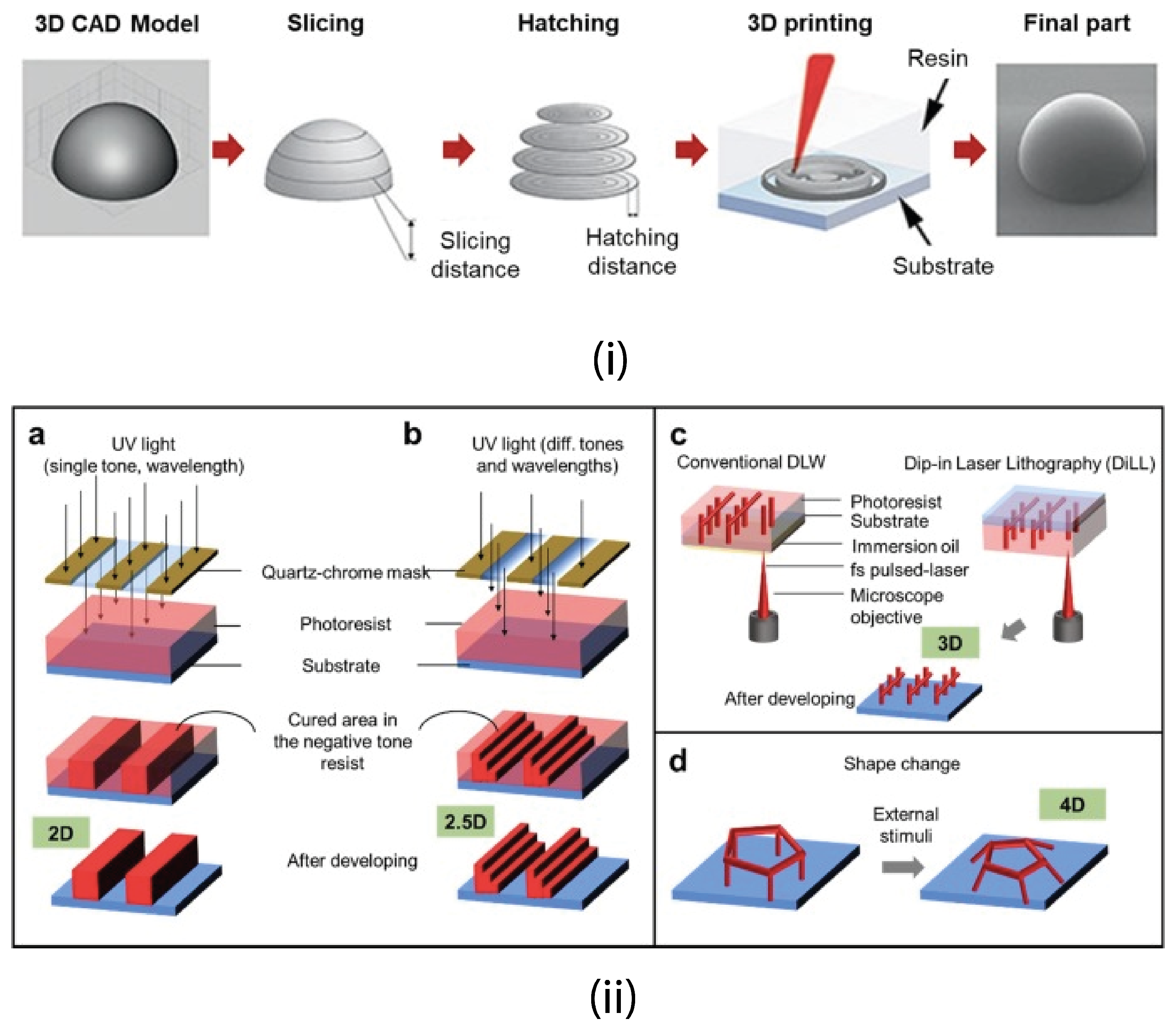
4.2.7. Direct Laser Writing

Multi-photon polymerization (MPP) for DLW is a technique that allows nm-sized structures to be built with a spatial resolution of fewer than 100 nm [156]. The polymerization process can be started by nonlinear absorption within the focal volume when the beam of an ultrafast laser is firmly focused on the volume of a transparent, photosensitive material. DLW allows the construction of freestanding, easily assembled, fully 3D structures by shifting the beam focus three-dimensionally inside the material. A variety of hybrid compounds of acrylate, epoxy, and organic–inorganic hybrid compounds have been used in the process [180].
Table 2. Comparison between different fabrication techniques.
Fabrication TechniqueApplicationsResolutionLimitationsReferences
Fused Deposition ModellingTransport, sensing, self-propelling vehicles100 μmLimited dimensional accuracy Slower printing speeds [156,181,182]
SLSScaffold base tissue engineering, drug delivery vehicles45 μmLimited SLS materials, poor mechanical properties, low surface quality [183,184,185]
SLAActuators, lab on a chip, microtissue models, microbots3 μmExpensive, printing larger prints is difficult [174,175,176]
DLW (or 2PP/MPP)Microbots, microfluidic channels, drug delivery vehicles, scaffolds70–100 nmVarying mechanical strength, material specificity [12,157,186,187,188]

4.3. Possible Workspace

One of the most crucial aspects of light-activated microbots is where they may be used effectively. For example, the current technology of microbot manipulation using light is not sufficient enough to penetrate nontransparent media, which limits its workspace in deep locations such as inside a living body. One way to overcome the problem is to use larger wavelengths (e.g., NIR lights). The study showed that light with short wavelengths within the visible range has a penetration depth of 0.5–2.5 mm. In this case, the reason for less penetration is both absorption and scattering of the incident light. Depending on the wavelength of the visible light, 15–40% incident light is reflected. With increasing wavelength, the penetration becomes deeper and with 600–1600 nm wavelength range, absorption of light reduces and scattering overpowers the absorption. Using light from this wavelength range can result in a penetration depth of 8-10 mm [189]. Moreover, with increasing wavelength, the penetration of light increases to a certain point and then drops. The maximum penetration of tissue occurs in the wavelength region of 900–1100 nm. This is one of the reasons why most optical tweezers operate at a wavelength around 1000 nm for biomedical applications, and also it reduces the chance of photodamage while ensuring stable trapping of the microparticles. Penetration also depends on the diameter of the light beam. A wide light beam results in greater penetration into the tissue [190]. However, penetration of this magnitude is not enough to perform in vivo operation of microbots inside the human body. Another study claimed that they were able to remove a blockage in the subdermal capillaries of living mice, which is an in vivo operation [191]. Although the possible workspace for light-actuated microbots is still limited, with the development of the technology, it is possible to perform the operation from in vitro to in vivo.

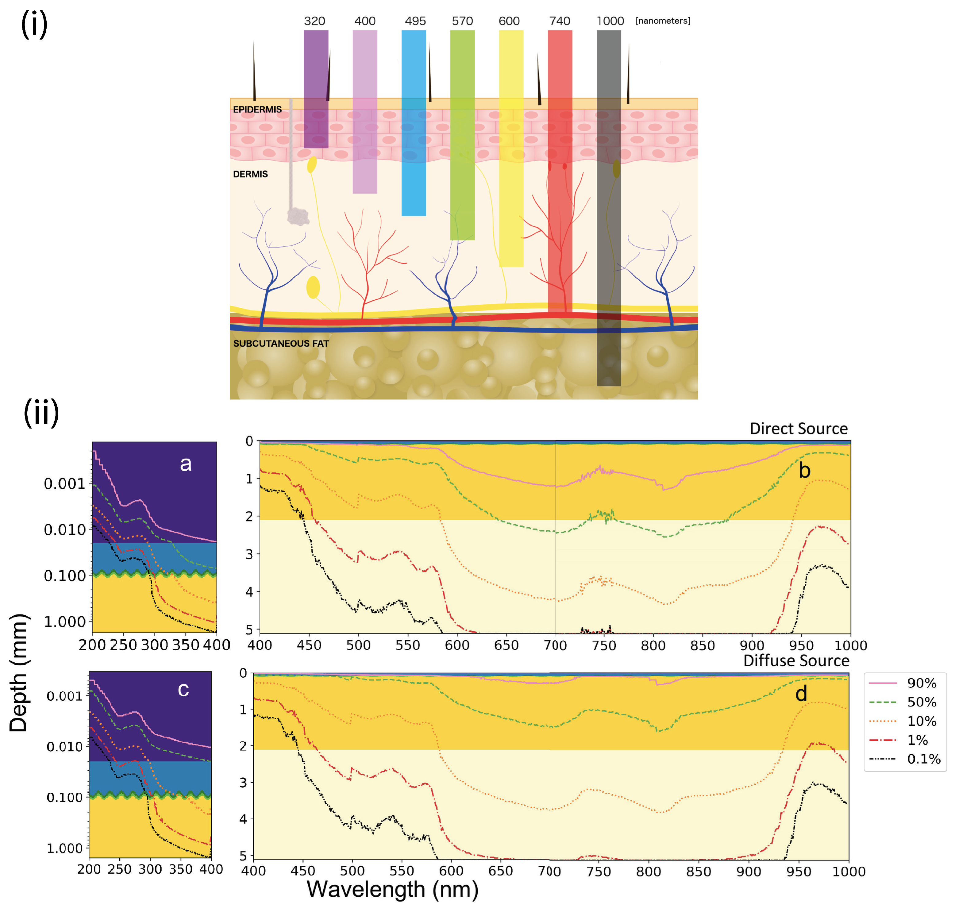
4.4. Wavelength Dependency and Trapping Efficiency

The wavelength dependence is very crucial when dealing with biocells. The specialized microbot to perform in vivo tasks must be designed considering the impact of the laser on the cells. The penetration of light through the skin for different wavelengths is visualized in Figure 8. Ideally, lasers of any wavelength can be used to trap microscopic particles, but only a few wavelengths are considered to be usable because of the factors of heating and photodamage of the cells. The first thing that comes to mind is how much heat will be produced in how large of an area. It is found that a laser at the near-infrared wavelength of 1064 nm can cause a temperature increase of up to 1.45 °C with a power increase of 100 mW in the sample [192]. It is also calculated that lasers of 1064 nm wavelength can cause a temperature rise 4.5 times higher than that of a 980 nm laser. However, at the same time, the samples are often surrounded by water and a 980 nm wavelength laser causes 3.5 times more heating than a 1064 nm laser [193]. Studies showed that high-intensity laser beams could penetrate cells, posing a risk of photodamage [194,195,196]. Usually, optical damage is characterized in two ways. The first is the efficiency of cloning and the other is the regular rotation of Escherechia Coli bacteria [197]. It is reported that a trapped wavelength of 1064 nm laser with 88 mW power in ovary cells from a Chinese Hamster (CHO) has reduced the cloning rate by a significant amount, and only after twenty minutes of exposure, the cloning efficiency decreased to zero percent [195]. Another study was conducted to measure the stress response of Caenorhabditis elegans during exposure to a high-power laser from an optical tweezer [198]. It is found that for the same laser power and exposure period, the gene expression and calculated temperature of the test sample depend on the wavelength of the laser. The stress response is measured by the expression of a heat shock-responsive gene within C. elegans. Another study also tried to quantify the damage of Escherichia coli bacteria by measuring the rotation rate of bacteria with applied laser power, wavelength, and exposure period [197].
A 980 nm laser exhibits a minimum risk of damage on a normalized scale, and both 830 nm and 1064 nm pose greater photodamage risk. Another research studied the effect of the 1064-nm laser on temperature, DNA structure, viability, and pH of CHO and human sperm cells in both continuous wave (CW) and pulse mode trapping [201]. For CW trapping, an average of 1 °C increase in temperature per 100 mW laser power is observed up to 400 mW. Damage to different cell types varies depending on the exposure time, wavelength, and power of the laser. For example, this research reveals that increasing laser power from 1 mW to 100 mW at 1 mm spot size ranged from 0.0025 °C to 0.26 °C and from 0.03 °C to 2.85 °C at depths of 15.9 and 4.9 mm in the adult and newborn brain, respectively [202]. Long-term exposure to the high-powered laser may cause physiological damage to the cells, and long-term use might pose a fatal risk.

5. Imaging

Another Important consideration for light-actuated microbots is the imaging of the workspace. For other control modalities, imaging may not always be required for the operation of the system, but when it comes to light actuation, it is necessary to monitor the entire process using a sophisticated imaging setup. Imaging is required to pinpoint movements and navigate the work space. Along with the camera, various light sources and dyes are used to get a high-contrast and distinguishable image of the workspace. Imaging could be not only optical but also other different modalities, such as magnetic imaging, ultrasound imaging, photoacoustic imaging, radiative imaging, or a combination of multiple imaging systems. When it comes to biomedical applications, optical imaging in vivo is very difficult because of the penetration limitation of visible light wavelengths and limitation of light intensity that causes physiological damage. Rather than using only one mode of imaging, a fusion of multiple imaging techniques is often used [203,204]. Light-actuated microbots can employ these strategies to navigate better and locate the operation site.

5.1. Optical Imaging

Before imaging with an optical system, there are some things that must be in order. There are several advantages and disadvantages to employing an optical imaging system. The light must travel in a straight line through all available mediums before reaching the camera sensor or the eyes. The camera sensor, camera filter, objectives for adequate magnification, various light sources, and dyes for acceptable picture contrast are only a few of the critical components of an optical imaging system. Optical imaging is extremely difficult because of so many parameters. The prospect of optical photographic imaging is reviewed in detail by Dhawan and his team [205].
If the workspace is transparent where light can pass through, then imaging with a camera (CCD/CMOS) camera is a viable option. Often, a camera is used for auxiliary control and localization of the robot. Imaging systems primarily track the motion of any particles in the workspace, which is vital in controlling and actuating the movements of microbots. However, in in vivo application, imaging in the visible wavelength range might not be an ideal choice, as it is nearly impossible for visible light to penetrate through the tissue of the body. From the figure, it can be seen that only a few hundred nanometers of penetration through the skin is possible with visible light. If we want to penetrate through the tissue, then the wavelength of the light has to be beyond the NIR wavelength. Therefore, Ultrasound, X-ray fluoroscopy, Photoacoustic Computed Tomography (PACT), positron emission tomography (PET), etc. are needed to obtain decent imaging of the workspace. Incorporating these additional features in the microbot actuation increases the complexity along with the overall capability of the system.
If the camera is used with a microscope, it is critical to utilize the appropriate objective lens with the right magnification. It is preferable if there are many magnification settings available so that the exact position of the microbots may be located faster. Particularly for optical trapping, an objective with a higher numerical aperture is required to focus the collimated laser light properly.
Different light sources might also be required to illuminate the workspace to capture a bright image. Optical trapping with an inverted microscope uses a white LED light to illuminate the sample. For better imaging, along with the white LED, a Halogen light source is also used to get a better contrast of the image and distinguish the microbot from the medium of the workspace. Sometimes different dyes are used to get the best results during imaging. Furthermore, fluorescence coating is a clever idea to image micro-robots in operation [206,207].

5.2. Photoacoustic Imaging

Where conventional optical imaging fails, photoacoustic imaging comes into play. The basic principle of photoacoustic imaging is that impulsive optical energy is absorbed by the tissues and is transformed into sonic waves, which are then detected to provide high-resolution tomographic photographs with decent optical contrasts. A recent study performed deep tissue imaging and targeted in vivo navigation of microbots in the intestine of mice using Photoacoustic Computed Tomography (PACT) [208]. Irradiated NIR light is used to release the drugs once they reaches the targeted region, and the whole process is visualized in real-time in vivo using the PACT imaging system integrated into the microrobotic system. Current photoacoustic systems operate in serial or parallel configurations with the help of ultrasonic transducers. To reduce the cost and complexity of the imaging by using a single element ultrasonic transducer, the throughput of the imaging also decreases. Deep penetration (48 mm) with a high data acquisition rate (50 Hz) in vivo operation of single impulse panoramic photoacoustic computed tomography (SIP-PACT) has been demonstrated [209,210,211,212,213]. A 1000-fold less scattering nature of sound compared to light allows it to travel through biological tissues, allowing for more detailed imaging of the system [214]. Recently, a slightly updated version of photoacoustic imaging, known as photoacoustic topography through an ergodic relay (PATER), was introduced [215]. This imaging technique uses a single-element ultrasonic transducer to get a result similar to that of the multi-element one. In that study, high-speed imaging of the propagation of the blood pulse waves inside mice is demonstrated in that study. The rendering of volumetric snapshots of spectrally resolved optoacoustic data in real-time paved the way for a new fifth-dimensional optoacoustic imaging [216]. This technique of imaging has already been demonstrated in both mice and humans. Photoacoustic imaging is favorable for light-actuated microbots, even with a metal coating, which is often done to achieve certain capabilities of robots. Photoacoustic imaging does not interfere with the light-controlled navigation system, and pulsated illumination (<10 ns) in the biological medium makes it less invasive for extended operation.

5.3. Magnetic Imaging

Magnetic imaging is used primarily in the diagnosis of diseases to look inside the human body. The imaging is done with highly intense fluctuating magnetic fields. The widely used magnetic imaging system is known as Magnetic Resonance Imaging or MRI. In MRI, the static and gradient magnetic field orients and excites the hydrogen nuclei inside the body to construct a detailed image of the body with high accuracy. A powerful magnetic field is utilized to align the magnetic nuclear spins, and then a radio frequency (RF) pulse perturbs the alignment. Nuclear spins experience resonant absorption and then return to the original state, emitting energy that can be detected and processed to generate an NMR spectrum, when the frequency of the electromagnetic pulse is appropriately tuned (depending on the intensity of the magnetic field) [217]. MRI is mainly used in neuroimaging, cardiovascular imaging, musculoskeletal imaging, gastrointestinal imaging, etc. MRI can sometimes be used to control microbots that are designed to operate magnetically [218]. One of the major advantages of magnetic imaging is that it can generate three-dimensional (3D) images in real-time, which can be very useful in the maneuverability of the microbots. In general, MRI is a very safe imaging system, but it can be devastating if the patient is wearing pacemakers, heart rings, cochlear implants, or any other metallic implants inside the body. The use of magnetic particle imaging (MPI) and magnetic maneuverability using a magnetic field at the same time has been demonstrated by Sharif et al. [219]. Magnetic imaging can be troublesome for pure light-actuated systems if ferromagnetic materials are used in the fabrication of the microbots. The imaging system might interfere with the proper actuation of the robots.

5.4. Ultrasonic Imaging

Ultrasound (US) imaging is commonly used in medical diagnostics, as well as in the examination of the ovaries during pregnancy and to monitor the health of the growing baby. Various US modes are used on the basis of their applicability. B-mode (brightness mode) US uses multiple transducers and simultaneously scans through the body and creates a 2D tomographic image. Other mentionable techniques are the C mode, the M mode (motion mode), the Doppler mode, the pulse inversion mode, and the harmonic mode. The harmonic mode provides better imaging capabilities. in harmonic mode, after passing through biological tissues, a transducer delivers fundamental ultrasonic pulses into the body, and a centered, narrow beam of harmonic overtone is reflected back. Ultrasonic imaging has been used successfully in the microrobotic operation of targeted drug delivery [159,220]. This technique could be used to image light-actuated microbots, since it does not interfere with the basic control mechanism of light-actuated microbots. The disadvantage of using ultrasonic imaging is the finest feature that it can resolve. Until now, the US has only been able to achieve millimeter-scale resolution, but some promising research has been done to bring imaging down to the nanoscale level, which broadens the usefulness of technology to microrobots in biomedical applications [221,222]. The most recent advances and challenges in imaging and tracking microrobots that use known medical ultrasound imaging technology are reviewed and summarized in this article [223].

5.5. Radiography Imaging

Radiography imaging is a technique that refers to a variety of studies that need the use of X-ray, gamma-ray, or any other ionizing radiation technology to visualize the internal organs of the body. Radiography has been used for a long time in medical applications, but it is also used in manufacturing industries. In industry, radiography is used to examine the integrity of the specimen and internal structures. All of these radiations are basically electromagnetic radiation. The wavelength determines the difference between distinct types of electromagnetic radiation. X-ray and gamma-ray offer the shortest workable wavelengths, which allows them to penetrate or travel through different materials, including metals. This kind of imaging can be used to visualize microbots in the absence of biological substances. Radiation sometimes makes it incompatible with working with biological samples for an extended period of time.

6. Conclusions

The primary goal of this study is to provide an overview of light-powered microbots and how they might be used in current biomedical applications. Light-actuated microbots can be used for everything from biological medical applications to microlevel mechanical integration with extreme accuracy and precision. Because of the large spectrum of materials accessible, light is minimally invasive in therapeutics and is comparably safer than other control modalities. One of the main objectives of this review is to highlight the challenges and potential of light-powered microbots. The design aspects of microbot fabrication are shown so that future research might overcome the challenges and limitations of the past. The field of light robotics is still in its embryonic stage. Precision control of microbots using light has to overcome many shortcomings, from fabrication and biocompatibility to imaging and dexterous control for in vivo applications. Developments in the field of light-powered microrobots should greatly benefit from interaction and collaboration between researchers in different disciplines. Small-scale robotics combined with various integrated control methods would provide a better solution to current challenges, given the increasing interest in research and collaboration between different disciplines. Finally, we believe that microbots will successfully move from fascinating laboratory equipment to technology with social benefit in the not-too-distant future and that light will be one of the motors driving the next generation of microbots. It is expected that in the near future these microbots will transform medical treatment and diagnosis by making them less invasive, lowering the dosages of the medications, and opening up a whole new world of possibilities.

Author Contributions

Conceptualization, M.F.J. and K.P.; formal analysis, M.F.J. and M.P.; investigation, M.F.J. and K.P.; resources, M.F.J. and M.P.; writing—original draft preparation, M.F.J., M.P. and K.P.; writing—review and editing, M.F.J., M.P. and K.P.; visualization, M.F.J.; supervision, K.P.; project administration, K.P.; funding acquisition, K.P. All authors have read and agreed to the published version of the manuscript.

Funding

This research work is supported by UMass Dartmouth’s Marine and Undersea Technology (MUST) Research Program funded by the Office of Naval Research (ONR) under Grant No. N00014-20-1-2170.

Institutional Review Board Statement

Not applicable.

Informed Consent Statement

Not applicable.

Data Availability Statement

Not applicable.

Conflicts of Interest

The authors declare no conflict of interest. The sponsor had no role in the design of the study, in the collection, analysis, or interpretation of data; in the writing of the manuscript or in the decision to publish the results.

References

  1. Garcia, E.; Jimenez, M.A.; De Santos, P.G.; Armada, M. The evolution of robotics research. IEEE Robot. Autom. Mag. 2007, 14, 90–103. [Google Scholar] [CrossRef]
  2. Halder, A.; Sun, Y. Biocompatible propulsion for biomedical micro/nano robotics. Biosens. Bioelectron. 2019, 139, 111334. [Google Scholar] [CrossRef] [PubMed]
  3. Koleoso, M.; Feng, X.; Xue, Y.; Li, Q.; Munshi, T.; Chen, X. Micro/nanoscale magnetic robots for biomedical applications. Mater. Today Bio 2020, 8, 100085. [Google Scholar] [CrossRef]
  4. Li, J.; de Ávila, B.E.F.; Gao, W.; Zhang, L.; Wang, J. Micro/nanorobots for biomedicine: Delivery, surgery, sensing, and detoxification. Sci. Robot. 2017, 2. [Google Scholar] [CrossRef]
  5. Wang, B.; Zhang, Y.; Zhang, L. Recent progress on micro-and nano-robots: Towards in vivo tracking and localization. Quant. Imaging Med. Surg. 2018, 8, 461. [Google Scholar] [CrossRef]
  6. Nelson, B.J.; Kaliakatsos, I.K.; Abbott, J.J. Microrobots for minimally invasive medicine. Annu. Rev. Biomed. Eng. 2010, 12, 55–85. [Google Scholar] [CrossRef] [Green Version]
  7. Bunea, A.I.; Engay, E.L.; Chouliara, M.; Bañas, A.R.; Glückstad, J. Rational design of light-controlled microrobots. In Advanced Manufacturing Technologies for Micro-and Nanosystems in Security and Defence; SPIE: Geneva, Switzerland, 2018; Volume 10804, p. 1080406. [Google Scholar]
  8. Suh, K.Y.; Seong, J.; Khademhosseini, A.; Laibinis, P.E.; Langer, R. A simple soft lithographic route to fabrication of poly (ethylene glycol) microstructures for protein and cell patterning. Biomaterials 2004, 25, 557–563. [Google Scholar] [CrossRef]
  9. Liu, C.C.; Jin, Z. Applications of microfabrication and micromachining techniques to biotechnology. Trends Biotechnol. 1997, 15, 213–216. [Google Scholar] [CrossRef]
  10. Yang, L.; Chang, L.; Hu, Y.; Huang, M.; Ji, Q.; Lu, P.; Liu, J.; Chen, W.; Wu, Y. An autonomous soft actuator with light-driven self-sustained wavelike oscillation for phototactic self-locomotion and power generation. Adv. Funct. Mater. 2020, 30, 1908842. [Google Scholar] [CrossRef]
  11. Sánchez, S.; Soler, L.; Katuri, J. Chemically powered micro-and nanomotors. Angew. Chem. Int. Ed. 2015, 54, 1414–1444. [Google Scholar] [CrossRef]
  12. Huang, Z.; Tsui, G.C.P.; Deng, Y.; Tang, C.Y. Two-photon polymerization nanolithography technology for fabrication of stimulus-responsive micro/nano-structures for biomedical applications. Nanotechnol. Rev. 2020, 9, 1118–1136. [Google Scholar] [CrossRef]
  13. Behkam, B.; Sitti, M. Bacterial flagella-based propulsion and on/off motion control of microscale objects. Appl. Phys. Lett. 2007, 90, 023902. [Google Scholar] [CrossRef] [Green Version]
  14. Martel, S. Bacterial microsystems and microrobots. Biomed. Microdevices 2012, 14, 1033–1045. [Google Scholar] [CrossRef] [PubMed]
  15. Shao, J.; Xuan, M.; Zhang, H.; Lin, X.; Wu, Z.; He, Q. Chemotaxis-guided hybrid neutrophil micromotors for targeted drug transport. Angew. Chem. 2017, 129, 13115–13119. [Google Scholar] [CrossRef]
  16. Kim, S.; Qiu, F.; Kim, S.; Ghanbari, A.; Moon, C.; Zhang, L.; Nelson, B.J.; Choi, H. Fabrication and characterization of magnetic microrobots for three-dimensional cell culture and targeted transportation. Adv. Mater. 2013, 25, 5863–5868. [Google Scholar] [CrossRef] [PubMed] [Green Version]
  17. Diller, E.; Giltinan, J.; Sitti, M. Independent control of multiple magnetic microrobots in three dimensions. Int. J. Robot. Res. 2013, 32, 614–631. [Google Scholar] [CrossRef]
  18. Sul, O.; Falvo, M.; Taylor, R.; Washburn, S.; Superfine, R. Thermally actuated untethered impact-driven locomotive microdevices. Appl. Phys. Lett. 2006, 89, 203512. [Google Scholar] [CrossRef]
  19. Erdem, E.Y.; Chen, Y.M.; Mohebbi, M.; Suh, J.W.; Kovacs, G.T.; Darling, R.B.; Böhringer, K.F. Thermally actuated omnidirectional walking microrobot. J. Microelectromechanical Syst. 2010, 19, 433–442. [Google Scholar] [CrossRef]
  20. Donald, B.R.; Levey, C.G.; McGray, C.D.; Paprotny, I.; Rus, D. An untethered, electrostatic, globally controllable MEMS micro-robot. J. Microelectromechanical Syst. 2006, 15, 1–15. [Google Scholar] [CrossRef]
  21. Pawashe, C.; Floyd, S.; Sitti, M. Multiple magnetic microrobot control using electrostatic anchoring. Appl. Phys. Lett. 2009, 94, 164108. [Google Scholar] [CrossRef]
  22. Nocentini, S.; Parmeggiani, C.; Martella, D.; Wiersma, D.S. Optically driven soft micro robotics. Adv. Opt. Mater. 2018, 6, 1800207. [Google Scholar] [CrossRef]
  23. Villangca, M.J.; Palima, D.; Banas, A.R.; Glückstad, J. Light-driven micro-tool equipped with a syringe function. Light. Sci. Appl. 2016, 5, e16148. [Google Scholar] [CrossRef] [PubMed] [Green Version]
  24. Gáspár, S. Enzymatically induced motion at nano-and micro-scales. Nanoscale 2014, 6, 7757–7763. [Google Scholar] [CrossRef] [PubMed] [Green Version]
  25. Nourhani, A.; Crespi, V.H.; Lammert, P.E.; Borhan, A. Self-electrophoresis of spheroidal electrocatalytic swimmers. Phys. Fluids 2015, 27, 092002. [Google Scholar] [CrossRef]
  26. Ding, X.; Lin, S.C.S.; Kiraly, B.; Yue, H.; Li, S.; Chiang, I.K.; Shi, J.; Benkovic, S.J.; Huang, T.J. On-chip manipulation of single microparticles, cells, and organisms using surface acoustic waves. Proc. Natl. Acad. Sci. USA 2012, 109, 11105–11109. [Google Scholar] [CrossRef] [Green Version]
  27. Ren, L.; Wang, W.; Mallouk, T.E. Two forces are better than one: Combining chemical and acoustic propulsion for enhanced micromotor functionality. Accounts Chem. Res. 2018, 51, 1948–1956. [Google Scholar] [CrossRef]
  28. Go, G.; Nguyen, V.D.; Jin, Z.; Park, J.O.; Park, S. A thermo-electromagnetically actuated microrobot for the targeted transport of therapeutic agents. Int. J. Control. Autom. Syst. 2018, 16, 1341–1354. [Google Scholar] [CrossRef]
  29. Sitti, M.; Wiersma, D.S. Pros and cons: Magnetic versus optical microrobots. Adv. Mater. 2020, 32, 1906766. [Google Scholar] [CrossRef]
  30. Erkoc, P.; Yasa, I.C.; Ceylan, H.; Yasa, O.; Alapan, Y.; Sitti, M. Mobile microrobots for active therapeutic delivery. Adv. Ther. 2019, 2, 1800064. [Google Scholar] [CrossRef] [Green Version]
  31. Medina-Sánchez, M.; Xu, H.; Schmidt, O.G. Micro-and nano-motors: The new generation of drug carriers. Ther. Deliv. 2018, 9, 303–316. [Google Scholar] [CrossRef]
  32. Yamamoto, D.; Shioi, A. Self-propelled nano/micromotors with a chemical reaction: Underlying physics and strategies of motion control. KONA Powder Part. J. 2015, 2015005. [Google Scholar] [CrossRef] [Green Version]
  33. Soler, L.; Sánchez, S. Catalytic nanomotors for environmental monitoring and water remediation. Nanoscale 2014, 6, 7175–7182. [Google Scholar] [CrossRef] [PubMed] [Green Version]
  34. Atkinson, I.C.; Renteria, L.; Burd, H.; Pliskin, N.H.; Thulborn, K.R. Safety of human MRI at static fields above the FDA 8T guideline: Sodium imaging at 9.4 T does not affect vital signs or cognitive ability. J. Magn. Reson. Imaging Off. J. Int. Soc. Magn. Reson. Med. 2007, 26, 1222–1227. [Google Scholar] [CrossRef]
  35. Amara, S.; Abdelmelek, H.; Salem, M.B.; Abidi, R.; Sakly, M. Effects of static magnetic field exposure on hematological and biochemical parameters in rats. Braz. Arch. Biol. Technol. 2006, 49, 889–895. [Google Scholar] [CrossRef] [Green Version]
  36. Ahmad, B.; Gauthier, M.; Laurent, G.J.; Bolopion, A. Mobile microrobots for in vitro biomedical applications: A survey. IEEE Trans. Robot. 2021, 38, 646–663. [Google Scholar] [CrossRef]
  37. Ergeneman, O.; Chatzipirpiridis, G.; Pokki, J.; Marin-Suárez, M.; Sotiriou, G.A.; Medina-Rodriguez, S.; Sanchez, J.F.F.; Fernandez-Gutiérrez, A.; Pane, S.; Nelson, B.J. In vitro oxygen sensing using intraocular microrobots. IEEE Trans. Biomed. Eng. 2012, 59, 3104–3109. [Google Scholar] [CrossRef]
  38. Hosney, A.; Abdalla, J.; Amin, I.S.; Hamdi, N.; Khalil, I.S. In vitro validation of clearing clogged vessels using microrobots. In Proceedings of the 2016 6th IEEE International Conference on Biomedical Robotics and Biomechatronics (BioRob), Singapore, 26–29 June 2016; pp. 272–277. [Google Scholar]
  39. Peyer, K.E.; Zhang, L.; Nelson, B.J. Bio-inspired magnetic swimming microrobots for biomedical applications. Nanoscale 2013, 5, 1259–1272. [Google Scholar] [CrossRef]
  40. Banerjee, H.; Shen, S.; Ren, H. Magnetically actuated minimally invasive microbots for biomedical applications. In Electromagnetic Actuation and Sensing in Medical Robotics; Springer: Berlin/Heidelberg, Germany, 2018; pp. 11–41. [Google Scholar]
  41. Glückstad, J.; Villangca, M.J.; Palima, D.Z.; Bañas, A. Light-actuated microrobots for biomedical science. SPIE Newsroom 2017. [Google Scholar] [CrossRef] [Green Version]
  42. Yan, Y.; Mehrmohammadi, M.; Jing, W. Non-invasive Photoacoustic Imaging of Magnetic Microrobot through Deep Non-Transparent Tissue. In Proceedings of the 2020 International Conference on Manipulation, Automation and Robotics at Small Scales (MARSS), Toronto, ON, Canada, 13–17 July 2020; pp. 1–6. [Google Scholar]
  43. Glückstad, J. Sculpting the object. Nat. Photonics 2011, 5, 7–8. [Google Scholar] [CrossRef]
  44. Palima, D.; Glückstad, J. Gearing up for optical microrobotics: Micromanipulation and actuation of synthetic microstructures by optical forces. Laser Photonics Rev. 2013, 7, 478–494. [Google Scholar] [CrossRef]
  45. Rodrigo, P.J.; Gammelgaard, L.; Bøggild, P.; Perch-Nielsen, I.R.; Glückstad, J. Actuation of microfabricated tools using multiple GPC-based counterpropagating-beam traps. Opt. Express 2005, 13, 6899–6904. [Google Scholar] [CrossRef]
  46. Ikin, L.; Carberry, D.; Gibson, G.; Padgett, M.; Miles, M.a. Assembly and force measurement with SPM-like probes in holographic optical tweezers. New J. Phys. 2009, 11, 023012. [Google Scholar] [CrossRef]
  47. Carberry, D.M.; Simpson, S.; Grieve, J.A.; Wang, Y.; Schäfer, H.; Steinhart, M.; Bowman, R.; Gibson, G.M.; Padgett, M.J.; Hanna, S.; et al. Calibration of optically trapped nanotools. Nanotechnology 2010, 21, 175501. [Google Scholar] [CrossRef]
  48. Ashkin, A. Acceleration and trapping of particles by radiation pressure. Phys. Rev. Lett. 1970, 24, 156. [Google Scholar] [CrossRef] [Green Version]
  49. Guix, M.; Weiz, S.M.; Schmidt, O.G.; Medina-Sánchez, M. Self-propelled micro/nanoparticle motors. Part. Part. Syst. Charact. 2018, 35, 1700382. [Google Scholar] [CrossRef]
  50. Mills, J.K.; Needham, D. Targeted drug delivery. Expert Opin. Ther. Patents 1999, 9, 1499–1513. [Google Scholar] [CrossRef]
  51. Bae, Y.H.; Park, K. Targeted drug delivery to tumors: Myths, reality and possibility. J. Control. Release 2011, 153, 198. [Google Scholar] [CrossRef] [Green Version]
  52. Deckert, P. Current constructs and targets in clinical development for antibody-based cancer therapy. Curr. Drug Targets 2009, 10, 158–175. [Google Scholar] [CrossRef]
  53. Hong, M.; Zhu, S.; Jiang, Y.; Tang, G.; Pei, Y. Efficient tumor targeting of hydroxycamptothecin loaded PEGylated niosomes modified with transferrin. J. Control. Release 2009, 133, 96–102. [Google Scholar] [CrossRef]
  54. Masood, F. Polymeric nanoparticles for targeted drug delivery system for cancer therapy. Mater. Sci. Eng. C 2016, 60, 569–578. [Google Scholar] [CrossRef]
  55. Mou, X.; Ali, Z.; Li, S.; He, N. Applications of magnetic nanoparticles in targeted drug delivery system. J. Nanosci. Nanotechnol. 2015, 15, 54–62. [Google Scholar] [CrossRef] [PubMed]
  56. Galvin, P.; Thompson, D.; Ryan, K.B.; McCarthy, A.; Moore, A.C.; Burke, C.S.; Dyson, M.; MacCraith, B.D.; Gun’ko, Y.K.; Byrne, M.T.; et al. Nanoparticle-based drug delivery: Case studies for cancer and cardiovascular applications. Cell. Mol. Life Sci. 2012, 69, 389–404. [Google Scholar] [CrossRef] [PubMed]
  57. Noyhouzer, T.; L’Homme, C.; Beaulieu, I.; Mazurkiewicz, S.; Kuss, S.; Kraatz, H.B.; Canesi, S.; Mauzeroll, J. Ferrocene-modified phospholipid: An innovative precursor for redox-triggered drug delivery vesicles selective to cancer cells. Langmuir 2016, 32, 4169–4178. [Google Scholar] [CrossRef] [PubMed]
  58. Kummer, M.P.; Abbott, J.J.; Kratochvil, B.E.; Borer, R.; Sengul, A.; Nelson, B.J. OctoMag: An electromagnetic system for 5-DOF wireless micromanipulation. IEEE Trans. Robot. 2010, 26, 1006–1017. [Google Scholar] [CrossRef]
  59. Diller, E.; Giltinan, J.; Lum, G.Z.; Ye, Z.; Sitti, M. Six-degree-of-freedom magnetic actuation for wireless microrobotics. Int. J. Robot. Res. 2016, 35, 114–128. [Google Scholar] [CrossRef]
  60. Cheang, U.K.; Meshkati, F.; Kim, H.; Lee, K.; Fu, H.C.; Kim, M.J. Versatile microrobotics using simple modular subunits. Sci. Rep. 2016, 6, 30472. [Google Scholar] [CrossRef] [Green Version]
  61. Roper, M.; Dreyfus, R.; Baudry, J.; Fermigier, M.; Bibette, J.; Stone, H.A. On the dynamics of magnetically driven elastic filaments. J. Fluid Mech. 2006, 554, 167–190. [Google Scholar] [CrossRef] [Green Version]
  62. Kim, D.; Liu, A.; Diller, E.; Sitti, M. Chemotactic steering of bacteria propelled microbeads. Biomed. Microdevices 2012, 14, 1009–1017. [Google Scholar] [CrossRef]
  63. Zhuang, J.; Wright Carlsen, R.; Sitti, M. pH-taxis of biohybrid microsystems. Sci. Rep. 2015, 5, 11403. [Google Scholar] [CrossRef] [Green Version]
  64. Weibel, D.B.; Garstecki, P.; Ryan, D.; DiLuzio, W.R.; Mayer, M.; Seto, J.E.; Whitesides, G.M. Microoxen: Microorganisms to move microscale loads. Proc. Natl. Acad. Sci. USA 2005, 102, 11963–11967. [Google Scholar] [CrossRef]
  65. Ahmed, S.; Wang, W.; Mair, L.O.; Fraleigh, R.D.; Li, S.; Castro, L.A.; Hoyos, M.; Huang, T.J.; Mallouk, T.E. Steering acoustically propelled nanowire motors toward cells in a biologically compatible environment using magnetic fields. Langmuir 2013, 29, 16113–16118. [Google Scholar] [CrossRef] [PubMed]
  66. Mohanty, S.; Zhang, J.; McNeill, J.M.; Kuenen, T.; Linde, F.P.; Rouwkema, J.; Misra, S. Acoustically-actuated bubble-powered rotational micro-propellers. Sens. Actuators B Chem. 2021, 347, 130589. [Google Scholar] [CrossRef]
  67. Park, J.; Kim, J.y.; Pane, S.; Nelson, B.J.; Choi, H. Acoustically mediated controlled drug release and targeted therapy with degradable 3D porous magnetic microrobots. Adv. Healthc. Mater. 2021, 10, 2001096. [Google Scholar] [CrossRef]
  68. Gao, W.; Uygun, A.; Wang, J. Hydrogen-bubble-propelled zinc-based microrockets in strongly acidic media. J. Am. Chem. Soc. 2012, 134, 897–900. [Google Scholar] [CrossRef] [Green Version]
  69. Mou, F.; Chen, C.; Ma, H.; Yin, Y.; Wu, Q.; Guan, J. Self-propelled micromotors driven by the magnesium–water reaction and their hemolytic properties. Angew. Chem. Int. Ed. 2013, 52, 7208–7212. [Google Scholar] [CrossRef] [PubMed]
  70. De Jong, W.H.; Borm, P.J. Drug delivery and nanoparticles: Applications and hazards. Int. J. Nanomed. 2008, 3, 133. [Google Scholar] [CrossRef] [PubMed] [Green Version]
  71. Schmidt, C.K.; Medina-Sánchez, M.; Edmondson, R.J.; Schmidt, O.G. Engineering microrobots for targeted cancer therapies from a medical perspective. Nat. Commun. 2020, 11, 1–18. [Google Scholar] [CrossRef]
  72. Fortuna, L.; Buscarino, A. Microrobots in Micromachines. Micromachines 2022, 13, 1207. [Google Scholar] [CrossRef]
  73. Köhler, J.; Ksouri, S.I.; Esen, C.; Ostendorf, A. Optical screw-wrench for microassembly. Microsyst. Nanoeng. 2017, 3, 16083. [Google Scholar] [CrossRef] [Green Version]
  74. Kim, J.D.; Hwang, S.U.; Lee, Y.G. Traceable assembly of microparts using optical tweezers. J. Micromechanics Microengineering 2012, 22, 105003. [Google Scholar] [CrossRef]
  75. Baglio, S.; Castorina, S.; Fortuna, L.; Savalli, N. Modeling and design of novel photo-thermo-mechanical microactuators. Sens. Actuators A Phys. 2002, 101, 185–193. [Google Scholar] [CrossRef]
  76. Zhang, S.; Scott, E.Y.; Singh, J.; Chen, Y.; Zhang, Y.; Elsayed, M.; Chamberlain, M.D.; Shakiba, N.; Adams, K.; Yu, S.; et al. The optoelectronic microrobot: A versatile toolbox for micromanipulation. Proc. Natl. Acad. Sci. USA 2019, 116, 14823–14828. [Google Scholar] [CrossRef] [PubMed] [Green Version]
  77. Jacobs, C.R.; Huang, H.; Kwon, R.Y. Introduction to Cell Mechanics and Mechanobiology; Garland Science: New York, NY, USA, 2012. [Google Scholar]
  78. Hao, Y.; Cheng, S.; Tanaka, Y.; Hosokawa, Y.; Yalikun, Y.; Li, M. Mechanical properties of single cells: Measurement methods and applications. Biotechnol. Adv. 2020, 45, 107648. [Google Scholar] [CrossRef] [PubMed]
  79. Panciera, T.; Azzolin, L.; Cordenonsi, M.; Piccolo, S. Mechanobiology of YAP and TAZ in physiology and disease. Nat. Rev. Mol. Cell Biol. 2017, 18, 758–770. [Google Scholar] [CrossRef]
  80. Galea, G.L.; Lanyon, L.E.; Price, J.S. Sclerostin’s role in bone’s adaptive response to mechanical loading. Bone 2017, 96, 38–44. [Google Scholar] [CrossRef] [Green Version]
  81. Sundh, D.; Nilsson, M.; Zoulakis, M.; Pasco, C.; Yilmaz, M.; Kazakia, G.J.; Hellgren, M.; Lorentzon, M. High-impact mechanical loading increases bone material strength in postmenopausal women—A 3-month intervention study. J. Bone Miner. Res. 2018, 33, 1242–1251. [Google Scholar] [CrossRef] [Green Version]
  82. Min, E.; Schwartz, M.A. Translocating transcription factors in fluid shear stress-mediated vascular remodeling and disease. Exp. Cell Res. 2019, 376, 92–97. [Google Scholar] [CrossRef]
  83. Roy Choudhury, A.; Gupta, S.; Chaturvedi, P.K.; Kumar, N.; Pandey, D. Mechanobiology of cancer stem cells and their niche. Cancer Microenviron. 2019, 12, 17–27. [Google Scholar] [CrossRef]
  84. Boyd, N.F.; Rommens, J.M.; Vogt, K.; Lee, V.; Hopper, J.L.; Yaffe, M.J.; Paterson, A.D. Mammographic breast density as an intermediate phenotype for breast cancer. Lancet Oncol. 2005, 6, 798–808. [Google Scholar] [CrossRef]
  85. Daniels, C.E.; Jett, J.R. Does interstitial lung disease predispose to lung cancer? Curr. Opin. Pulm. Med. 2005, 11, 431–437. [Google Scholar] [CrossRef]
  86. Grexa, I.; Fekete, T.; Molnár, J.; Molnár, K.; Vizsnyiczai, G.; Ormos, P.; Kelemen, L. Single-cell elasticity measurement with an optically actuated microrobot. Micromachines 2020, 11, 882. [Google Scholar] [CrossRef] [PubMed]
  87. Nawaz, S.; Sánchez, P.; Bodensiek, K.; Li, S.; Simons, M.; Schaap, I.A. Cell visco-elasticity measured with AFM and optical trapping at sub-micrometer deformations. PLoS ONE 2012, 7, e45297. [Google Scholar] [CrossRef] [PubMed]
  88. Dy, M.C.C.; Kanaya, S.; Sugiura, T. Localized cell stiffness measurement using axial movement of an optically trapped microparticle. J. Biomed. Opt. 2013, 18, 111411. [Google Scholar] [CrossRef] [PubMed] [Green Version]
  89. Ndoye, F.; Yousafzai, M.S.; Coceano, G.; Bonin, S.; Scoles, G.; Ka, O.; Niemela, J.; Cojoc, D. The influence of lateral forces on the cell stiffness measurement by optical tweezers vertical indentation. Int. J. Optomechatronics 2016, 10, 53–62. [Google Scholar] [CrossRef]
  90. Yousafzai, M.S.; Coceano, G.; Mariutti, A.; Ndoye, F.; Amin, L.; Niemela, J.; Bonin, S.; Scoles, G.; Cojoc, D. Effect of neighboring cells on cell stiffness measured by optical tweezers indentation. J. Biomed. Opt. 2016, 21, 057004. [Google Scholar] [CrossRef] [Green Version]
  91. Vargas-Pinto, R.; Gong, H.; Vahabikashi, A.; Johnson, M. The effect of the endothelial cell cortex on atomic force microscopy measurements. Biophys. J. 2013, 105, 300–309. [Google Scholar] [CrossRef] [Green Version]
  92. Li, M.; Arlt, J. Trapping multiple particles in single optical tweezers. Opt. Commun. 2008, 281, 135–140. [Google Scholar] [CrossRef]
  93. Rodríguez-Oliveros, R.; Sánchez-Gil, J.A. Gold nanostars as thermoplasmonic nanoparticles for optical heating. Opt. Express 2012, 20, 621–626. [Google Scholar] [CrossRef]
  94. Mezeme, M.E.; Brosseau, C. Engineering nanostructures with enhanced thermoplasmonic properties for biosensing and selective targeting applications. Phys. Rev. E 2013, 87, 012722. [Google Scholar] [CrossRef]
  95. Braun, M.; Cichos, F. Optically controlled thermophoretic trapping of single nano-objects. ACS Nano 2013, 7, 11200–11208. [Google Scholar] [CrossRef]
  96. Ndukaife, J.C.; Kildishev, A.V.; Nnanna, A.G.A.; Shalaev, V.M.; Wereley, S.T.; Boltasseva, A. Long-range and rapid transport of individual nano-objects by a hybrid electrothermoplasmonic nanotweezer. Nat. Nanotechnol. 2016, 11, 53–59. [Google Scholar] [CrossRef] [PubMed] [Green Version]
  97. Engay, E.; Bunea, A.I.; Chouliara, M.; Bañas, A.; Glückstad, J. Natural convection induced by an optically fabricated and actuated microtool with a thermoplasmonic disk. Opt. Lett. 2018, 43, 3870–3873. [Google Scholar] [CrossRef] [PubMed]
  98. Siena, S.; Schiavo, R.; Pedrazzoli, P.; Carlo-Stella, C. Therapeutic relevance of CD34 cell dose in blood cell transplantation for cancer therapy. J. Clin. Oncol. 2000, 18, 1360–1377. [Google Scholar] [CrossRef]
  99. Hristov, M.; Weber, C. Endothelial progenitor cells: Cellular biomarkers in vascular disease. Drug Discov. Today Dis. Mech. 2008, 5, e267–e271. [Google Scholar] [CrossRef]
  100. Cristofanilli, M.; Budd, G.T.; Ellis, M.J.; Stopeck, A.; Matera, J.; Miller, M.C.; Reuben, J.M.; Doyle, G.V.; Allard, W.J.; Terstappen, L.W.; et al. Circulating tumor cells, disease progression, and survival in metastatic breast cancer. N. Engl. J. Med. 2004, 351, 781–791. [Google Scholar] [CrossRef] [Green Version]
  101. Fatoyinbo, H.; Li, X.J. Microfluidic devices for cell manipulation. In Microfluidic Devices for Biomedical Applications; Elsevier: Amsterdam, The Netherlands, 2021; pp. 329–389. [Google Scholar]
  102. Steager, E.B.; Selman Sakar, M.; Magee, C.; Kennedy, M.; Cowley, A.; Kumar, V. Automated biomanipulation of single cells using magnetic microrobots. Int. J. Robot. Res. 2013, 32, 346–359. [Google Scholar] [CrossRef]
  103. Brufau, J.; Puig-Vidal, M.; Lopez-Sanchez, J.; Samitier, J.; Snis, N.; Simu, U.; Johansson, S.; Driesen, W.; Breguet, J.M.; Gao, J.; et al. MICRON: Small autonomous robot for cell manipulation applications. In Proceedings of the 2005 IEEE International Conference on Robotics and Automation, Barcelona, Spain, 18–22 April 2005; pp. 844–849. [Google Scholar]
  104. Sanchez, S.; Solovev, A.A.; Schulze, S.; Schmidt, O.G. Controlled manipulation of multiple cells using catalytic microbots. Chem. Commun. 2011, 47, 698–700. [Google Scholar] [CrossRef] [Green Version]
  105. Sakar, M.S.; Steager, E.B.; Cowley, A.; Kumar, V.; Pappas, G.J. Wireless manipulation of single cells using magnetic microtransporters. In Proceedings of the 2011 IEEE International Conference on Robotics and Automation, Shanghai, China, 9–13 May 2011; pp. 2668–2673. [Google Scholar]
  106. Kim, H.; Ali, J.; Cheang, U.K.; Jeong, J.; Kim, J.S.; Kim, M.J. Micro manipulation using magnetic microrobots. J. Bionic Eng. 2016, 13, 515–524. [Google Scholar] [CrossRef]
  107. Lin, Z.; Fan, X.; Sun, M.; Gao, C.; He, Q.; Xie, H. Magnetically actuated peanut colloid motors for cell manipulation and patterning. ACS Nano 2018, 12, 2539–2545. [Google Scholar] [CrossRef]
  108. Buican, T.N.; Smyth, M.J.; Crissman, H.A.; Salzman, G.C.; Stewart, C.C.; Martin, J.C. Automated single-cell manipulation and sorting by light trapping. Appl. Opt. 1987, 26, 5311–5316. [Google Scholar] [CrossRef]
  109. Ashkin, A.; Dziedzic, J. Internal cell manipulation using infrared laser traps. Proc. Natl. Acad. Sci. USA 1989, 86, 7914–7918. [Google Scholar] [CrossRef] [PubMed] [Green Version]
  110. Uchida, M.; Sato-Maeda, M.; Tashiro, H. Micromanipulation: Whole-cell manipulation by optical trapping. Curr. Biol. 1995, 5, 380–382. [Google Scholar] [CrossRef] [Green Version]
  111. Eriksson, E.; Sott, K.; Lundqvist, F.; Sveningsson, M.; Scrimgeour, J.; Hanstorp, D.; Goksör, M.; Granéli, A. A microfluidic device for reversible environmental changes around single cells using optical tweezers for cell selection and positioning. Lab Chip 2010, 10, 617–625. [Google Scholar] [CrossRef] [PubMed]
  112. Keloth, A.; Anderson, O.; Risbridger, D.; Paterson, L. Single cell isolation using optical tweezers. Micromachines 2018, 9, 434. [Google Scholar] [CrossRef] [PubMed]
  113. Zhao, Q.; Wang, H.W.; Yu, P.P.; Zhang, S.H.; Zhou, J.H.; Li, Y.M.; Gong, L. Trapping and manipulation of single cells in crowded environments. Front. Bioeng. Biotechnol. 2020, 8, 422. [Google Scholar] [CrossRef] [PubMed]
  114. Arita, Y.; Torres-Mapa, M.L.; Lee, W.M.; Čižmár, T.; Campbell, P.; Gunn-Moore, F.J.; Dholakia, K. Spatially optimized gene transfection by laser-induced breakdown of optically trapped nanoparticles. Appl. Phys. Lett. 2011, 98, 093702. [Google Scholar] [CrossRef] [Green Version]
  115. Waleed, M.; Hwang, S.U.; Kim, J.D.; Shabbir, I.; Shin, S.M.; Lee, Y.G. Single-cell optoporation and transfection using femtosecond laser and optical tweezers. Biomed. Opt. Express 2013, 4, 1533–1547. [Google Scholar] [CrossRef] [PubMed] [Green Version]
  116. Fischer, J.; Wegener, M. Three-dimensional optical laser lithography beyond the diffraction limit. Laser Photonics Rev. 2013, 7, 22–44. [Google Scholar] [CrossRef]
  117. Hu, M.; Ge, X.; Chen, X.; Mao, W.; Qian, X.; Yuan, W.E. Micro/nanorobot: A promising targeted drug delivery system. Pharmaceutics 2020, 12, 665. [Google Scholar] [CrossRef] [PubMed]
  118. Peng, F.; Tu, Y.; Wilson, D.A. Micro/nanomotors towards in vivo application: Cell, tissue and biofluid. Chem. Soc. Rev. 2017, 46, 5289–5310. [Google Scholar] [CrossRef]
  119. Duan, W.; Wang, W.; Das, S.; Yadav, V.; Mallouk, T.E.; Sen, A. Synthetic nano-and micromachines in analytical chemistry: Sensing, migration, capture, delivery, and separation. Annu. Rev. Anal. Chem. 2015, 8, 311–333. [Google Scholar] [CrossRef] [PubMed] [Green Version]
  120. Ravve, A. Light-Associated Reactions of Synthetic Polymers; Springer: Berlin/Heidelberg, Germany, 2006. [Google Scholar]
  121. Solovev, A.A.; Xi, W.; Gracias, D.H.; Harazim, S.M.; Deneke, C.; Sanchez, S.; Schmidt, O.G. Self-propelled nanotools. ACS Nano 2012, 6, 1751–1756. [Google Scholar] [CrossRef] [PubMed]
  122. Nijemeisland, M.; Abdelmohsen, L.K.; Huck, W.T.; Wilson, D.A.; Van Hest, J.C. A compartmentalized out-of-equilibrium enzymatic reaction network for sustained autonomous movement. ACS Cent. Sci. 2016, 2, 843–849. [Google Scholar] [CrossRef] [Green Version]
  123. Hortelão, A.C.; Patiño, T.; Perez-Jiménez, A.; Blanco, À.; Sánchez, S. Enzyme-powered nanobots enhance anticancer drug delivery. Adv. Funct. Mater. 2018, 28, 1705086. [Google Scholar] [CrossRef]
  124. Pantarotto, D.; Browne, W.R.; Feringa, B.L. Autonomous propulsion of carbon nanotubes powered by a multienzyme ensemble. Chem. Commun. 2008, 1533–1535. [Google Scholar] [CrossRef] [Green Version]
  125. Gaffney, E.A.; Gadêlha, H.; Smith, D.J.; Blake, J.R.; Kirkman-Brown, J.C. Mammalian Sperm Motility: Observation and Theory; University of Oxford: Oxford, UK, 2011. [Google Scholar]
  126. Ladner, I.S.; Cullinan, M.A.; Saha, S.K. Tensile properties of polymer nanowires fabricated via two-photon lithography. RSC Adv. 2019, 9, 28808–28813. [Google Scholar] [CrossRef] [PubMed] [Green Version]
  127. Kim, S.; Lee, S.; Lee, J.; Nelson, B.J.; Zhang, L.; Choi, H. Fabrication and manipulation of ciliary microrobots with non-reciprocal magnetic actuation. Sci. Rep. 2016, 6, 30713. [Google Scholar] [CrossRef] [Green Version]
  128. Genchi, G.; Carocci, A.; Lauria, G.; Sinicropi, M.S.; Catalano, A. Nickel: Human health and environmental toxicology. Int. J. Environ. Res. Public Health 2020, 17, 679. [Google Scholar] [CrossRef] [Green Version]
  129. Yesin, K.B.; Vollmers, K.; Nelson, B.J. Modeling and control of untethered biomicrorobots in a fluidic environment using electromagnetic fields. Int. J. Robot. Res. 2006, 25, 527–536. [Google Scholar] [CrossRef]
  130. Grady, M.; Howard Iii, M.; Molloy, J.; Ritter, R.; Quate, E.; Gillies, G. Nonlinear magnetic stereotaxis: Three-dimensional, in vivo remote magnetic manipulation of a small object in canine brain. Med. Phys. 1990, 17, 405–415. [Google Scholar] [CrossRef]
  131. Wadhams, G.H.; Armitage, J.P. Making sense of it all: Bacterial chemotaxis. Nat. Rev. Mol. Cell Biol. 2004, 5, 1024–1037. [Google Scholar] [CrossRef] [PubMed]
  132. Jang, D.; Jeong, J.; Song, H.; Chung, S.K. Targeted drug delivery technology using untethered microrobots: A review. J. Micromechanics Microengineering 2019, 29, 053002. [Google Scholar] [CrossRef]
  133. Ti, C.; Shen, Y.; Ho Thanh, M.T.; Wen, Q.; Liu, Y. Reliable and mobile all-fiber modular optical tweezers. Sci. Rep. 2020, 10, 20099. [Google Scholar] [CrossRef] [PubMed]
  134. Solovev, A.A.; Mei, Y.; Bermúdez Ureña, E.; Huang, G.; Schmidt, O.G. Catalytic microtubular jet engines self-propelled by accumulated gas bubbles. Small 2009, 5, 1688–1692. [Google Scholar] [CrossRef]
  135. Magdanz, V.; Sanchez, S.; Schmidt, O.G. Development of a sperm-flagella driven micro-bio-robot. Adv. Mater. 2013, 25, 6581–6588. [Google Scholar] [CrossRef]
  136. Zhang, S.; Wheeler, A.R. Light-driven microrobotics and their applications for single-cell manipulation. In Optical Trapping and Optical Micromanipulation XVII; SPIE: Geneva, Switzerland, 2020; Volume 11463, pp. 73–78. [Google Scholar]
  137. Jamil, M.F.; Pokharel, M.; Park, K. Design and Fabrication of Untethered Light-Actuated Microbots in Fluid for Biomedical Applications. Appl. Mech. 2022, 3, 1240–1253. [Google Scholar] [CrossRef]
  138. Jamil, M.F.; Pokharel, M.; Park, K. Optical Manipulation of Microparticles in Fluids Using Modular Optical Tweezers. In Proceedings of the 2022 International Symposium on Medical Robotics (ISMR), Atlanta, GA, USA, 13–15 April 2022; pp. 1–7. [Google Scholar]
  139. Ohta, A.T.; Chiou, P.Y.; Jamshidi, A.; Hsu, H.Y.; Valley, J.K.; Neale, S.L.; Wu, M.C. Optoelectronic Tweezers for the Manipulation of Cells, Microparticles, and Nanoparticles; InTech: London, UK, 2010; Volume 2. [Google Scholar]
  140. Neale, S.; Kremer, C.; Barrett, M.; Cooper, J. Optoelectronic Tweezers as a Tool for Medical Diagnostics. In Optical Trapping Applications; Optica Publishing Group: Washington, DC, USA, 2011; p. OTTuC1. [Google Scholar]
  141. Zhang, Y.; Min, C.; Dou, X.; Wang, X.; Urbach, H.P.; Somekh, M.G.; Yuan, X. Plasmonic tweezers: For nanoscale optical trapping and beyond. Light. Sci. Appl. 2021, 10, 59. [Google Scholar] [CrossRef]
  142. Ndukaife, J.C.; Nnanna, A.G.A.; Kildishev, A.V.; Shalaev, V.M.; Wereley, S.T.; Boltasseva, A. On-demand rapid transport and stable trapping of nanoparticles of nanoparticles by a hybrid electrothermoplasmonic nanotweezer (Conference Presentation). In Optical Trapping and Optical Micromanipulation XIII; SPIE: Geneva, Switzerland, 2016; Volume 9922, p. 237. [Google Scholar]
  143. Visscher, K.; Brakenhoff, G.; Krol, J. Micromanipulation by “multiple” optical traps created by a single fast scanning trap integrated with the bilateral confocal scanning laser microscope. Cytom. J. Int. Soc. Anal. Cytol. 1993, 14, 105–114. [Google Scholar] [CrossRef]
  144. Vermeulen, K.C.; Van Mameren, J.; Stienen, G.J.; Peterman, E.J.; Wuite, G.J.; Schmidt, C.F. Calibrating bead displacements in optical tweezers using acousto-optic deflectors. Rev. Sci. Instrum. 2006, 77, 013704. [Google Scholar] [CrossRef] [Green Version]
  145. Preece, D.; Keen, S.; Botvinick, E.; Bowman, R.; Padgett, M.; Leach, J. Independent polarisation control of multiple optical traps. Opt. Express 2008, 16, 15897–15902. [Google Scholar] [CrossRef]
  146. Liesener, J.; Reicherter, M.; Haist, T.; Tiziani, H.J. Multi-functional optical tweezers using computer-generated holograms. Opt. Commun. 2000, 185, 77–82. [Google Scholar] [CrossRef]
  147. Paterson, L.; MacDonald, M.P.; Arlt, J.; Sibbett, W.; Bryant, P.; Dholakia, K. Controlled rotation of optically trapped microscopic particles. Science 2001, 292, 912–914. [Google Scholar] [CrossRef] [PubMed]
  148. O’Neil, A.T.; Padgett, M.J. Rotational control within optical tweezers by use of a rotating aperture. Opt. Lett. 2002, 27, 743–745. [Google Scholar] [CrossRef] [PubMed]
  149. Eriksen, R.L.; Daria, V.R.; Glückstad, J. Fully dynamic multiple-beam optical tweezers. Opt. Express 2002, 10, 597–602. [Google Scholar] [CrossRef] [PubMed]
  150. Swartzlander, G.A.; Peterson, T.J.; Artusio-Glimpse, A.B.; Raisanen, A.D. Stable optical lift. Nat. Photonics 2011, 5, 48–51. [Google Scholar] [CrossRef]
  151. Maruo, S.; Kawata, S. Two-photon-absorbed near-infrared photopolymerization for three-dimensional microfabrication. J. Microelectromechanical Syst. 1998, 7, 411–415. [Google Scholar] [CrossRef]
  152. Lu, W.E.; Dong, X.Z.; Chen, W.Q.; Zhao, Z.S.; Duan, X.M. Novel photoinitiator with a radical quenching moiety for confining radical diffusion in two-photon induced photopolymerization. J. Mater. Chem. 2011, 21, 5650–5659. [Google Scholar] [CrossRef]
  153. Juodkazis, S.; Mizeikis, V.; Seet, K.K.; Miwa, M.; Misawa, H. Two-photon lithography of nanorods in SU-8 photoresist. Nanotechnology 2005, 16, 846. [Google Scholar] [CrossRef]
  154. Zhang, Y.L.; Chen, Q.D.; Xia, H.; Sun, H.B. Designable 3D nanofabrication by femtosecond laser direct writing. Nano Today 2010, 5, 435–448. [Google Scholar] [CrossRef]
  155. Rajabasadi, F.; Schwarz, L.; Medina-Sánchez, M.; Schmidt, O.G. 3D and 4D lithography of untethered microrobots. Prog. Mater. Sci. 2021, 120, 100808. [Google Scholar] [CrossRef]
  156. Li, J.; Pumera, M. 3D printing of functional microrobots. Chem. Soc. Rev. 2021, 50, 2794–2838. [Google Scholar] [CrossRef] [PubMed]
  157. Hwang, G.; Decanini, D.; Leroy, L.; Haghiri-Gosnet, A. Note: On-chip multifunctional fluorescent-magnetic Janus helical microswimmers. Rev. Sci. Instruments 2016, 87, 036104. [Google Scholar] [CrossRef] [PubMed]
  158. Teh, W.; Dürig, U.; Drechsler, U.; Smith, C.; Güntherodt, H.J. Effect of low numerical-aperture femtosecond two-photon absorption on (SU-8) resist for ultrahigh-aspect-ratio microstereolithography. J. Appl. Phys. 2005, 97, 054907. [Google Scholar] [CrossRef]
  159. Niedert, E.E.; Bi, C.; Adam, G.; Lambert, E.; Solorio, L.; Goergen, C.J.; Cappelleri, D.J. A tumbling magnetic microrobot system for biomedical applications. Micromachines 2020, 11, 861. [Google Scholar] [CrossRef]
  160. Striggow, F.; Medina-Sánchez, M.; Auernhammer, G.K.; Magdanz, V.; Friedrich, B.M.; Schmidt, O.G. Sperm-driven micromotors moving in oviduct fluid and viscoelastic media. Small 2020, 16, 2000213. [Google Scholar] [CrossRef] [PubMed]
  161. Celikkin, N.; Mastrogiacomo, S.; Walboomers, X.F.; Swieszkowski, W. Enhancing X-ray attenuation of 3D printed gelatin methacrylate (GelMA) hydrogels utilizing gold nanoparticles for bone tissue engineering applications. Polymers 2019, 11, 367. [Google Scholar] [CrossRef] [PubMed] [Green Version]
  162. Jiang, G.; Li, S.; Yu, K.; He, B.; Hong, J.; Xu, T.; Meng, J.; Ye, C.; Chen, Y.; Shi, Z.; et al. A 3D-printed PRP-GelMA hydrogel promotes osteochondral regeneration through M2 macrophage polarization in a rabbit model. Acta Biomater. 2021, 128, 150–162. [Google Scholar] [CrossRef]
  163. Seol, Y.J.; Kang, T.Y.; Cho, D.W. Solid freeform fabrication technology applied to tissue engineering with various biomaterials. Soft Matter 2012, 8, 1730–1735. [Google Scholar] [CrossRef] [Green Version]
  164. Kai, H.; Wang, X.; Madhukar, K.S.; Qin, L.; Yan, Y.; Zhang, R.; Wang, X. Fabrication of a two-level tumor bone repair biomaterial based on a rapid prototyping technique. Biofabrication 2009, 1, 025003. [Google Scholar] [CrossRef]
  165. Crump, S.S. Apparatus and Method for Creating Three-Dimensional Objects. U.S. Patent US5,121,329, 9 June 1992. [Google Scholar]
  166. Hutmacher, D.W.; Schantz, T.; Zein, I.; Ng, K.W.; Teoh, S.H.; Tan, K.C. Mechanical properties and cell cultural response of polycaprolactone scaffolds designed and fabricated via fused deposition modeling. J. Biomed. Mater. Res. Off. J. Soc. Biomater. Jpn. Soc. Biomater. Aust. Soc. Biomater. Korean Soc. Biomater. 2001, 55, 203–216. [Google Scholar] [CrossRef]
  167. Chen, G.; Chen, N.; Wang, Q. Fabrication and properties of poly (vinyl alcohol)/β-tricalcium phosphate composite scaffolds via fused deposition modeling for bone tissue engineering. Compos. Sci. Technol. 2019, 172, 17–28. [Google Scholar] [CrossRef]
  168. Capel, A.J.; Rimington, R.P.; Fleming, J.W.; Player, D.J.; Baker, L.A.; Turner, M.C.; Jones, J.M.; Martin, N.R.; Ferguson, R.A.; Mudera, V.C.; et al. Scalable 3D printed molds for human tissue engineered skeletal muscle. Front. Bioeng. Biotechnol. 2019, 7, 20. [Google Scholar] [CrossRef] [PubMed] [Green Version]
  169. Gauvin, R.; Chen, Y.C.; Lee, J.W.; Soman, P.; Zorlutuna, P.; Nichol, J.W.; Bae, H.; Chen, S.; Khademhosseini, A. Microfabrication of complex porous tissue engineering scaffolds using 3D projection stereolithography. Biomaterials 2012, 33, 3824–3834. [Google Scholar] [CrossRef] [PubMed] [Green Version]
  170. Melchels, F.P.; Bertoldi, K.; Gabbrielli, R.; Velders, A.H.; Feijen, J.; Grijpma, D.W. Mathematically defined tissue engineering scaffold architectures prepared by stereolithography. Biomaterials 2010, 31, 6909–6916. [Google Scholar] [CrossRef] [PubMed] [Green Version]
  171. Lee, K.W.; Wang, S.; Fox, B.C.; Ritman, E.L.; Yaszemski, M.J.; Lu, L. Poly (propylene fumarate) bone tissue engineering scaffold fabrication using stereolithography: Effects of resin formulations and laser parameters. Biomacromolecules 2007, 8, 1077–1084. [Google Scholar] [CrossRef]
  172. Skoog, S.A.; Goering, P.L.; Narayan, R.J. Stereolithography in tissue engineering. J. Mater. Sci. Mater. Med. 2014, 25, 845–856. [Google Scholar] [CrossRef]
  173. Lermusiaux, P.; Leroux, C.; Tasse, J.C.; Castellani, L.; Martinez, R. Aortic aneurysm: Construction of a life-size model by rapid prototyping. Ann. Vasc. Surg. 2001, 15, 131–135. [Google Scholar] [CrossRef]
  174. Ge, Z.; Dai, L.; Zhao, J.; Yu, H.; Yang, W.; Liao, X.; Tan, W.; Jiao, N.; Wang, Z.; Liu, L. Bubble-based microrobots enable digital assembly of heterogeneous microtissue modules. Biofabrication 2022, 14, 025023. [Google Scholar] [CrossRef]
  175. Chan, V.; Jeong, J.H.; Bajaj, P.; Collens, M.; Saif, T.; Kong, H.; Bashir, R. Multi-material bio-fabrication of hydrogel cantilevers and actuators with stereolithography. Lab Chip 2012, 12, 88–98. [Google Scholar] [CrossRef]
  176. Zhan, Z.; Chen, L.; Duan, H.; Chen, Y.; He, M.; Wang, Z. 3D printed ultra-fast photothermal responsive shape memory hydrogel for microrobots. Int. J. Extrem. Manuf. 2021, 4, 015302. [Google Scholar] [CrossRef]
  177. Tan, K.; Chua, C.; Leong, K.; Cheah, C.; Gui, W.; Tan, W.; Wiria, F. Selective laser sintering of biocompatible polymers for applications in tissue engineering. Bio-Med. Mater. Eng. 2005, 15, 113–124. [Google Scholar]
  178. Yeong, W.; Sudarmadji, N.; Yu, H.; Chua, C.; Leong, K.; Venkatraman, S.; Boey, Y.; Tan, L. Porous polycaprolactone scaffold for cardiac tissue engineering fabricated by selective laser sintering. Acta Biomater. 2010, 6, 2028–2034. [Google Scholar] [CrossRef] [PubMed]
  179. Liao, H.T.; Lee, M.Y.; Tsai, W.W.; Wang, H.C.; Lu, W.C. Osteogenesis of adipose-derived stem cells on polycaprolactone–β-tricalcium phosphate scaffold fabricated via selective laser sintering and surface coating with collagen type I. J. Tissue Eng. Regen. Med. 2016, 10, E337–E353. [Google Scholar] [CrossRef]
  180. Malinauskas, M.; Farsari, M.; Piskarskas, A.; Juodkazis, S. Ultrafast laser nanostructuring of photopolymers: A decade of advances. Phys. Rep. 2013, 533, 1–31. [Google Scholar] [CrossRef]
  181. Adam, G.; Benouhiba, A.; Rabenorosoa, K.; Clévy, C.; Cappelleri, D.J. 4D printing: Enabling technology for microrobotics applications. Adv. Intell. Syst. 2021, 3, 2000216. [Google Scholar] [CrossRef]
  182. Shabaniverki, S.; Alvarez-Valdivia, A.; Juárez, J.J. 3D printed self-propelled composite floaters. Smart Mater. Struct. 2021, 30, 075015. [Google Scholar] [CrossRef]
  183. Ligon, S.C.; Liska, R.; Stampfl, J.; Gurr, M.; Mülhaupt, R. Polymers for 3D printing and customized additive manufacturing. Chem. Rev. 2017, 117, 10212–10290. [Google Scholar] [CrossRef] [Green Version]
  184. Duan, B.; Wang, M. Selective laser sintering and its application in biomedical engineering. MRS Bull. 2011, 36, 998–1005. [Google Scholar] [CrossRef] [Green Version]
  185. Gu, D.; Hagedorn, Y.C.; Meiners, W.; Meng, G.; Batista, R.J.S.; Wissenbach, K.; Poprawe, R. Densification behavior, microstructure evolution, and wear performance of selective laser melting processed commercially pure titanium. Acta Mater. 2012, 60, 3849–3860. [Google Scholar] [CrossRef]
  186. Schmid, M.; Ludescher, D.; Giessen, H. Optical properties of photoresists for femtosecond 3D printing: Refractive index, extinction, luminescence-dose dependence, aging, heat treatment and comparison between 1-photon and 2-photon exposure. Opt. Mater. Express 2019, 9, 4564–4577. [Google Scholar] [CrossRef]
  187. Accardo, A.; Blatché, M.C.; Courson, R.; Loubinoux, I.; Thibault, C.; Malaquin, L.; Vieu, C. Multiphoton direct laser writing and 3D imaging of polymeric freestanding architectures for cell colonization. Small 2017, 13, 1700621. [Google Scholar] [CrossRef] [PubMed]
  188. Knoška, J.; Adriano, L.; Awel, S.; Beyerlein, K.R.; Yefanov, O.; Oberthuer, D.; Peña Murillo, G.E.; Roth, N.; Sarrou, I.; Villanueva-Perez, P.; et al. Ultracompact 3D microfluidics for time-resolved structural biology. Nat. Commun. 2020, 11, 657. [Google Scholar] [CrossRef] [PubMed] [Green Version]
  189. Douplik, A.; Saiko, G.; Schelkanova, I.; Tuchin, V.V. The response of tissue to laser light. In Lasers for Medical Applications; Elsevier: Amsterdam, The Netherlands, 2013; pp. 47–109. [Google Scholar]
  190. Ash, C.; Dubec, M.; Donne, K.; Bashford, T. Effect of wavelength and beam width on penetration in light-tissue interaction using computational methods. Lasers Med. Sci. 2017, 32, 1909–1918. [Google Scholar] [CrossRef] [PubMed]
  191. Zhong, M.C.; Wei, X.B.; Zhou, J.H.; Wang, Z.Q.; Li, Y.M. Trapping red blood cells in living animals using optical tweezers. Nat. Commun. 2013, 4, 1768. [Google Scholar] [CrossRef] [Green Version]
  192. Liu, Y.; Cheng, D.; Sonek, G.; Berns, M.; Chapman, C.; Tromberg, B. Evidence for localized cell heating induced by infrared optical tweezers. Biophys. J. 1995, 68, 2137–2144. [Google Scholar] [CrossRef] [Green Version]
  193. Gross, S.P. Chapter 8. Application of optical trapsin Vivo. In Methods in Enzymology; Elsevier: Amsterdam, The Netherlands, 2003; Volume 361, pp. 162–174. [Google Scholar]
  194. Rasmussen, M.; Oddershede, L.; Siegumfeldt, H. Optical tweezers cause physiological damage to Escherichia coli and Listeria bacteria. Appl. Environ. Microbiol. 2008, 74, 2441–2446. [Google Scholar] [CrossRef] [Green Version]
  195. Liang, H.; Vu, K.T.; Krishnan, P.; Trang, T.C.; Shin, D.; Kimel, S.; Berns, M.W. Wavelength dependence of cell cloning efficiency after optical trapping. Biophys. J. 1996, 70, 1529–1533. [Google Scholar] [CrossRef] [Green Version]
  196. Ayano, S.; Wakamoto, Y.; Yamashita, S.; Yasuda, K. Quantitative measurement of damage caused by 1064-nm wavelength optical trapping of Escherichia coli cells using on-chip single cell cultivation system. Biochem. Biophys. Res. Commun. 2006, 350, 678–684. [Google Scholar] [CrossRef]
  197. Neuman, K.C.; Chadd, E.H.; Liou, G.F.; Bergman, K.; Block, S.M. Characterization of photodamage to Escherichia coli in optical traps. Biophys. J. 1999, 77, 2856–2863. [Google Scholar] [CrossRef] [Green Version]
  198. Leitz, G.; Fällman, E.; Tuck, S.; Axner, O. Stress response in Caenorhabditis elegans caused by optical tweezers: Wavelength, power, and time dependence. Biophys. J. 2002, 82, 2224–2231. [Google Scholar] [CrossRef] [Green Version]
  199. Cios, A.; Ciepielak, M.; Szymański, Ł.; Lewicka, A.; Cierniak, S.; Stankiewicz, W.; Mendrycka, M.; Lewicki, S. Effect of different wavelengths of laser irradiation on the skin cells. Int. J. Mol. Sci. 2021, 22, 2437. [Google Scholar] [CrossRef] [PubMed]
  200. Finlayson, L.; Barnard, I.R.; McMillan, L.; Ibbotson, S.H.; Brown, C.T.A.; Eadie, E.; Wood, K. Depth penetration of light into skin as a function of wavelength from 200 to 1000 nm. Photochem. Photobiol. 2022, 98, 974–981. [Google Scholar] [CrossRef] [PubMed]
  201. Liu, Y.; Sonek, G.; Berns, M.; Tromberg, B. Physiological monitoring of optically trapped cells: Assessing the effects of confinement by 1064-nm laser tweezers using microfluorometry. Biophys. J. 1996, 71, 2158–2167. [Google Scholar] [CrossRef] [Green Version]
  202. Nourhashemi, M.; Mahmoudzadeh, M.; Wallois, F. Thermal impact of near-infrared laser in advanced noninvasive optical brain imaging. Neurophotonics 2016, 3, 015001. [Google Scholar] [CrossRef] [PubMed]
  203. Appelbaum, L.; Mahgerefteh, S.Y.; Sosna, J.; Goldberg, S.N. Image-guided fusion and navigation: Applications in tumor ablation. Tech. Vasc. Interv. Radiol. 2013, 16, 287–295. [Google Scholar] [CrossRef]
  204. Walter, A.; Paul-Gilloteaux, P.; Plochberger, B.; Sefc, L.; Verkade, P.; Mannheim, J.G.; Slezak, P.; Unterhuber, A.; Marchetti-Deschmann, M.; Ogris, M.; et al. Correlated multimodal imaging in life sciences: Expanding the biomedical horizon. Front. Phys. 2020, 8, 47. [Google Scholar] [CrossRef]
  205. Dhawan, A.P.; D’Alessandro, B.; Fu, X. Optical imaging modalities for biomedical applications. IEEE Rev. Biomed. Eng. 2010, 3, 69–92. [Google Scholar] [CrossRef]
  206. Yang, L.; Zhang, Y.; Wang, Q.; Chan, K.F.; Zhang, L. Automated control of magnetic spore-based microrobot using fluorescence imaging for targeted delivery with cellular resolution. IEEE Trans. Autom. Sci. Eng. 2019, 17, 490–501. [Google Scholar] [CrossRef]
  207. Xing, J.; Yin, T.; Li, S.; Xu, T.; Ma, A.; Chen, Z.; Luo, Y.; Lai, Z.; Lv, Y.; Pan, H.; et al. Sequential Magneto-Actuated and Optics-Triggered Biomicrorobots for Targeted Cancer Therapy. Adv. Funct. Mater. 2021, 31, 2008262. [Google Scholar] [CrossRef]
  208. Wu, Z.; Li, L.; Yang, Y.; Hu, P.; Li, Y.; Yang, S.Y.; Wang, L.V.; Gao, W. A microrobotic system guided by photoacoustic computed tomography for targeted navigation in intestines in vivo. Sci. Robot. 2019, 4, eaax0613. [Google Scholar] [CrossRef] [Green Version]
  209. Li, L.; Zhu, L.; Ma, C.; Lin, L.; Yao, J.; Wang, L.; Maslov, K.; Zhang, R.; Chen, W.; Shi, J.; et al. Single-impulse panoramic photoacoustic computed tomography of small-animal whole-body dynamics at high spatiotemporal resolution. Nat. Biomed. Eng. 2017, 1, 1–11. [Google Scholar] [CrossRef] [PubMed]
  210. Yao, J.; Kaberniuk, A.A.; Li, L.; Shcherbakova, D.M.; Zhang, R.; Wang, L.; Li, G.; Verkhusha, V.V.; Wang, L.V. Multiscale photoacoustic tomography using reversibly switchable bacterial phytochrome as a near-infrared photochromic probe. Nat. Methods 2016, 13, 67–73. [Google Scholar] [CrossRef] [PubMed]
  211. Gamelin, J.; Maurudis, A.; Aguirre, A.; Huang, F.; Guo, P.; Wang, L.V.; Zhu, Q. A real-time photoacoustic tomography system for small animals. Opt. Express 2009, 17, 10489–10498. [Google Scholar] [CrossRef] [PubMed] [Green Version]
  212. Li, L.; Xia, J.; Li, G.; Garcia-Uribe, A.; Sheng, Q.; Anastasio, M.A.; Wang, L.V. Label-free photoacoustic tomography of whole mouse brain structures ex vivo. Neurophotonics 2016, 3, 035001. [Google Scholar] [CrossRef] [Green Version]
  213. Wong, T.T.; Zhang, R.; Zhang, C.; Hsu, H.C.; Maslov, K.I.; Wang, L.; Shi, J.; Chen, R.; Shung, K.K.; Zhou, Q.; et al. Label-free automated three-dimensional imaging of whole organs by microtomy-assisted photoacoustic microscopy. Nat. Commun. 2017, 8, 1386. [Google Scholar] [CrossRef] [Green Version]
  214. Beard, P. Biomedical photoacoustic imaging. Interface Focus 2011, 1, 602–631. [Google Scholar] [CrossRef]
  215. Li, Y.; Li, L.; Zhu, L.; Maslov, K.; Shi, J.; Hu, P.; Bo, E.; Yao, J.; Liang, J.; Wang, L.; et al. Snapshot photoacoustic topography through an ergodic relay for high-throughput imaging of optical absorption. Nat. Photonics 2020, 14, 164–170. [Google Scholar] [CrossRef]
  216. Luís Deán-Ben, X.; Razansky, D. Adding fifth dimension to optoacoustic imaging: Volumetric time-resolved spectrally enriched tomography. Light. Sci. Appl. 2014, 3, e137. [Google Scholar] [CrossRef] [Green Version]
  217. Lauterbur, P.C. Image formation by induced local interactions: Examples employing nuclear magnetic resonance. Nature 1973, 242, 190–191. [Google Scholar] [CrossRef]
  218. Dahmen, C.; Belharet, K.; Folio, D.; Ferreira, A.; Fatikow, S. MRI-based dynamic tracking of an untethered ferromagnetic microcapsule navigating in liquid. Int. J. Optomechatronics 2016, 10, 73–96. [Google Scholar] [CrossRef] [Green Version]
  219. Sharif, S.; Nguyen, K.T.; Bang, D.; Park, J.O.; Choi, E. Optimization of field-free point position, gradient field and ferromagnetic polymer ratio for enhanced navigation of magnetically controlled polymer-based microrobots in blood vessel. Micromachines 2021, 12, 424. [Google Scholar] [CrossRef] [PubMed]
  220. Ongaro, F.; Niehoff, D.; Mohanty, S.; Misra, S. A contactless and biocompatible approach for 3D active microrobotic targeted drug delivery. Micromachines 2019, 10, 504. [Google Scholar] [CrossRef] [PubMed] [Green Version]
  221. Wang, Q.; Yang, L.; Yu, J.; Vong, C.I.; Chiu, P.W.Y.; Zhang, L. Magnetic navigation of a rotating colloidal swarm using ultrasound images. In Proceedings of the 2018 IEEE/RSJ International Conference on Intelligent Robots and Systems (IROS), Madrid, Spain, 1–5 October 2018; pp. 5380–5385. [Google Scholar]
  222. Wang, Q.; Chan, K.F.; Schweizer, K.; Du, X.; Jin, D.; Yu, S.C.H.; Nelson, B.J.; Zhang, L. Ultrasound Doppler-guided real-time navigation of a magnetic microswarm for active endovascular delivery. Sci. Adv. 2021, 7, eabe5914. [Google Scholar] [CrossRef] [PubMed]
  223. Wang, Q.; Zhang, L. Ultrasound imaging and tracking of micro/nanorobots: From individual to collectives. IEEE Open J. Nanotechnol. 2020, 1, 6–17. [Google Scholar] [CrossRef]
Figure 1. Different control mechanisms for microbot actuation.
Applsci 12 11013 g001
Figure 2. Targeted drug delivery: (a) Bacteria, such as C l o s t r i d i a , and higher eukaryotic immune cells exhibiting intrinsic tumouritaxis, (b) FDA-approved pipeline for producing CAR-T cells as a tailored cancer therapy (left). CAR-T cells target cancer cells by identifying tumor antigens on their surface, resulting in downstream TCR signaling such as cytotoxic perforin and granzyme responses (c) Direct surface coupling or combining microbots with nanoparticles as showed for nanoliposomes, (d) Magnetic and light assisted external guidance for the microbots to reach the targeted region, (e) Biohybrid microbots such as sperm coated with nanoparticles to target the cancer cells in the female reproductive system for easy access, and (f) The acidic environment inside the stomach lumen is neutralized using chemically activated microbots. Notes—RBCs: red blood cells, aq: aqueous, and g: gaseous [71]. Reproduced under the terms of the CC-BY license.
Applsci 12 11013 g002
Figure 3. Micro manipulation using light actuation (i) (AG) Fabrication of micro tools, (HJ) Different light patterns to manipulate the micro tools, (KM) Performance curves for various shapes of micro tools, (N) Three-dimensional simulation of an OET device with a purple light pattern projected onto an a-Si:H surface. XY plots at Z = 1.1 m of simulated, (O) Electric potential distribution and (P) Electric field distribution for a device driven at 20 Vpp (25 kHz), with heat maps indicating the simulated electric potential and field (blue = low, red = high). The (NP) axis dimensions are in micrometers. Copyright (2019) National Academy of Sciences [76], and (ii) (ad) An optical screw-wrench system for micro-assembly using optical tweezers [73]. Reproduced under the terms of the CC-BY license.
Applsci 12 11013 g003
Figure 4. (i) The polymerized microtool and sample arrangement utilized in cell characterization studies. SEM images of the microtool from: (a) side view, (b) top view (scale bars: 5 m). It is clear that the tip and trapping spheres are on a separate plane from the rods that connect them. The inset in figure (b) depicts the tip of the microtool from the side (scale bar: 1 m), (c) 3D model view of the working of the microtool, and (d) steps involved in the maneuver of the microtool and indentation process. (ii) (a,b) Cell membrane indentation and characterization in action, and (c) displays the function of the trapping beam position on the tip positions from two cell indentation studies (solid blue and solid red lines). When the red line is aligned to the blue one using an alignment technique, it also displays the outcome of the trace alignment procedure (dashed red). The variations between the red and blue traces during the alignment process are displayed in the inset in (c) [86]. Reproduced under the terms of the CC-BY license.
Applsci 12 11013 g004
Figure 5. (i) Manipulation with Optical tweezers (a) working principle: momentum of light pushing a microparticle towards the center of the laser beam and (b) basic setup of a conventional optical tweezers system, (ii) all-fiber modular optical tweezers with same basic working principle but in a compact dimension, and (iii) 3D trapping capabilities of AFMOT (a) fiber schematic, (b) single, (c) multiple trapped microparticle (polystyrene beads, size: 15 μm), and (d) trapped fibroblast cell [133]. Reproduced under the terms of the CC-BY license.
Applsci 12 11013 g005
Figure 6. Multiple particle trapping using a spatial light modulator (SLM) (i) (A) Two birefringent vaterite crystals rotated individually in a holographic optical tweezers image sequence (B) change in polarization state causes a change in particle orientation [145]. Copyright 2008 Optical Society of America. (ii) (a) greyscale depiction of the phase pattern directed on the SLM to generate a 4 by 4 optical trap and (b) efficient capture of 16 particles (2 μm in diameter). (iii) dynamic rotation of eight polystyrene beads (2 μm in diameter) trapped in phase-contrast optical traps. Outer six particles revolve 1/8 of a full rotation clockwise, whereas the inner two particles rotate nearly one full rotation counterclockwise [149]. Copyright 2002 Optical Society of America. In accordance with the BOAI terms.
Applsci 12 11013 g006
Figure 7. Different printing processes of microbots using light: (i) Steps involved in a direct laser writing fabrication process. The design process begins with a 3D CAD model (STL format) integrated into the 2PP system programming software. After converting the file to the 2PP specialized format, it is divided into multiple layers (depending on the desired resolution and structure size), followed by a hatching process to fill in the majority of the structure. Finally, the 3D model is a near-exact of the initial CAD design. (ii) (a) traditional 2D photolithography, which produces 2D structures with the same heights, (b) gray-tone photolithography, which produces non-freestanding 2.5D structures with different heights, (c) two-photon polymerization approach with two different possible writing methods (DLW and Dip-in Laser Lithography DiLL) to fabricate 3D tiny structures, and (d) 4D lithography, which produces 3D structures made of materials that respond to an external stimulus [155]. Reproduced under the terms of the CC-BY license.
Applsci 12 11013 g007
Figure 8. Skin tissue penetration under different wavelengths of light. (i) As the wavelength increases, the depth of light travel also increases. In the visible spectrum, red light penetrates the most at around 5 mm under the skin [199]. Reproduced under the terms of CC-BY license (ii) Plots illustrating the depth into the skin as a function of wavelength at which the fluence rate approaches 90%, 50%, 10%, 1%, and 0.10% of the incident light value. The response penetration is shown for direct source incident light of (a) 200–400 nm and (b) 400–1,000 nm wavelengths. Similarly, for diffuse source light response to penetration of wavelengths (c) 200–400 nm, and (d) 400–1000 nm is depicted [200]. Dark blue: stratum corneum layer, sapphire blue: epidermis layer, dark green: melanin layer, light green: basal layer, dark yellow: dermis layer and light yellow: subcutaneous fat. Reproduced under the terms of the CC-BY license.
Applsci 12 11013 g008
Table 1. Comparison between different control modalities.
OpticalMagneticChemicalBiological
Used MaterialsLight Responsive Polymers [120] i.e., IP-Dip, IP-S, IP-L, IP-Visio, etc.NdFeB microparticles SPIONs C r O 2   F e P t nanoparticlesInGaAs/GaAs/(Cr)Pt tubes [121] Catalysts i.e., Pd/Pt/Ag Enzymes i.e., glucose oxidase [122], urease [123], catalase [124] NO [39]Bacterium [14] Micro organisms [125]
Material CharacteristicsUsually soft Young’s modulus in the range of a few GPa [126]Hard or soft Usually metal coatedChemically activated surfaceMainly protein, Lipids, and DNA/RNA
Fabrication MethodsDLW (or 2PP/TPP) and Photolithography3D Laser Lithography [127] and metal depositionCell culture
Surface FunctionalizationNot required unless a special functionalitySputtered with different magnetic metalsResponsive chemical outer-layer
BiocompatibilityMany biocompatible materials are availableMetal coating makes it hard to be biocompatibleUse of chemicals makes it difficult to use in in vivo applications
Sensitivity to the working mediumBiocompatibility prevents from reacting with the biological mediumPossibility of side effects caused by the residual metals [128] Possible reaction between the medium and the metalResponsive to Light, Oxygen Gradients, pH, etc.Similar to chemically actuated microbots
ControlOptical Tweezers Optoelectronic Tweezers Electrothermoplasmonic NanotweezerHelmholtz and Maxwell coils [129] Single Position Controlled Electromagnetic coil [130]Chemotaxis [131]
Precision of controlHighly accurate and precisePrecise with gradient, rotating, and oscillating magnetic fields [132]Easy targeting using enzyme surface functionalizationLess predictable and less accurate
Limitation of controlLow penetration without photo damagingStrong Magnetic Field results in heat in the microbots
Self-propulsion capabilitiesNot possible without external magnetic fieldsPossible self-propulsion in fluid medium
Medical ApplicationsSingle-cell manipulation, Live RBC capture, etc. [133]Precision manipulation of cells e.g., Yeast, Mouse Embryonic STEM cell, Neuron Transport, etc. [102]Catalytic microtubular jet [134]Sperm cell manipulation [135]
ImagingOptical Imaging PACT, PATERMRIRadiography/Ultrasonic etc.Optically
Publisher’s Note: MDPI stays neutral with regard to jurisdictional claims in published maps and institutional affiliations.

