Article

Research on Real-Time Model of Turboshaft Engine with Surge Process

College of Energy and Power Engineering, Nanjing University of Aeronautics and Astronautics, Nanjing 210016, China
*
Author to whom correspondence should be addressed.
Appl. Sci. 2022, 12(2), 744; https://doi.org/10.3390/app12020744
Submission received: 2 December 2021 / Revised: 30 December 2021 / Accepted: 4 January 2022 / Published: 12 January 2022
(This article belongs to the Special Issue Advancing Reliability & Prognostics and Health Management)

Abstract

:
The main data source for the verification of surge detection methods still rely on test rigs of the compressor or the whole engine, which makes the development of models of the whole engine surge process an urgent need to replace the high-cost and high-risk surge test. In this paper, a novel real-time surge model based on the surge mechanism is proposed. Firstly, the turboshaft engine component level model (CLM) and the classic surge dynamic model, Moore-Greitzer (MG) model is established. Then the stability of the MG model is analyzed and the compressor characteristics in the classical MG model are extended to establish the extended MG model. Finally, this paper considers the coupling relationship of the compressor’s rotor speed, mass flow and pressure between CLM and the extended MG model to establish the real-time model of the turboshaft engine with surge process. The simulation results show that this model can realize the whole surge process of the turboshaft engine under multiple operating states. The change characteristics of the rotor speed, compressor outlet pressure, mass flow, exhaust gas temperature and other parameters are consistent with the test data, which means that the model proposed can be further applied to the research of surge detection and anti-surge control.

1. Introduction

As a typical unhealthy state of the turboshaft engine, surge seriously affects its performance and safety. When the turboshaft engine enters a surge state, the typical characteristics are that the mass flow and pressure at the outlet of the compressor fluctuate greatly at low frequency, the speed and thrust decrease slowly, and the exhaust temperature rises rapidly [1,2,3]. According to statistics, the surge frequency of the turboshaft engine is generally 0.5~10 Hz, and the pulsation amplitude is generally 40~85% [4]. If the engine fails to exit the surge in time, the efficiency and performance of the engine will be greatly reduced due to the additional vibration load to the compressor’s blade caused by the vibration of the unstable air mass and additional heat load to the turbine’s blade caused by the temperature rise in front of the turbine which accelerates the aging of the engine, shortens the service life of the engine, and even causes engine failure leading to disastrous consequences in serious cases [5].
In order to find an effective method to eliminate and relieve the surge, it is first necessary to study the physical process and change characteristics of the surge, which is achieved mainly through test or simulation at present. Although the former has high reliability, it has many disadvantages such as high cost, high risk, long cycle and difficult data acquisition. Therefore, it is very important to establish a model to reflect the dynamic characteristics of the surge and simulate the changes of the engine’s parameters in the process of the surge. The research on the surge dynamic characteristic model is mainly focused on the compressor system and has made important progress in the 1970s and 1980s. In 1976, Greitzer [6] established a one-dimensional unsteady nonlinear model describing the dynamic process of surge and rotation stall of the axial compression system and defined the famous Greitzer-B parameter to distinguish the stall type of the system. In the 1980s, Moore [7] established a two-dimensional rotating stall model and developed an unsteady model to predict the stall characteristics of multistage compressors by using the Fourier series to express the velocity disturbance. Based on the Moore model and Greitzer model, Moore and Greitzer [8] established an unsteady incompressible nonlinear model, the Moore-Greitzer (MG) model, which describes the dynamic process of the rotating stall and surge of the compression system in 1985. This model provides an important theoretical basis for the numerical simulation of the rotating stall and surge of the compressor system and the simulation of the dynamic stall characteristics of the compressor. Then, based on the MG model, Wang, Haynes, Gravdahl, Botros, Hynes, Hu and Mansoux, etc. [9,10,11,12,13,14,15], improved the prediction accuracy of the MG model by modifying the hypothesis conditions. Nonnaure, Feulner and Hendricks [16,17,18] extended the MG model to the case of compressible flow. However, these researches’ object is limited to the compressor or compression systems, and the compressor’s characteristic is approximately expressed by a dimensionless cubic curve. In addition, the strong coupling between compressor and other parts of the engine, and the high complexity of matching in joint work are not considered.
To study the dynamic characteristics of the engine’s surge process, GE firstly carried out the numerical simulation of the surge phenomenon of the turbofan engine in the 1980s. Based on the consideration of the stall zone characteristics of the fan, the flameout limit and reverse flow characteristics of the combustion chamber, the whole engine model of turbofan engine with a large bypass ratio considering surge was established by using the volume dynamics [19,20]. Yang Fan et al. [21] established the turbofan model of post-stall and surge which simulates the flow coefficient and pressure rise ratio of the compressor during surge by solving the two-dimensional Euler equations with source terms. All these models regard the engine’s each component as an equivalent cavity unit, and the whole engine is calculated by stacking these units step by step, which simplifies the interaction with other components, and pays more attention to the dynamic process of stall and surge at a steady-state point of the engine, while the model itself lacks the steady-state and dynamic simulation capability of the whole envelope under different operating conditions. Additionally, only the simulation results of the compressor’s parameters and its operating points are given in these researches while the changes of other engine’s performance parameters are not shown.
In the existing research, the component level model (CLM) is widely used to simulate the steady-state operating point and dynamic acceleration or deceleration process of aeroengine, but it cannot simulate the changes of various parameters during engine surge. Although there has been little progress in describing the whole engine’s dynamic process of the surge, the establishment of a dynamic real-time model of aeroengine with the ability to simulate surge under full envelope and full working conditions is undoubted of great significance to further development of surge and engine active stability control. Thus, a novel real-time modeling method of turboshaft engine surge process based on the instability mechanism model is proposed in this paper. The CLM of turboshaft engine and classic MG model with instability mechanism are conducted firstly. Then the extended MG model which expands the compressor characteristics to full speed range is developed through stable analysis. Based on the extended MG and CLM, the coupling relationship is comprehensively considered to combine the MG model’s ability to describe the dynamic process of compressor surge with the CLM’s ability of full envelope steady and dynamic simulation of the engine, thus, the characteristic parameters of the whole engine surge process can be simulated. Finally, a surge detection method widely used is applied to verify the model’s confidence. The surge model proposed provides a model basis for simulation tests of surge detection and anti-surge control to avoid high risk and cost surge tests, which unequivocally has important practical significance for the development and engineering application of surge active control technology in the future. Besides, it is worth mentioning that the modeling method proposed in this paper can be extended to other types of aero engines to simulate the surge process.
This paper is organized as follows: Section 2 describes the calculation method of the CLM briefly, and Section 3 introduces the method for establishing a real-time surge model based on the surge mechanism model. The simulation and verification of the model is given in Section 4 and Section 5 concludes this paper.

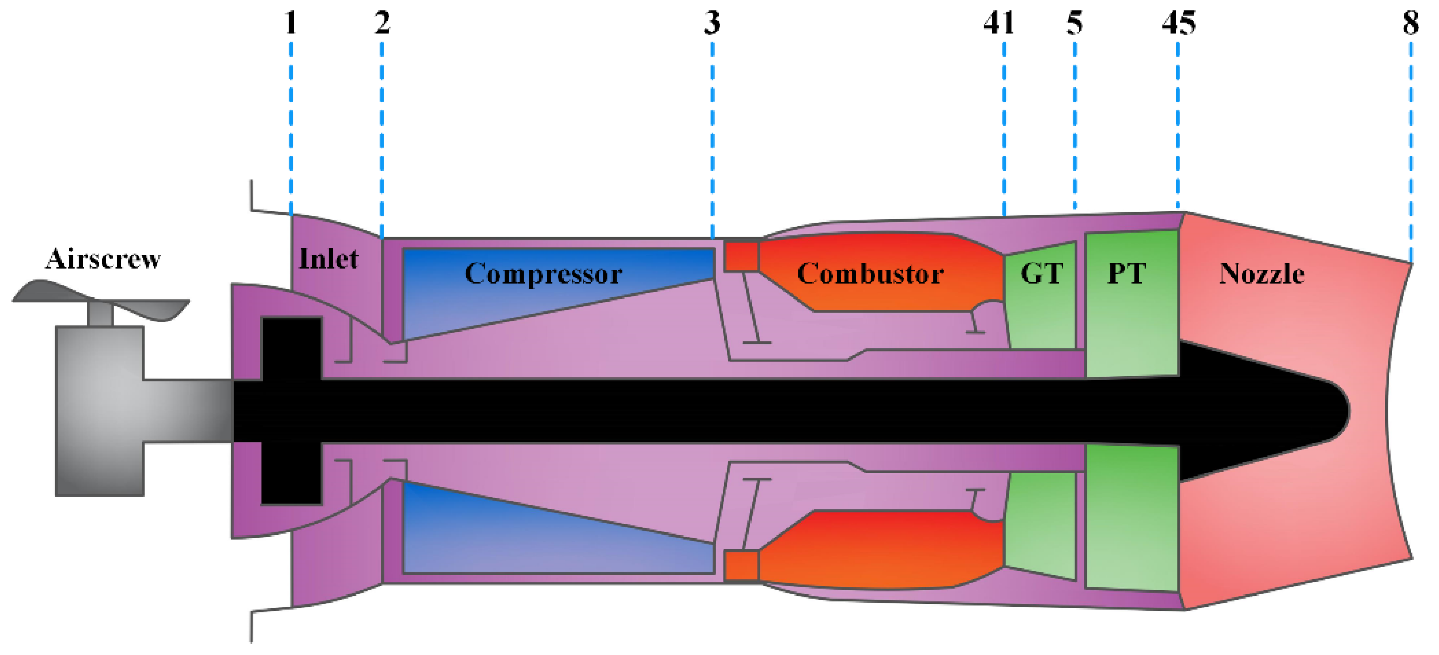
2. Turboshaft Engine Component Level Model

The structure and section definition of the turboshaft engine model established in this paper are shown in Figure 1 and the numbers such as 1,2,3, etc. represent the inlet or outlet sections of different parts of the engine. The main components include airscrew, inlet, compressor, combustion chamber, gas turbine, power turbine, and nozzle. Through the aero-dynamic and thermo-dynamic calculation of each component, the parameters such as temperature, pressure, and flow of each section can be obtained. In addition, each component also needs to meet the balance equation of the mass flow or power. Thus, establishing the mathematical model of the engine with the component method includes three aspects: (1) Completing the aero-thermal calculation of each component along the engine intake process; (2) Establishing and solving the balance equation reflecting the common working relationship between the components in the steady-state operation of the engine; (3) Establishing and solving the balance equation reflecting the common working relationship between the components in the transient operation of the engine.
When the engine is working in a steady-state, the power of the rotating parts should be balanced, and the mass flow through each section should meet the continuous condition so that the following five balance equations can be obtained:
(1)
Power balance between compressor and gas turbine:
f 1 = P G T P C / η m c + P e x t 1
where P G T is the gas turbine power, P C is the compressor power, P e x t is the extracted compressor shaft power and η m c is the mechanical efficiency of the compressor shaft.
(2)
Power balance between airscrew and power turbine:
f 2 = P P T P L / η m L 1
where P P T is the power turbine power, P L is the power required by airscrew and η m L is the mechanical efficiency of the power turbine shaft.
(3)
The flow continuity equation of the gas turbine:
f 3 = W g 41 C W g 41 C X W g 41 C X
where W g 41 C is the real gas flow of combustor exit, W g 41 X is the real gas flow calculated according to W g 41 C at the gas turbine inlet.
(4)
The flow continuity equation of the power turbine:
f 4 = W g 45 C W g 45 C X W g 45 C X
where W g 45 C is the real gas flow of gas turbine exit, W g 45 C X is the real gas flow calculated according to W g 45 C at the power turbine inlet.
(5)
The flow continuity equation of the nozzle:
f 5 = W g 8 W g 8 C W g 8
where W g 8 is the gas flow at nozzle inlet, W g 8 C is the nozzle gas flow calculated by the dense flow function.
In steady-state calculation, these five equations are expected to be equal to zero, and the Newton-Raphson (N-R) method shown in Equation (6) is used to solve these five equations. In addition, the relative speed of the compressor N g , the relative speed of power turbine N P , the coefficient of compressor pressure ratio ZC, the coefficient of gas turbine pressure ratio Z G T , the coefficient of power turbine pressure ratio Z P T are chosen as guesses for the five operating equations which will be continuously updated in iterations until f 1 to f 5 are less than 10−5.
{ X = X λ J 1 E J = X E
where X = [ N ¯ g N ¯ P Z C Z G T Z P T ] T is the vector composed of five guesses, E = [ f 1 f 2 f 3 f 4 f 5 ] T is the vector composed of the five errors, λ is the step size, J is the Jacobian matrix of E to X.
In transient calculation, the power of each rotating part has a difference, which makes the engine in a dynamic adjustment state where the rotor is in a power unbalanced state, but the flow of each section is considered continuous, and the pressure of the corresponding section is considered equal, that is, the dynamic point calculation should meet the quasi-balance condition of continuous flow and pressure balance. Therefore, in the dynamic calculation, the rotor dynamics equation shown in Equation (7) is used to replace the power balance equation. After the dynamic point is solved, the rotor dynamics is used to update the rotor speed in each simulation cycle.
{ d N g d t = ( P G T P C / η m g P e x t ) / [ ( π 30 ) 2 N g J G T ] d N p d t = ( P P T P L / η m L ) / [ ( π 30 ) 2 N p J P T ]
where N g is the gas turbine rotor speed, N p is the power turbine rotor speed, J G T and J P T are moments of inertia of gas turbine shaft and power turbine shaft, t is time.

3. Real-Time Surge Model of Turboshaft Engine

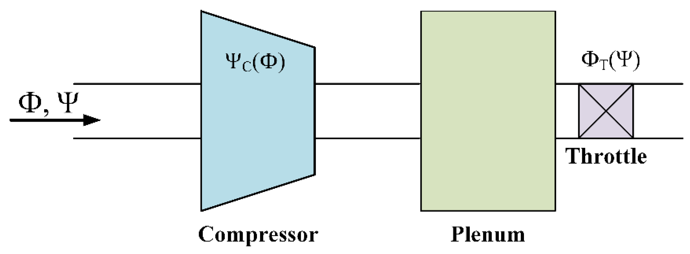
3.1. Classic MG Model

In 1985, based on their theoretical research, Moore and Greitzer collaborated to complete a two-dimensional unsteady incompressible nonlinear model, referred to as the MG model, that described the dynamic process and characteristics of the rotating stall and surge of the compression system as shown in Figure 2. This model is described by the following three mutually coupled differential equations:
d Ψ d ξ = 1 4 B 2 l c ( Φ Φ T ( Ψ ) )
d Φ d ξ = 1 l c ( Ψ c ( Φ ) Ψ 3 H 4 ( Φ W 1 ) J )
d J d ξ = J [ 1 ( Φ W 1 ) 2 J 4 ] δ
where Φ is the flow coefficient in the compressor; Ψ is the pressure-rise coefficient; J is the square of the amplitude of angular disturbance of flow coefficient; ξ is the dimensionless time; H and W are respectively the semi-height and semi-width of cubic axisymmetric characteristic in Figure 3; l c specifies the length of compressor and duct; δ is a constant coefficient that reflects the flow hysteresis in the compression system. B is the well-known Greitzer-B parameter defined as:
B = U 2 a S V p A C l C
where U is the tangential speed of the rotor. a S is the local sound speed; V p is the plenum volume and A C is the cross-section of the compressor.
Ψ c ( Φ ) is the steady-state characteristic curve of the compressor expressed by the following cubic curve function:
Ψ C ( Φ ) = Ψ C 0 + H [ 1 + 3 2 ( Φ W 1 ) 1 2 ( Φ W 1 ) 3 ]
Φ T ( Ψ ) is the throttle valve characteristic which can be expressed by the following equation:
Φ T ( Ψ ) = γ T Ψ
Figure 3 shows the compressor characteristic curve and the throttle valve characteristic line at different throttle valve openings, where points A and B are in the stable state, point C is the surge operating point of the compressor, and points D and E are in an unstable state. When the compressor operating point is located in the positive slope region of its characteristic line, the compressor is in an unstable working state.
Let J = 0 in Equation (10), which represents the disappearance of the airflow disturbance wave at the inlet of the compressor, and the MG model of the second-order pure surge is obtained:
d Φ d ξ = 1 l c ( Ψ c ( Φ ) Ψ )
d Ψ d ξ = 1 4 B 2 l c ( Φ Φ T ( Ψ ) )

3.2. Stability Analysis of MG Model

For a specific MG pure surge model of a compression system, there is a B c r which represents the critical value of B and when the B parameter is less than B c r , the instability type of the MG model is the surge. Additionally, the value of B c r can be obtained with Hopf bifurcation analysis [22,23,24].
Express Equations (14) and (15) in the form of x ˙ = f ( x , B ) where x = [ Φ Ψ ] T and suppose the equilibrium point of the system is ( Φ 0 , Ψ 0 ) , then the Jacobian matrix is obtained:
L = D x f ( Φ 0 , Ψ 0 ) = [ f 1 Φ f 1 Ψ f 2 Φ f 2 Ψ ] Φ = Φ 0 , Ψ = Ψ 0 = [ Ψ ˙ c ( Φ 0 ) l c 1 l c 1 4 B 2 l c Φ ˙ T ( Ψ 0 ) 4 B 2 l c ]
The characteristic equation is obtained according to det ( λ I L ) = 0 :
λ 2 + [ l c Φ ˙ T ( Ψ 0 ) 4 B 2 l c Ψ ˙ c ( Φ 0 ) ] 4 B 2 l c 2 λ + 1 Ψ ˙ c ( Φ 0 ) Φ ˙ T ( Ψ 0 ) 4 B 2 l c 2 = 0
where Φ ˙ T ( Ψ 0 ) and Ψ ˙ c ( Φ 0 ) are respectively the characteristic derivatives of throttle valve and compressor at the equilibrium point:
Φ ˙ T ( Ψ 0 ) = γ T 2 Ψ 0
Ψ ˙ c ( Φ 0 ) = 3 H 2 W ( 1 ( Φ 0 W 1 ) 2 )
The change of the real part of the eigenvalue of the matrix determines the number of special structures in the phase space and the properties of each of them. Considering MG model with H = 0.18, W = 0.25, γ T = 0.55, the compressor characteristic parameters H, W and γ T keep unchanged to analyze the distribution of eigenvalue of the Jacobian matrix with different B parameters. The changing trajectory of the two eigenvalues with the B parameter is shown in Figure 4. With the increase of the B parameter, the distribution of the two eigenvalues goes through three stages: two negative real eigenvalues, a pair of conjugate complex eigenvalues and two positive real eigenvalues. In the second stage, the pair of common complex eigenvalues cross the imaginary axis from the left half complex plane to the right half complex plane. When crossing the imaginary axis, the real part of the common eigenvalue becomes zero, which means the stability of the equilibrium point changes and a limit cycle is generated at the equilibrium point. When B = 0.4404, the real part of the two eigenvalues is 0 and Hopf bifurcation occurs. Therefore, the B c r of MG model, in this case, is 0.4404.
The classical MG model has certain compressor characteristics, that is, H and W are determined, so the throttle opening directly affects the B c r . For the characteristic equation as Equation (17), B c r can be accurately solved by using the Routh Hurwitz criterion [25]. Figure 5 shows the value of B c r under γ T and they are positively correlated. For a given B parameter, the B c r can be reduced by reducing γ T , so that the B parameter that originally made the system stable becomes greater than B c r , making the model enter or exit surge.
Use Matcont toolbox [26] to further analyze the change of limit cycle with B parameter during the surge, and the results are shown in Figure 6. When the B parameter is greater than the B c r , the limit cycle occurs and its size is related to the size of the B parameter. With the increase of the B parameter, the limit cycle increases rapidly, then decreases slowly in the direction of pressure rise coefficient, and the direction of flow coefficient tends to be stable. When the B parameter is large, the mass flow coefficient is smaller than 0, which means that backflow occurs and the model enters a deep surge.
Based on the above analysis, Bcr is determined by the compressor characteristics and the throttle opening: if the throttle opening is reduced, B decreases, and if the throttle opening is increased, B increases accordingly. When the B parameter is greater than B c r , the MG model surges meanwhile Φ and Ψ pulsate, and the larger the B parameter, the larger the pulsation amplitude, the lower the pulsation frequency. Therefore, the process of MG model’s stable state—surge state—stable state in and retreating can be simulated by the following steps:
Step 1. Set the initial B parameters and throttle valve opening, run the MG model.
Step 2. Decrease the throttle opening γ T so that B c r < B , MG model goes into surge state.
Step 3. Adjust the B parameter to simulate different pulsation amplitudes and frequencies.
Step 4. Increase the throttle opening γ T so that B c r > B , MG model return to the stable state.

3.3. Extended MG Model

In the CLM, the compressor component characteristics are obtained by the compressor test-bed and expressed as three-dimensional tables of speed, pressure ratio and flow for interpolation during calculation, so that CLM can simulate the stable operation state and acceleration or deceleration dynamic process at different rotor speeds. The classic MG model describes the instability of the compressor at a certain constant rotor speed, so only one axisymmetric curve is used to describe the characteristics of the compressor. However, in fact, the compressor characteristic varies with the rotor speed, and it is generally can be expressed as a cluster of iso-speed lines. Therefore, it is necessary to expand the characteristics of the MG model to match the compressor characteristics in the CLM, but it should be noted that the parameters in the CLM are dimensional, while the parameters in the MG model are dimensionless. The specific conversion method will be introduced in the next section. According to [27], considering the influence of the rotor speed on compressor characteristics, Equation (20) is used to fit the compressor’s full flow characteristics. When the rotor speed increases, the values of H and W increase, otherwise decrease, which means that the iso-speed line characteristic line is almost in parallel and the characteristic line moves higher when the rotor speed increases, and vice versa. The actual expanded compressor characteristics are shown in Figure 7 where each curve in the figure represents the functional relationship between the pressure rise coefficient and the flow coefficient at a certain rotor speed. In the calculation of the MG model, different compressor characteristic lines are called according to the rotor speed interpolation, so that the model can reflect the surge dynamic process with different characteristics.
{ Ψ C ( Φ ) = Ψ C 0 + H [ 1 + 3 2 ( Φ W 1 ) 1 2 ( Φ W 1 ) 3 ] , Φ > 0 Ψ C ( Φ ) = Ψ C 0 + H ( Φ 2 W ) 2 , Φ < 0

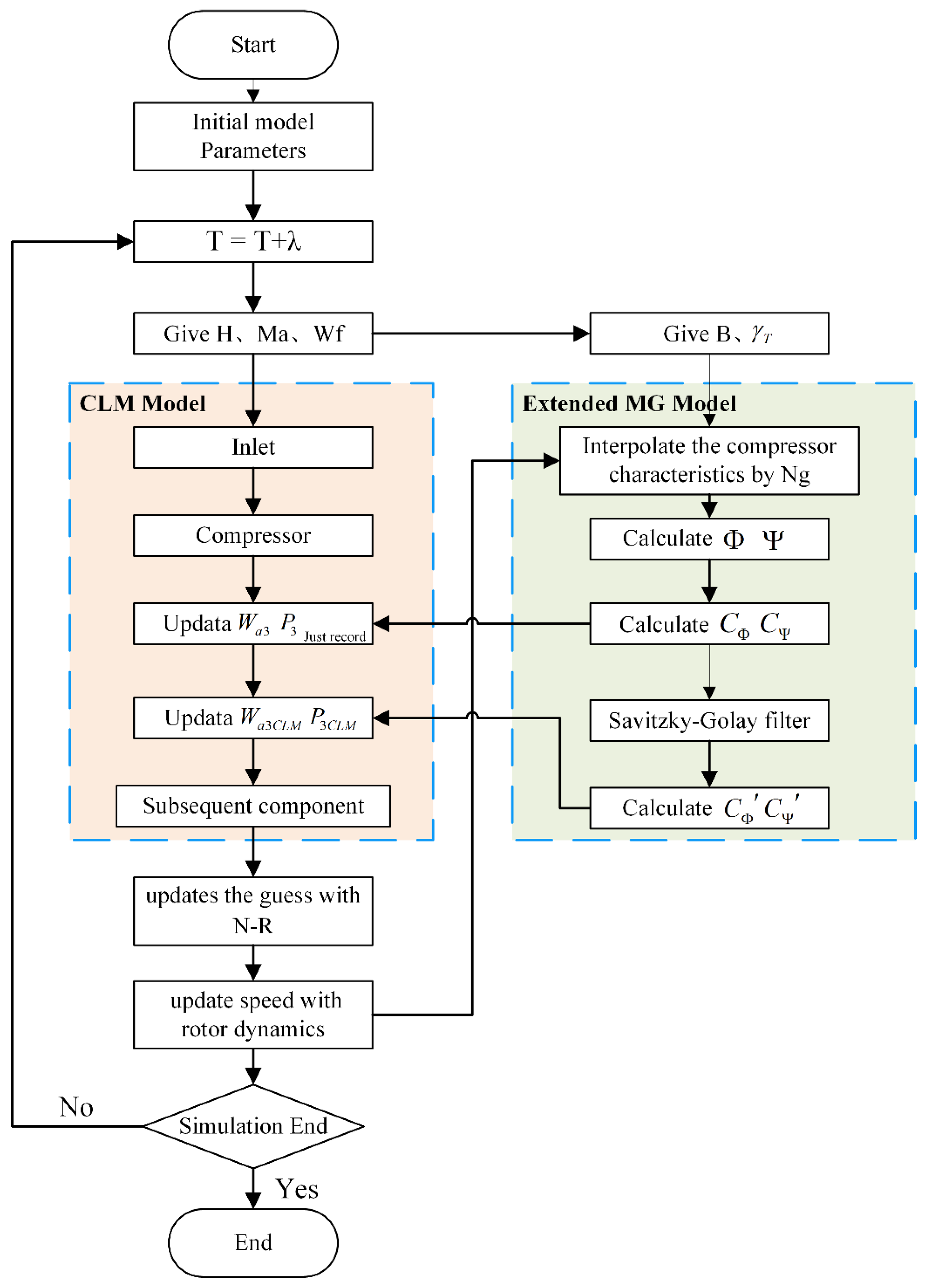
3.4. Coupling Relationship between Extended MG Model and CLM

The extended MG model well describes the dynamic process of the compressor instability at different rotor speeds, while the CLM can simulate the overall aero-thermal parameters of the dynamic process of the whole engine. Therefore, it is considered to establish a connection between the two models, and transfer the compressor surge characteristics to the CLM to realize the simulation of the whole engine surge behavior.
In the extended MG model, the mass flow, pressure, and time are dimensionless as follows:
{ Φ = W a 3 ρ A C U Ψ = P 3 P 2 ρ U 2 ξ = U R t
Therefore, the relationship between the pressure coefficient, the flow coefficient and the actual parameters of the compressor components can be derived according to Equation (22):
{ W a 3 = Φ ρ A C U P 3 = P 2 + Ψ ρ U 2
It is obvious that the flow coefficient Φ and the pressure coefficient Ψ calculated by the extended MG model are linearly related to the compressor’s actual mass flow W a 3 C L M and pressure P 3 C L M , thus the change of the pressure rise coefficient and the flow coefficient in the surge dynamic process and the change of the actual outlet pressure and flow of the compressor must be consistent. Normalize Φ and Ψ as in Equation (23) to obtain the flow instability coefficient C Φ and the pressure rise instability coefficient CΨ, which describe the changes in Φ and Ψ compared to the steady operation when the surge occurs. Finally, the compressor outlet pressure and flow under surge conditions, W a 3 and P 3 can be obtained in Equation (24) and the surge process of the extended MG model is mapped to the component-level model.
{ C Φ = Φ Φ 0 C Ψ = Ψ Ψ 0
{ W a 3 = C Φ W a 3 P 3 = C Ψ P 3
It should be noted that when the surge occurs in the engine, although the compressor outlet parameters show a large low-frequency pulsation, considering the overall rotor inertia and thermal inertia of the engine, the performance parameters such as speed and exhaust temperature do not follow the pulsation, but show a slow downward trend. After W a 3 and P 3 being calculated, if the pulsating flow and pressure are directly substituted into the components and subsequent components calculation of CLM, the characteristics of performance parameters such as speed and exhaust gas temperature will also show pulsation, which is not consistent with the actual surge process.
Therefore, after the W a 3 and P 3 are calculated, they are just recorded as the mass flow and pressure at the compressor outlet, but not substituted into the subsequent calculations in CLM. Instead, the Savitzky-Golay smoothing filter is used to C Φ and C Ψ to get C Φ and C Ψ in Figure 8, and then calculate the actual outlet mass flow W a 3 C L M and pressure P 3 C L M of the compressor in CLM again which will be substituted into the subsequent calculation of CLM.
As the engine goes through the process of stable—surge—stable, the mass flow and pressure after filtering show a slow downward trend and will slowly return to the original level before the surge when the stability is recovered, which is in line with the characteristics of the slow change of the engine performance parameters during the actual whole engine surge process.
In summary, the structure of the turboshaft engine real-time surge model based on the surge mechanism model is shown in Figure 9, including two parts: the component-level model and the extended MG model. The dynamic process of compressor surge is simulated by adjusting the B parameter and the throttle opening in the extended MG model. After that, the flow coefficient and pressure rise coefficient calculated by the MG model are normalized and averaged by Savitzky-Golay smoothing filter, and then updated to the compressor outlet parameters in the CLM. Finally, the subsequent CLM calculations are completed to complete the simulation of the entire engine surge dynamic process.

4. Simulation and Verification

The parameters of the extended MG model used in the simulation are shown in Table 1. The real-time surge model in this paper is implemented in C++ and the running environment is i5-9400 CPU, 8 GB RAM and Windows 10 operating system. It should be noted that the surge model is developed from the turboshaft engine component level model (CLM) with 20 milliseconds as the calculation step, whose real-time performance has been widely verified in engineering [28]. The extended MG model and the coupling relationship are calculated by defining a function in C++, which does not significantly increase the amount of calculation and has little impact on the real-time performance.

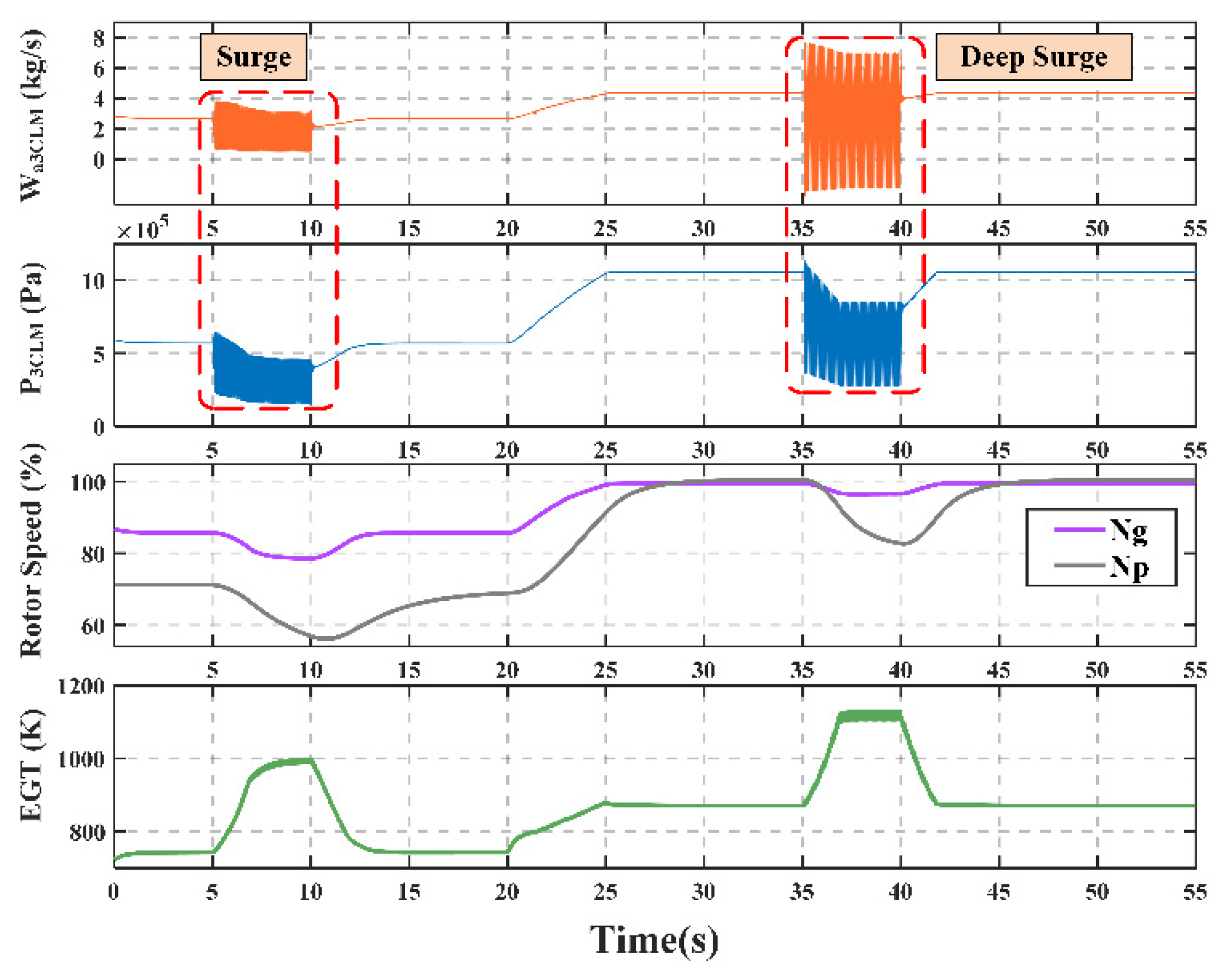
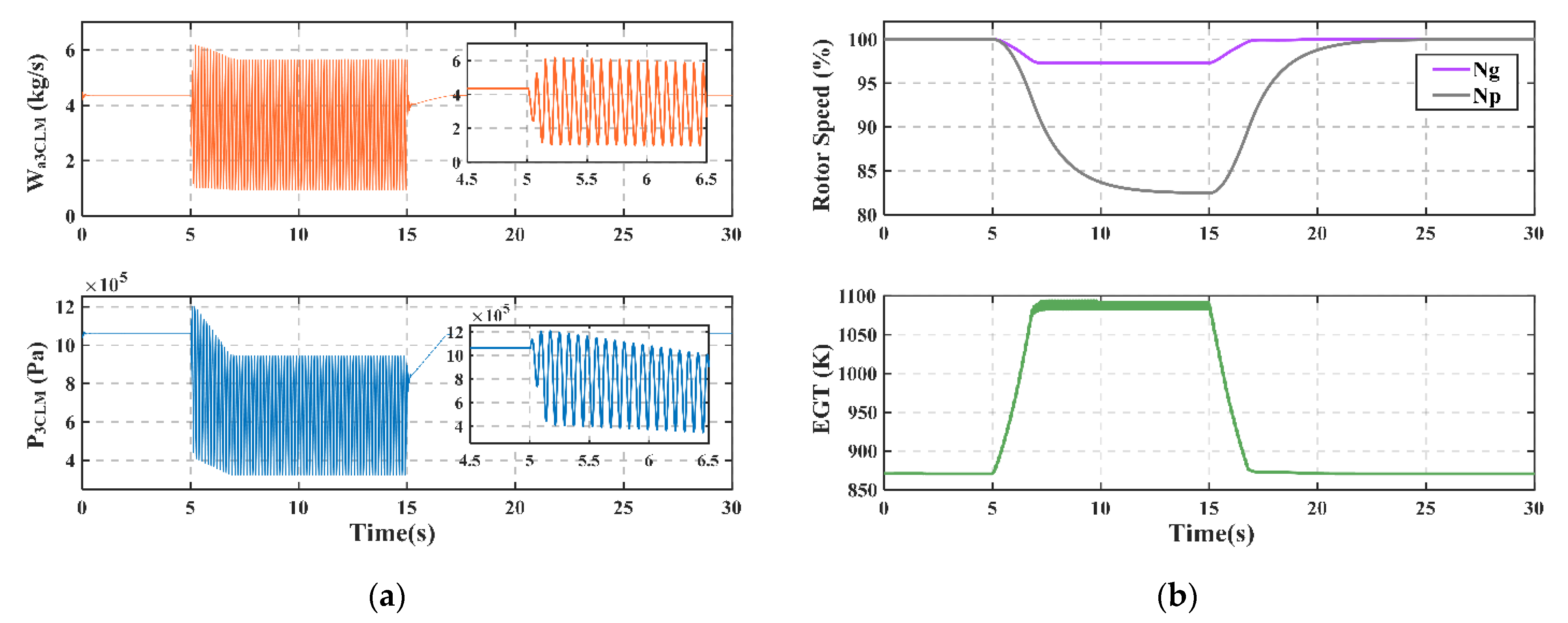
4.1. Surge Dynamic Process Simulation at the Design Point

Step 1. Give the model input. (Altitude: H = 0 km, Mach number: Ma = 0, Fuel: W f = 0.092556, B = 0.6, γ T = 0.65)
Step 2. The γ T is decreased from 0.65 to 0.55 at t = 5 s, which makes the model into surge;
Step 3. The γ T is increased from 0.55 to 0.65 at t = 15 s, which makes the model out of surge.
During the surge process, the model’s compressor outlet mass flow, pressure, rotor speed and exhaust gas temperature are shown in Figure 10. It can be seen that the turboshaft engine model enters into the surge at t = 5 s meanwhile the compressor outlet mass flow and pressure signal of the model represent the typical characteristics of low-frequency and large-scale pulsation during the surge. Besides, the overall performance parameters of the engine show a gradual decrease in speed and a gradual increase in exhaust temperature, which shows that the model successfully reflects the rotor inertia and thermal inertia of the turboshaft engine. When the model returns to the stable state at t = 15 s, each parameter gradually returns to the level during normal operation. Comparing the changes in rotor speed, compressor outlet pressure, and exhaust temperature given by the actual test data in [2] shown in Figure 11, after the model in this paper into the surge, the macro change characteristics of the parameters of the model are consistent with the test data.
Fast Fourier transform is performed on the compressor outlet pressure signal, and its frequency component is analyzed as shown in Figure 12. Its main frequency component is 12.0977 Hz, which conforms to the pressure pulsation law of 0~15 Hz in [4] when the real turboshaft engine goes into surge.

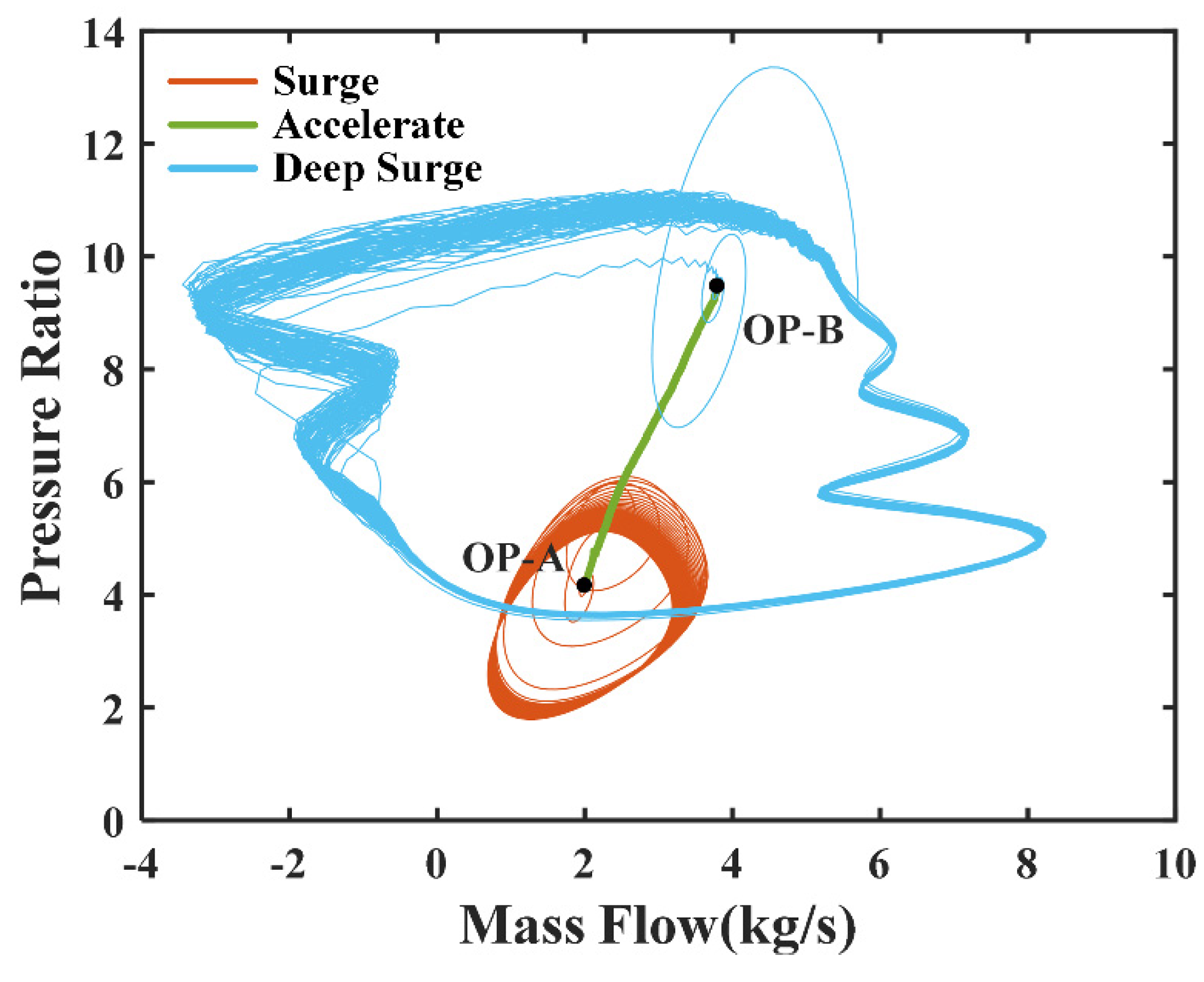
4.2. Surge Dynamic Process Simulation at Multiple Operating Points

In order to verify the ability of the turboshaft engine surge model to simulate the surge at multiple operating points, set the model to simulate the surge process of accelerating from 85% Ng speed to 100% Ng speed:
Step 1. Give the model input and make the engine operate stably at 85% Ng speed. (Altitude: H = 3 km, Mach number: Ma = 0.6, Fuel: W f = 0.07, B = 0.6, γ T = 0.65)
Step 2. Decrease the throttle valve opening γ T to 0.55 to make the model go into surge at t = 5 s.
Step 3. Increase the throttle valve opening γ T to 0.65 to make the model out of the surge at t = 10 s.
Step 4. Increase the W f to 0.092556 at t = 20 s to make the engine accelerate to 100% Ng speed.
Step 5. Increase the B parameter to 2, and decrease the throttle valve opening to 0.55 at t = 35 s, which makes the model into deep surge again.
Step 6. Increase the throttle valve opening to 0.8 finally and the engine returns to the stable state.
After performing the above steps, the process of the whole engine’s surge, acceleration, deep surge, and recovery of stability was successfully simulated. The changes of Np, Ng, compressor outlet pressure, mass flow, and EGT during the entire simulation process are shown in Figure 13 and the engine’s operating trajectory is shown in Figure 14. Firstly, the engine operates stably at 85% Ng speed, corresponding to operating point A (OP-A). A classical surge occurs when t = 5 s and the operating point trajectory presents a small limit cycle. After exiting the surge, the engine accelerated from OP-A to OP-B at 100% Ng speed, and then a deep surge occurs at t = 35 s. The deep surge corresponds to a larger limit cycle, which indicates that there is a greater fluctuation in pressure and flow. In addition, at this time, the mass flow of the compressor is less than 0, which indicates that backflow has occurred inside. Finally, the engine returns stable after t = 40 s, and all performance parameters return to the normal level. In the whole simulation process, the operating trajectory of the engine presents two oscillation rings and a straight line, corresponding to two surge processes and the acceleration processes respectively.

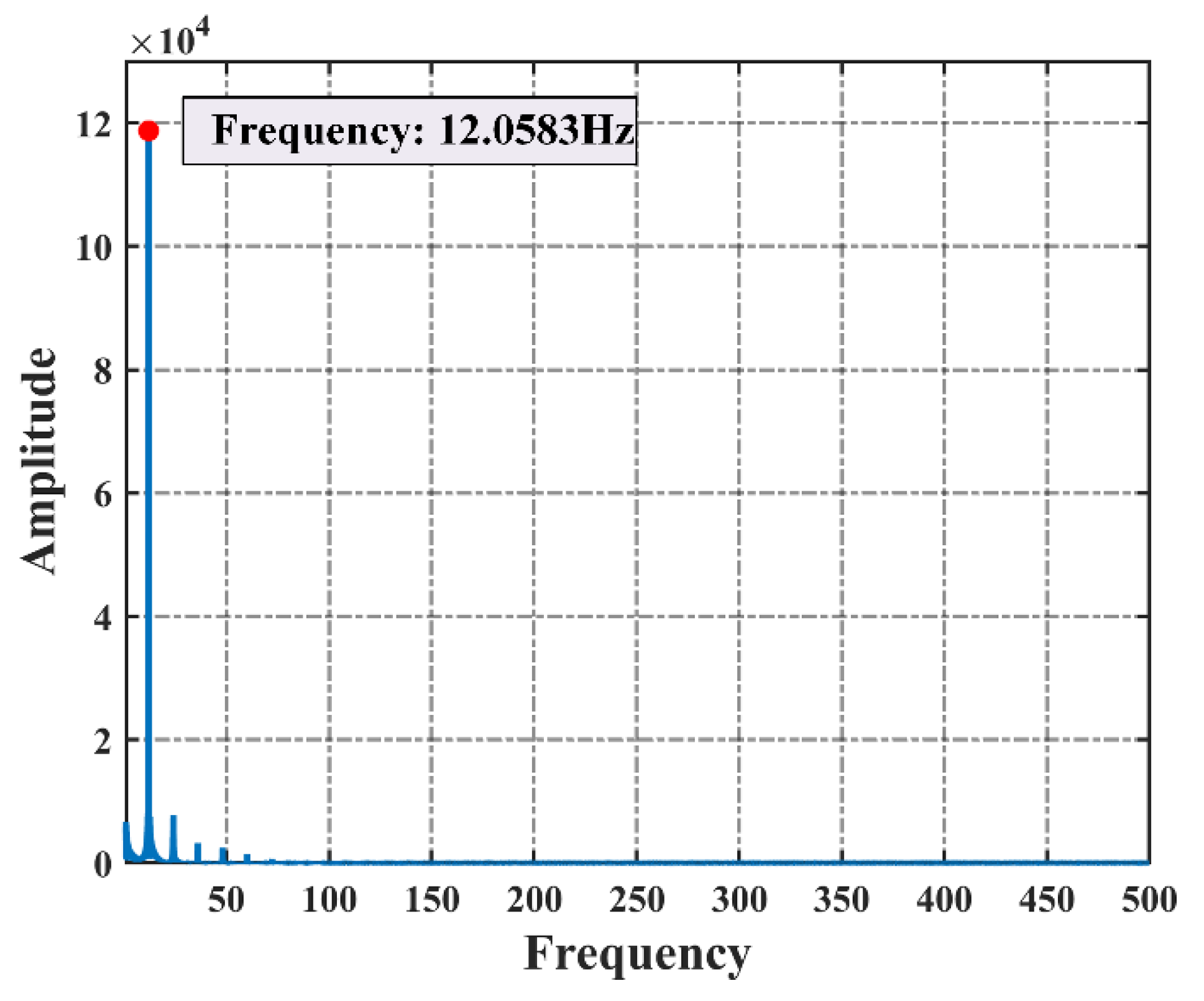
4.3. Model Confidence Verification

In order to further verify the confidence of the simulated surge signal, the aero-engine surge detection method in [29], which has benefitted dozens of core engine surge tests, is applied to the surge real-time model in this paper.
The main steps of the aero-engine surge detection method based on fluctuating pressure change rate are as follows
Step 1. Use Butterworth filter for dynamic pressure low-pass filtering and reserve the pressure component below 150 Hz.
Step 2. Remove the steady-state pressure component P ¯ 3 C L M and extract the pulsating pressure component Δ P 3 C L M . The steady-state pressure component is calculated by the front-end point moving average method:
P ¯ 3 C L M = 1 N i = 1 N P 3 C L M ( k + i ) , ( k = 1 , 2 , , n )
Δ P 3 C L M ( k ) = P 3 C L M ( k ) P ¯ 3 C L M ( k )
where N is the size of the sliding window and n is the length of the signal sequence.
Step 3. Take the engine control cycle, i.e., 20 ms, as the calculation cycle and calculated | Δ P 3 C L M | which is the absolute value of the pulsating pressure change rate.
Step 4. Detect the | Δ P 3 C L M | and judge whether it exceeds the detection threshold.
Step 5. If | Δ P 3 C L M | is greater than the detection threshold for two times or more in three consecutive detection cycles, it is determined that the engine is surging and a surge alarm signal is sent.
In order to simulate the compressor outlet static pressure signal collected in the real operating environment, white noise with a signal-to-noise ratio of 20 is added to the compressor outlet pressure signal in the multi surge dynamic process in Section 4.2. Using the above surge detection algorithm, the steady-state pressure component P ¯ 3 C L M and the pulsating pressure component Δ P 3 C L M are shown in Figure 15. Obviously, with the occurrence of the surge, the amplitude of fluctuating pressure component increases and the amplitude of the deep surge is greater than that of the classical surge.
As shown in Figure 16, the change rate of pulsating pressure component is further obtained, and the surge detection results are given in combination with the threshold. In Section 4.2, set the model to generate two surges, one for classical surge and one for deep surge and the | Δ P 3 C L M | increases greatly during the surge. According to the simulation settings in Section 4.2 and the detection results of engine surge, the dynamic pressure at the compressor outlet begins to fluctuate and the first surge occurred at t = 5 s. The surge alarm signal appears at 5.08 s while the absolute value of fluctuating pressure change rate sharply increases to 15,000 kPa/s. The surge alarm signal is sent about 0.08 s after the pressure begins to fluctuate. When t = 10 s, the dynamic pressure fluctuation at the compressor outlet ends. The surge alarm signal disappears in 10.04 s, and the surge disappears in about 0.04 s after the pressure fluctuation ends. The second surge occurred at t = 35 s (after accelerating to 100% Ng speed), the dynamic pressure at the compressor outlet begins to fluctuate and the surge alarm signal appears at t = 35.10 s where the absolute value of the fluctuation pressure change rate increased sharply to 30,000 kPa/s. The surge alarm signal is sent out about 0.10 s after the pressure begins to fluctuate. After the dynamic pressure fluctuation at the compressor outlet ends at 40 s, the surge alarm signal disappears at 40.06 s.
The above analysis shows that the time of two surges detected by the surge detection algorithm is the same as the time of entering and exiting surge set by the model, which confirms that the surge process simulated by the turboshaft engine surge real-time model established in this paper is consistent with the characteristics of parameter changes in the actual engine surge process. Therefore, using this model to verify the surge detection algorithm is considered feasible without relying on the high-risk and high-cost engine forced surge test, which is of great significance to the subsequent surge detection and anti-surge control algorithm simulation and development.

5. Conclusions

In this paper, a novel real-time model of turboshaft engine with surge process based on instability mechanism is proposed. The CLM of a turboshaft engine and the extended MG model are established. Then the surge characteristic is embedded into CLM via regarding the compression system described by the MG model as the compressor component in the CLM. On this basis, a real-time surge model of turboshaft engine is proposed by building up a coupling relationship of compressor speed, flow, and pressure between the extended MG model and CLM. The main conclusions are as follows:
(1)
Stability analysis and characteristic line extension of classical MG model are carried out to establish the extended MG model which can be matched with CLM.
(2)
The influence of engine rotor inertia and thermal inertia are considered when establishing the coupling relationship between compressor speed, flow and pressure. The fluctuating flow and pressure are carried into the component level model after the smoothing filter, which can ensure that the change of speed and temperature is in accordance with actual test conditions.
(3)
The real-time surge model proposed combines the extended MG model’s ability to simulate the dynamic process of compressor surge with CLM’s ability to simulate full envelope steady-state and dynamic process to realize the simulation of the whole engine surge process.
(4)
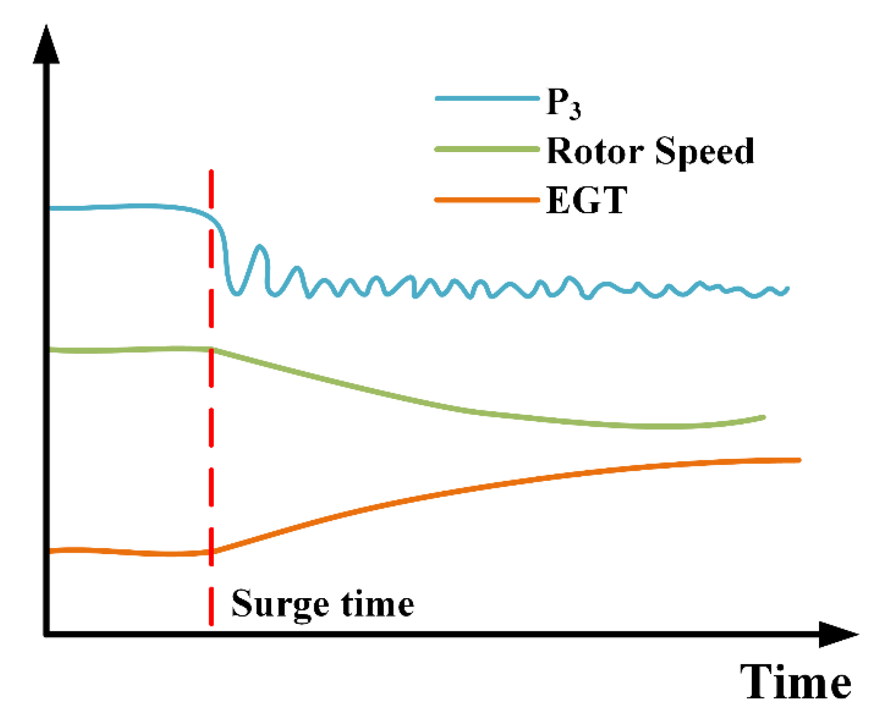
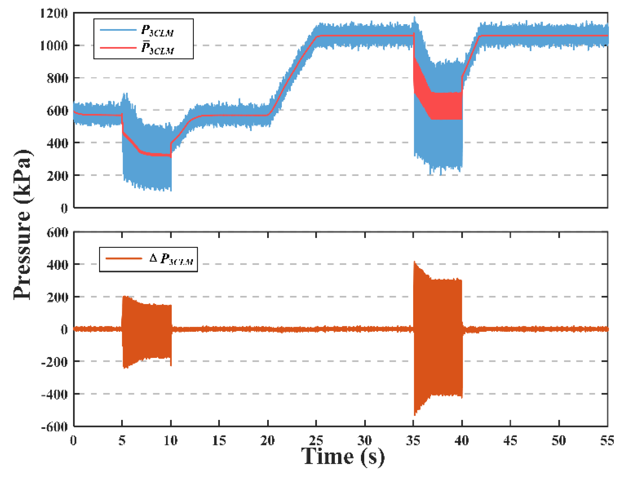
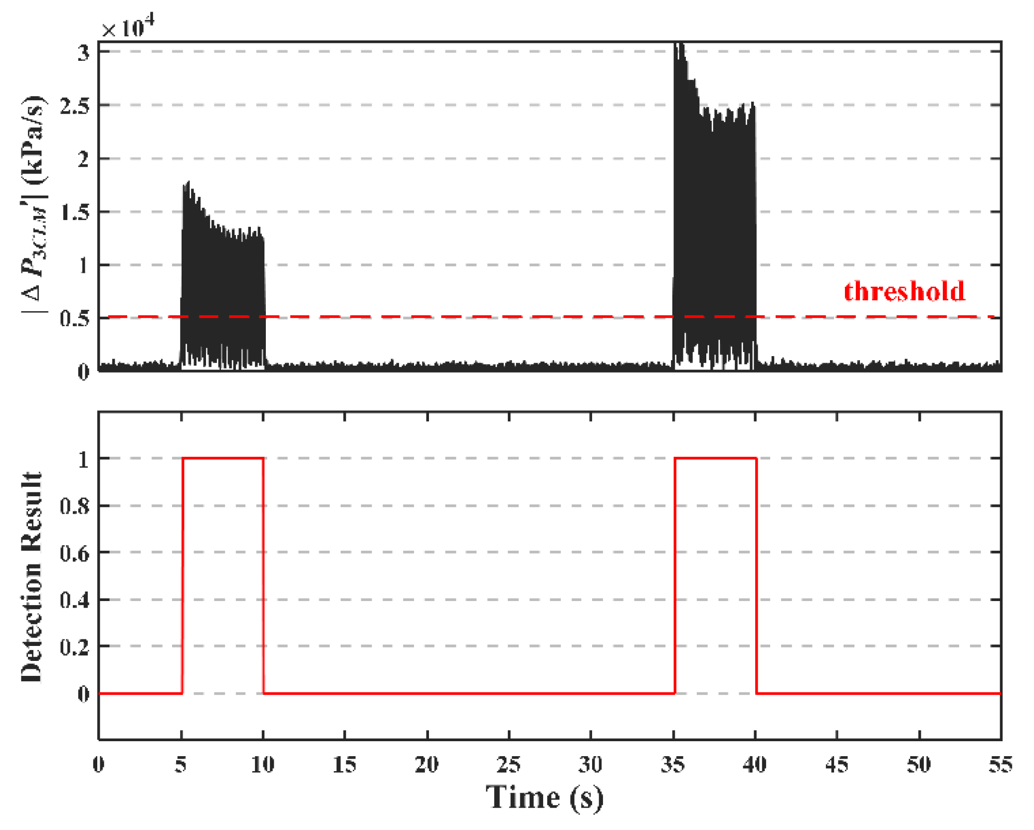
The aero-engine surge detection method [29] which has benefitted dozens of core engine surge tests is applied to the real-time surge model to verify the confidence of the simulated surge signal.
(5)
The modeling methods can be extended to other kinds of aeroengine to provide the model basis for surge detection and anti-surge control to avoid high risk and cost surge tests, so it has important practical significance for the development of active stability control.

Author Contributions

Conceptualization, T.Z.; methodology, X.Z.; programming, X.Z.; validation, X.Z. and L.L.; visualization, L.L.; writing—original draft preparation, X.Z.; writing—review and editing, T.Z. supervision, T.Z.; funding acquisition, T.Z. All authors have read and agreed to the published version of the manuscript.

Funding

This research was funded by National Natural Science Foundation of China, grant number 51976089.

Institutional Review Board Statement

Not applicable.

Informed Consent Statement

Not applicable.

Data Availability Statement

The data presented in this study are available on request from the corresponding author.

Conflicts of Interest

The authors declare no conflict of interest.

References

  1. Hu, J. Aviation Compressor Aerodynamic Stability Analysis Methods, 1st ed.; Natlona1 Defense Industry Press: Beijing, China, 2015; pp. 2–8. ISBN 978-7-118-10164-5. [Google Scholar]
  2. Wang, Y.D. Surge detection method based on rate of change of compressor discharge static pressure. J. Aerosp. Power 2020, 35, 1131–1138. [Google Scholar] [CrossRef]
  3. Kan, Y.X. Research on the VSV Regulation Law and Surge Fault Diagnosis in Civil Aviation Engine. Master’s Thesis, Civil Aviation University of China, Tianjing, China, 2018. [Google Scholar]
  4. Shan, X.M. Research on Flow Instabilities Online Monitoring & Stabilization Enhancement Technology in Turboshaft Engine Compressors. Ph.D. Thesis, Nanjing University of Aeronautics and Astronautics, Nanjing, China, 2012. [Google Scholar]
  5. Kim, K.H.; Fleeter, S. Compressor unsteady aerodynamic response to rotating stall and surge excitations. J. Propuls. Power 1994, 10, 698–708. [Google Scholar] [CrossRef]
  6. Greitzer, E.M. Surge and rotating stall in axial flow compressors—Part I: Theoretical compression system model. J. Eng. Power. 1976, 98, 190–198. [Google Scholar] [CrossRef]
  7. Moore, F.K. A theory of rotating stall of multistage axial compressors: Part I—Small Disturbances. J. Eng. Gas Turbines Power 1983, 106, 190–198. [Google Scholar] [CrossRef]
  8. Moore, F.K.; Greitzer, E.M. A Theory of post-stall transients in axial compression systems: Part I—Development of Equations. J. Eng. Gas Turbines Power 1986, 108, 68–76. [Google Scholar] [CrossRef]
  9. Wang, H.O.; Adomaitis, R.A.; Abed, E.H. Nonlinear analysis and control of rotating stall in axial flow compressors. In Proceedings of the 1994 American Control Conference, Baltimore, MD, USA, 29 June–1 July 1994; pp. 2317–2321. [Google Scholar]
  10. Haynes, J.M.; Hendricks, G.J.; Epstein, A.H. Active stabilization of rotating stall in a three-stage axial compressor. J. Turbomach. 1994, 116, 226–239. [Google Scholar] [CrossRef]
  11. Gravdahl, J.T.; Egeland, O. A Moore-Greitzer axial compressor model with spool dynamics. In Proceedings of the 36th IEEE Conference on Decision and Control, San Diego, CA, USA, 12 December 1997; pp. 4714–4719. [Google Scholar]
  12. Botros, K.K. Transient phenomena in compressor stations during surge. J. Eng. Gas Turbines Power 1994, 116, 133–142. [Google Scholar] [CrossRef]
  13. Hynes, T.; Greitzer, E. A method for assessing effects of circumferential flow distortion on compressor stability. J. Turbomach. 1987, 109, 371–379. [Google Scholar] [CrossRef]
  14. Hu, J.; Fottner, L. A new simplified model of post stall transients in axial compression systems. J. Therm. Sci. 1999, 8, 176–189. [Google Scholar] [CrossRef]
  15. Mansoux, C.A.; Gysling, D.L.; Setiawan, J.D.; Paduano, J.D. Distributed nonlinear modeling and stability analysis of axial compressor stall and surge. In Proceedings of the 1994 American Control Conference, Baltimore, MD, USA, 29 June–1 July 1994; pp. 2305–2316. [Google Scholar]
  16. Bonnaure, L.P. Modelling High Speed Multistage Compressor Stability. Ph.D. Thesis, Massachusetts Institute of Technology, Cambridge, MA, USA, 1991. [Google Scholar]
  17. Feulner, M.R.; Hendricks, G.J.; Paduano, J.D. Modeling for control of rotating stall in high speed multi-stage axial compressors. In Proceedings of the ASME 1994 International Gas Turbine and Aeroengine Congress and Exposition, The Hague, The Netherlands, 13–16 June 1994. [Google Scholar]
  18. Hendricks, G.J.; Sabnis, J.S.; Feulner, M.R. Analysis of instability inception in high-speed multistage axial-flow compressors. J. Turbomach. 1997, 119, 714–722. [Google Scholar] [CrossRef]
  19. Chung, K.; Leamy, K.; Collins, T. A turbine engine aerodynamic model for in-stall transient simulation. In Proceedings of the 21st Joint Propulsion Conference, Monterey, CA, USA, 8–11 June 1985; p. 1429. [Google Scholar]
  20. Hosny, W.; Bitter, S.; Steenken, W. Turbofan-engine nonrecoverable stall computer-simulation development and validation. In Proceedings of the 21st Joint Propulsion Conference, Monterey, CA, USA, 8–10 July 1985. [Google Scholar]
  21. Yang, F.; Hu, J.; Yan, W. Model Research on Post Stall and Recovering from Stall for Aeroengine. Aeroengine 2017, 43, 41–47. [Google Scholar] [CrossRef]
  22. McCaughan, F.E. Application of bifurcation theory to axial flow compressor instability. J. Turbomach. 1989, 111, 426–433. [Google Scholar] [CrossRef]
  23. OuYang, Y.F.; Li, J.L. Study on Monitoring of Compressor Surge Based on the critical B Parameter. Fluid Mach. 2017, 45, 34–37+51. [Google Scholar]
  24. Chen, C.; Nie, C.Q.; Li, J. Nonlinear dynamic analysis on post-stall transients of axial-flow compressor. J. Aerosp. Power 2007, 9, 1461–1467. [Google Scholar]
  25. DeJesus, E.X.; Kaufman, C. Routh-Hurwitz criterion in the examination of eigenvalues of a system of nonlinear ordinary differential equations. Phys. Rev. A 1987, 35, 5288–5290. [Google Scholar] [CrossRef] [PubMed] [Green Version]
  26. Dhooge, A.; Govaerts, W.; Kuznetsov, Y.; Meijer, H.; Sautois, B. New features of the software MatCont for bifurcation analysis of dynamical systems. Math. Comput. Model. Dyn. Syst. 2008, 14, 147–175. [Google Scholar] [CrossRef]
  27. Wang, W.C.; Wang, Y.Y. Establishment of a Dynamic Model for a Compressor and Analysis of the Surge Process. J. Eng. Therm. Energy Power 2007, 22, 124–128+222. [Google Scholar]
  28. Yin, K.; Zhou, W.X.; Qiao, K. Research on Methods of Improving Real-Time Performance for Aero-Engine Component-Level Model. J. Propuls. Technol. 2017, 38, 199–206. [Google Scholar]
  29. Lei, J.; Fang, J.B.; Lei, X.B. Aero-engine surge detection method based on fluctuating pressure change rate. Gas Turbine Exp. Res. 2019, 32, 1–6. [Google Scholar]
Figure 1. The layout of turboshaft engine.
Applsci 12 00744 g001
Figure 2. Schematic diagram of the compression system.
Applsci 12 00744 g002
Figure 3. The characteristic curves of compressor and throttle.
Applsci 12 00744 g003
Figure 4. The Variation of eigenvalue trajectories with B parameter: (a) Variation of two eigenvalues; (b) Variation of real part of two eigenvalues; (c) Variation of imaginary part of two eigenvalues.
Applsci 12 00744 g004
Figure 5. Variation of B c r with γ T .
Applsci 12 00744 g005
Figure 6. The variation of the limit cycle with B parameter: (a) Mass flow instability coefficient; (b) Pressure rise instability coefficient.
Applsci 12 00744 g006
Figure 7. Compressor characteristic curves cluster.
Applsci 12 00744 g007
Figure 8. The effect of Savitzky-Golay smoothing filter: (a) Mass flow instability coefficient; (b) Pressure rise instability coefficient.
Applsci 12 00744 g008
Figure 9. Dynamic calculation of real-time surge model of turboshaft engine.
Applsci 12 00744 g009
Figure 10. Simulation of surge dynamic process at design point: (a) The mass flow and pressure at compressor outlet; (b) Engine’s rotor speed and exhaust temperature.
Applsci 12 00744 g010
Figure 11. Trend of engine’s parameters change in surge test.
Applsci 12 00744 g011
Figure 12. Fast Fourier transform results of P3.
Applsci 12 00744 g012
Figure 13. The changes of engine parameters in the surge dynamic process at multiple operating points.
Applsci 12 00744 g013
Figure 14. The engine’s operating trajectory in the surge dynamic process at multiple operating points.
Applsci 12 00744 g014
Figure 15. The steady-state pressure component P ¯ 3 C L M and the the pulsating pressure component Δ P 3 C L M of simulated pressure P 3 C L M .
Applsci 12 00744 g015
Figure 16. The absolute value of fluctuating pressure change rate ( | Δ P 3 C L M | ) and the surge detection results.
Applsci 12 00744 g016
Table 1. Parameters of the extended MG model.
ParameterValue
Φ 0 0.6
Ψ 0 0.6
l c 2
Ψ C 0 0.3
U Related to Ng in CLM
H Related to Ng in CLM
W Related to Ng in CLM
Publisher’s Note: MDPI stays neutral with regard to jurisdictional claims in published maps and institutional affiliations.

