Article

Research on Key Factors of Sealing Performance of Combined Sealing Ring

1
School of Machinery and Automation, Wuhan University of Science and Technology, Wuhan 430081, China
2
School of Electromechanical and Automobile Engineering, Huanggang Normal University, Huanggang 438000, China
3
Key Laboratory of Metallurgical Equipment and Control Technology, Wuhan University of Science and Technology, Ministry of Education, Wuhan 430081, China
4
Hubei Key Laboratory of Mechanical Transmission and Manufacturing Engineering, Wuhan University of Science and Technology, Wuhan 430081, China
*
Author to whom correspondence should be addressed.
Appl. Sci. 2022, 12(2), 714; https://doi.org/10.3390/app12020714
Submission received: 27 October 2021 / Revised: 23 December 2021 / Accepted: 6 January 2022 / Published: 12 January 2022
(This article belongs to the Special Issue Selected Papers from MMSE 2021)

Abstract

:
In this study, the mechanical properties of a combined seal ring under different loads were numerically calculated using ANSYS. The effect of the working pressure and pre-compression ratio of a rubber O-ring on the contact stress of the combined seal ring was studied. The influence of the wear ring’s chamfer, thickness, and width on the contact stress and contact force of the combined seal ring was analyzed. Studies have shown that it is particularly important to select a compression ratio that is suitable for the working conditions. Under the same conditions of working pressure and compression ratio, upon increasing the wear ring chamfer, the contact pressure is decreased due to the decreasing contact bandwidth between the wear ring and the cylinder wall. This has little effect on the contact stress of the combined seal ring as well as the contact force, while the width of the wear ring is proportional to the latter.

1. Introduction

Sealing performance is one of the most important indicators used to measure the performance of hydraulic cylinders. The main seals used for hydraulic cylinders can be divided into two groups: extrusion seals and gap seals [1]. A squeeze seal means that in the gap of the sealed area, two surfaces are pressed together to prevent the leakage of a fluid medium. The seal will be elastically deformed when it is subjected to pressure so as to close the cover to prevent leakage and achieve a sealing effect [2]. Gap sealing is achieved through a micron-level matching gap between a piston surface and a cylinder wall; the idea is to use the throttling effect of the gap to control leakage [3].
The combined seal ring is a kind of extrusion seal. Combined seals are widely used in hydraulic cylinder piston seals due to their good sealing performance, high pressure resistance, low friction, and high-speed of operation [4,5]. During installation, the O-ring acts on the wear ring through a pre-tightening force produced by radial interference compression deformation, which moves the wear ring close to the cylinder wall, thus achieving the purpose of reducing or preventing fluid leakage [6,7].
Ylinen A et al. [8] structured a simulation model of a complex hydraulic cylinder. He, Q. et al. [9], studied the influence of the contact state of the seal ring and the static pressure mechanical end face sealing performance. S. Mezghani et al. [10] used numerical analysis methods to explore the influence of piston groove structure parameters on lubrication conditions and friction. Staffan Johansson et al. [11] studied the impact of the piston ring surface micro-topography on friction and wear through a hydraulic cylinder in motion tests. Murat Kapsiz et al. [12] and Wieslaw Grabon et al. [13] used the Taguchi method and comparative experiment method to explore the friction and the wear relationship between a piston ring and the cylinder wall of a hydraulic cylinder. Xuan Bo Tran et al. [14] established a hydraulic cylinder dynamic model based on the results of previous research and studied its friction characteristics. Yang, C.Z. et al. [15]; Hingawe et al. [16]; Quan, S. et al. [17]; Shen, C. et al. [18]; and Guo, Z. et al. [19] studied the effect of the pattern and depth of the surface texture of a piston or cylinder on its friction. Studies have shown that the use of reasonable texture patterns and depth helps to reduce the wear between the seal ring and the hydraulic cylinder. By numerical simulations, Chuanxiang Yan et al. [20] investigated the influence of oil temperature on the sealing performance of lip seals. Zhang Jian et al. [21] carried out parameterized modeling of the Glyy ring based on the finite element software Abaqus and explored the factors influencing its sealing performance. Wang Bingqing et al. [22] explored the effect of working pressure, O-ring pre-compression rate, and friction coefficient on a high-pressure star. Brando H.C. et al. [23] investigated the influence of parameters such as the ring gap. Due to extreme pressure conditions, the greatest gas loss in the crankcase occurs during the compression and combustion stages. Flavien Foko et al. [24] studied wear simulation for the radial shaft sealing ring and uncovered a method to calculate the wear rate.
In summary, many researchers have studied the sealing, friction, and wear of reciprocating seals and analyzed the influence of material parameters, working condition parameters, and compressibility on the sealing performance. However, few researchers have designed the structural parameters of a combined seal. Additionally, few researchers have analyzed the key factors affecting the sealing performance of the combined seal ring. In this study, ANSYS was used to analyze the mechanical characteristics of a combined seal ring under a load, the key factors affecting the sealing performance of the combined seal ring were studied, and the influence of the working pressure and the pre-compression rate of the rubber O-ring on the contact stress of the combined seal ring was analyzed. We also analyzed the influence of the chamfer R, thickness H, and width L of the wear ring on the contact stress and contact pressure of the combined seal ring. The analysis results will be perfectly useful for improving the sealing function of the combined sealing ring.

2. Structure Drawing, Material, and Simulation Method of the Combined Sealing Ring

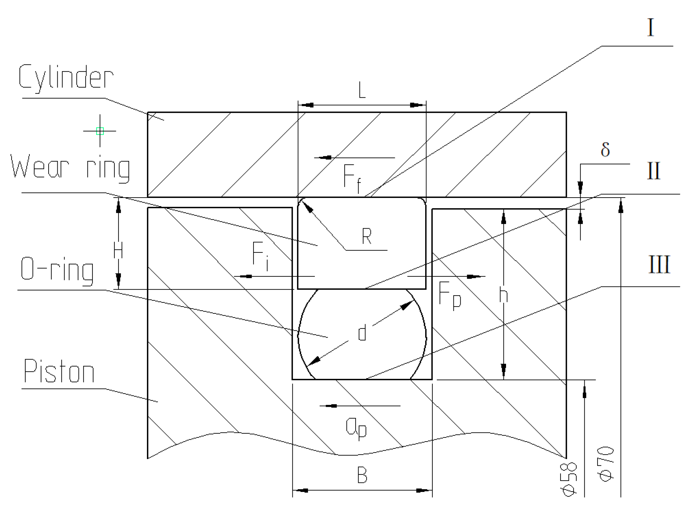
2.1. Assembly Structure Diagram of Combination Seal Ring

A sectional view of the structure of the combined sealing ring is shown in Figure 1. This paper mainly studies the contact stress of the three sealing faces of I, II, and III in the figure and the contact force F at I. The contact stress on contact surface I is integrated along the contact length to obtain the contact force F and the friction force f as follows:
F = 2 π R x 1 x 2 P d x   ( x   is   the   contact   length ,   x 1 = 0 , x 2 = L )
f = μ 1 F
μ 1 —Coefficient of the friction of the inner wall of the cylinder against the wear ring.

2.2. Material Table of Hydraulic Cylinder and Combined Sealing Ring

The analysis model selected was the Mooney–Rivlin model at room temperature, where C 01 = 2.6529 and C 10 = 4.4349 [25]. The coefficients C 01 and C 10 are determined through experiments and used to determine the Mooney–Rivlin material mechanical constants. The material table for the hydraulic cylinder and combined sealing ring is shown in Table 1.
The friction coefficient of steel to PTFE is 0.04 [26], and the friction coefficient of steel to nitrile rubber is 0.75 [27].

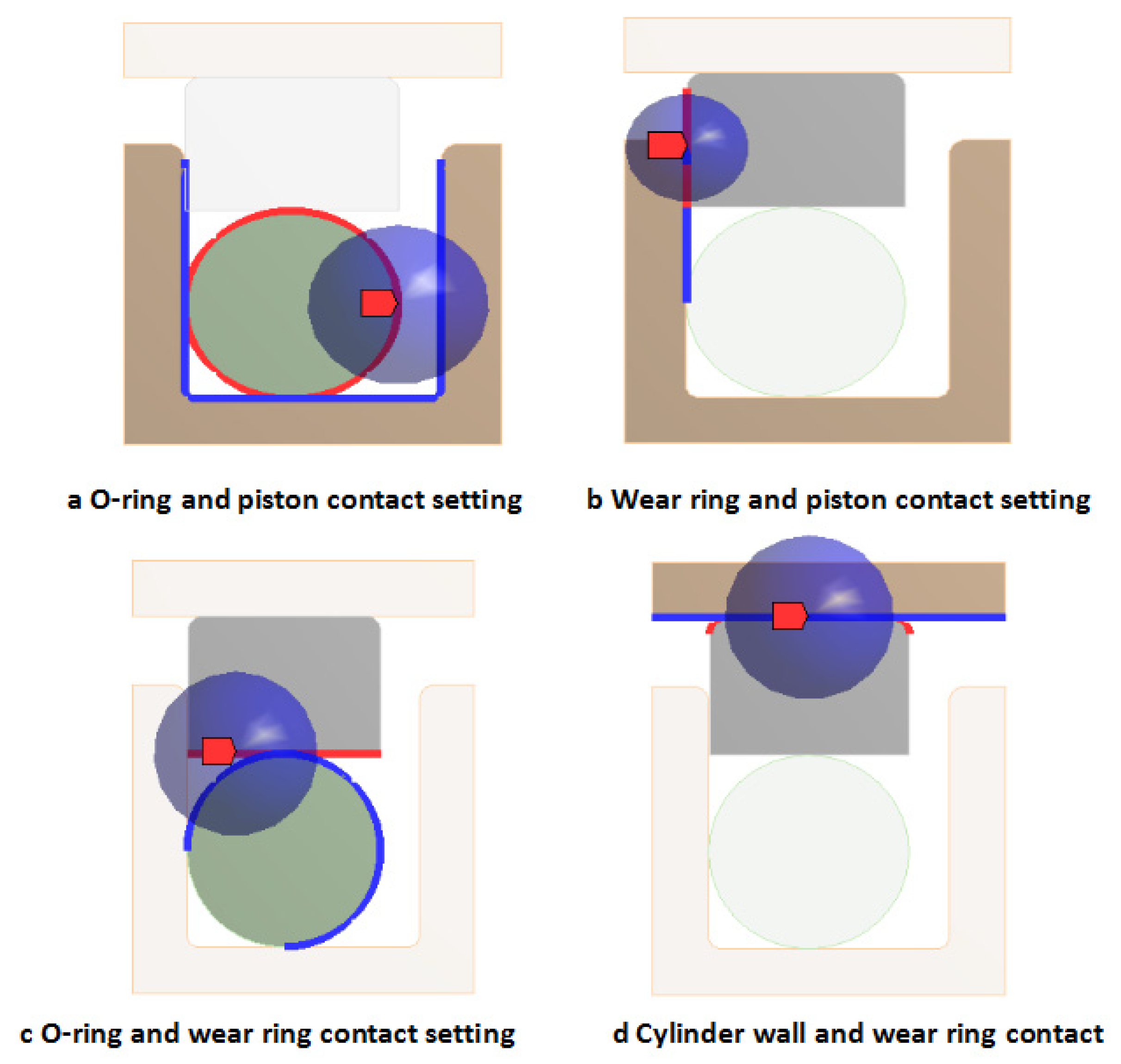
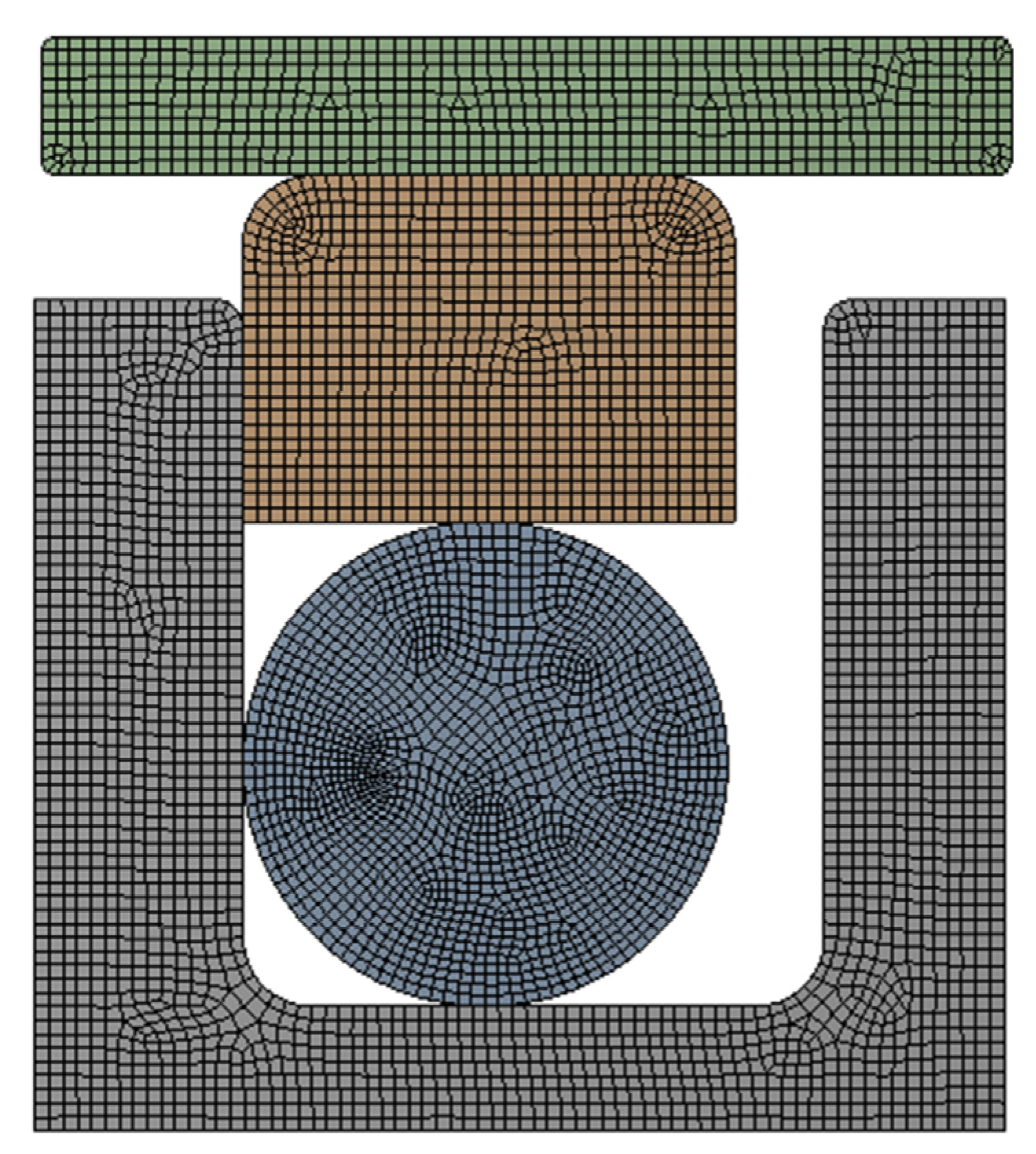
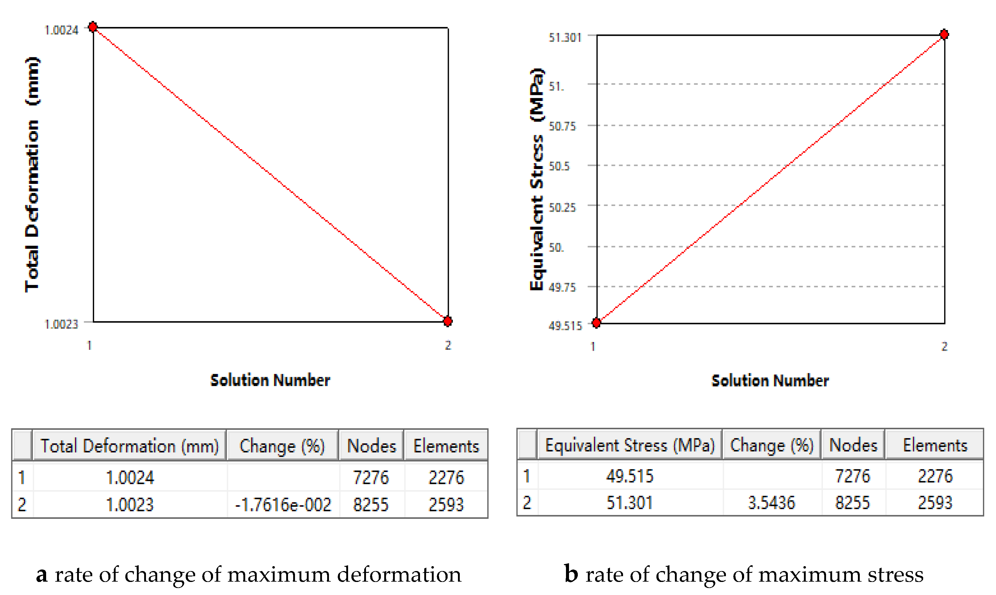
2.3. Define Contact and Meshing

In the combined sealing structure, there are mainly four contact situations including the piston and the O-ring, the piston and the wear ring, the O-ring and the wear ring, and the wear ring and the cylinder wall. In the contact analysis setting, select Frictional or Bonded contact form for contact type, select Asymmetric for contact behavior, select Augmented Lagrange for rubber material advanced, and select On Gauss Point for detection method. The Combination seal ring contact analysis settings are shown in Figure 2.
“Relevance Center-Fine” is selected to refine the nodes and adjust the number of cells, which ensures the smooth transition of each contact element and the better mesh quality of the O-ring. The meshes are all 4-node quadrilateral elements. The grid size of the piston is set to 0.1 mm, the grid size of the O-ring is set to 0.1 mm, the grid size of the wear ring is set to 0.1 mm, the grid size of the cylinder wall is set to 0.1 mm, and the number of nodes is 7276. The combined sealing mesh model is shown in Figure 3.
As shown in Figure 4, Convergence analysis shows that when the nodes of the analyzed body increase by 20%, the change in deformation is 0.017% and the change in stress is 3.5%. The increase of the nodes has very little effect on strain and stress, which can be considered as convergent.

2.4. Boundary Condition Setting and Simulation Method for Combined Sealing Ring

The combined sealing ring and groove were completely symmetrical in structure and were handled according to the two-dimensional axisymmetric problem in finite element modeling. It set the initial boundary conditions, selected the piston ring surface and the cylinder barrel as the fixed surfaces, and added fixed constraints to ensure that the cylinder wall and the piston surface had a sealing gap of 0.4 mm after the installation was complete. As shown in Figure 1, the piston ring surface and the cylinder tube were selected as fixed surfaces, and the gap δ between the cylinder wall and the piston surface was set to 0.4 mm, in which groove depth h and width B were set to 5.1 mm and 4.2 mm, respectively. The width L and the thickness H of the wear ring were set to 3.5 mm and 2.5 mm, respectively, while the O-ring cross-sectional diameter d was set to 3.5 mm and the inner diameter was set to 58 mm.
In order to study the sealing performance of combined seals in medium- and high-pressure situations, under the same structural parameters, the working pressures of P1 = 10 MPa, P2 = 15 MPa, P3 = 20 MPa, and P4 = 25 MPa were compared and analyzed.

3. Analysis and Results

3.1. Effect of Operating Conditions on Sealing Performance

As can be seen from Figure 5, the maximum stress occurs at the position where the wear ring comes into contact with the chamfer of the cylinder wall, at which time the wear ring is sheared. The maximum stress on the combined seal ring is on the seal ring and is proportional to the working pressure. When the working pressure reaches 25 MPa, the maximum stress reaches 49.836 MPa, but this value is still much less than the allowable stress of the material, which is 280 MPa.

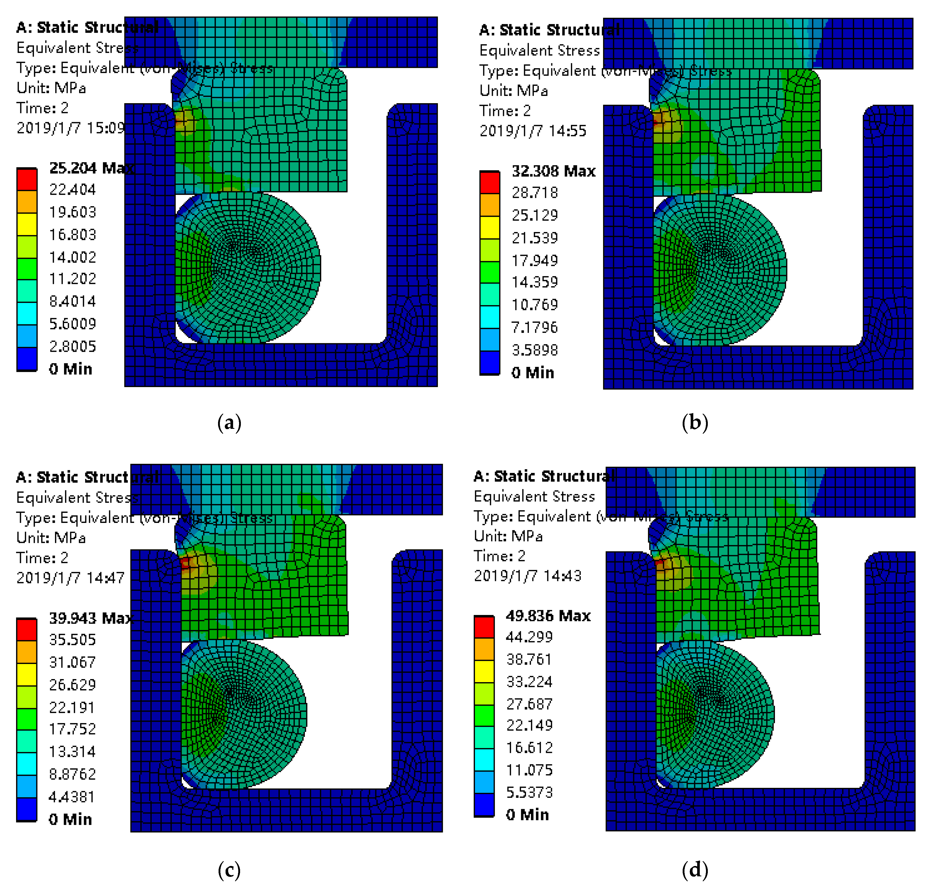
3.2. Effect of O-Ring Pre-Compression (Compression Ratio) on Sealing Performance

The compression ratio of the O-ring directly determines the contact stress of the II and III sealing surfaces. Working pressures of 10 MPa, 15 MPa, 20 MPa, and 25 MPa and compression rates of 15~25% (the size of each increment is 2.5%) were analyzed. The contact stress of the three sealing surfaces I, II, and III and the maximum stress of the combined sealing ring were obtained as shown in Table 2, Table 3, Table 4 and Table 5.
From the table above, it can be seen that when the working pressure reaches 20 MPa, the maximum contact stress at I decreases with the increase in the compression rate. This is because the contact bandwidth between the wear ring and the O-ring increases with the increase in the compression rate, which leads to a decrease in the oil-bearing area and a decrease in the contact stress of the wear ring. The contact stress at II increases with the increase in the compression ratio, so it is feasible to increase the compression ratio if the contact stress is to be increased to match the sealing performance. However, when the working pressure is 25 MPa and the compression rate is 25%, the maximum contact stress at I decreases to less than the working pressure. This shows that the greater the compression rate is, the better the sealing effect is. It is particularly important to select a compression rate that is suitable for the working conditions.
At the same compression rate, the maximum contact stress increases with the increase of pressure. When the compression rate is 15%, the maximum contact stress change range at I is 10.941~26.807 MPa, and the maximum contact stress change range at II is 16.53~29.916 MPa. The maximum contact stress variation range at III is 12.779~20.716 MPa. Under the same structural conditions, the main influence on the maximum contact stress at III is the pre-compression of the O-ring.
When designing the groove for O-ring installation, the influence of working pressure should be fully considered, the most suitable compression rate parameter should be selected according to the range of the working pressure, and the piston groove size should be designed.
Therefore, when designing a groove for O-ring installation, the influence of the working pressure should be fully considered. According to the range of working pressures, the most suitable compression rate parameter should be selected for the design of the piston groove.

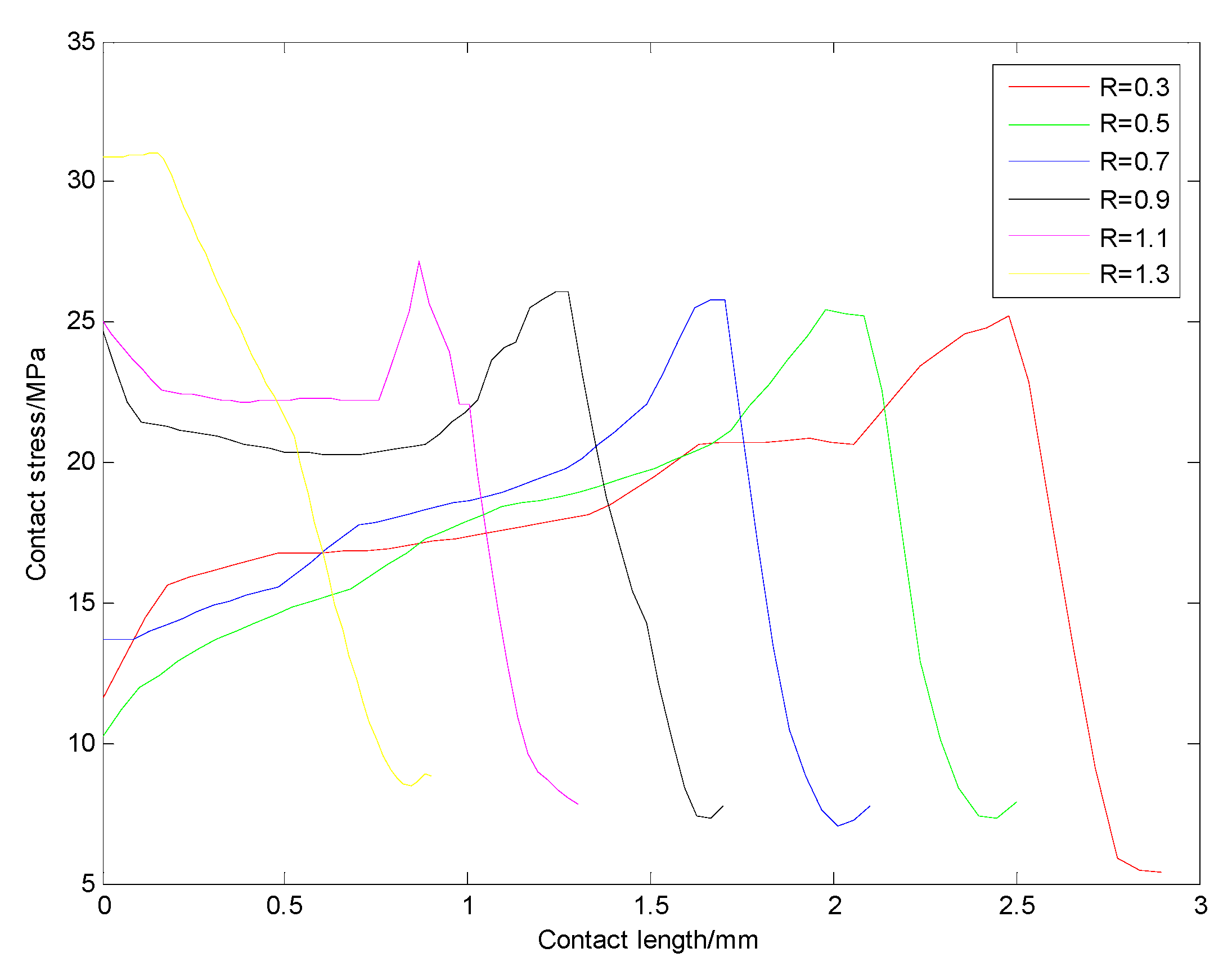
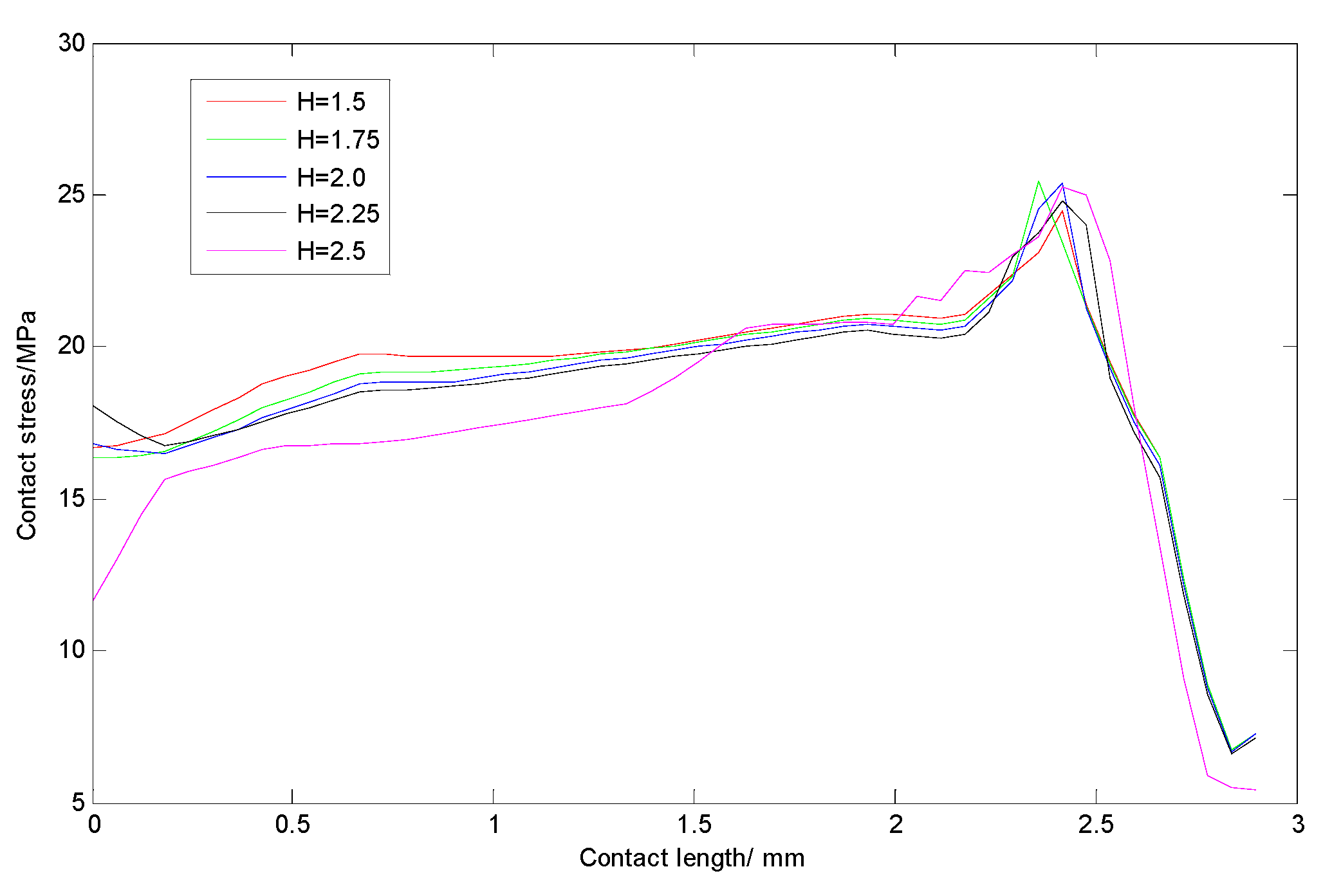
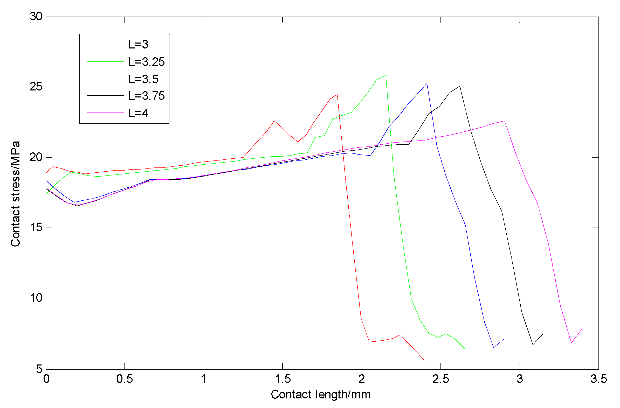
3.3. Effect of Wear Ring Structure Size on Sealing Performance

The shape of the cross-section of a wear ring will affect the distribution of contact stress on the sealing surface and directly affect the magnitude of the friction force. The influence of the chamfer R, thickness H, and width L of the wear ring on the sealing performance was analyzed. The working pressure was 25 MPa and the compression rate was 22.5%.
For the influence of chamfer R, we took the thickness of the wear ring H as 2.5 mm and the width L as 3.5 mm, while the value range of chamfer R was defined as 0.3 mm to 1.3 mm. The size of each increment was 0.2 mm. The contact stress of three sealing surfaces I, II, and III and the maximum Von Mises stress of the combined ring were analyzed.
Figure 6 shows the distribution of contact stress at I under different chamfer R. From the figure, it can be seen that the chamfer R increases continuously, the contact length decreases, and the overall contact stress at I tends to increase.
It can be seen that under the same working pressure, although the maximum contact stress at I increases with the increase in the chamfer R size, compared with R = 0.3 mm and R = 0.5 mm, the contact pressure F decreases by 8.04%.
For the influence of the thickness H of the wear ring, we took the chamfer R as 0.3 mm and width L as 3.5 mm, and defined the thickness H in the range of 1.5 mm to 2.5 mm. The size of each increment was 0.25 mm. The contact stress of I, II, and III sealing surfaces and the maximum Von Mises stress of the combined ring were analyzed.
As can be seen from Figure 7, with the increase in the thickness H, the contact width, maximum contact stress, and position where the maximum stress appeared did not change much.
It can be seen that, under the same working pressure, the thickness of the wear ring H has no obvious influence on the contact stress of the three sealing surfaces I, II, and III. The contact pressure F decreased slowly with the increase in thickness H. Compared with H at 2 mm and H at 2.5 mm, the contact pressure decreased by 3.93%.
For the influence of the wear ring width L, we took R as 0.3 mm and H as 2.5 mm and defined the range of width L as 3.0 mm to 4.0 mm. The size of each increment was 0.25 mm. The contact stress of the three sealing surfaces I stress of the combined ring were analyzed.
As can be seen from Figure 8, with the increase in width L, the maximum contact stress first increased and then decreased, with the peak of the maximum stress shifting toward the charging side.
It can be seen that, under the same working pressure, the contact stress of the three sealing surfaces of I showed no obvious change with the wear ring width L. The value of contact force F increased with the increase in width L. Compared with L = 3.25 mm, the value of contact force F increased by 21.16% when L was 3.75 mm.
Therefore, the chamfer, thickness, and width of the wear ring should be selected to be within a certain range to ensure sealing and reduce friction when the working pressure and compression ratio of the O-ring are constant.

4. Conclusions

In this study, the influence of the working pressure and pre-compression ratio of the rubber O-ring on the contact stress of the combined seal ring was studied, and the influence of the chamfer R, thickness H, and width L of the wear ring on the performance of the composite seal was discussed. The following conclusions can be drawn: (1) The maximum stress on the sealing ring is proportional to the working pressure. (2) In the process of using the combined sealing ring, it is not that the greater the compression ratio of the O-ring is, the better the sealing effect is. It is important to select a compression ratio that is suitable for the working pressure. (3) Under a certain working pressure and compression ratio, friction can be effectively reduced by increasing the chamfer R of the wear ring or decreasing the width L of the wear ring, but at the same time, sufficient contact stress must be guaranteed. (4) When the working pressure and compression ratio are determined, the friction can be effectively reduced by increasing the chamfer R of the wear ring or decreasing the width L.
It is important to note that the simulation analysis carried out in this article considered the sealing and lubrication effects under ideal conditions; thus, only relevant simulation analyses at conventional pressure were carried out. In the future, the influence of high temperatures, high pressures, and wear ring material needs to be studied.

Author Contributions

Software, H.C. and X.C. (Xiaolan Chen); formal analysis, H.C. and H.L.; investigation, H.C.; writing—original draft, H.C.; writing—review and editing, X.C. (Xinyuan Chen); All authors have read and agreed to the published version of the manuscript.

Funding

The authors are thankful for financial support from Wuhan Enterprise Technology Innovation Project, No. 2020020602012133, Key Laboratory Open Fund (Study on the Mechanism of Gap Sealing Hydraulic Cylinder Based on Intelligent Materials No.MECOF2021B05), Central Guidelines Local Science and Technology Development Project of Hubei (Modular Refactoring Intelligent Manufacturing Key Technology and Verification Platform R & D and Application, No. 2020ZYYD018), Guiding project of Hubei Provincial Department of Science and Technology (35KV and below electromagnetic voltage transformer fault detection and analysis, No. B2016211).

Institutional Review Board Statement

Not applicable.

Informed Consent Statement

Not applicable.

Data Availability Statement

The data provided in the article is not public data.

Acknowledgments

Thanks to WUST to support in software simulation. Thanks to Xinyuan Chen to provide analysis and guidance.

Conflicts of Interest

No conflict of interest.

References

  1. Hongbao, L. Research on the key technology of metal ring self-adaptive sealing. Hydraul. Pneum. 2014, 7, 31–33. [Google Scholar]
  2. Heipl, O.; Murrenhoff, H. Friction of hydraulic rod seals at high velocities. Tribol. Int. 2015, 85, 66–73. [Google Scholar] [CrossRef]
  3. Jun, J.; Yuan, G.; Liangcai, Z.; Congchang, Z.; Shuguang, F. Simulation analysis of the leakage of the gap seal hydraulic cylinder. Lubr. Seal. 2013, 38, 75–79. [Google Scholar]
  4. Yu-Ming, P.X.D.W.; Kun, H.X.L. State-of-the-Art and future development of sealing technology. Hydraul. Pneum. Seals 2009, 4, 4–11. [Google Scholar]
  5. Guibin, T. Advances in tribology onelastomer sealing and its future trends for the huge machinery. Tribology 2016, 36, 559–566. [Google Scholar]
  6. Ping, Y.T.; Sheng, Z.Y.; Hiatao, B. Sealingprinciple of new type combined seal and its application. Mach. Tool Hydraul. 2003, 1, 244–245. [Google Scholar]
  7. Bingqing, W.; Xudong, P.; Xiankai, M. Analysis of sealing performance of a hydraulic glyd-ring seal based on soft ehl model. Tribology 2018, 1, 75–83. [Google Scholar]
  8. Ylinen, A.; Marjamaki, H.; Makinen, J. A hydraulic cylinder model for multibody simulations. Comput. Struct. 2014, 138, 62–72. [Google Scholar] [CrossRef]
  9. He, Q.; Huang, W.; Liu, Y.; Liu, X.; Li, Y.; Wang, Y. Contact status between seal ring and its support: Crucial factor in hydrostatic mechanical face seal. Ind. Lubr. Tribol. 2019, 71, 885–892. [Google Scholar] [CrossRef]
  10. Mezghani, S.; Demirci, I.; Zahouani, H. The effect of groove texture pattems on piston-ring pack friction. Precis. Eng. 2012, 36, 210–217. [Google Scholar] [CrossRef] [Green Version]
  11. Johansson, S.; Nilsson, P.; Ohlsson, R. Experimmental friction evaluation of cylinder liner/piston ring contact. Wear 2011, 271, 625–633. [Google Scholar] [CrossRef]
  12. Kapsiz, M.; Durat, M.; Ficici, F. Friction and wear studies between cylinder liner and piston ring pair using Taguchi design method. Adv. Eng. Softw. 2011, 42, 595–603. [Google Scholar] [CrossRef]
  13. Grabon, W.; Koszela, W.; Pawlus, P. Improving teibological behaviour of piston ring-cylinder liner frictional pair by liner surface texturing. Tribol. Int. 2013, 61, 102–108. [Google Scholar] [CrossRef]
  14. Tran, X.B.; Hafizah, N.; Yanada, H. Modeling of dynamic frition behaviors of hydraulic cylinders. Mechatronics 2012, 22, 65–75. [Google Scholar] [CrossRef]
  15. Yang, C.Z.; Guo, Z.; Xu, C. Effect of grooved cylinder liner depths on the tribological performances of cylinder liner-piston ring. Ind. Lubr. Tribol. 2019, 72, 465–471. [Google Scholar] [CrossRef]
  16. Hingawe, N.D.; Bhore, S.P. Tribological performance of a surface textured meso scale air bearing. Ind. Lubr. Tribol. 2019, 72, 599–609. [Google Scholar] [CrossRef]
  17. Quan, S.; Guo, Y.; Liu, X.; Chen, Z.; Liu, Y. Analysis of lubrication and sealing performance on textured piston pair with multi-factor coupling. Ind. Lubr. Tribol. 2021; ahead-of-print. [Google Scholar] [CrossRef]
  18. Shen, C.; Khonsari, M.M. Tribological and Sealing Performance of Laser Pocketed Piston Rings in a Diesel Engine. Tribol. Lett. 2016, 64, 26. [Google Scholar] [CrossRef]
  19. Guo, Z.; Yuan, C.; Liu, P.; Peng, Z.; Yan, X. Study on Influence of Cylinder Liner Surface Texture on Lubrication Performance for Cylinder Liner–Piston Ring Components. Tribol. Lett. 2013, 51, 9–23. [Google Scholar] [CrossRef]
  20. Yan, C.; Jia, X.; Jiang, B.; Gao, L.; Guo, F. Influence of oil temperature on the lip seal’s performance. Tribol. Trans. 2019, 1, 739–746. [Google Scholar] [CrossRef]
  21. Jian, Z.; Qinghui, X.; Hong, J. Parametric modeling and sealing performance analysis of Glyy ring based on Abaqus/CAE. Hydropneumatics Seal. 2017, 37, 35–38. [Google Scholar]
  22. Bingqing, W.; Sancheng, Y.; Xiangkai, M. Sealing performance analysis of high-pressure star-shaped sealing ring. Fluid Mach. 2017, 8, 37–42. [Google Scholar]
  23. Brando, H.C.; Daniel, M.C.; Carlos, P.G.; Marlen, D.S.; Jhon, P.L. Influence of compression rings on the dynamic characteristics and sealing capacity of the combustion chamber in diesel engines. Lubricants 2021, 9, 25. [Google Scholar] [CrossRef]
  24. Foko, F.F.; Heimes, J.; Magyar, B.; Sauer, B. Friction Energy-Based Wear Simulation for Radial Shaft Sealing Ring. Lubricants 2020, 8, 15. [Google Scholar] [CrossRef] [Green Version]
  25. Kurt, M. Testing elastomers for hyperelastic material models in finite element analysis. Rubber Technol. Int. 1999, 88, 36–42. [Google Scholar]
  26. Dolce, M.; Cardone, D.; Croatto, F. Frictional Behavior of Steel-PTFE Interfaces for Seismic Isolation. Bull. Earthq. Eng. 2005, 3, 75–99. [Google Scholar] [CrossRef]
  27. Kong, J.; Liang, Z.; Zhu, T. Structural analysis and improvement measures of rubber track. Constr. Mach. Equip. 2002, 6, 27–30. [Google Scholar]
Figure 1. Combined sealing structure and force section view.
Applsci 12 00714 g001
Figure 2. Combination seal ring contact analysis settings.
Applsci 12 00714 g002
Figure 3. Combined sealing structure grid model.
Applsci 12 00714 g003
Figure 4. Combination seal ring convergence analysis.
Applsci 12 00714 g004
Figure 5. Stress cloud diagram of combined sealing structure. (a) P1 = 10 MPa; (b) P2 = 15 MPa; (c) P3 = 20 MPa; (d) P4 = 25 MPa.
Applsci 12 00714 g005
Figure 6. Distribution of the contact stress along contact path I at different chamfering R (mm).
Applsci 12 00714 g006
Figure 7. Distribution of contact stress along contact path at I at different thicknesses H (mm).
Applsci 12 00714 g007
Figure 8. Distribution of contact stress along the contact path at I at different widths L (mm).
Applsci 12 00714 g008
Table 1. Material table of the hydraulic cylinder and combined sealing ring.
NameMaterialElastic ModulusPoisson’s Ratio
PistonASTM (1.1191/C45E): 1045 (HRC55)210 GPa0.3
CylinderASTM (1.1191/C45E): 1045 (HRC55)210 GPa0.3
Wear ringPTFE (polytetrafluoroethylene)280 MPa0.4
O-ringnitrile-butadiene rubber7.8 MPa0.499
Table 2. Contact stress and compression ratio (working pressure 10 MPa).
Compression Ratio15%17.5%20%22.5%25%
Von-mises stress (MPa)28.99123.56225.37319.36720.633
Contact stress at I (MPa)10.94110.67911.23911.97213.292
Contact stress at II (MPa)16.5317.42618.57519.06719.731
Contact stress at III (MPa)12.77913.70714.56315.41616.251
Table 3. Contact stress and compression ratio (working pressure 15 MPa).
Compression Ratio15%17.5%20%22.5%25%
Von-mises stress (MPa)36.63336.0538.52735.7331.777
Contact stress at I (MPa)15.68815.33115.10715.07915.729
Contact stress at II (MPa)21.12721.93622.24723.84824.533
Contact stress at III (MPa)15.26316.39917.28118.13519.022
Table 4. Contact stress and compression ratio (working pressure 20 MPa).
Compression Ratio15%17.5%20%22.5%25%
Von-mises stress (Mpa)43.28847.97847.06636.26242.782
Contact stress at I (Mpa)21.50120.92920.61220.57420.004
Contact stress at II (Mpa)25.75226.68526.92927.54328.008
Contact stress at III (Mpa)17.97419.520.18420.7721.716
Table 5. Contact stress and compression ratio (working pressure 25 MPa).
Compression Ratio15%17.5%20%22.5%25%
Von-mises stress (Mpa)49.58860.60553.03645.41853.243
Contact stress at I (Mpa)26.80725.92425.97725.22624.979
Contact stress at II (Mpa)29.91631.08231.5432.2732.97
Contact stress at III (Mpa)20.71622.17424.84125.23626.339
Publisher’s Note: MDPI stays neutral with regard to jurisdictional claims in published maps and institutional affiliations.

