Article

Effect of Buildings on the Radiation Characteristics of MF Broadcast Antennas

by
George S. Liodakis
,
Melina P. Ioannidou
,
Nikolaos S. Petrakis
,
Anargyros T. Baklezos
,
Theodoros N. Kapetanakis
,
Christos D. Nikolopoulos
and
Ioannis O. Vardiambasis
*
Laboratory of Telecommunications and Electromagnetic Applications, Department of Electronic Engineering, Hellenic Mediterranean University, 73133 Chania, Crete, Greece
*
Author to whom correspondence should be addressed.
Appl. Sci. 2022, 12(13), 6525; https://doi.org/10.3390/app12136525
Submission received: 4 May 2022 / Revised: 12 June 2022 / Accepted: 25 June 2022 / Published: 27 June 2022
(This article belongs to the Collection Electromagnetic Antennas for HF, VHF, and UHF Band Applications)

Abstract

:
This study aims to investigate the impact of the presence of buildings on the radiation characteristics of MF broadcast antennas. Two different antennas are considered: a monopole operating at 1494 kHz and a two-element linear array radiating at 1008 kHz. The buildings were modeled as wire-grids and the total electric field intensity was calculated as the sum of the scattered field by the wire-grid and the field radiated from the antenna in free space. The radiation pattern of the antennas, when one or two buildings were situated in their vicinity, were the end result of the analysis, and they were compared to the corresponding patterns in free space. The results demonstrate that the radiation characteristics of antennas are mostly affected by the heights of buildings. If these heights are less than a critical value, the buildings do not significantly obstruct the operation of the antenna, despite the value of other parameters, such as the length and the width of the buildings, as well as their distance from the antenna.

1. Introduction

Although the problem of the propagation of MF (medium-frequency) and HF (high-frequency) waves in built-up areas has long been considered [1], there is a very limited number of available studies focusing on the effects one should expect on the radiation characteristics of MF and HF broadcast antennas due to blockage [2]. Most papers that deal with antenna blockage focus on frequencies higher than 1 GHz [3,4,5,6].
Studies that deal with the propagation of MF and HF waves in the presence of obstacles, such as buildings, concentrate mostly on the prediction and measurements of the propagation losses [1,7,8,9,10,11]. The propagation along a rounded hill assumed to have a knife-edge obstruction was analyzed by Wait [7]. MF and HF ground-wave propagation in urban areas were examined by introducing a new method for the modeling of buildings [8]. Propagation in HF, VHF, and UHF bands, in a wide range of environments, was the subject of [9], including the study of the effect that building blockage has on degrading the propagation distance at each frequency band. The signal attenuation caused by the terrain obstruction of path profiles in the MF band was investigated in [10] by modeling the terrain irregularities as triangular-wedge-shaped obstacles. The impact of buildings on the far field of a broadcasting antenna was examined in [11] by using a finite-difference method. Furthermore, the effect of buildings on the radiation characteristics of an antenna or an antenna array was studied in [12,13].
The impact of local terrain topology on the radiated electric near field of HF broadcast antennas was examined by [14], in an attempt to assess human exposure to electromagnetic radiation in close proximity to high-power HF transmitters. The changes in the antenna response associated with the geometry of the buildings and the effect of the latter on the HF direction was analyzed by using the method of moments (MoM) and the physical optics (PO) technique [15]. Recently, blockage effects on HF antennas were studied; their influence on the radiation characteristics was analyzed and a relationship between the antenna and the size of the blockage was determined [2]. Furthermore, the modeling and simulation of the influence of buildings on the signals of navigation devices for aviation were presented in [16,17,18]. Recently, the wireless performance of buildings has been extensively studied [19,20,21,22,23]; interference-signal blockage is examined in [19], the interference gain and the power gain are adopted to assess the impact of buildings on the power of signals in [20,21], the building wireless performance (BWP) when the building materials are integrated with antenna arrays is evaluated in [22], while an overview of the BWP is offered in [23]. Moreover, the performance of concrete-embedded antennas is investigated in [24] by using artificial neural networks.
In this study, we present an investigation of the antenna blockage by buildings in MF broadcasting; our literature survey revealed that similar studies are particularly lacking and there is a lack of models that address pertinent problems. The aim of this study is to estimate the distance from a broadcast antenna at which buildings have negligible effects on its radiation characteristics by taking into account the size/height of these buildings. Since broadcast antennas may be found near residential areas, it is essential to determine how far from the antenna we may construct buildings and the maximum number of stories that permit the unimpeded operation of the antenna. The main contribution of our work is a solution to the aforementioned “real-life” problem by combining existing methods and techniques. The buildings are modeled as wire-grid bodies, considering their steel frame construction; the presence of these bodies in the vicinity of a radiating antenna is taken into account in order to determine the change in the antenna’s free-space radiation pattern. Evidently, buildings are far more complex bodies and contain a variety of components with different electrical and mechanical characteristics. However, the accurate modeling of buildings is beyond the scope of this paper. The wire-grid model used herein implies a perfectly conductive body; thus, it may be considered as the worst-case scenario regarding the effect of buildings on the radiation characteristics of the antenna.
A description of the models used herein for the antenna and the buildings is given in Section 2. Two types of MF antenna are considered, and the buildings are assumed to consist of wire segments that form a rectangular parallelepiped mesh. Both components of the electric field intensity, i.e., the field radiated by the antenna and the scattered field by the building-model, are taken into account. The indicative results concerning the antenna radiation pattern in the presence of buildings, are provided in Section 3, while the discussion in Section 4 focuses on establishing a quantitative relationship between the size of the building and its effect on the antenna radiation. Finally, Section 5 comprises the conclusions of our study.

2. Materials and Methods

2.1. Antenna and Ground Modeling

Two types of antenna were considered: (a) a vertical, linear antenna named, hereafter, monopole, and (b) a two-element array consisting of two vertical monopoles, simply termed array.
The monopole was assumed to operate at 1494 kHz; its length was h = 84 m, i.e., h = 0.418 λ , with λ standing for the wavelength. The antenna was fed at its end point and the transmitted power was assumed to be P = 50 kW. Since the diameter of the (cylindrical) wire was D = 1.94 m, D / h = 0.023 and D / λ = 0.0097 . Thus, the monopole may be considered to have a negligible diameter [25].
The two monopoles that constitute the array were assumed to operate at 1008 kHz; their length was 149 m ( h = 0.501 λ ) and their distance was d = 75 m. They were fed at their end point and the transmitted power by each element was P 1 = 33 kW and P 2 = 17 kW, respectively. The diameter of each (cylindrical) element was assumed to be D = 1.94 m. Therefore, the monopoles may be considered of negligible diameter, since D / h = 0.013 and D / λ = 0.0065 .
The antennas were assumed to be mounted on the ground, which, generally, is not a perfect electric conductor (PEC) since its usual conductivity does not exceed 10 1 mho/m. However, since the radiation characteristics of an antenna depend on the ground conductivity, it is convenient to “create” an artificial PEC ground. The latter may be formed by mounting the antenna above a metal surface much greater than the antenna dimensions, which is prohibitive for MF antennas. Alternatively, the PEC surface may be replaced by metal strips or wires arranged on the ground, radially, around the antenna. As regards the monopole, 180 metal wires, 50 m long with a 2-mm diameter, were placed radially (every 2 deg) on the ground. A similar artificial PEC ground was assumed for the array; 120 metal wires, 75 m long, were arranged radially (every 3 deg) on the ground, around the antenna.
It is well known that a monopole of length h sitting on a PEC ground plane is equivalent to a center-fed, linear dipole of length 2h, in free space [26]. Thus, the monopole on the PEC ground plane, as described above, may be modeled as a dipole of length 2 h = 0.836 λ (Figure 1a), whereas the monopoles that constitute the aforementioned two-element array are equivalent to dipoles of length 2 h = 1.002 λ (Figure 1b) in free space.

2.2. Current Distribution

For a very thin dipole, such as the model described in the previous section, a good approximation for the current distribution is [25]
I ( x , y ,   z ) = { z ^ I m s i n [ k ( h z ) ] ,     0 z h   z ^ I m s i n [ k ( h + z ) ] ,     h z 0  
where k = 2 π / λ stands for the wavenumber and I m sin ( k h ) = 2 P / R e { Z i n } is the current at the feed point (for negligible losses); Z i n represents the input impedance of the antenna.
As regards the dipole in Figure 1a, we assume that P = 50 kW and Z i n = 300 j 217.5 , thus, the amplitude is readily calculated: I m = 37.306 A. For the dipole array in Figure 1b, I m 1 = 26.87 A and I m 2 = j   11.31 A, where I m 1 refers to the antenna that emits 33 kW and I m 2 to the dipole that emits 17 kW.

2.3. Building Modeling

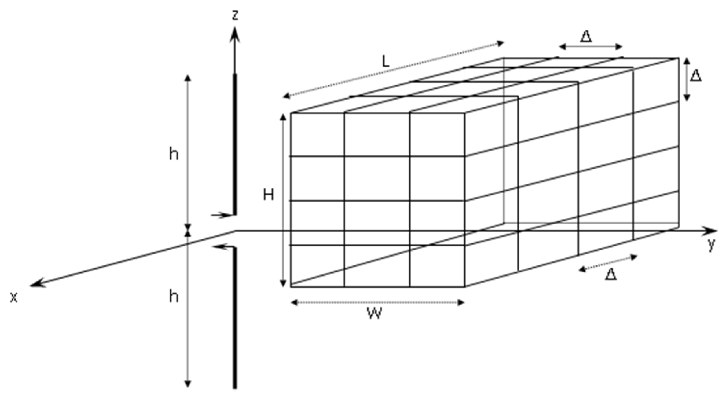
A building may be modeled as a rectangular parallelepiped with façade length L, width W, and height H. It is assumed to comprise from 2 up to 16 stories, each story being at least 50   m 2 and about 5 m high; thus L, W, and H may span the range 10 L 50 m, 10 W 50 m, and 10 H 80 m, respectively. An issue that arises when modeling a building is its orientation. As shown in Figure 2, the antenna is placed along z-axis, whereas the length L is assumed to be parallel to the x-axis, i.e., the façade of the building faces the antenna; W is taken parallel to the y-axis and H is parallel to the z-axis.
The materials of buildings are, obviously, not uniform and difficult to model. They comprise several conductive (steel frame, copper cables, metal pipes, etc.) and dielectric (bricks, glass, concrete, marble, etc.) parts that may or may not exhibit a certain conductivity. Herein, the buildings are modeled as wire-grid bodies [27], for the sake of simplicity. It should be noted that, since the wires were taken as PEC, the aforementioned model constitutes the worst-case scenario in terms of the effect on the radiation characteristics of the antenna. The grid consists of similar wires at a distance Δ ; the radius of each wire is a = Δ / 10 [28]. Thus, the whole building comprises ( L / Δ + 1 ) × ( W / Δ + 1 ) × ( H / Δ + 1 ) wire segments arranged in a mesh, as shown in Figure 2.

2.4. Scattering from a Wire Grid

A point-matching solution to the problem of scattering by a wire-grid model has already been developed by Richmond [27]. A brief outline of this solution is given below.
The elementary scatterer is a short, thin wire segment of length Δ . By assuming that Δ λ , the current density may be taken as uniform over the surface of each segment. The electric field intensity of this source, i.e., the scattered field of each segment, may be expressed as a surface integral over the surface of the wire. Subsequently, we enforce the boundary conditions: the tangential electric field intensity should vanish everywhere on the surface of each PEC segment. However, if the wire is thin, it is sufficient to zero the tangential electric field at just one point at the center of each segment. The end result of the analysis described above is a set of N linear equations, where N is the total number of segments:
j = 1 N S i j I j = E i i n c ,         i = 1 , 2 , , N
In Equation (2), S i j represents the scattering coefficient, i.e., the tangential component of the electric field intensity radiated by segment j (with unit current) when the observation point is at the center of segment i, I j stands for the (unknown) current induced on segment j, and E i i n c is the tangential component of the incident electric field intensity at the center of segment i. The scattering coefficients S i j are calculated in the Appendix of [27]; the explicit expression for S i j is given by Equation (24) in [27] and is omitted for the sake of brevity.
The system (2) may be solved numerically in order to obtain the unknown currents, provided that E i i n c is known. Herein, the latter is actually the field intensity radiated by an antenna, and it is discussed in Section 2.5. Subsequently, the vector potential A i is calculated from:
A i = A i i ^ = μ s i I i 4 π r exp [ j k r + j k ( x i sin θ cos φ + y i sin θ sin φ + z i cos θ ) ] i ^
The unit vector i ^ in Equation (3) denotes the direction parallel to segment i, s i is the length of segment i, which is equal to Δ for the case examined herein, and ( x i , y i , z i ) are the Cartesian coordinates of the center of segment i. Finally, the distant scattered field is found as follows:
E θ s c a = j ω i = 1 N [ cos θ cos a i ( cos φ cos b i + sin φ sin b i ) + sin θ sin a i ] A i
E φ s c a = j ω i = 1 N ( sin φ cos b i cos φ sin b i ) A i cos a i
The angles a i and b i , in Equation (4), denote the orientation of segment i according to: i ^ = x ^ cos a i cos b i + y ^ cos a i sin b i z ^ sin a i .

2.5. Radiation of the Antennas in the Presence of Buildings

Let us consider an antenna that radiates in free space. It is well known [13] that the space surrounding the antenna is subdivided into three regions: (a) the reactive near-field, where 0 < r < 0.62 ( 2 h ) 3 / λ ; (b) the radiating near-field, where 0.62 ( 2 h ) 3 / λ r < 2 ( 2 h ) 2 / λ ; and (c) the far-field, where r 2 ( 2 h ) 2 / λ . In terms of the monopole that radiates at 1494 kHz, 2 h = 0.836 λ with λ = 200.803 m. Thus, the boundaries for the reactive and radiating near-field are 0 < r < 95.16 m and 95.16 r < 280.68 m, respectively, while the far-field is at a distance r 280.68 m. For the array operating at 1008 kHz, 2 h λ = 297.619 m and the boundaries for the reactive and radiating near-field are 0 < r < 184.88 m and 184.88 r < 596.76 m, respectively. For r 596.76 m, the space may be considered as far-field.
Explicit expressions for the electric field intensity at the aforementioned distinct regions, for both antennas, may be found in [25] and are given below.
The non-zero components of the far field of the monopole are:
E θ , m o n j ζ I m e j k r 2 π r [ cos ( k h cos θ ) cos ( k h ) sin θ ] ,       H φ , m o n = E θ , m o n ζ
where ζ = 120 π   ( Ω ) stands for the free-space impedance. The non-zero components of the radiating near-field of the monopole are given by:
E ρ , m o n = j ζ I m 2 π ρ [ ( z h ) e j k R 1 R 1 + ( z + h ) e j k R 2 R 2 2 z cos ( k h ) e j k r r ]
E z , m o n = j ζ I m 4 π [ e j k R 1 R 1 + e j k R 2 R 2 2 cos ( k h ) e j k r r ]
H φ , m o n = j I m 4 π ρ [ e j k R 1 + e j k R 2 2 cos ( k h ) e j k r ]
with ρ 2 = x 2 + y 2 ; R 1 = ρ 2 + ( z h ) 2 , R 2 = ρ 2 + ( z + h ) 2 , and r = ρ 2 + z 2 are depicted in Figure 1a.
For the array, the corresponding non-zero components of the far field are:
E θ , a r = E θ , m o n S ( θ , φ ) ,       H φ , a r = E θ , a r ζ
whereas the non-zero components of the radiating near-field are written as follows:
E ρ , a r = E ρ , m o n S ( θ , φ ) ,     E z , a r = E z , m o n S ( θ , φ ) ,     H φ , a r = H φ , m o n S ( θ , φ )
S ( θ , φ ) in Equation (8) stands for the array factor and is given by:
S ( θ , φ ) = 1 j I m 1 I m 2 e j k d sin θ cos φ
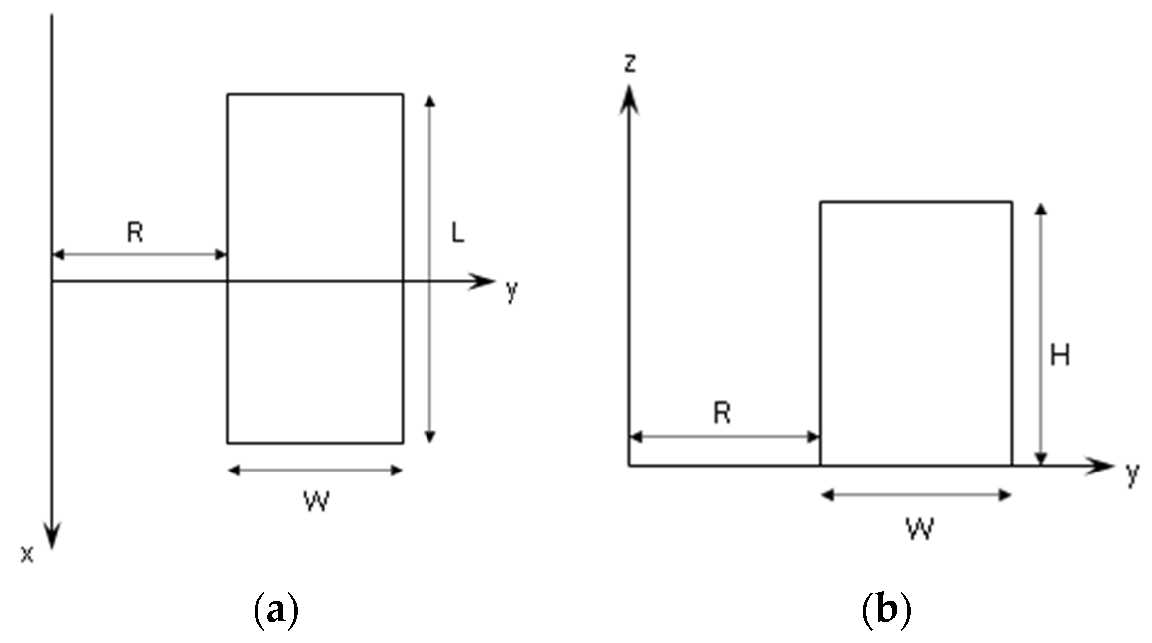
The appropriate Equations (5)–(8), should substitute E i i n c   in Equation (2) in order to formulate the linear set of equations for the unknown currents I j . Obviously, it is the distance R between the antenna and the building that determines the appropriate equations, depending on the region of space. R is defined as the length of the perpendicular bisector from the antenna to the façade of the building, and it is shown in Figure 3. All results presented in Section 3 were produced by assuming that the buildings are in the radiating near-field region of the antenna. Thus, the unknown currents I j for the monopole are calculated from the linear set of equations obtained by substituting E i i n c   in Equation (2) by Equation (6), whereas, for the array, E i i n c in Equation (2) is substituted by the electric-field intensity given by Equation (8).
The set of linear equations resulting from Equation (2) is solved numerically by truncation and matrix inversion after checking the convergence of the solution. For this purpose, a custom computer code was developed in Fortran 90. The wire-grid method used herein, together with the associated computer code, may be considered as a semi-analytical solution to the problem, since it involves the numerical handling of the final set of equations. Thus, it possesses the pros and cons of any such solution. On one hand, it is time- and memory-efficient, whereas its complexity is only related to certain analytical manipulations (carried out once). On the other hand, it may not simulate the shape or material of the buildings in detail. However, since the accurate modeling of the latter is not our main purpose (as explained in the Introduction) the method provides an acceptably accurate solution to the “real-life” problem. It should be noted that this method was chosen in conjunction with the frequency band considered herein and, evidently, it may not be suitable for higher frequencies.

3. Results

The results presented herein focus on the radiation patterns of the monopole and the array in the presence of buildings; all the diagrams include the radiation pattern of the corresponding antenna in free space, for the sake of comparison. It was found that the radiation pattern, among other antenna characteristics, such as the gain and the voltage standing wave ratio (VSWR), were particularly influenced by antenna blockages, not only at the HF band [2], but also at much higher frequencies [3,4,5].
The radiation patterns plotted herein are actually a graphical representation of the magnitude of the far electric-field intensity of the antenna in polar coordinates. The magnitude of the far electric-field intensity in the presence of buildings resulted from the sum of the far-field in free space (i.e., Equation (5) for the monopole or (7) for the array) and the scattered field given by Equation (4). It should be noted that the corresponding radiation patterns in free space were plotted by using (only) Equation (5) or Equation (7) for the monopole and the array, respectively.

3.1. Radiation Patterns of the Monopole

Indicative radiation patterns of the monopole in the presence of one or two buildings are plotted, herein, for different values of the parameters L, W, H, and R. The distance Δ between two adjacent wire segments was taken to be equal to 2.5   m 0.0125 λ .
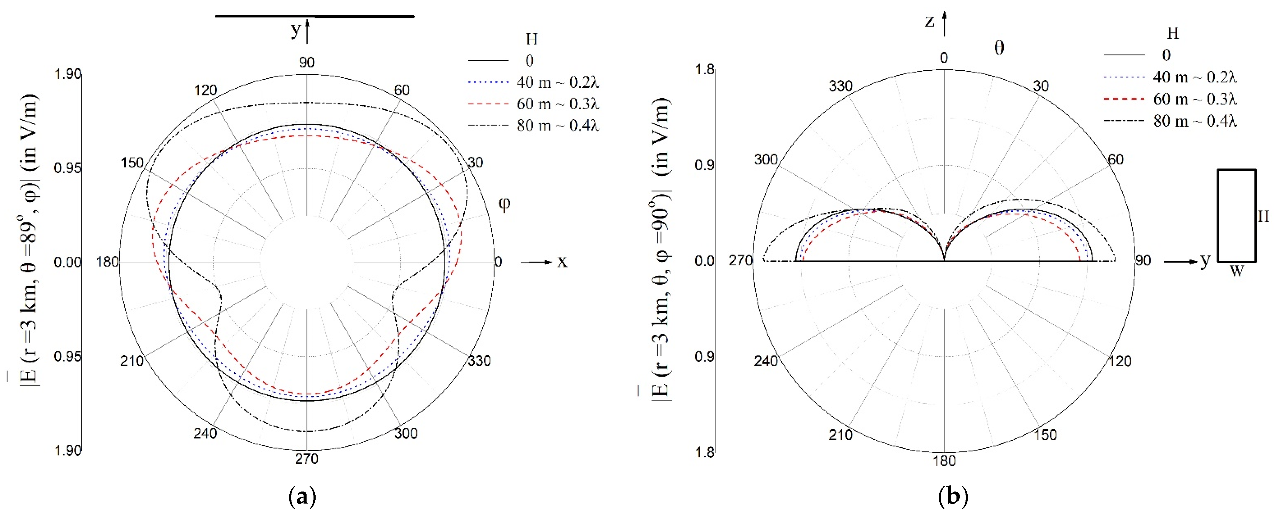
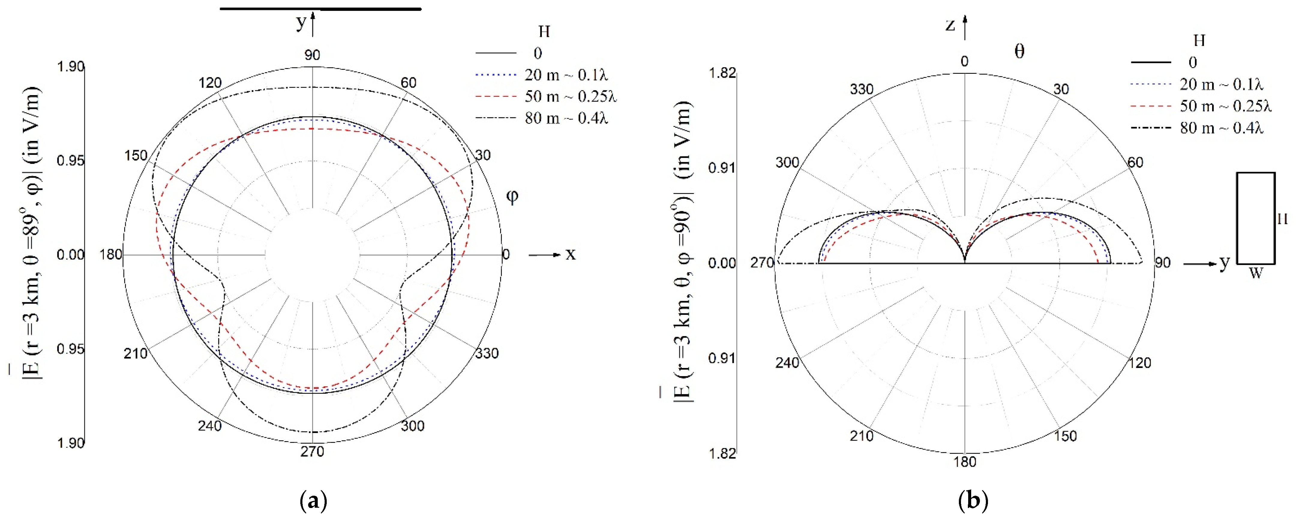
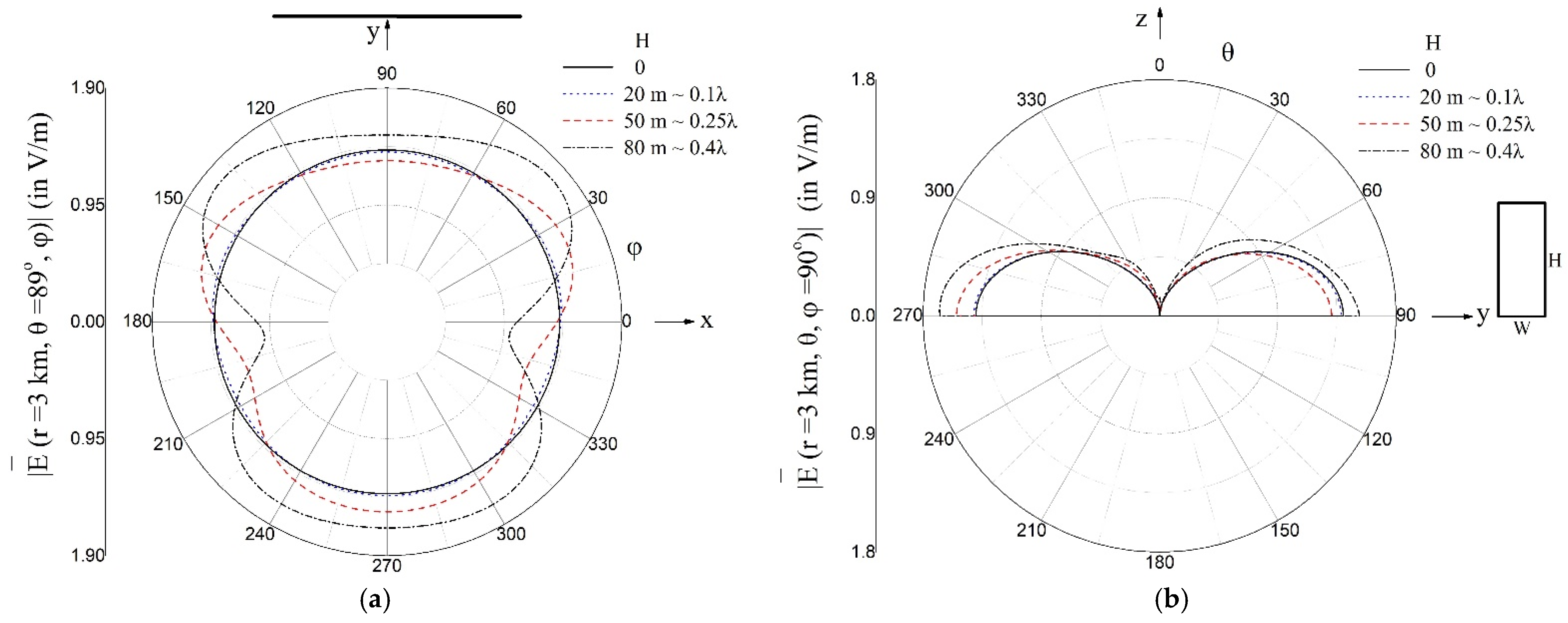
The patterns in Figure 4a and Figure 5a refer to the φ -plane (at a specific value of θ , i.e., θ = 89 o ), while Figure 4b and Figure 5b depict the θ -plane for φ = 90 o . The length L and the width W of the building (given in the inset) were kept constant in order to investigate the effect of the height H on the radiation pattern of the antenna; three different values of H were considered (given in the inset). Moreover, the impact of the distance between the antenna and the building on the radiation pattern was examined by considering two values of R, i.e., R = 100 m (Figure 4) and R = 200 m (Figure 5). Both values indicate that the building was in the radiating near-field region of the antenna.
The influence of the building size on the radiation characteristics of the antenna was investigated through Figure 6 and Figure 7. Figure 6 refers to a building 60 × 10 × H   m 3 , i.e., it has the same width as the building considered in Figure 4, albeit it is six times longer. In Figure 7, the building is 10 × 20 × H   m 3 , i.e., its length is kept the same as the building in Figure 4, albeit its width is six times greater.
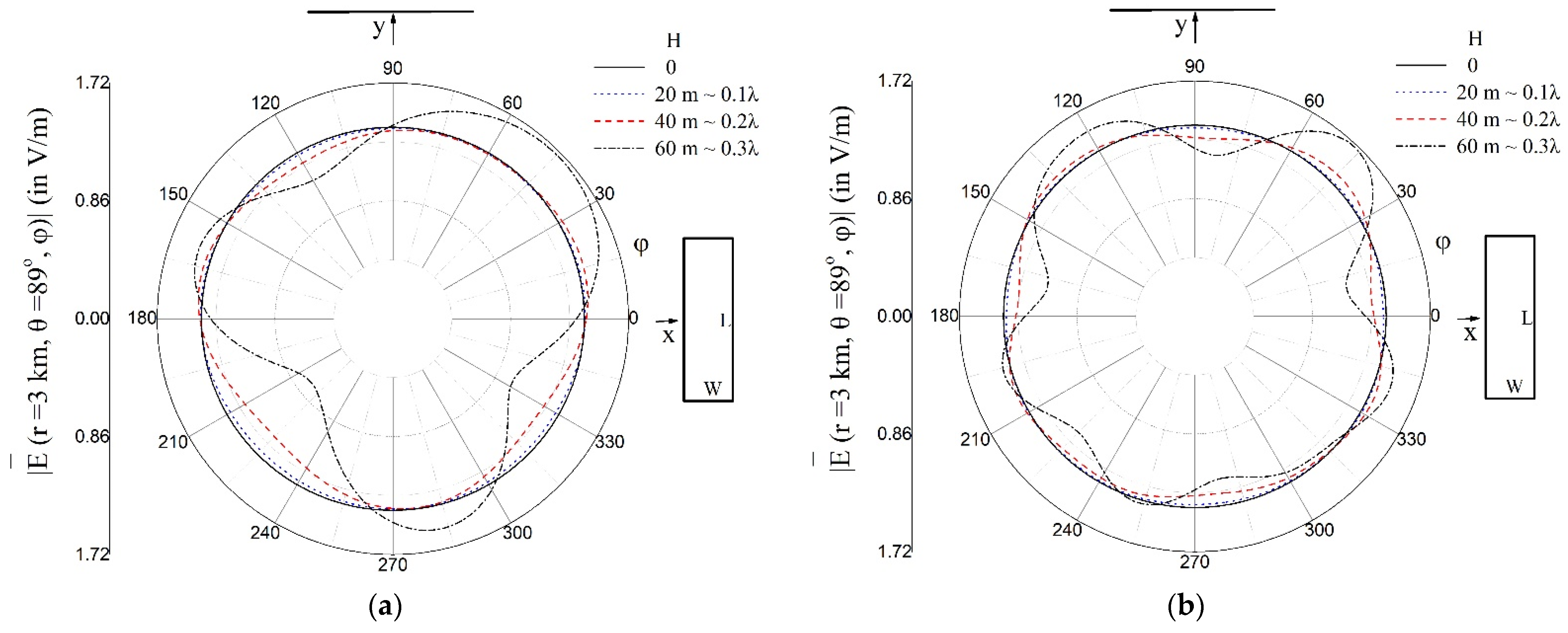
Subsequently, two identical buildings were considered in the vicinity of the radiating antenna. The first was placed along the x-axis, whereas the second was along the y-axis. Each building was assumed to be 100 m (Figure 8a) or 200 m (Figure 8b) from the antenna. The patterns refer to the θ -plane for φ = 90 o , while the φ -plane was omitted for the sake of brevity. The effect of the height H on the radiation pattern of the antenna was investigated by considering three different values of H (given in the inset).

3.2. Radiation Patterns of the Array

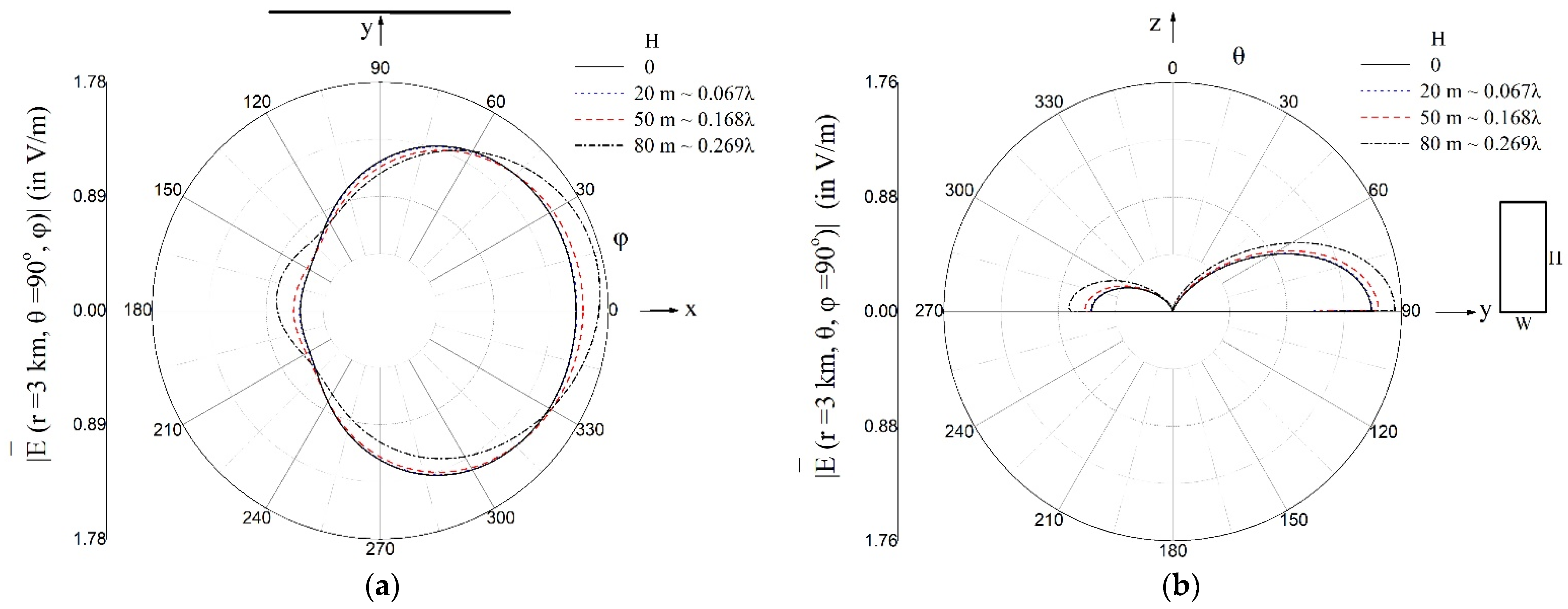
The indicative radiation patterns of the array radiating at 1008 kHz in the presence of one or two buildings (including the corresponding curves in free space) are plotted herein. The patterns in Figure 9a,b refer to the φ -plane (at a specific value of θ , i.e., θ = 90 o ) and the θ -plane (for φ = 90 o ), respectively. The length L and the width W of the building were constant (given in the inset), whereas three different values of H were considered. The distance between the antenna and the building ( R = 100   m 0.34 λ ) indicates that the latter was in the reactive near-field region of the antenna.

4. Discussion

By examining the patterns in Figure 4 and Figure 5, one may conclude that the height of a building situated in the vicinity of a radiating monopole may affect the radiation pattern of the antenna significantly for H 0.3 λ , i.e., H 60 m for f = 1494 kHz, a height that corresponds to a building with 12 stories, provided that each story is 5 m high. It may be readily verified that the blue dotted curve ( H 0.2 λ ) almost coincides with the black solid curve (the pattern in the absence of the building), whereas the patterns in the presence of a building with H 0.3 λ or H 0.4 λ deviate considerably from the omnidirectional pattern. The same remark holds for both distances ( R 0.5 λ = 100 m and R λ = 200 m) between the building and the antenna. Moreover, a comparison between Figure 4a and Figure 5a may lead to the conclusion that the distance between the antenna and the building may affect the radiation pattern only when the height exceeds the critical value of 0.3 λ .
The impact of the length and width of the buildings on the antenna’s radiation pattern was examined by comparing Figure 6 and Figure 7, respectively, with Figure 4. The parameters used to produce Figure 6 were the same as those in Figure 4, except for the length of the building ( L 0.05 λ = 10 m in Figure 4, L 0.3 λ = 60 m in Figure 6), whereas the parameters that appear in Figure 7 are the same as those in Figure 4, albeit the width of the building is six times greater ( W 0.05 λ = 10 m in Figure 4, whereas W 0.3 λ = 60 m in Figure 7). Figure 6 and Figure 7 indicate that the length and the width of the building do not seem to have a significant impact on the radiation pattern of the antenna, as long as the height of the building is kept below a critical value; the blue dotted curves in Figure 4, Figure 6, and Figure 7 (all of which correspond to H = 20   m 0.1 λ , whereas L and W differ according to the captions) are all the same, and they practically coincide with the omnidirectional shape. As the height increases (red dashed curve of Figure 4, Figure 6 and Figure 7, i.e., H = 50   m 0.25 λ ), the pattern deviates slightly from the omnidirectional pattern; however, L (W) has a negligible effect on the pattern, as may be readily verified by comparing the red dashed curve in Figure 6 or Figure 7 with the curve in Figure 4. However, for H 0.3 λ , the radiation of the antenna deviates considerably from the omnidirectional behavior, as indicated by the blue dashed–dotted curves in Figure 4, Figure 6, and Figure 7. In this case, the effects of the length and the width of the building are more pronounced. For the width in particular, a comparison between the blue dashed–dotted curves in Figure 4a and Figure 7a shows that the two patterns differ slightly from each other, apart from the deviation of the omnidirectional shape. It should be noted that several patterns were produced by varying the parameters of the configuration in order to ensure that the above remark held in a vast number of cases. All the results support the aforementioned conclusion and they are omitted for the sake of brevity.
The effect of the presence of two (identical) buildings on the radiation pattern of the monopole is examined in Figure 8. Even a casual glance at the plots in Figure 8 suggests that they follow roughly the same trend as those obtained in the presence of a single building, i.e., the height is the most important parameter that determines whether the other parameters (such as the distance between the antenna and the buildings or the relative position of the buildings) affect the radiation pattern significantly. Indeed, when the two buildings are 20   m high, the pattern for R = 100   m 0.5 λ (blue dotted curve in Figure 8a) almost coincides with the black circle denoting omnidirectional behavior. In Figure 8b, the distance between the antenna and each building is doubled (i.e., R = 200   m λ ) . The latter implies that the distance between the two buildings also changed. However, the blue dotted curve in Figure 8b suggests that the pattern is still almost omnidirectional. As the heights of the buildings increase, the patterns tend to differ significantly from the omnidirectional shape, and the impact of R on the radiation of the antenna becomes more significant. For example, the blue dashed–dotted curves I Figure 8a,b, which correspond to relatively high buildings (i.e., H = 60   m 0.3 λ ), deviate considerably from the circular shape. In this case, the distances between the two buildings and their relative positions become important because the shape of the radiation pattern is altered. This may be readily verified by comparing the shape of the two blue dashed–dotted curves in Figure 8a,b. Moreover, a comparison between Figure 8a,b, Figure 4a and Figure 5a, respectively, indicates that the deviation of the omnidirectional shape occurs at slightly smaller values of H when there are two buildings near the antenna (i.e., H 0.2 λ ) than in the presence of a single building ( H 0.3 λ ).
The remarks reported above for the monopole also hold, more or less, for the two-element array The radiation patterns presented in Figure 9 suggest that a building 50 × 10 × H   m 3 , at a distance 100 m from the antenna, may affect its radiation pattern only for H 0.2 λ . The other results (including radiation patterns in the presence of two buildings), not shown herein for the sake of brevity, indicate that the radiation characteristics of the array may depend on the parameters L, W, and R only if the height of the building exceeds the aforementioned critical value (i.e., 0.2 λ ). The latter was found to be slightly greater for the monopole (i.e., 0.3 λ ), but the trend was roughly the same.
Table 1 offers a comparison of the study presented herein and pertinent works found in the literature. The first three lines in Table 1 comprise three studies [2,11,12], respectively, which, together with the current study, deal with the impact of buildings either on the radiation characteristics of antennas or, more generally, on the far field at MF or HF frequencies. However, ref. [15] deals with the HF band, albeit it focuses on the influence of buildings on direction finding. The familiar result of the present study, i.e., that the height of the buildings is the most important parameter in the distortion of the radiation pattern, was also obtained by other researchers [2,12]. In addition, the conclusion that the impact on the antenna pattern is greater if the size or height of the blockage is larger than λ/2 [2] is not very far from the finding of our study that the effect on the radiation pattern is significant if the height of the buildings is greater than 0.3 λ . The rest of the studies cited in Table 1 [4,6,13,29] refer to higher-frequency bands. Thus, a direct comparison between these works and the present study is not possible; the works are included for the sake of completeness. Moreover, it is interesting to note that, even at such high frequencies, the presence of buildings may distort the radiation patterns and produce side lobes [4,6,13].
For the modeling of buildings, it is common practice to assume that they are conductive bodies (as in the present study) not only at the MF/HF bands [2,11,12], but even at higher frequencies [4,13,29]. The preferred shapes are either cylindrical [4,12,13] or rectangular [2,13,29]; the latter is also assumed herein. The wire-grid method, adopted in our study to model the buildings, has also been used by other researchers [29], albeit in conjunction with the MoM. Recently, Zhu et al. [2] adopted a mesh of metallic wire segments for the simulation of buildings combined with a completely numerical method based on a commercially available software package (FEKO).

5. Conclusions

The influence of the presence of buildings on the radiation pattern of a monopole and a two-element linear antenna array, operating at the MF band, was examined in this paper, in an attempt to assess the distance from a broadcast antenna at which we may construct buildings without obstructing its operation. The buildings were modeled as wire-grid bodies; this assumption constitutes the worst case in terms of their impact on the radiation characteristics of the antenna, although it may not ensure accurate modeling. Our results indicate that the height of the buildings is the most important parameter that may alter the free-space radiation characteristics of antennas. The length and the width of buildings, as well as their distance from the antenna, may only have an impact on the radiation pattern if the height exceeds a critical value; the latter was found to be roughly equal to 0.2 λ when the radiation of the monopole was obstructed by two buildings, as well as when one or two buildings were situated in the vicinity of the two-element array, whereas it was slightly greater (about 0.3 λ ) when the monopole radiated with one building nearby. Thus, the worst-case scenario suggests that buildings may be constructed as close as 0.5 λ from a radiating broadcast MF antenna without obstructing its operation, provided that they have less than eight stories (each about 5 m high). Our future work may include the examination of other shapes (such as cylinders) and materials for building modeling, in conjunction with different methods for the calculation of EM fields around radiating antennas.

Author Contributions

Conceptualization, G.S.L. and I.O.V.; methodology, G.S.L. and I.O.V.; software, G.S.L., N.S.P. and I.O.V.; validation, G.S.L., M.P.I., N.S.P., A.T.B., T.N.K., C.D.N. and I.O.V.; formal analysis, G.S.L., M.P.I., N.S.P. and I.O.V.; investigation, G.S.L., M.P.I., N.S.P., T.N.K., A.T.B., C.D.N. and I.O.V.; resources, G.S.L., N.S.P., C.D.N. and I.O.V.; data curation, G.S.L., N.S.P., T.N.K., A.T.B., C.D.N. and I.O.V.; writing—original draft preparation, G.S.L., M.P.I. and I.O.V.; writing—review and editing, G.S.L., M.P.I. and I.O.V.; visualization, G.S.L., M.P.I., N.S.P., A.T.B., T.N.K., C.D.N. and I.O.V.; supervision, I.O.V.; project administration, I.O.V.; funding acquisition, G.S.L., N.S.P., C.D.N. and I.O.V. All authors have read and agreed to the published version of the manuscript.

Funding

This research received no external funding.

Data Availability Statement

The data used in this study are available on request from the corresponding author.

Acknowledgments

This research is financed by the project “Strengthening and optimizing the operation of MODY services and academic and research units of the Hellenic Mediterranean University”, funded by the Public Investment Program of the Greek Ministry of Education and Religious Affairs.

Conflicts of Interest

The authors declare no conflict of interest.

References

  1. Causebrook, J.H. Medium-wave propagation in built-up areas. Proc. IEE 1978, 125, 804–808. [Google Scholar] [CrossRef]
  2. Zhu, W.; Guo, L.; He, S. Research on HF antenna blockage effects and their alleviation. J. Electromagn. Waves Appl. 2022, 36, 1544–1558. [Google Scholar] [CrossRef]
  3. Dagdeviren, A.; Cerezci, O.; Turetken, B. A study of the blockage effects on the pattern of ship mounted X-band communication antennas. In Proceedings of the of the 2006 International Conference on Mathematical Methods in Electromagnetic Theory (MMET), Kharkiv, Ukraine, 26–29 June 2006; pp. 353–355. [Google Scholar]
  4. Alitalo, P.; Valagiannopoulos, C.A.; Tretyakov, S.A. Simple cloak for antenna blockage reduction. In Proceedings of the 2011 IEEE International Symposium on Antennas and Propagation (APS-URSI), Spokane, WA, USA, 3–8 July 2011; pp. 669–672. [Google Scholar]
  5. Rodriguez-Cano, R.; Zhao, K.; Zhang, S.; Pedersen, G.F. Handset frame blockage reduction of 5G mm-wave phased arrays using hard surface inspired structure. IEEE Trans. Veh. Technol. 2020, 69, 8132–8139. [Google Scholar] [CrossRef]
  6. Goh, Y.Z.; Neve, M.J.; Rowe, G.B. Effects of complex wall structures on antenna radiation characteristics. In Proceedings of the 2018 IEEE International Symposium on Antennas and Propagation & USNC/URSI National Radio Science Meeting, Boston, MA, USA, 8–13 July 2018; pp. 2485–2486. [Google Scholar]
  7. Wait, J.; Spies, K. Radio propagation over a cylindrical hill including the effect of a surmounted obstacle. IEEE Trans. Antennas Propagat. 1968, 16, 700–705. [Google Scholar] [CrossRef]
  8. Lichum, L. A new MF and HF ground-wave model for urban areas. IEEE Trans. Antennas Propagat. Mag. 2000, 42, 21–33. [Google Scholar] [CrossRef]
  9. Pedersen, J.; Chabra, J. Measured results of an efficient broadband HF antenna system for reliable all terrain communication between unattended ground sensors. Proc. SPIE 2002, 4741, 144–155. [Google Scholar]
  10. Lopez, S.; de la Vega, D.; Guerra, D.; Prieto, G.; Velez, M.; Angueira, P. Estimation of the single obstacle attenuation in MF band from field data. In Proceedings of the 2007 Loughborough Antennas and Propagation Conference, Loughborough, UK, 2–3 April 2007; pp. 165–168. [Google Scholar]
  11. Zhang, W.; Kong, F.; Zheng, W. Investigation into effects of buildings near broadcasting antenna on far fields using a Finite-Difference method. J. Shanghai Univ. 1998, 2, 139–143. [Google Scholar] [CrossRef]
  12. Chen, H.; Zhang, X.; Sun, N. The effect of high buildings on radiation characteristics of nearby antenna. Sci. Sin. 1981, XXIV, 1753–1762. [Google Scholar]
  13. Chen, H.K.; Sun, N.H.; Li, M.Y. A study of the effect of buildings on the radiation patterns of simple antenna arrays. IEEE Trans. Antennas Propagat. 1983, 31, 689–692. [Google Scholar] [CrossRef]
  14. Fu, Y.; Langley, R.J.; Rigelsford, J.M.; Hate, M.; McCalla, J. The effects of local terrain topology and antenna infrastructure on simulated near-field characteristics for HF broadcast antennas. In Proceedings of the 6th European Conference on Antennas and Propagation (EUCAP), Prague, Czech Republic, 26–30 March 2012; pp. 1218–1221. [Google Scholar]
  15. Moon, C.M.; An, D.J.; Lee, J.H. A study on the effect of building on the HF direction finding. In Proceedings of the 7th IEEE International Symposium on Microwave, Antenna, Propagation, and EMC Technologies (MAPE), Xi’an, China, 25–27 October 2017; pp. 540–542. [Google Scholar]
  16. Sun, X.; Yang, P.; Li, R.; Ye, J. Analysis of the influence of buildings on localizer’s course structure. In Proceedings of the 2021 International Conference on Big data Analysis and Computer Science (BDACS), Kunming, China, 25–27 June 2021; pp. 258–263. [Google Scholar]
  17. Xu, J.; Ye, J.; Liang, F.; Li, Y.; Yuan, B. Simulation analysis and research on the influence of buildings on a DVOR station. In Proceedings of the 2021 IEEE 5th Advanced Information Technology, Electronic and Automation Control Conference (IAEAC), Chongqing, China, 12–14 March 2021; pp. 1291–1294. [Google Scholar]
  18. Xu, J.; Ye, J.; Liang, F.; Li, Y.; Lin, H. Simulation analysis and research on the influence of buildings on a glide path antenna. In Proceedings of the 2021 International Conference on Computer Technology and Media Convergence Design (CTMCD), Sanya, China, 23–25 April 2021; pp. 63–66. [Google Scholar]
  19. Zhang, J.; Glazunov, A.A.; Zhang, J. Wireless energy efficiency evaluation for buildings under design based on analysis of interference gain. IEEE Trans. Veh. Technol. 2020, 69, 6310–6324. [Google Scholar] [CrossRef]
  20. Zhang, J.; Glazunov, A.A.; Zhang, J. Wireless performance evaluation of building layouts: Closed-form computation of figures of merit. IEEE Trans. Commun. 2021, 69, 4890–4906. [Google Scholar] [CrossRef]
  21. Yang, W.; Zhang, J.; Song, H.; Zhang, J. Partition-based analytic evaluation of building wireless performance. IEEE Trans. Veh. Technol. 2021, 70, 9036–9049. [Google Scholar] [CrossRef]
  22. Zhou, Y.; Shao, Y.; Zhang, J.; Zhang, J. Wireless performance evaluation of building materials integrated with antenna arrays. IEEE Commun. Lett. 2022, 26, 942–946. [Google Scholar] [CrossRef]
  23. Zhang, J.; Glazunov, A.A.; Yang, W.; Zhang, J. Fundamental wireless performance of a building. IEEE Wirel. Commun. 2022, 29, 186–193. [Google Scholar] [CrossRef]
  24. Tan, J.; Shao, Y.; Zhang, J.; Zhang, J. Artificial neural network application in prediction of concrete embedded antenna performance. In Proceedings of the 15th European Conference on Antennas and Propagation (EUCAP), Dusseldorf, Germany, 22–26 March 2021. [Google Scholar] [CrossRef]
  25. Balanis, C.A. Antenna Theory Analysis and Design, 3rd ed.; Wiley Interscience: Hoboken, NJ, USA, 2005. [Google Scholar]
  26. Furse, C.M.; Gandhi, O.P.; Lazzi, G. Wire Elements: Dipoles, Monopoles and Loops. In Modern Antenna Handbook; Balanis, C.A., Ed.; Wiley: Hoboken, NJ, USA, 2008; pp. 59–95. [Google Scholar]
  27. Richmond, J.H. A wire-grid model for scattering by conducting bodies. IEEE Trans. Antennas Propagat. 1966, 14, 782–786. [Google Scholar] [CrossRef]
  28. Lin, J.L.; Curtis, W.L.; Vincent, M.C. Radar cross section of a rectangular conducting plate by wire mesh modeling. IEEE Trans. Antennas Propagat. 1974, 22, 718–720. [Google Scholar]
  29. Maeda, Y.; Murakawa, K.; Yamane, H.; Tokuda, M. technique for estimating Electromagnetic field distributions in and around buildings using wire-grid approximation. Electron. Commun. Jpn. 1995, 78, 110–118. [Google Scholar] [CrossRef]
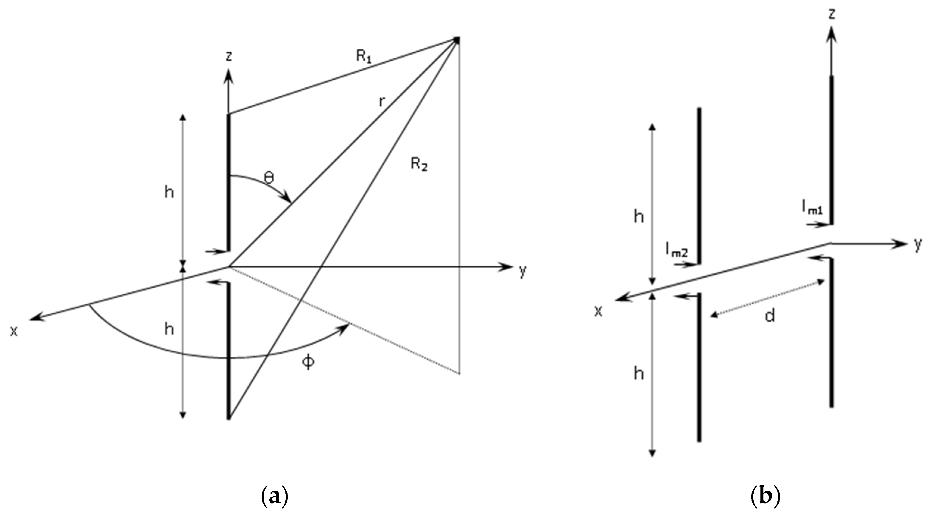
Figure 1. Geometry of the antenna models. (a) Equivalent dipole of length 2h and (b) equivalent two-dipole array.
Applsci 12 06525 g001
Figure 2. The orientation of a building with reference to the antenna. The building is modeled as a wire-grid rectangular parallelepiped.
Applsci 12 06525 g002
Figure 3. (a) Horizontal and (b) vertical cross-section of the configuration depicted in Figure 2.
Applsci 12 06525 g003
Figure 4. Radiation patterns of the monopole in free space (black, solid curve) and in the presence of a building with L = 10   m 0.05 λ and W = 10   m 0.05 λ . Three different heights H are considered (dashed and dotted curves, as indicated in the upper right corner). The distance between the antenna and the building is R = 100   m 0.5 λ . (a) φ -plane and (b) θ -plane.
Applsci 12 06525 g004
Figure 5. The same as Figure 4, except for the distance between the antenna and the building ( R = 200   m λ ). (a) φ -plane and (b) θ -plane.
Applsci 12 06525 g005
Figure 6. Radiation patterns of the monopole in free space (black, solid curve) and in the presence of a building with L = 60   m 0.3 λ and W = 10   m 0.05 λ . Three different heights H are considered (dashed and dotted curves, as indicated at the upper right corner). The distance between the antenna and the building is R = 100   m 0.5 λ . (a) φ -plane and (b) θ -plane.
Applsci 12 06525 g006
Figure 7. The same as Figure 6, except for the building size ( L = 10   m 0.05 λ and W = 60   m 0.3 λ ). (a) φ -plane and (b) θ -plane.
Applsci 12 06525 g007
Figure 8. θ -plane of the radiation patterns of the monopole in free space (black, solid curve) and in the presence of two buildings 30 × 10 × H   m 3 . Three different heights H are considered (dashed and dotted curves, as indicated at the upper right corner). The distances between the antenna and each building are (a) R = 100   m 0.5 λ and (b) R = 200   m λ .
Applsci 12 06525 g008
Figure 9. Radiation patterns of the array in free space (black, solid curve) and in the presence of a building with L = 50   m 0.168 λ and W = 10   m 0.034 λ . Three different heights H are considered (dashed and dotted curves, as indicated at the upper right corner). The distance between the antenna and the building is R = 100   m 0.336 λ . (a) φ -plane and (b) θ -plane.
Applsci 12 06525 g009
Table 1. Comparative synopsis of studies dealing with the effect of buildings on antenna radiation.
StudyFrequency RangeAntenna ModelBuilding ModelMethodPurposeMain Results-Conclusions
[12]MF (990 kHz)T-type, 60 m in heightλ/4 parasitic monopole or infinite-long PEC cylinderReciprocity or dyadic Green’s function techniqueImpact of building on radiation pattern and field intensityDecrease in field intensity up to 2.3 dB.
The radiation pattern is mostly affected by the height of the building.
[11]MF (990 kHz)λ/2 dipolePEC, three different heights consideredFinite difference methodImpact of buildings on the far fieldThe reduction in field intensity around a building may be up to 8.4 dB (building 30 m high, 100 m from the antenna), while the field variation becomes negligible 400 m from the antenna.
[2]HF (2–30 MHz)Logical periodic dipole antenna (LPDA)Rectangular parallelepiped (mesh of metallic wire segments and triangles)Full-wave simulation software package (FEKO)Impact of buildings on radiation pattern, gain, VSWR.Only the radiation pattern (among gain, VSWR, impedance) is affected by building blockage. The impact on patterns is greater if the size or height of the blockage is larger than λ/2.
[15]HF12-element (cross-loop antenna) circular arrayActual buildings (bodies of concrete or wood of appropriate size/shape)Commercially available software (FEKO)Impact of buildings on direction finding (DF)The antenna response changes due to the presence of buildings, resulting in estimation error of the DF system (up to 1° for the azimuth and 7° for the elevation).
[13]-2-element broadside or endfire arrayInfinite-long conductive or dielectric, rectangular cylinderMoM and unimoment methodImpact of building on radiation pattern and field intensityDeviation of the direction of the principal radiation lobe and production of side lobes, depending on the distance between the antenna and the building and the permittivity and size of the building.
[6]2.45 GHzRectangular patch antennaComplex wall structuresCommercially available software (CST Microwave Studio)Impact of walls on the radiation characteristics of access-point antennasThe radiation pattern is distorted (compared to the free-space pattern) when the antenna is mounted on complex wall structures, especially corners.
[29]30 MHz–1 GHzElectric dipole inside the buildingWire-grid bodyMoMDerivation of EM field distribution in and around buildingsThe calculated results were validated through measurements and the resonant characteristics of the building were determined.
[4]0.75–5 GHzHorn antennaSingle solid-metal cylinder or a set of such cylindersNumerical simulation (by using the tool Ansoft HFSS)Design of the appropriate cloak to reduce the blockageThe (uncloaked) objects produce strong sidelobes to the antenna’s radiation pattern (compared to free space) and decrease its directivity.
Current studyMF (1494 kHz & 1008 kHz)Monopole and 2-element arrayRectangular parallelepiped (wire-grid body)Point-matching solution and custom computer codeImpact of buildings on radiation patternThe height is the most important parameter that determines whether other parameters of the buildings affect the radiation pattern considerably. The impact on the radiation pattern is significant if the height of the building is greater than 0.3 λ .
Publisher’s Note: MDPI stays neutral with regard to jurisdictional claims in published maps and institutional affiliations.