Abstract
Precise control of casting velocity and effective throwing kinetic energy conversion efficiency in blasting engineering are challenges. To provide a theoretical basis and reference for the implementation plan and fine construction of the cast blasting project, we study the problems of casting velocity and energy consumption ratio of broken rock under the impact load of explosions in this manuscript. The calculation methods of casting velocity and throwing energy of broken rock under two blasting modes of spherical charge and cylindrical charge are established by using the theory of dimensional analysis and rock breaking by blasting. A large number of model tests are carried out by using high-speed photography. The results indicate that the casting velocity of broken rock after explosive initiation has two evident stages: instantaneous acceleration to a certain value and subsequent fluctuation; the velocity presents an ordinary distribution law with the step height, and the fitting correlation of high-speed photography results is more than 91%. With the minimum burden increasing from 0.12 m to 0.2 m, the energy consumption decreases from 1306.88 J to 747.49 J and the proportion of energy consumption decreases from 14.77% to 8.45%.
1. Introduction
With the modern development of large-scale construction equipment and industrial technology, engineering blasting is developing in a large-scale, intelligent, and refined direction. The most significant characteristics and advantages of cast blasting technology is that the technology uses the explosive energy of industrial explosives to break the rock mass. At the same time, the blasted rock mass was also thrown directly to the designated location, which remarkably reduces the cost of mechanical transportation. Since its inception, it has been widely used in civil construction projects such as transportation road foundations, hydropower dams, and extensive surface mine stripping. This technology can achieve the purpose of cofferdams and dam construction (Zheng M.C. et al. [1]). Likewise, the technology can be used to strip surface rock strata in open-pit mining (Li X.L. et al. [2]). In general, cast blasting technology is widely used in on-site engineering. Cast blasting is often used in coal mining, and its purpose is to fill the goaf with blasted rock. The key to the success of cast blasting technology lies in casting velocity. Because the explosion process has the characteristics of an instantaneous and high-energy extreme state, studies on the precise control of casting velocity and the statistical and influence factors of effective throwing kinetic energy conversion efficiency are recognized as challenges.
In recent years, in terms of blasting energy distribution, Blair D.P. [3,4] found that the linear superposition of vibration waves and the law of charge weight scaling are no longer applicable in special cases (extensive strain and viscoelastic medium). The rationality of the nonlinear superposition model and the elastic medium model is demonstrated through analysis. Zong Q. et al. [5] systematically analyzed the mechanisms of reflection and refraction in the energy transmission of explosive rock fragmentation. A relevant calculation formula was established to explore the variation law of blasting energy transfer efficiency under different charging methods. He M.C. et al. [6] obtained the fractal characteristics and energy consumption mechanism of rock blast cutting by impact and rock blast tests. Singh P.K. et al. [7,8,9] considered that vibration is a form of explosive energy and studied the vibration impact caused by the explosion energy on the residential structure and the underground part of an open-pit mine to determine the safe vibration threshold and blasting energy control measures. To predict ground vibration caused by multi-hole blasting energy, Agrawal H and Mishra A.K. [10,11] used scaled distance regression analysis and signature hole analysis. Finally, experiments were carried out to prove that the proposed method improves prediction accuracy. Through the water jet test, Ding C.X. et al. [12] found that the energy of the blasting gas and the blasting stress wave accounted for about 64% and 36% of the total energy produced by the explosion. Goto A. et al. [13] simulated volcanic explosions through field explosion experiments. This confirmed that scaled depth, the depth divided by the cube root of energy, is the main parameter determining the properties of explosive volcanism. The above studies have carried out research on blasting energy from different perspectives. However, many studies are qualitative and not specific enough. In practical engineering, accurately obtaining the proportion of the throwing kinetic energy is the key to quickly optimizing the blasting parameters. In the field of blasting, there is an urgent need for research on accurate calculation of throwing kinetic energy.
In terms of model testing, Li J.X. et al. [14] used a model to pour the specimens and combined it with the Hopkinson pressure bar to study the strength and failure mode of the filling body. G. Morales-Alonso et al. [15] used cement pouring model samples to carry out the tests, combined it with the constitutive model to verify the test results, and finally obtained the softening curve. Shan R.L. et al. [16] carried out blasting model tests and systematically studied the cutting blasting effect. Ma Q.Y. et al. [17,18] designed several sets of blasting model tests and a blasting plan ensuring the cutting effect was obtained. Liu D.W. et al. [19,20] conducted rock-like material model tests, and the non-linear change law of rock mass damage and the advantages of V-shaped grooves were proposed. Qiu J.D. et al. [21] carried out a physics model test to simulate the blasting disturbance on the underground tunnel. Through a series of physical model tests, Zhai C.C. et al. [22] found that fire caused the capacity of reinforced concrete structures to withstand explosive loads to decrease. Ge J.J. and Xu Y. [23] developed a transparent hard rock-like material used for blasting model tests. Zhang Z.X. et al. [24] conducted research through high-speed photography technology and gave test suggestions for the additional interface problem of small-scale model blasting. Sun W et al. [25,26,27] studied the backfill samples after demolding; they used X-ray and other means to study the mechanical properties of fillings with different lithological compositions. Through the above literature, we found that there are few studies using model tests to study casting velocity. Model testing is a commonly used method in the research field, and it is suitable to use it to study casting velocity and throwing contour.
For throwing blasts: Dumakor-Dupey N.K. et al. [28]’s refining article found that only about 20–30% of the blast energy released is utilized to fragment and throw the material. Cheng K. et al. [29] discussed in detail the calculation method of flying rock distance in deep hole blasting. Li X.L. et al. [30] and Murthy V.M.S.R. et al. [31] used a neural network to predict the throwing effect of bench blasting. Huang Y.H. et al. [32] studied blasting fly-rocks from three aspects: theoretical analysis, model testing, and numerical simulation, and finally obtained a method that can estimate the throwing distance of fly-rocks. Raina A.K. et al. [33,34,35] launched a series of studies on the fly-rock problem in throwing blasting. Aiming at the difficulty in throwing rock fragments from traditional cut blasting, Zhang H et al. [36] proposed and demonstrated an advanced blasting technology. Schneider J.M. et al. [37] presented the results from shock-tube experiments of single-span masonry walls subjected to dynamic blast loads characteristic of far-field explosions and free-field blast propagation. Hudaverdi T. and Akyildiz O [38], Bhagat N.K. et al. [39], and Rad H.N. [40] each proposed a new method to predict the distance of fly-rocks in throwing blasting. According to the above summary, the goal of much research on throwing blasting is throwing distance. However, the most critical factor affecting the throwing effect is the initial velocity of the rock breaking. Further research is needed on how to precisely control the casting velocity.
In terms of the blasting calculation method, Liang Q.G. [41], Liu Guofeng [42], and Yang R.L. [43] proposed methods for damage and vibration problems in the process of blasting and tunneling. Sanchidrian J.A. [44,45] used image analysis programs to measure burst fragments and dimensional analysis to describe the blasting fragmentation problem. Xu X.D. [46] proposed a fractal dimension calculation method related to the particle blockiness of broken rock. Guo J. et al. [47] and Chandrahas N.S. et al. [48] conducted research on the extreme gradient boosting algorithm; its advantages compared with other algorithms in blasting vibration velocity prediction were explored. Refinement and optimization of random forest algorithms was conducted by He B. et al. [49].
In conclusion, many calculation formulas cannot be applied well to practical engineering. A calculation method with clear terms of use and accurate prediction results needs to be studied.
In on-site engineering blasting, whether chamber cast blasting or step cast blasting, the minimum burden is one of the most critical factors influencing and determining the throwing effect. Throwing kinetic energy can play an important role in addressing the issue of measuring blast quality. However, it is directly related to the model-based test conditions of initial casting velocity and throwing efficiency. There are few related studies and results about the variation mechanism of casting velocity and throwing energy and accurate energy consumption under different burdens during blasting.
Velocity has been the subject of many classic studies in the field of blasting. The development of high-speed photography technology brings the possibility of accurately obtaining the casting velocity. Much uncertainty still exists about the relationship between burden and velocity. This study seeks to obtain data that will help to address these research gaps.
Because of the above reasons, it is found that the advantages of cast blasting are high construction efficiency, low use cost, and transportation cost savings. Determining its throwing efficiency is casting velocity and throwing energy consumption. Therefore, using the method of dimensional theory, high-speed photography techniques, and throwing blast model tests in this manuscript, calculation methods of casting velocity and throwing energy are proposed. The purpose of this paper is to study the variation mechanism of casting velocity and throwing energy under different burden conditions. This study has significance for improvement the cast blasting theory and its technical application in large-scale engineering.
2. Construction of Theoretical Calculation Model of Blast Throwing Energy
2.1. Casting Velocity Dimension
According to Livingston’s theory and classical bursting funnel theory, when a cartridge explodes within the “critical” burial depth, rock crushing presents a “bulging-acceleration-uniform velocity-free fall” motion process; the maximum velocity of detachment from the rock layer is the initial casting velocity. It is an essential factor influencing the effectiveness of cast blasting. The initial casting velocity factors are mainly rock properties, explosive properties, and blasting programs. Rock properties include rock density, compressive strength, tensile strength, elastic modulus, etc. Explosive performance contains explosive density, explosive burst velocity, explosive quantity, etc. Firstly, we use the similarity theory to derive the similarity criterion for cast blasting. Secondly, we perform dimensional analysis of casting velocity. Finally, the nine control variables above are determined. The basic parameters are the burden W, density ρr, and tensile strength σt, and the remaining six are collated using dimensionalization. The control parameters affecting the initial casting velocity are represented by the equation of dimensionality consisting of six πi terms, as shown in Table 1.

Table 1.
Parameters related to initial casting velocity.
Transforming π4 using π-theorem, we obtain:
The dimensionless function is obtained as:
Namely:
2.2. Calculation Model of Spherical Cartridge Throwing Energy
Provided that the explosive and rock properties remain unchanged and only the burden is considered in the blasting program, for spherical cartridge blasting, Equation (3) can be transformed into:
According to the theory related to Livingston’s bursting funnel, a power function is applied to the above equation, expressed as:
where v is the maximum initial velocity of the spherical cartridge throw; , k, α1 are factors related to the rock and explosive properties, and k, α1 can be obtained by a linear fit.
Using the micrometric division method, taking the cone unit body in the rocks between the cartridge depth and the free surface, the angle of the radian angle is α, as shown in Figure 1. From Newton’s theorem of motion, the instantaneous equation of motion of the unit during acceleration is:
where P is the pressure to which the unit is subjected; throughout the explosion, the unit is subjected to pressure by the explosion shock wave, stress waves, and explosive gas composition. The pressure its changes with time and can be seen as a function of time, which is denoted by P(t); S is the area of the unit under pressure, S = π(rα/2)2 (when α < 5°, sinα = α, and rα = L). A function of time is denoted by r(t). m is the mass of the unit, m = πρrWi(αWi/2)2/3. a is the acceleration, which is denoted by dv/dt. Equation (6) can be expressed as:
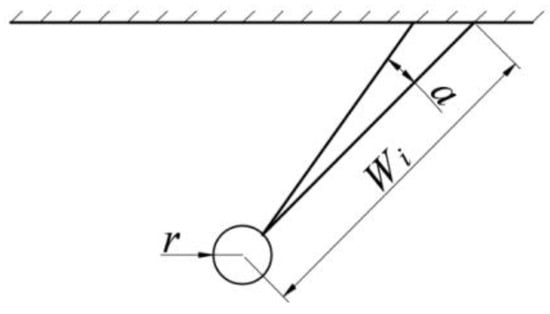
Figure 1.
The unit of throwing blast.
Simplification yields.
Suppose a particular unitary i starts accelerating at time point t0; at time point t, the initial casting velocity is reached. The initial casting velocity equation of the unitary body is obtained after the integral variation of Equation (8):
When the unit is in the direction of the minimum burden, Wi = W and the calculation equation is:
Combining Equations (8)–(10) yields the initial cast velocity equation for any unitary rock within the blast funnel range.
Equation (11) is the model for calculating the initial velocity of a spherical cartridge blast funnel throw when only considering the burden. The model uses the prerequisites of assuming a continuous rock medium and unchanged explosive properties.
2.3. Column Charge Blast Throw Energy Calculation Model
In actual engineering, chamber blasting, step-throw blasting shell holes, and explosives distribution show columnar characteristics. Based on the model for calculating the initial velocity of spherical cartridge blast throwing in the previous section, the columnar explosive rolls can be regarded as composed of n spherical cartridges along the axial direction of the blast hole. Similarly, the rock mass from the blast hole to the free surface in the step is divided into λ units, as shown in Figure 2. Based on the principle of energy conservation and assuming that the initial casting velocity and kinetic energy induced at a point j of a unit in the free surface are constituted by the joint action of n spherical cartridges, the initial casting velocity induced by a divided spherical cartridge i is vij. The model for calculating the magnitude of the casting velocity at point j can be expressed as:
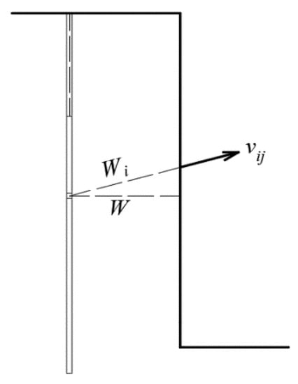
Figure 2.
Velocity vector diagram.
According to Equation (12), the equation for generating the initial casting velocity vij of the i-th cartridge at unit j point can be expressed as:
According to Equations (12) and (13), the initial casting velocity of unit j point can be calculated as:
When the unit is detached from the rock, the maximum casting velocity reached is considered as the initial casting velocity. The kinetic energy available at this point is considered as the throwing kinetic energy. Assuming that the weight of unit j point is m, the equation for calculating the kinetic energy of throwing is:
From Equations (14) and (15), it follows that:
Summing up the throwing kinetic energy of all the units in the whole step, the kinetic energy of the step rock-throwing caused by the charge explosive can be obtained as:
The exact prerequisites used in this throwing energy calculation model assume that the rock medium is continuous and the explosive properties are unchanged. For the unknown parameters k and α in the computational model, blasting model tests with multiple burdens of length W and charge quantity Q/n were carried out under the prerequisite assumptions. The experimental data were analyzed and fitted to obtain the results.
Given the existence of different rock media on the step surface in actual engineering, introducing the influence variables of rock density and step height divides the step rock in the blasted area into several micro-elements. Its thickness is dh, the distance from a microelement to the bottom of the step is h, and the density is ρr, as shown in Figure 3. Given differences in the initial casting velocity of a micro-element at different locations in step blasting, its functional relationship is supposed as follows:
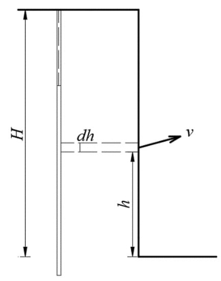
Figure 3.
Profile micrometer body.
Similarly, assuming the micro-element density as a function of step height is:
Then the equation for calculating the throwing kinetic energy of a micro-element with the height of h can be expressed as:
where is the hole distance. The equation for calculating the kinetic energy of step blasting throwing for all micro-elements to transform the entire step height integrally is:
Assume that the density of each micro-element and the casting velocity do not change with the height h. The above equation can be integrated to obtain the calculation equation for the throwing kinetic energy:
where λ is the number of micro-elements.
3. The Model Test
The model test method is one of the more practical ways of blasting verification. This method is particularly useful in studying blasting crater and throw blasting.
3.1. Test Program
Considering that the primary conditions in the calculation method are casting velocity and throwing energy, the model test studies the effect of the minimum burden on the casting velocity and throwing energy. Therefore, the minimum burden is selected as the only variable. The explosive quantity, hole diameter, charge length, collar distance, model material ratio, and related physical and mechanical parameters are assumed to have consistent invariant conditions. Three models were concreted for each test group, taking the average of the results as the analysis data to reduce experimental system errors. The minimum burden selects five cases of 0.12 m, 0.14 m, 0.16 m, 0.18 m, and 0.20 m for model tests.
The model was concreted with Portland cement materials. The model aggregate adopts quartz sand with a particle size of 0.35 mm to 0.5 mm, proportioned with a mass ratio of cement, quartz sand, and water of 1:5:1. According to the third similarity theorem: “For the same type of physical phenomenon, if the single-valued quantities are similar, and the similarity criteria constituted by the single-valued quantities are equal in numerical value, the phenomena are similar”, the geometry and boundary conditions both satisfy the single value condition in the blasting model test. It is necessary to meet the non-minimum burden and have a surface without cracks and damage regarding the size and boundary effects. According to experience, the requirements are satisfied when the blast hole’s distance to the non-minimum burden’s direction is greater than 1.5 times the minimum burden. The specific dimensions are: length 0.60 m, width 0.60 m, height 0.65 m, and blast hole diameter 10 mm. In addition, there are more than three models for each burden to ensure that there are enough data samples after excluding the apparent error data. The model is concreted at once to ensure that the mechanical properties of different model materials are consistent. After the model is made, it is wet-cured for 7 days. Then, it is cured in a natural environment for 28 days, with the test conducted after confirming that there are no cracks on the model’s surface, as shown in Figure 4.
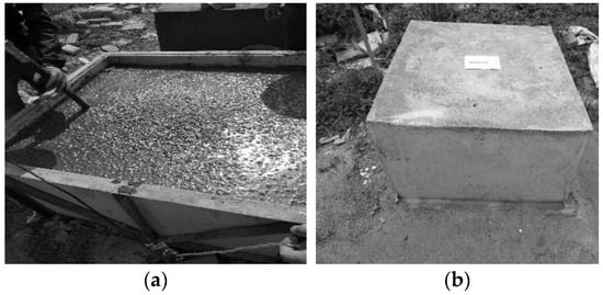
Figure 4.
Test model: (a) model concreting process, (b) individual models.
3.2. Making Models and Testing the Mechanical Properties of Materials
When concreting the model, 15 cube specimens with a side length of 0.10 m were concreted in the same proportion as the model material; the maintenance method and process are the same as that of the model. In terms of basic mechanical properties of materials, the static test system of Kunming University of Science and Technology was used to carry out basic mechanics tests, as shown in Figure 5. The model material’s density, uniaxial compressive strength, longitudinal wave velocity, and Poisson’s ratio were tested, as shown in Table 2.
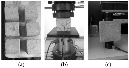
Figure 5.
Division diagram of explosion cavity: (a) standard specimens, (b) compression test, (c) acoustic testing.

Table 2.
Physical and mechanical parameters of materials.
3.3. Blasting Parameters
When carrying out model tests at the test site of the state-owned An Ning Chemical Plant in Kunming City, Yunnan Province, the model was concreted with geometric dimensions of 0.6 m in length and width and 0.65 m in height. At the same time, blast holes were reserved. The length of the blast hole consists of two parts: the length of the charge and the collar distance. The collar distance is the same as the minimum burden. Explosives use a 6 mm diameter detonating cord. The core of the explosives is hexogen; the charge quantity per meter is 25 g with a length of 0.04 m and an explosive quantity of 1 g. Explosive performance parameters are shown in Table 3. The detonator is a No. 8 industrial detonator; its length is 0.065 m and it contains 0.58 g of high explosive. The specific blasting parameters are shown in Table 4. Tests were carried after the model was maintained, and five blast model tests of burden were conducted. The reverse detonation method was adopted at the bottom of the hole.

Table 3.
Explosive performance.

Table 4.
Parameters of blasting.
The model test was conducted at the Anning Chemical Plant of Yunnan Civil Explosive Group. Blast holes were preset when concreting the model. The hole depth is charge length, detonator length, and collar distance. The length of the detonator is 0.065 m, the charge length is 0.04 m, and the collar distance is equal to the minimum burden. In order to increase the friction force of stemming, we used gypsum for packing. The detonating cord of industrial explosives is made of hexogen, and its charging quantity is 25 g per meter. Explosive performance parameters are shown in Table 3.
The blasting scheme is as follows. The test uses 1 g of high-energy detonating cord (length 0.04 m) as the cartridge; its aspect ratio is 4. We detonated the detonating cord using an industrial detonator No. 8 (500 mL explosive power); one detonator contains 0.60 g ± 0.01 g PETN, it is converted into 0.58 g hexogen using the explosive power.
3.4. Survey Program
High-speed photography was used to capture images during the rock-throwing process. The high-speed camera model is Hotshot1280CC/MIC, as shown in Figure 6. The shooting frequency is set to 1000 frames/s with a 0.05 m × 0.05 m grid as the background, as shown in Figure 7.
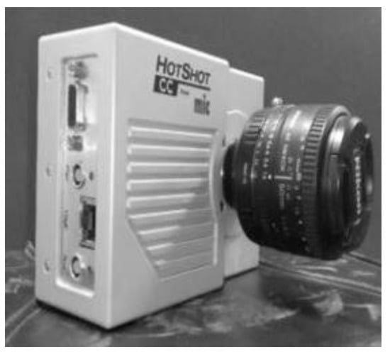
Figure 6.
High-speed camera.
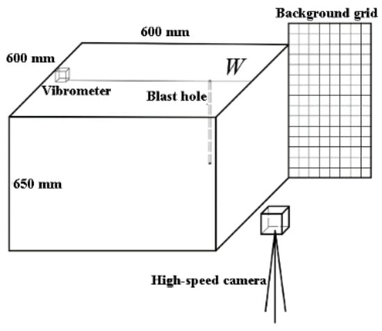
Figure 7.
Test diagram.
4. Discuss Test Results
4.1. Throwing Process
The rock bulge and throwing motion patterns at different time points after detonation were obtained for each of the five burden cases during the model test. Only the motion pattern of Model 1 is listed, and the minimum burden is 0.12 m every 4 ms, as shown in Figure 8.
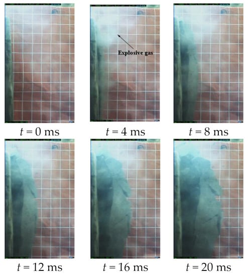
Figure 8.
Space position of rock at different time.
It can be seen that cracks appear in the rock when t = 4 ms. This indicates the presence of a small amount of explosive gas. The rocks produce significant displacement of about 0.025 m. When the broken rock moves to about 20 ms, almost no new cracks are produced in the broken rock. At this time, the free surface rock moves to the fifth grid, about 0.25 m from the original free surface, and it can be considered that the initial casting velocity has been reached. After that, the rock presents a free-fall motion with initial velocity under the gravity effect, and the entire throwing process lasts 1500 ms to 2000 ms. The throwing process of the other four burdens is identical to it except for the specific velocity.
4.2. Casting Velocity Analysis
4.2.1. Casting Velocity Distribution Mechanism
We utilized the previously built calculation method to obtain the initial casting velocity and throw kinetic energy. Then, we divided the broken rock into 20 micro-elements along the axial direction of the blast hole. We took the midpoint of each micro-element as the characteristic point. Finally, a relative coordinate system was constructed with the background grid as the size reference, as shown in Figure 9. At the same time, we used the tracking function of hotshot/cc processing software to track and capture the characteristic points of different models. Finally, on the basis of conducting five burden model experiments, the position and shape of the bulge movement of the free-face rock for every millisecond in the 0 ms to 19 ms period were obtained, as shown in Figure 10.
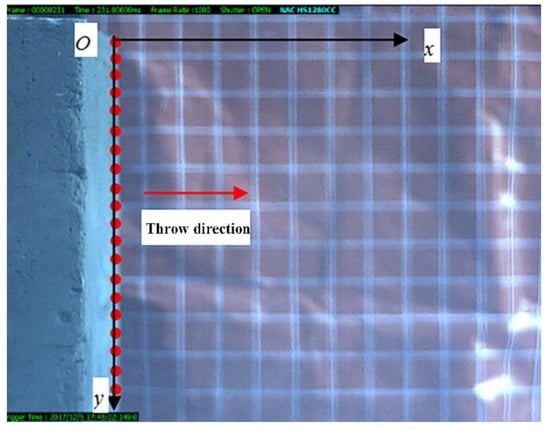
Figure 9.
Relative coordinate system.
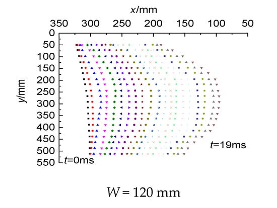
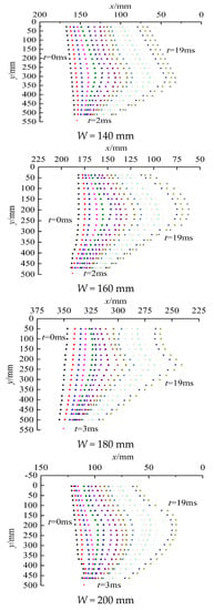
Figure 10.
Spatial distribution of particle positions.
Due to the differences in the initial bulging time in different burden situations, the first-millisecond morphology of Models 2 and 3 and the first and second-milliseconds morphology of Models 4 and 5 are not presented.
From the high-speed photography process and the analysis results in Figure 8, Figure 9 and Figure 10, it can be seen that the start of cracking and bulging movements in the free surface rock is about 2 to 3 ms after explosive detonation. With time, the displacement of the rock movement in the middle of the step is more extensive than in the upper and lower ends. The overall movement morphology is convex in the middle and low at both ends. This indicates that the rock in the middle part moves faster than at the two ends.
To accurately obtain the rock casting velocity, the spatial position relationship of the different models in the model test at different time points thrown rocks is calculated using the following equation:
where vjt is the velocity of the mass point j at the time point t, m/s; (xt−1,yt−1) and (xt,yt) are the coordinate positions at time t − 1 and time t, respectively. Aiming at the fluctuation of broken rock in the process of throwing, the maximum velocity is chosen as the casting velocity in the calculation model. The specific calculation equation is:
Figure 8 and Figure 10 show the real spatial motion law of blasting broken rock obtained from the high-speed photography. According to Equation (23), the space–time relations of the five burden-free surface broken rock masses at different moments are calculated. When the broken rock on the free surface reaches the initial casting velocity, the distribution law of the casting velocity of broken rock masses at different step heights is thus obtained. The experimental values of the mass velocity distribution are shown in Figure 11.
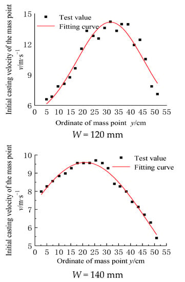
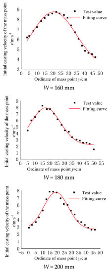
Figure 11.
Spatial distribution of particle velocities.
Where the maximum casting velocity occurs in five burdens, using the Equation (24), the relationship between the velocity of the particle and the time is obtained, as shown in Figure 12. Calculation results show the following.
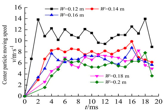
Figure 12.
Time history curve of the velocity of the center particle.
- (1)
- In addition, a comparative analysis of the bulge morphology of each model reveals that the timing of the initial bulge movement varies among models; the bulging time of Model 1 is about 1 ms, while Models 2 and 3 are about 2 ms, and Models 4 and 5 are about 3 ms. This indicates that as the minimum burden increases, the penetration time of the blast crack will be delayed and the free surface bulge start time is lagging. During the same movement time, the displacement of the broken rock on the free surface decreases with the increase of the burden. This indicates that the casting velocity shows a decreasing trend with the increasing burden;
- (2)
- The time from the beginning of the bulge to the completion of the initial acceleration is between 2 ms to 6 ms. Afterward, the casting velocity fluctuates due to the explosion of overflowing gas and collisions between broken bodies, etc. The peak value of the initial casting velocity shows a clear downward trend with the increasing burden.
The velocity values and distribution characteristics of the masses at different step heights can be observed. The casting velocity value was found to be along the step vertically, showing a trend of increasing first and then decreasing, which satisfies the characteristics of the normal distribution function. The normal distribution function is:
The above equation and the principle of least squares are used to fit the function relationship between the casting velocity and the height of the step. The normal distribution function relationship between the initial casting velocity of five burden models and the y coordinate value (step height) is obtained. The fitting parameters are shown in Table 5. The image of the fitted function is shown in Figure 11. The fitting results show that the fitting correlation is above 91%. Among them, the correlations between the experimental fitting results of the No. 4 and No. 2 models are as high as 98% and 99%. The fitting parameters are very reasonable and can truly reflect the test results.

Table 5.
The function relationship between the initial casting velocity of the particle and the y-coordinate value.
4.2.2. Throwing Kinetic Energy Distribution Law
For model tests, the blasting medium is artificially concreted plain concrete, regarded as a homogeneous medium regardless of density. Then, let ρ(h) = ρ; the overall blasting muck pile quality is determined by statistics after the explosion, taking the actual statistical result M as the benchmark. At the same time, it is assumed that the distribution is uniform in the y-direction; the vertical coordinate value y is used instead of the height along the step. The coordinates of the upper and lower masses are denoted by ymax and ymin, respectively. Then, the equation for calculating the kinetic energy of throwing can be transformed by Equation (20), shown as follows.
where v(y) is obtained by fitting the high-speed photography results of the step test using the numerical difference method for the 20 micro-elements along the step direction in the model test. The specific calculation equation of throwing kinetic energy can be transformed into:
By substituting the functional relationship in Table 5 into Equation (27), each model’s kinetic energy blasting throwing is calculated, as shown in Table 6.

Table 6.
Model throwing kinetic energy.
According to the specific calculation of the throwing energy in the model test, the energy used to throw the broken rock mass during the explosion shows a significant downward trend with the increasing burden. When the minimum burden is 0.12 m, the throwing energy consumption is 1306.88 J. When the minimum burden increases to 0.20 m, the energy consumption of rock-throwing is 747.49 J, which is reduced by 0.57 times when the minimum burden is 0.12 m. This shows that the change of the minimum burden greatly affects the energy consumed by throwing broken rocks. With the increase of the minimum burden, the breaking time and the breaking range of the rock explosive energy also increase. Therefore, more energy is used to break the rock. The kinetic energy of explosives used for throwing has a significant decrease in the proportion of explosive energy, as shown in Figure 13. By fitting the relationship between the minimum burden and the throwing energy consumption, we obtain the power function relationship between them.
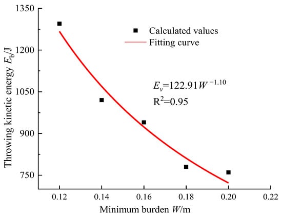
Figure 13.
Relation of the thrown kinetic energy with the minimum burden.
At the same time, the following equation is used to calculate the proportion of energy consumed by broken rock throwing. The calculation results are shown in Table 6.
In the model experiment, the proportion of explosive energy used to throw broken rocks is between 8% and 15%. When the charge quantity is the same as the detonated medium, the throwing kinetic energy proportion decreases as the minimum burden increases. When the minimum burden is 0.12 m, the throwing kinetic energy proportion is about 15%. When the burden is 0.20 m, the throwing kinetic energy proportion is reduced to 8%. In practical engineering, the best burden can be determined according to the blasting muck pile morphology.
5. Conclusions
The casting velocity and throwing energy of rock fragments were calculated through blasting basic theory and dimensional analysis theory. In addition, combined with a large number of model tests, the variation law of the throwing energy of the broken rock mass with the burden under the explosive load of the explosive in the blast hole was obtained:
- (1)
- Based on dimensional theory, the calculation equations for the casting velocity and throwing energy of the rock fragments were constructed during spherical cartridge and step columnar cartridge blasting. Model tests verified the feasibility of the calculated equation;
- (2)
- Through high-speed photography technology, it was found that the casting velocity of rock in the broken zone of step blasting has different burdens. This shows a normal distribution law along the vertical direction of the steps, and the fit correlation is high;
- (3)
- The model experiment successfully obtained the energy consumption of throwing broken rocks under explosive load. This shows a decreasing trend with an exponential relationship with the increasing burden. The trend of the energy proportion is similar.
It is generally considered that the casting velocity and energy consumption of broken rock belong to the useless work of explosives to break the rock. It wastes energy and produces harmful conditions such as individual blasting fly-rock. However, cast blasting uses part of the energy to throw the broken rock mass to a fixed point, which saves a significant mechanical transportation procedures and costs. It can provide a reference for predicting throwing distance and energy consumption. The manuscript uses only the minimum burden as a single influencing factor. Many influencing factors such as lithology, charge structure, time difference of initiation, and so on are not involved. The law of multiple factors affecting the minimum burden, lithology, blasting parameters, and blasting technology needs further study.
Author Contributions
Y.H. led the experiment and wrote the first draft of the paper, Z.Z. (Zixiang Zhao) assisted the experiment and participated in the revision of the paper, Z.Z. (Zhiyu Zhang) gave valuable opinions on the work, J.Z. processed the experimental data, H.L. is responsible for coordinating and communicating with team members, Y.L. used data to draw charts. All authors have read and agreed to the published version of the manuscript.
Funding
This study was financially supported by the National Natural Science Foundation of China (52064025, 52164009, 52164010). Its support is gratefully appreciated.
Institutional Review Board Statement
Not applicable.
Informed Consent Statement
Not applicable.
Data Availability Statement
Not applicable.
Conflicts of Interest
We declare that we do not have any commercial or associative interest that presents a conflict of interest in connection with the work.
Nomenclature
| a | Acceleration |
| a1 | Hole distance |
| A | Fit coefficient |
| D | Explosive burst velocity |
| E | Modulus of elasticity |
| Ev | Throwing kinetics |
| Et | Explosive energy |
| k | Rock coefficient |
| L | Arc length, pressure area diameter |
| m | Unit mass |
| m1 | Fit coefficient |
| M | Blasting muckpile statistical quality |
| P | Pressure |
| Q | Explosive quantity |
| r | Unit radius |
| R2 | Correlation coefficient |
| S | Pressure area |
| v | Initial casting velocity |
| v(y) | Variation formula of casting velocity with ordinate |
| W | Minimum burden |
| y0 | Fit coefficient |
| α | Radian angle |
| α1 | Explosive coefficient |
| Fit coefficient | |
| π | Number π |
| πi | Similarity criterion |
| ρ, ρr | Rock density |
| ρb | Explosive density |
| σc | Compressive strength |
| σt | Tensile strength |
| λ | Number of micro-elements |
| Hv | Throwing kinetics ratio |
| ymax, ymin | Mass point coordinate |
References
- Zheng, M.C.; Liao, J.B. The practice of directional blasting for dam construction in the tailing pond of Dashipangu. Chin. J. Min. Technol. 2011, 11, 106–108. [Google Scholar] [CrossRef]
- Li, X.L.; He, L.H.; Luan, L.F.; Zhang, Z.Y. Simulation model for muckpile shape of high bench cast blasting in surface coal mine. J. China Coal Soc. 2011, 36, 1457–1462. [Google Scholar] [CrossRef]
- Blair, D.P. Non-linear superposition models of blast vibration. Int. J. Rock Mech. Min. 2008, 45, 235–247. [Google Scholar] [CrossRef]
- Blair, D.P. Blast vibration dependence on charge length, velocity of detonation and layered media. Int. J. Rock Mech. Min. 2014, 65, 29–39. [Google Scholar] [CrossRef]
- Zong, Q.; Meng, D.J. Influence of different kinds of hole charging structure on explosion energy transmission. Chin. J. Rock Mech. Eng. 2003, 22, 641–645. [Google Scholar] [CrossRef]
- He, M.C.; Wang, Y.; Su, J.S.; Liu, D.Q. Analysis of fractal characteristics of fragment of sandstone impact rock burst under static and dynamic coupled loads. J. China Univ. Min. Technol. 2018, 47, 699–705. [Google Scholar]
- Singh, P.K.; Roy, M.P. Damage to surface structures due to blast vibration. Int. J. Rock Mech. Min. 2010, 47, 949–961. [Google Scholar] [CrossRef]
- Singh, P.K.; Roy, M.P.; Paswan, R.K. Controlled blasting for long term stability of pit-walls. Int. J. Rock Mech. Min. 2014, 70, 388–399. [Google Scholar] [CrossRef]
- Singh, P.K.; Roy, M.P.; Paswan, R.K. Blast vibration effects in an underground mine caused by open-pit mining. Int. J. Rock Mech. Min. 2015, 80, 79–88. [Google Scholar] [CrossRef]
- Agrawal, H.; Mishra, A.K. Modified scaled distance regression analysis approach for prediction of blast-induced ground vibration in multi-hole blasting. J. Rock Mech. Geotech. 2019, 11, 202–207. [Google Scholar] [CrossRef]
- Agrawal, H.; Mishra, A.K. An innovative technique of simplified signature hole analysis for prediction of blast-induced ground vibration of multi-hole/production blast: An empirical analysis. Nat. Hazards 2020, 100, 111–132. [Google Scholar] [CrossRef] [Green Version]
- Ding, C.X.; Yang, R.S.; Lei, Z.; Chen, C.; Zheng, C.D. Experimental Study on Blasting Energy Distribution and Utilization Efficiency Using Water Jet Test. Energies 2020, 13, 5340. [Google Scholar] [CrossRef]
- Goto, A.; Taniguchi, H.; Yoshida, M. Effects of explosion energy and depth to the formation of blast wave and crater: Field explosion experiment for the understanding of volcanic explosion. Geophys. Res. Lett. 2001, 28, 4287–4290. [Google Scholar] [CrossRef]
- Li, J.X.; Sun, W.; Li, Q.Q.; Chen, S.; Yuan, M.L.; Xia, H. Influence of Layered Angle on Dynamic Characteristics of Backfill under Impact Loading. Minerals 2022, 12, 511. [Google Scholar] [CrossRef]
- Morales-A, G.; Cendón, D.A.; Gálvez., F.; Sánchez-G., V. Influence of the softening curve in the fracture patterns of concrete slabs subjected to blast. Eng. Fract. Mech. 2015, 140, 1–16. [Google Scholar] [CrossRef]
- Shan, R.L.; Huang, B.L.; Wei, Z.T.; Kong, X.S. Model test of quasi-parallel cut blasting in rock drivage. Chin. J. Rock Mech. Eng. 2012, 31, 256–264. [Google Scholar] [CrossRef]
- Ma, Q.Y.; Yuan, P.; Han, B.; Zhang, J.S.; Liu, H.X. Dynamic strain wave analyses of parallel cut blasting model tests for vertical shaft. Rock Eng. Rock Mech. Struct. Rock Masses. 2014, 190, 1159–1164. Available online: https://www.webofscience.com/wos/alldb/full-record/WOS:000345985300190 (accessed on 26 May 2014).
- Ma, Q.Y.; Yuan, P.; Zhang, J.S.; Ma, R.Q.; Han, B. Blast-Induced Damage on Millisecond Blasting Model Test with Multicircle Vertical Blastholes. Shock Vib. 2015, 2015, 504043. [Google Scholar] [CrossRef]
- Liu, D.W.; Zhang, J.J.; Tang, Y.; Jian, Y.H.; Cai, C.W. Damage Analysis of Concrete Structure under Multidirectional Shaped Charge Blasting Using Model Experiment and Ultrasonic Testing. Adv. Civ. Eng. 2021, 2021, 6677041. [Google Scholar] [CrossRef]
- Liu, D.W.; Tang, Y.; Cao, M.; Zhang, J.J.; Xu, Q.; Cai, C.W. Nondestructive testing on cumulative damage of watery fractured rock mass under multiple cycle blasting. Eng. Fract. Mech. 2021, 254, 107914. [Google Scholar] [CrossRef]
- Qiu, J.D.; Li, X.B.; Li, D.Y.; Zhao, Y.Z.; Hu, C.W.; Liang, L.S. Physical Model Test on the Deformation Behavior of an Underground Tunnel Under Blasting Disturbance. Rock Mech. Rock Eng. 2020, 54, 91–108. [Google Scholar] [CrossRef]
- Zhai, C.C.; Chen, L.; Xiang, H.B.; Fang, Q. Experimental and numerical investigation into RC beams subjected to blast after exposure to fire. Int. J. Impact Eng. 2016, 97, 29–45. [Google Scholar] [CrossRef]
- Ge, J.J.; Xu, Y. A Method for Making Transparent Hard Rock-Like Material and Its Application. Adv. Mater. Sci. Eng. 2019, 2019, 1274171. [Google Scholar] [CrossRef] [Green Version]
- Zhang, Z.X.; Chi, L.; Zhang, Q.B. Effect of Specimen Placement on Model Rock Blasting. Rock Mech. Rock Eng. 2021, 54, 3945–3960. [Google Scholar] [CrossRef]
- Sun, W.; Wang, H.J.; Hou, K.P. Control of waste rock-tailings paste backfill for active mining subsidence areas. J. Clean. Prod. 2018, 171, 567–579. [Google Scholar] [CrossRef]
- Sun, W.; Hou, K.P.; Yang, Z.Q.; Wen, Y.M. X-ray CT three-dimensional reconstruction and discrete element analysis of the cement paste backfill pore structure under uniaxial compression. Constr. Build. Mater. 2017, 138, 69–78. [Google Scholar] [CrossRef]
- Sun, W.; Wu, A.X.; Hou, K.P.; Yang, Y.; Liu, L.; Wen, Y.M. Real-time observation of meso-fracture process in backfill body during mine subsidence using X-ray CT under uniaxial compressive conditions. Constr. Build. Mater. 2016, 113, 153–162. [Google Scholar] [CrossRef]
- Dumakor-Dupey, N.K.; Arya, S.; Jha, A. Advances in Blast-Induced Impact Prediction—A Review of Machine Learning Applications. Minerals 2021, 11, 601. [Google Scholar] [CrossRef]
- Cheng, K.; Zhang, C.S. Inquiry into flyrock distance for deep-hole blasting. Chin. J. Rock Mech. Eng. 2000, 19, 531–533. [Google Scholar] [CrossRef]
- Li, X.L.; He, L.H. The High Bench Cast Blasting Effects of BP Neural Network Prediction Model Research. Dis. Adv. 2013, 6, 75–82. [Google Scholar]
- Murthy, V.M.S.R.; Kumar, A.; Sinha, P.K. Prediction of throw in bench blasting using neural networks: An approach. Neural Comput. Appl. 2018, 29, 143–156. [Google Scholar] [CrossRef]
- Huang, Y.H.; Mao, Z.L.; Zhang, Z.Y.; Li, X.H.; Yan, L. Building the intelligent transportation systems based on the computation of driving velocity law of blasting fly-rock. Cluster. Comput. 2019, 22, 759–768. [Google Scholar] [CrossRef]
- Raina, A.K.; Chakraborty, A.K.; Choudhury, P.B.; Sinha, A. Flyrock danger zone demarcation in opencast mines: A risk based approach. Bull. Eng. Geol. Environ. 2011, 70, 163–172. [Google Scholar] [CrossRef]
- Raina, A.K.; Murthy, V.M.S.R.; Soni, A.K. Flyrock in bench blasting: A comprehensive review. Bull. Eng. Geol. Environ. 2014, 73, 1199–1209. [Google Scholar] [CrossRef]
- Raina, A.K.; Murthy, V.M.S.R. Importance and sensitivity of variables defining throw and flyrock in surface blasting by artificial neural network method. Curr. Sci. India. 2016, 111, 1524–1531. [Google Scholar] [CrossRef]
- Zhang, H.; Li, T.C.; Du, Y.T.; Zhu, Q.W.; Zhang, X.T. Theoretical and numerical investigation of deep-hole cut blasting based on cavity cutting and fragment throwing. Tunn. Undergr. Space Technol. 2021, 111, 103854. [Google Scholar] [CrossRef]
- Schneider, J.M.; von Ramin, M.; Stottmeister, A.; Stolz, A. Characterization of debris throw from masonry wall sections subjected to blast. Eng. Struct. 2020, 203, 109729. [Google Scholar] [CrossRef]
- Hudaverdi, T.; Akyildiz, O. A new classification approach for prediction of flyrock throw in surface mines. Bull. Eng. Geol. Environ. 2019, 78, 177–187. [Google Scholar] [CrossRef]
- Bhagat, N.K.; Rana, A.; Mishra, A.K.; Singh, M.M.; Singh, A.; Singh, P.K. Prediction of fly-rock during boulder blasting on infrastructure slopes using CART technique. Geomatics Nat. Hazards Risk 2021, 12, 1715–1740. [Google Scholar] [CrossRef]
- Rad, H.N.; Bakhshayeshi, I.; Jusoh, W.A.W.; Tahir, M.M.; Foong, L.K. Prediction of Flyrock in Mine Blasting: A New Computational Intelligence Approach. Nonrenewable Resour. 2020, 29, 609–623. [Google Scholar] [CrossRef]
- Liang, Q.G.; An, Y.F.; Zhao, L.; Li, D.W.; Yan, L.P. Comparative study on calculation methods of blasting vibration velocity. Rock Mech. Rock Eng. 2011, 44, 93–101. [Google Scholar] [CrossRef]
- Liu, G.F.; Feng, X.T.; Feng, G.L.; Chen, B.R.; Chen, D.F.; Duan, S.Q. A method for dynamic risk assessment and management of rockbursts in drill and blast tunnels. Rock Mech. Rock Eng. 2016, 49, 3257–3279. [Google Scholar] [CrossRef]
- Yang, R.L. A new method to measure and calculate tri-axial static strain change based on relative displacements between points for rock mass and structure. Rock Mech. Rock Eng. 2020, 53, 23–30. [Google Scholar] [CrossRef]
- Sanchidrian, J.A.; Segarra, P.; Lopez, L.M. A practical procedure for the measurement of fragmentation by blasting by image analysis. Rock Mech. Rock Eng. 2006, 39, 359–382. [Google Scholar] [CrossRef]
- Sanchidrian, J.A.; Ouchterlony, F. A distribution-free description of fragmentation by blasting based on dimensional analysis. Rock Mech. Rock Eng. 2017, 50, 781–806. [Google Scholar] [CrossRef] [Green Version]
- Xu, X.D.; He, M.C.; Zhu, C.; Lin, Y.; Cao, C. A new calculation model of blasting damage degree—Based on fractal and tie rod damage theory. Eng. Fract. Mech. 2019, 220, 106619. [Google Scholar] [CrossRef]
- Guo, J.; Zhang, C.; Xie, S.; Liu, Y. Research on the Prediction Model of Blasting Vibration Velocity in the Dahuangshan Mine. Appl. Sci. 2022, 12, 5849. [Google Scholar] [CrossRef]
- Chandrahas, N.S.; Choudhary, B.S.; Teja, M.V.; Venkataramayya, M.S.; Prasad, N.S.R.K. XG Boost Algorithm to Simultaneous Prediction of Rock Fragmentation and Induced Ground Vibration Using Unique Blast Data. Appl. Sci. 2022, 12, 5269. [Google Scholar] [CrossRef]
- He, B.; Lai, S.H.; Mohammed, A.S.; Sabri, M.M.S.; Ulrikh, D.V. Estimation of Blast-Induced Peak Particle Velocity through the Improved Weighted Random Forest Technique. Appl. Sci. 2022, 12, 5019. [Google Scholar] [CrossRef]
Publisher’s Note: MDPI stays neutral with regard to jurisdictional claims in published maps and institutional affiliations. |
© 2022 by the authors. Licensee MDPI, Basel, Switzerland. This article is an open access article distributed under the terms and conditions of the Creative Commons Attribution (CC BY) license (https://creativecommons.org/licenses/by/4.0/).