Article

Virtual Reality-Based Interface for Advanced Assisted Mobile Robot Teleoperation

Instituto de Diseño y Fabricación, Universitat Politècnica de València, 46022 Valencia, Spain
*
Author to whom correspondence should be addressed.
Appl. Sci. 2022, 12(12), 6071; https://doi.org/10.3390/app12126071
Submission received: 12 May 2022 / Revised: 12 June 2022 / Accepted: 13 June 2022 / Published: 15 June 2022
(This article belongs to the Special Issue Trajectory Analysis, Positioning and Control of Mobile Robots)

Abstract

:
This work proposes a new interface for the teleoperation of mobile robots based on virtual reality that allows a natural and intuitive interaction and cooperation between the human and the robot, which is useful for many situations, such as inspection tasks, the mapping of complex environments, etc. Contrary to previous works, the proposed interface does not seek the realism of the virtual environment but provides all the minimum necessary elements that allow the user to carry out the teleoperation task in a more natural and intuitive way. The teleoperation is carried out in such a way that the human user and the mobile robot cooperate in a synergistic way to properly accomplish the task: the user guides the robot through the environment in order to benefit from the intelligence and adaptability of the human, whereas the robot is able to automatically avoid collisions with the objects in the environment in order to benefit from its fast response. The latter is carried out using the well-known potential field-based navigation method. The efficacy of the proposed method is demonstrated through experimentation with the Turtlebot3 Burger mobile robot in both simulation and real-world scenarios. In addition, usability and presence questionnaires were also conducted with users of different ages and backgrounds to demonstrate the benefits of the proposed approach. In particular, the results of these questionnaires show that the proposed virtual reality based interface is intuitive, ergonomic and easy to use.

1. Introduction

1.1. Motivation

The main area of this work is mobile robots, which play an increasingly primary role in our society. Due to rapid development of AI, powerful lithium batteries, and low-power microchips, mobile robots are becoming cheaper, available to more people, and introduced in various areas of life, taking more significant roles in society and removing labor-intensive jobs in such areas as rescue operations [1,2,3], space exploration [4,5,6], military application [7,8] industrial use [9,10,11], underwater exploration [12,13,14], and healthcare applications [15,16,17], among others.
While many approaches can be found in the literature regarding the automatic control and navigation of this kind of robot, most of the mentioned applications imply the interaction between humans and robots. This collaboration is usually done in such a way that the human guides the robot remotely while the robot navigates in a hostile and/or dangerous environment for the human. However, many approaches do not develop a natural and intuitive interaction for the human [18,19,20,21] and, hence, the resulting human–robot cooperation may be dismissed.
This paper develops a new virtual reality-based interface for mobile robot navigation in unknown scenarios, providing an intuitive and natural interaction for the user.

1.2. Literature Review

The main object of this work is the teleoperation of robotic systems, in general, and mobile robots, in particular. The teleoperation or remote control of robotic systems by humans has been deeply studied in the past decades [22] and is still an ongoing tendency in research. Robot teleoperation is carried out for many reasons: to operate in hazardous environments (e.g., radioactive zones [23,24], aerial zones [25,26], underwater areas [27,28], or in space [29]); to conduct accurate surgeries [30,31,32,33]; to perform rescue operations [34], etc.
Recently, advanced artificial intelligence (AI) techniques have facilitated the automation of many complex operations that previously had to be conducted using robot teleoperation. Nevertheless, there are still many robot applications that cannot be completely automated due to their subjectivity or complexity. However, these partially automated tasks can significantly benefit from human–robot cooperation by means of shared-control architectures [35]. In this sense, many contributions have been developed focusing on the human–robot interaction in teleoperation tasks [21,36,37,38,39,40,41,42], as is the case of this work.
Telepresence [22] provides the user with an interface which makes the direct control task less dependent on his or her skills and concentration. Telepresence for direct control teleoperation is a strong trend in recent research developments due to the introduction of visual interfaces [30], virtual and augmented reality [39], haptic devices [43], or a combination of them [31,40,44]. For example, the authors in [22] provided the user with an interface which makes the direct control task less dependent on his or her skills and concentration. The authors in [37] proposed an approach where one arm of a bimanual robot is teleoperated to grasp a target object, while the other develops an automatic task of visual servoing to keep the object in sight of a camera and avoid occlusions, thus making the teleoperation easier.
The success of telepresence lies directly upon the skills of the user who performs the teleoperation [9,45]. For this reason, many current approaches propose to incorporate constraints to avoid the user commanding the robot in a wrong way. For instance, in [32] virtual fixtures (i.e., virtual barriers) were included to automatically modify the reference position provided by the user in order to confine it within the allowed area. In [24,43], haptic devices were used to prevent the user from commanding reference positions beyond certain limits.
However, assisted teleoperation with telepresence interfaces and virtual barriers is still an ongoing research field due to its drawbacks, since the control is still held by the human [36]. In this regard, this article proposes to use the well-known potential field-based navigation method together with virtual reality devices to improve the current assisted teleoperation of mobile robots.

Virtual Reality-Based Interfaces

Technical advances in the development of virtual environments (VE) and virtual reality (VR) headsets and devices for the video games industry [46,47] or social media [48,49] have now made it possible to develop applications related to human–robot interaction. In particular, in mobile robot applications, some interesting works using VR can be found. For instance, the authors in [9] proposed an VR interface for training operators, who teleoperated the movement of a mobile robot with two arms for industrial pick-and-place tasks, and tested it with several users to determine the improvement obtained. Authors in [50] provided an approach to reduce the effects of time delays during the teleoperation based on VR and optimization data techniques. Authors in [51] developed a VR simulator that recreated a team of selective compliance assembly arms (SCARA) to include cloud resources to help users to improve the task performance. Authors in [52] presented an immersive SLAM-based VR system for the teleoperation of mobile manipulators in unknown environments. In this approach, the user totally guides the mobile robot, which is constrained into a limited area. A 3D real-time environment reconstruction map is shown in the VE, allowing the user to “see” the real environment.
The majority of the studies relating VR and the teleoperation of mobile robots are focused on improving the task performance (i.e., reducing the time needed to complete the operation, and incorporating real elements in the VE). However, to the best of the authors’ knowledge, few of them are focused on human–robot interaction aspects: interface ergonomics, quality of the interface, ease of interaction with virtual elements, interference of the virtual elements with the task target, etc. Note that the improvement of all these features, which is the main goal of this work, can be decisive for the success of the developed interface.

1.3. Proposal

This paper proposes a new virtual reality-based interface for the teleoperation of mobile robots in unknown scenarios. The proposed interface is designed to be natural and immersive to the user, reducing the learning process of the interface. The proposed interface is fully described in the article, and its efficacy is experimentally demonstrated using the mobile robot Turtlebot3 Burger. In addition, a complete study with users of different ages and backgrounds is detailed to determine the quality and usability of the proposed interface.
Concretely, this work presents several contributions as highlighted below:
  • Unlike the works mentioned above, this work presents an intuitive interface designed to teleoperate mobile robots in totally unknown environments. To do this, the user is able to guide the robot through the environment in order to benefit from the intelligence and adaptability of the human, whereas the robot is able to automatically avoid collisions with the objects in the environment in order to benefit from its fast response.
  • Contrary to the aforementioned works, the proposed interface does not seek the realism of the virtual environment but provides all the minimum necessary elements that allow the user to carry out the teleoperation task in a more natural and intuitive way. Hence, the proposed interface establishes different virtual elements (e.g., mobile robot, user reference, 2D map of the environment, information related to the robot or task, and the 3D position of the objects detected in real-time, among others) that allow the user to quickly interact with the interface and successfully perform the robot teleoperation task.
  • In contrast to the works about virtual reality interfaces mentioned above, where virtual reality controllers are used for interacting with the virtual environment, this work proposes the use of gamepads to carry out this interaction. Thus, this work aims to improve the ergonomics of the user, allowing them to teleoperate the robots in a natural way for long periods of time.
  • This work is focused on improving the interaction between human users and interfaces for the teleoperation of mobile robots. In this sense, in addition to conventional studies, similar to those carried out in the abovementioned works to establish the viability and efficiency of the proposed interface, this work also carries out a study of the experience lived by users of different ages, gender and backgrounds when using the proposed interface in order to establish its degree of naturalness and intuition.

1.4. Content of the Article

The content of the article is as follows. Section 2 describes the VR-based interface developed in this work. Subsequently, the interface functionalities, performance and effectiveness of the proposed VR-based interface are shown in Section 3 through experimental results. Moreover, the usability of the interface as well as other aspects are also studied in Section 3 through several questionnaires and tests conducted with users of different ages and backgrounds. Finally, some conclusions are outlined in Section 4.

2. Proposed Application
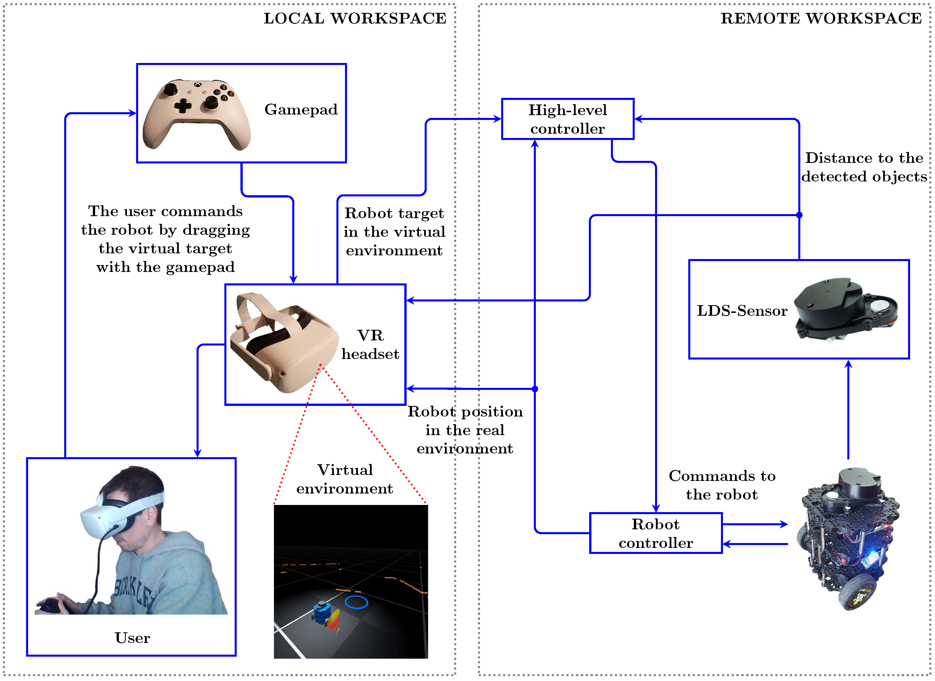
2.1. Overview

The application developed in this work consists of two workspaces: the local workspace in which the VR headset is used and the remote workspace in which the robotic system operates, as shown in Figure 1.
In the local workspace, the user is able to visualize the robot and its environment by wearing the VR headset. Without loss of generality, this work uses the Oculus Quest 2 VR headset [53], with a LCD screen with a resolution of 1832 × 1920 pixels per eye and refresh frequency of up to 90 Hz, 6 GB of RAM, and a Quadcomm Snapdragon XR2 processor. In addition, this device allows standalone applications.
In this work, the Unity Real-Time Development Platform [54] is used to develop the virtual environment. Hence, the real robot is modeled and included in the virtual world. The location of the detected obstacles in the virtual world is updated according to that of the corresponding real-world objects, which is obtained online from sensor measurements. In particular, in the proposed application, the robot configuration is obtained reading the pose (i.e., position and orientation) values from the robot controller, whereas the accurate location of the detected objects is obtained using a 360º laser distance sensor (LDS) mounted on top of the robot.
In addition, a gamepad device is used to allow the user to drag the reference through the virtual workspace, thus resulting in the movement of both real and virtual robots. A Bluetooth communication is established between the gamepad and the VR headset. In this work, the Xbox wireless controller (gamepad) [55] is used. Note that virtual reality headsets use a different set of controllers [53], one per hand, to allow free movement to the user in order to achieve a better virtual reality experience. However, the ergonomics of these controllers is not developed for applications such as the one presented in this work, which is more related to conventional games. Hence, this paper proposed the use of gamepads, which is more intuitive, known by users and ergonomic for robot teleoperation applications.
In the remote workspace, the high level controller of the robot receives the position command from the VR application, which corresponds to the reference position in the virtual workspace that is given by the movement performed by user with the gamepad. The controller also receives from the LDS mentioned above the distance between the detected objects and the mobile robot boundary. Thus, according to these values, the high-level controller computes a proper robot velocity and commands the corresponding wheel speed values to the robot controller. In particular, the high-level controller used in this work is based on the well-known potential field method: on the one hand, the distance to the obstacles measured by the LDS sensor is used to compute a “repulsive” force in order to avoid collisions with the obstacles in the environment; on the other hand, the reference position provided by the user at every time instant is used to compute an “attractive” force. Therefore, this type of controller is purely reactive to the user teleoperation commands and to the obstacles surrounding the mobile robot. Thus, there is no kind of high-level planning and, hence, there is no a priori path to be followed. More details about the mentioned high-level controller for the robotic system are given in Section 2.3.
Without loss of generality, this work uses a commercial mobile robot, the Turtlebot3 Burger [56], which is equipped with two servos Dynamixel XL430-W250-T for the wheels, an OpenCR (32-bit ARM Cortex-M7) embedded controller (Robot controller), a Raspberry Pi-3 (High-level controller) and a 360º LiDAR sensor (LDS), see [56] for further details. The electronic and mechanical behavior of this mobile robot, as well as the low-level frequency control and time delays of the embedded controller developed by the robot manufacturer, are sufficient to carry out the validation of the approach proposed in this work. However, custom low-level controllers could be developed in order to improve its behavior.

2.2. Virtual Environment

The virtual environment consists of an “infinite” floor divided by a grid of 1m side squares. The user can modify the height of this floor to accommodate it to his/her point of view. The rest of the elements are put over this floor. In order to help the user to have a quick idea of the distance between objects, each square of the grid is divided into four small squares of 0.5 m of the side, depicting a mosaic of gray colors that allows to easily distinguish one from the others. In addition, a dark theme to the sky is chosen to facilitate the user visibility of the relevant elements present in the VE; see Figure 2. Next, a description of each element and the functionality of the proposed VE are detailed.
Figure 2 shows the main elements of the proposed VE. As commented before, the Turtlebot3 Burger mobile robot for the experimental sections is used in this work; see Section 3 for further details. The 3D model, representing the robot in the virtual space, consists of the main structure (body, in blue), the LDS sensor attached to the body, and the wheels of the mobile robot (in gray). It is worth mentioning that, in the virtual environment, the wheels rotate independently of each other to simulate the real movement of the robot. Note that in the proposed approach, the user does not directly move the mobile robot; rather, the user indicates the reference position that the robot has to track. If this reference position can be reached by the robot, the robot will move to the indicated location. Otherwise, the robot will hold on as close as possible to the indicated reference position, avoiding collisions with the obstacles in its environment. As shown in Figure 2a, the reference position provided by the user, which has to be tracked by the mobile robot, is represented as a blue circle, whereas the detected obstacles are represented by a set of quads getting into virtual brown “walls”; see Figure 2b,d. The transparency, color and height of these “walls” are chosen to indicate the presence of obstacles without disturbing the visibility of the user during the teleoperation task.
In addition, a 2D map is also developed to allow the user to have an orthogonal view of the 3D environment; see Figure 2a,b. The 2D map can be activated and deactivated by the user at any moment by pressing and releasing, respectively, a stick of the gamepad. Moreover, when the 2D map is activated, the user can still command the robot and simultaneously modify the map view, i.e., zoom in/out or move around the map. The user can see the following information in the 2D map: the detected objects (in yellow); the robot position (blue circumference); the reference position (green circumference); and a 1 m side square grid to easily locate the different elements in the map. Once the teleoperation task is finished, the user can save the 2D resulting map generated.
Furthermore, the user can activate a panel showing relevant task information, such as robot speed or the remaining distance to the target. This information automatically disappears after 3 s to reduce the number of command buttons.
Note that, if the proposed element for the mobile robot boundary (i.e., the circle in 2D or cylinder in 3D; see Figure 2e) was shown at any moment, the user view of the robot and the other virtual objects would be difficult and may affect the user task performance. In order to overcome this, a new shader was developed [57] to measure the minimum distance between the detected obstacles and the mobile robot boundary. In this way, only the affected part of the boundary element is displayed. In addition, as the closest obstacle approaches to the mobile robot boundary, the corresponding part of the boundary element is gradually displayed; see Figure 2f.
Moreover, the user is allowed to move through the VE in two ways:
  • Physically: the VR headset position and orientation is tracked at any moment and, hence, the user is able to move through the environment as if they were in the real workspace (In general, this movement is limited by a security region free of obstacles established a priori. To avoid this problem, one possibility could be the use of VR omnidirectional treadmills [58]).
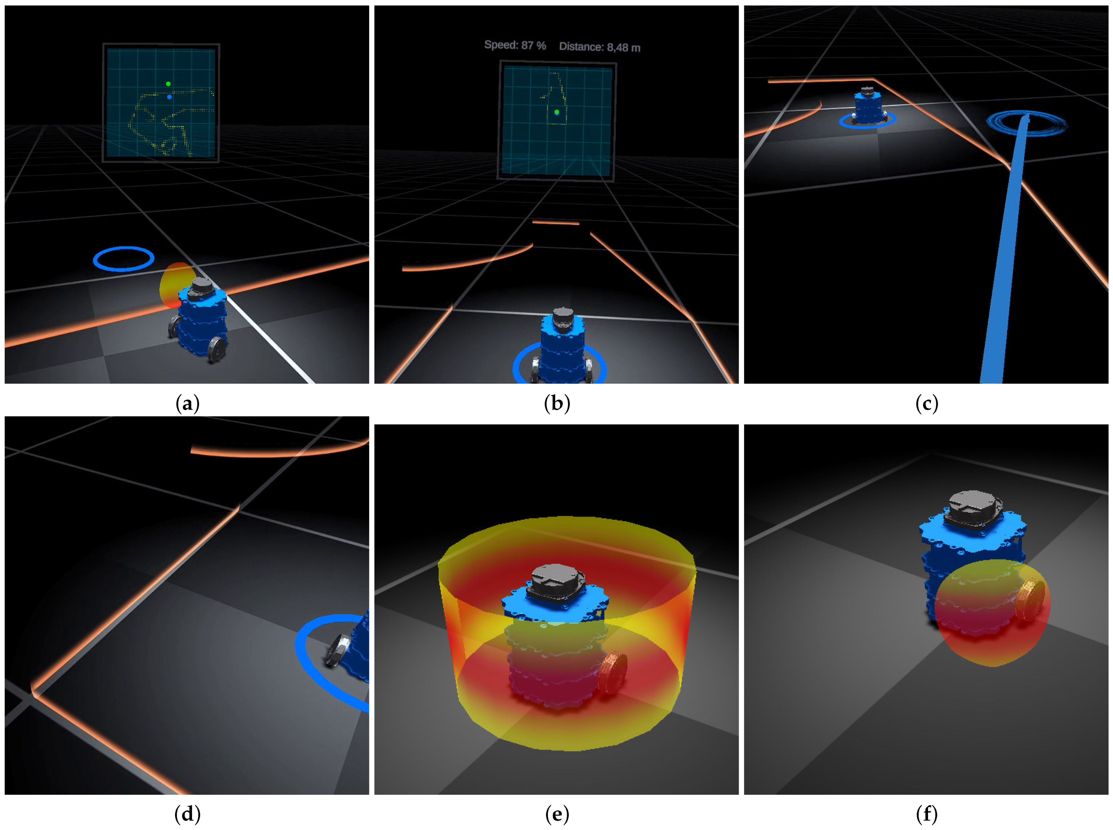
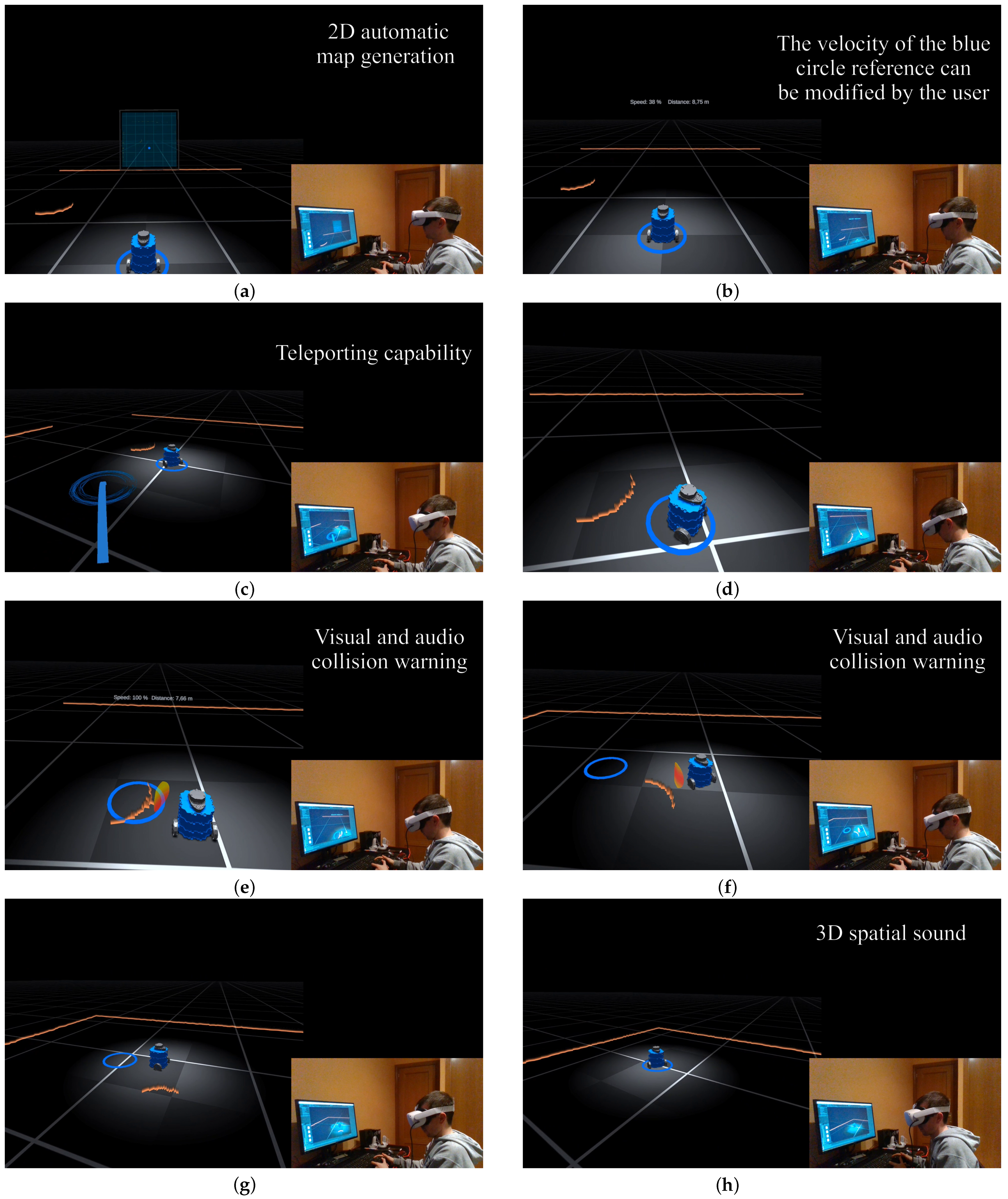
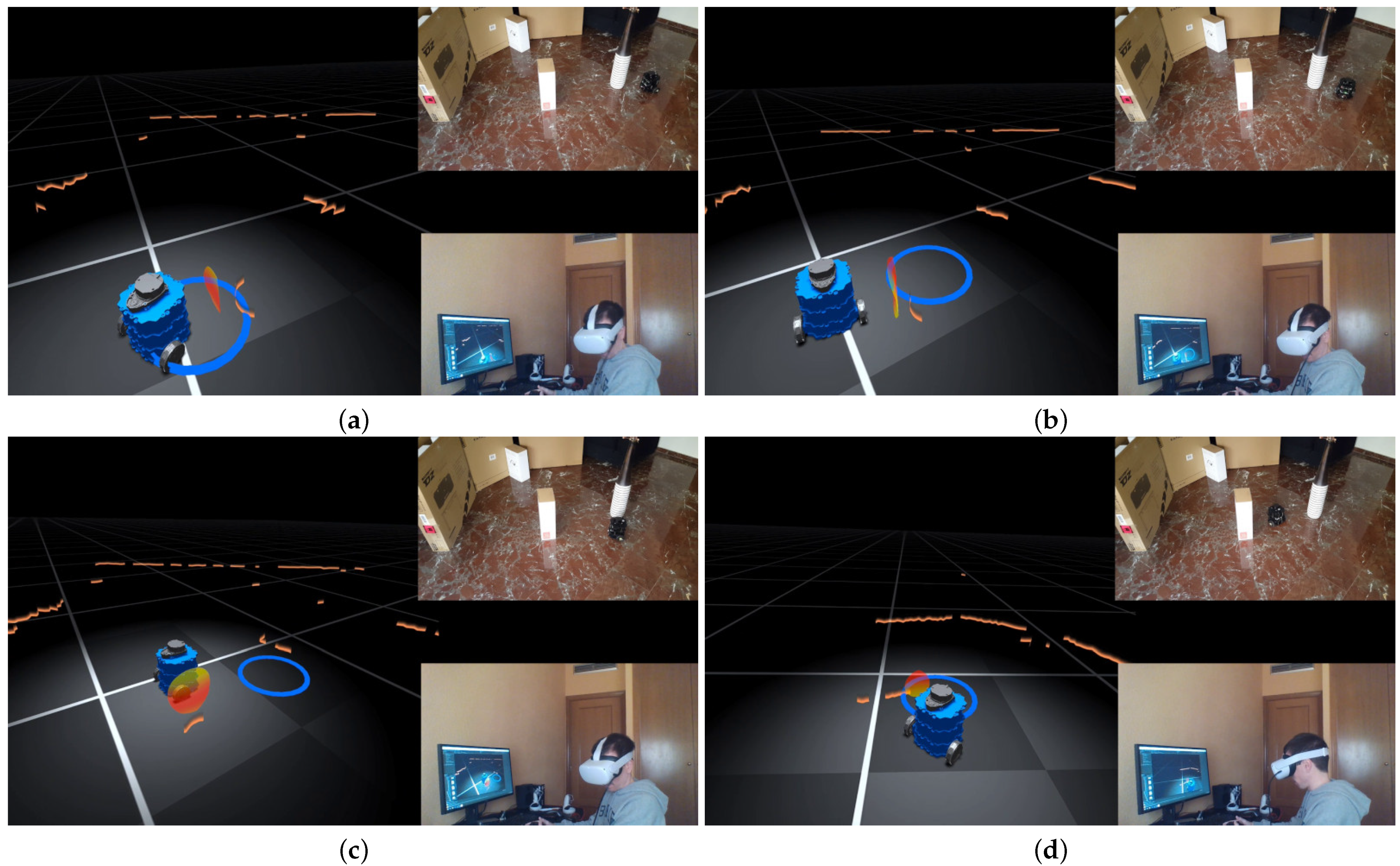
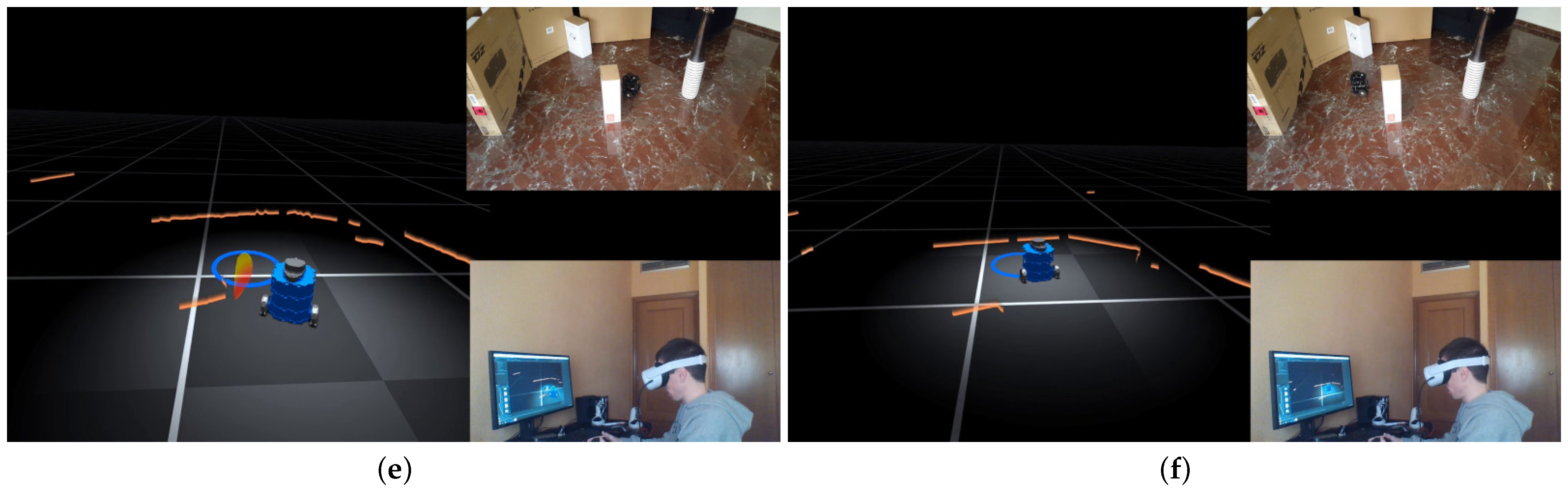
  • Teleporting: the user can “jump” from their current position to another position in the environment using the gamepad. Figure 2c shows the designed teleporting element, which consists of an animated blue arrowed circle. This element is designed according to the standard representation of teleporting in most current VR applications. Note that, when the teleporting option is activated, the user cannot simultaneously move the reference position of the robot for security reasons.
Finally, two types of sounds are developed to increase the feeling of reality in the VE:
  • The movement of the robot produces a characteristic sound due to the robot servos, whose treble variation depends on the speed of the robot. To give it more realism, this sound is recorded directly from the actual sound of the robot moving at low speeds. The treble change of this base sound is carried out proportionally to the speed of the wheels, producing a real sensation of movement of the robot in the VE. This sound effect cannot be disabled by the user. In addition, this is a 3D sound that changes depending on the distance from the user to the robot position, providing the user with a more realistic level of immersion in the task.
  • An alarm sound is also included to warn the user of collisions between the robot boundary and the obstacles in its environment. As in the previous case, this is also a 3D sound. However, contrary to the later, the user is allowed to deactivate this warning sound, since the nature of the proposed assisted teleoperation approach can lead to situations where the user, for instance, takes the robot to areas where collisions occur, or takes the robot to very tight zones where collisions cannot be avoided. In either case, the user’s attention would be on the robot, so the visual effect of the boundary alone would suffice. Note also that this warning sound for long periods could become annoying.

2.3. High Level Controller: Mobile Robot Navigation with the Potential Field-Based Method

The well-known conventional potential field-based method [59] is typically used for mobile robot navigation with collision avoidance. In particular, this approach consists of using virtual forces, i.e., attractive and repulsive forces, to determine the robot movement, as detailed below.
The commonly used attractive and repulsive forces have the following form [60]:
F a t t = K a t t p r e f p
F r e p = K r e p ρ 1 ρ 0 1 ρ 2 ρ if ρ < ρ 0 0 otherwise ,
where vector F a t t is the attractive force to the reference; vector F r e p is the repulsive force from the obstacles; the positive constants K a t t and K r e p represent the gains of the attractive and repulsive forces, respectively; vectors p r e f and p are the reference position and the actual robot position, respectively; ρ is the minimum distance from the obstacles to the mobile robot boundary; vector ρ represents the gradient of the mentioned minimum distance, i.e., a vector pointing from the closest obstacle to the mobile robot boundary; and ρ 0 is a positive constant denoting the distance of influence of the obstacles for the repulsive force.
Thus, the sum of all “forces” determines the magnitude and direction of the robot motion as follows:
p ˙ t , c = F a t t + F r e p ,
where vector p ˙ t , c represents the commanded value for the velocity of the robot tracking point, i.e., the point of the mobile robot that tracks the reference signal.
Next, the specific mobile robot used in this work for the experimentation is taken into account to compute the minimum distance ρ between the detected obstacles and the mobile robot boundary, as well as the commands for the robot wheel velocities.
As mentioned before, due to the shape of the Turtlebot3 Burger, the 2D boundary for the mobile robot is simple modeled in this work as a circle (Without loss of generality, other 2D boundaries could also be considered for other specific mobile robots, e.g., a square or an ellipse, details omitted for brevity). Therefore, the minimum distance ρ between the detected obstacles and the mobile robot boundary is given by
ρ i = R 2 P x , i 2 + P y , i 2 R 2 ρ = min { ρ i } ,
where R is the radius of the circle used to model the mobile robot boundary, P i = [ P x , i P y , i ] T is the 2D position of the i-th detected point of the obstacles relative to the center of the boundary circle, and ρ i is the normalized distance from point P i to the boundary circle. Note that this normalized distance has no units.
Since the Turtlebot3 Burger is a differential-drive mobile robot [61], the tracking point considered in this work is located on the longitudinal symmetry axis of the mobile robot and at a distance M from the rotation axle of the fixed wheels [62]. Hence, the commanded value for the mobile robot motion is given by [63]
v c ω c = cos ( θ ) sin ( θ ) sin ( θ ) / M cos ( θ ) / M p ˙ t , c
φ ˙ r , c φ ˙ l , c = r 1 1 L / 2 1 L / 2 v c ω c ,
where θ is the orientation angle of the mobile robot relative to the X-axis; r is the radius of the fixed wheels of the robot; L is the distance between the robot wheels; v c and ω c are the commanded value for the forward and angular velocities, respectively, of the mobile robot; and φ ˙ r , c and φ ˙ l , c are the commanded value for the angular velocity of the right and left wheels, respectively.

3. Results

With respect to the remote workspace hardware, Figure 3 shows the two different platforms that were used to demonstrate the suitability and effectiveness of the proposed approach. Figure 3a shows the simulator setup using Gazebo [64,65], whilst Figure 3b shows the real platform. In both cases, the robot used was the Turtlebot3 Burger, a differential-drive mobile robot equipped with two servos Dynamixel XL430-W250-T for the wheels, an OpenCR (32-bit ARM Cortex-M7) embedded controller (Robot controller), a RaspBerry Pi-3 (High-level controller), and an LDS, see [56] for further details. Obstacles with different shapes such as cylinders, ellipsoids (rounded corners) or boxes (sharp corners) were used in both platforms. Remark that the correct measurement of the distance from the mobile robot to the obstacles in the environment directly depends on the sensors used and the typology of the obstacle to be detected. In this work, an LDS sensor is sufficient to properly detect the obstacles used in the real experimentation. However, for objects with different characteristics (e.g., reflective materials and irregular shapes) other appropriate sensors (e.g., vision system, infrared sensors and ultrasonic sensors) could be required to obtain a proper obstacle detection so that these sensors could complement or replace the one used in this work.
With respect to the local workspace hardware, the Oculus Quest 2 VR headset [53] and the Xbox Wireless Controller (gamepad) [55] were used.
The communication protocol between the robot high-level controller and the VR headset was via Wi-Fi Ethernet TCP/UDP. The LSD data were updated at 1 Hz, and the robot pose (i.e., position and orientation) and user commands were updated at 20 Hz. The communication protocol between the VR headset and the Xbox wireless controller was via Bluetooth.
The parameter values used for the high level controller of the robot are as follows: potential field-based method { ρ 0 = 0.35 , K a t t = 0.75 , K r e p = 1 } ; robot kinematics { L = 0.16 m , M = 0.052 m , r = 0.033 m } ; and boundary circle with radius R = 0.18 m and center located at the mobile robot tracking point.

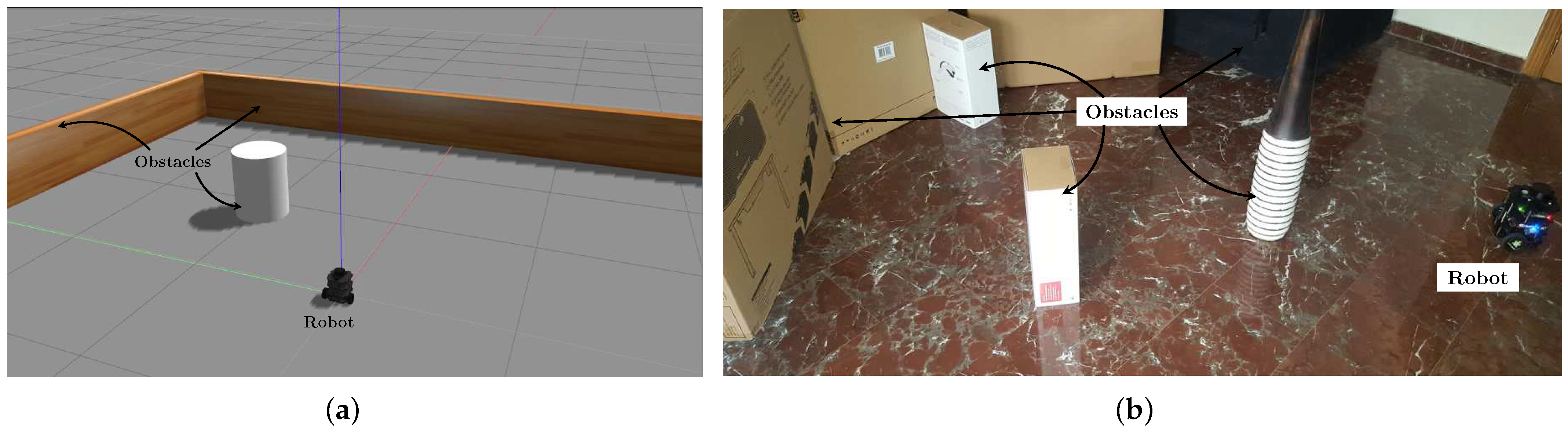
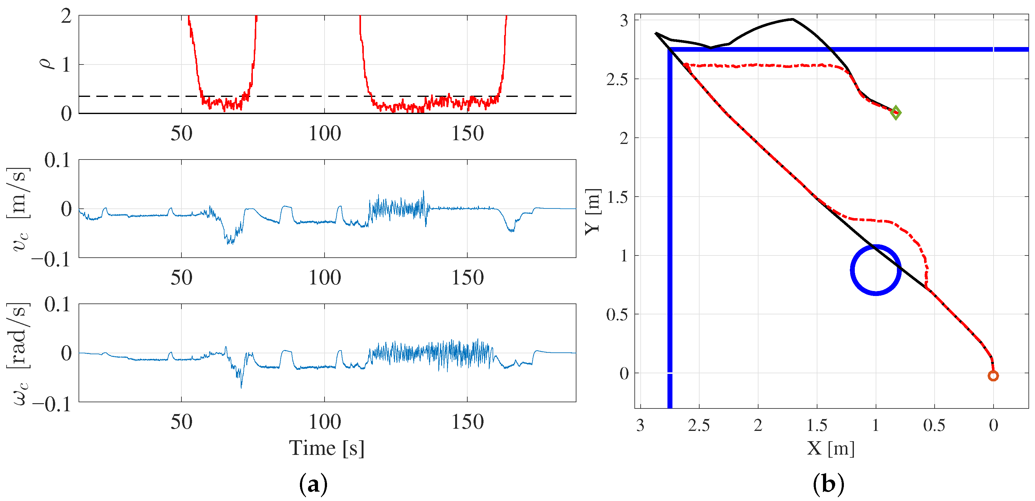
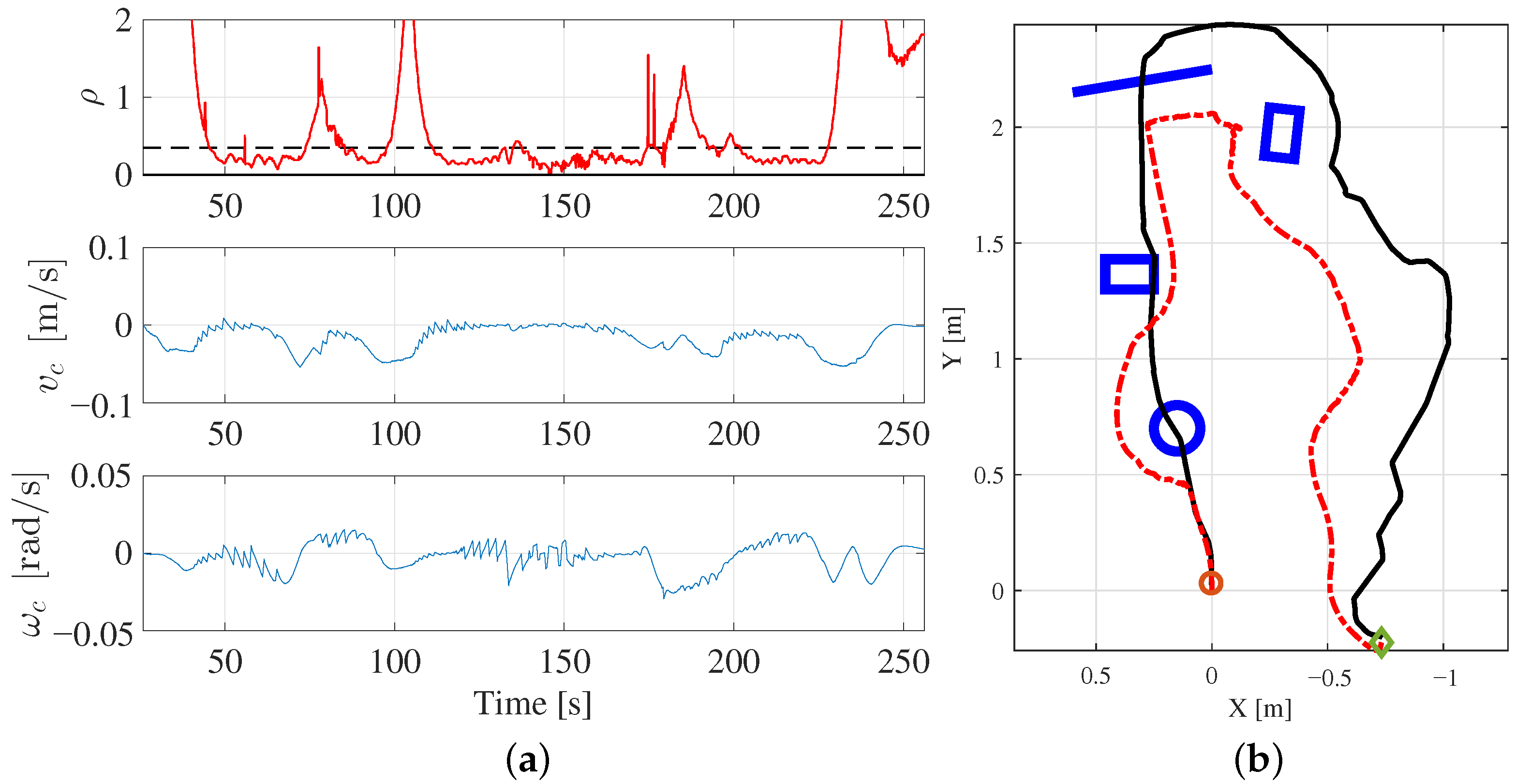
3.1. Case Study 1: Virtual Application Functionalities and Behavior

A first experiment was conducted to show the proposed VE and its functionalities, which can be played in [66]. In this case, the Turtlebot3 Burger model using the Gazebo simulator was used, and the environment consisted of a cylinder obstacle and four rectangles defining the allowed square region; see Figure 3a. In particular, Figure 4 shows several frames of this experiment, whilst Figure 5 shows the trajectory and control performance of the overall experiment. The user can activate the 2D map option to see an orthogonal representation of the environment with the “discovered objects”, and the location of the robot and the reference; see Figure 4a. The user is able to activate the task information data, e.g., robot velocity or target distance, at any moment; see Figure 4b. Note that these data depend on the application, and it would be easy to add the required information into the panel. Figure 4c shows the teleporting functionality. We remark that when this option is activated, the user cannot move the robot reference for security reasons. The obstacle avoidance capability can be seen from Figure 4c–f. Note that even though the user guides the reference through the cylinder obstacle, the robot successfully avoids this obstacle and reaches the reference when possible. This behavior can be better seen in Figure 5a,b. The repulsive force of the potential field-based navigation method becomes active around time instant 57 s when the distance ρ between the detected obstacles and the mobile robot boundary becomes lower than threshold ρ 0 , see Figure 5a and Equation (2), causing the robot deviation from the trajectory marked by the reference (see Figure 5b). Note also that when the mentioned repulsive force is deactivated, i.e., when the distance ρ between the detected obstacles and the mobile robot boundary becomes larger than threshold ρ 0 (see Equation (2)), the robot returns to the path of the reference. Note that a so-called “trap situation” arises around time instant 115 s, i.e., the forward and angular velocities of the mobile robot are approximately zero; see Figure 5a. This is due to the fact that the robot has reached a corner; see position X = Y = 2.5 m in Figure 5b. Remark that these trap situations are typically present in potential field-based control schemes, and could be overcome if the user “helps” the robot in guiding the reference to an area reachable by the robot.
In the video recording, the 3D sound effect can also be appreciate, i.e., both servo sounds and warning sounds are local to the robot, and the user perceives these sounds differently depending on the distance between the robot and the user.

3.2. Case Study 2: Real Robot Behavior

A second experiment was conducted to demonstrate the feasibility and suitability of the proposed virtual reality interface to control a real mobile robot. Figure 3b shows the remote environment used for this case study, which includes several obstacles located strategically to cause challenging situations, such as the avoidance of obstacles with round and sharp corners and trap situations. The video of this experiment can be played in [67].
For this second experiment, Figure 6 shows the normalized distance ρ between the detected obstacles and the mobile robot boundary together with the control velocity commands.
Moreover, Figure 7 shows several frames of this experiment related to the obstacle avoidance capability of the robot and how this is depicted in the VE. In particular, Figure 7a,c show the robot performance when avoiding an obstacle with rounded shape; see the time interval 45–74 s in the graphs of Figure 6a. Note that the robot deviates from the reference trajectory when the repulsive force of the potential field-based navigation method becomes active (i.e., ρ < ρ 0 ) (see the top graph in Figure 6a), and tries to go back to the reference once the mentioned repulsive force is deactivated, i.e., when ρ > ρ 0 . In addition, Figure 7d–f show the robot performance when avoiding an obstacle with sharp corners; see time interval 85–97 s in the graphs of Figure 6a. As in the previous case, the activation of the repulsive force during this time span allows the mobile robot to successfully avoid this kind of obstacle (Figure 6b).
In addition, Figure 8 depicts several frames of this experiment to show how the robot deals with a trap situation, which occurs around time interval 137–175 s, see Figure 6a. As commented above, this behavior is typically present in potential field-based approaches and, in this case, the user successfully assists the robot to escape from this trap situation by guiding the reference trajectory to an area reachable by the robot.

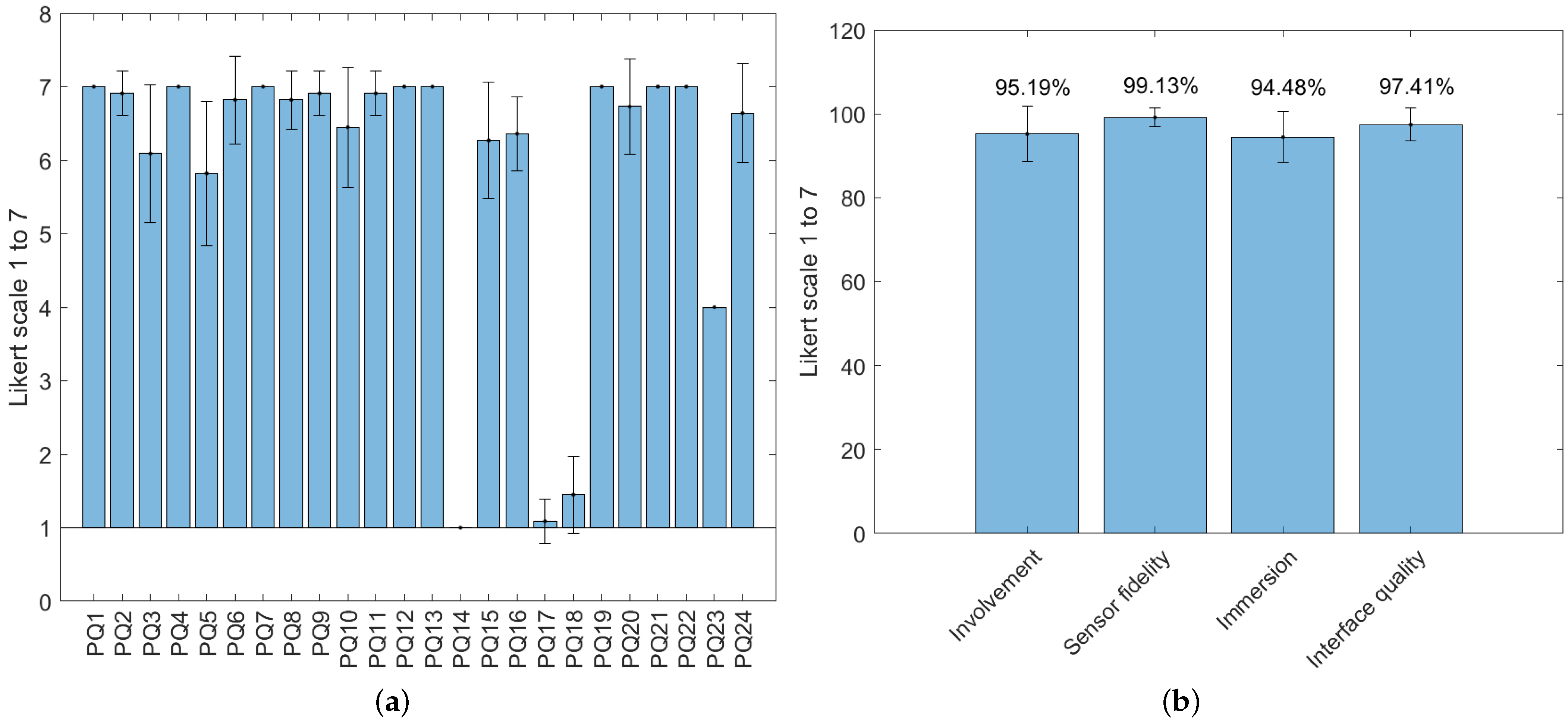
3.3. Usability Analysis Results

Similar to [68,69,70], several methods, such as the usability tests of applications, which are traditionally used to validate hardware and software, together with users’ interviews, were conducted to show the advantages of the proposed approach.
Remark that most of the works proposing a new virtual reality interface for robot applications show its performance for just one user. However, there are few researchers that conduct some kind of usability test to prove its performance with several participants. For instance, in [7], a virtual reality application for the teleoperation of military mobile robotic systems was presented, and 15 participants were considered to prove its performance. In [71], 10 participants were considered to validate a human–robot collaborative control in a virtual reality-based telepresence system. Finally, in [9], 11 participants were used to validate the mixed reality interface developed for robot teleoperation.
Note that the mentioned works considered a similar number of participants, ranging from 10 to 15 participants, and with an average value of 12. Therefore, 11 participants were selected in this work for the usability and presence questionnaires.
It is important to remark that considering a specific sample size gives rise to a certain margin of error [72]. In particular, for a sample of 11 participants and considering a confidence level of 95% and unlimited population size, the margin error is only 29.55%, which means that there is a 95% chance that the real value is within ±29.55% of the value obtained with the selected sample, which is fairly reasonable.
Furthermore, in order to have a representative sample, the 11 participants selected for the comparison experiment had different backgrounds. The main information about these participants is the following: 54.55% of the participants were female, whilst the remaining 45.45% were male; it was pretended to cover the maximum age range such that 18.18% of the participants were under 18 years old, 18.18% of them were between 18 and 40 years old, 18.18% of them were between 40 and 55 years old, 27.27% of them were between 55 and 70 years old, and 18.18% of the participants were older than 70 years old. With respect to their level of studies, 72.73% of the participants indicated basics studies, 18.18% of them indicated bachelor studies, and 9.09% of the participants indicated post-grade studies. In addition, 81.82% of the participants indicated that they had never used virtual reality headsets, whilst the remaining 18.18% of them indicated to have some experience with virtual reality applications and devices. Moreover, 63.64% of the participants indicated not having experience with video games and/or gamepad devices, whilst 36.36% of the participants indicated being video game players.
The procedure followed to conduct the tests was as follows. Firstly, a brief description of the virtual reality devices and robotic applications was given to each participant. Note that the task to be performed was to guide the mobile robot to a certain location to perform a rescue operation in the shortest possible time in an unknown environment. Hence, in second place, training was performed by each participant to become used to the VE and the control device (i.e., gamepad controls). In this case, the same scenario shown in Section 3.1 (see Figure 3a) with the Gazebo-based robot model was used. The training took around 15 min per participant.
After the training, the participant performed the required “rescue operation”. In this case, a complete different scenario was used (see Figure 9) which was modeled using Blender 2.93 [73]. A demonstrative video can be played in [74]. All participants successfully performed the task, and the average time to complete it was 5 min 7 s, with a standard deviation of 17 s.
After the test, the participants were asked to complete three standard questionnaires: the presence questionnaire (PQ) [75,76], the Igroup Presence Questionnaire (IPQ) [77,78,79], and the system usability scale (SUS) [80]. The PQ and IPQ questionnaires were chosen because they are widely used to evaluate the sense of presence in VEs, the realism, the interface and chosen devices quality, among other factors. The SUS questionnaire was used to test the usability of the proposed interface because it is short, concise and widely used.
The PQ was conducted in order to evaluate the user experience in the VE [75]. Twenty four of the twenty nine total questions of the third version of the PQ questionnaire were selected according to the nature of the proposed application; see Table 1. The PQ uses a seven-point Likert-type scale and has four subscales: involvement, sensor fidelity, immersion and interface quality.
Figure 10 shows the results of the PQ. Concretely, Figure 10a shows the mean and standard deviation for each question of the PQ, whilst Figure 10b shows the mean, standard deviation and total percentage for each PQ subscale. In particular, the Involvement score was 95.19% with a standard deviation of 6.61, which means that the users paid close attention to the virtual reality environment and actively participated in all aspects present. The sensor fidelity score was 99.13% with a standard deviation of 2.26, which means that the users could observe from multiple views and interact with all objects present in the VE easily and without problems. The immersion score was 94.48% with a standard deviation of 6.05, which means that users could adapt themselves quickly and easily to the VE, and could perform the task without distractions. Finally, the interface quality score was 97.40% with a standard deviation of 3.92, which means that users did not perceive failures or malfunctions in the virtual reality interface during the tasks.
On the other hand, the IPQ was conducted in order to measure the sense of presence experienced by users in the proposed VE [77]. The IPQ is composed of 14 questions used to evaluate three subscales: spatial presence, i.e., the sense of being physically present in the VE; involvement, i.e., measuring the attention devoted to the VE and the involvement experience; and experienced realism, i.e., measuring the subjective experience of realism in the VE. In addition to this, the IPQ has an additional general item that assesses the general “sense of being there”, and has high loadings on all three factors, especially on spatial presence. The IPQ questions are shown in Table 2.
Figure 11 shows the results of the IPQ. Concretely, Figure 11a shows the mean, and standard deviation for each question of the IPQ, whilst Figure 11b shows the mean, standard deviation and total percentage for each PQ subscale. In particular, the general presence score was 94.81% with a standard deviation of 6.87, which indicates that users felt like they were inside the VE. The spacial presence score was 99.74% with a standard deviation of 0.58, which means that users felt like they were physically present in the VE. The involvement score was 92.86% with a standard deviation of 9.51, which is very similar to that of the PQ, corroborating that users actively participated and focused on all aspects of the VE. Finally, the experienced realism score was 35.71% with a standard deviation of 42.86, which means that users felt in any moment that they were in a VE, with no realistic objects present in there. This coincides with the goal of the proposed approach, which was not to design a “realistic” scenario but a natural and user-friendly VE to be used in most of the current commercial VR headsets. Note that increasing realism implies more computational cost and the use of specialized hardware, i.e., graphic cards.
Regarding the SUS questionnaire, the overall perceived usability was 90.91 out of 100 (min 77.5; max 100; SD 7.18), which means that the proposed VR-based interface reached a high level of usability. In addition, Figure 12 shows the results obtained for each question of the SUS questionnaire, which are detailed in Table 3. Note that most of the participants would use this interface frequently and found the interface easy to use. The participants also indicated that all the interface functionalities were well integrated and that the proposed interface was consistent. Moreover, the participants felt confident with the interface.

4. Conclusions

A virtual reality-based interface for advanced assisted teleoperation of mobile robots was developed in this work to assist human operators to conduct operations, such as human rescue, bomb deactivation, etc. For this purpose, virtual reality and sensor feedback were used to provide the user an immersive virtual experience when remotely teleoperating the robot system in order to properly perform the task.
The main advantages of the proposal are twofold. Firstly, the proposed virtual environment is useful to provide a more natural manner to teleoperate these kind of robots, which improves the task performance. Secondly, the synergistic effect between the human, who provides flexibility to adapt to complex situations, and the robot, which is able to automatically avoid the obstacles in its environment, makes the proposed approach user friendly and allows the robot to deal with challenging situations, e.g., to escape from trap situations.
Furthermore, the feasibility and effectiveness of the proposed virtual reality interface for advanced assisted teleoperation of mobile robots were shown through experimental results, using a differential-drive mobile robot, the Turtlebot3 Burger, equipped with a 360° LiDAR sensor. Although in this work, only the robot odometry and LiDAR sensor were used, the information provided from other sensors, such as vision systems, could be easily added in order to include in the local environment (virtual world) more information from the remote environment (real world).
In addition, several usability and presence questionnaires were carried out with users of different ages and backgrounds. The results showed that the proposed virtual reality based interface is intuitive, ergonomic and easy to use.
This work assumed that the robot goes through a totally unknown environment. If there is previous knowledge of the environment, one possibility would be to improve the teleporting option by showing the “allowed” areas in a blue circle (such as the one shown in this work) and the “not allowed” areas with a red circle, thus constraining the user movements within the virtual world.
Moreover, if the environment is totally or partially known, it would be interesting to introduce a trajectory planner, which in combination with the manual teleoperation carried out by the human, would lead to a semi-automatic teleoperation mode. In this mode, the planner would indicate the optimal trajectory to the human operator, who would be free to follow it or not depending on the situation.
In this work, the well-known potential field-based navigation method was used for the high-level controller of the mobile robot. However, other controllers could be considered to improve the performance of the mobile robot navigation in different ways, e.g., sliding mode control approaches [81] or intelligent model-free control approaches [82] could be used.

Author Contributions

Conceptualization, J.E.S. and A.M.; Funding acquisition, L.G. and J.T.; Investigation, J.E.S., A.M. and L.G.; Methodology, J.E.S.; Resources, L.G. and J.T.; Software, A.M.; Supervision, L.G. and J.T.; Validation, J.E.S.; Writing—original draft, J.E.S.; Writing—review & editing, L.G. All authors have read and agreed to the published version of the manuscript.

Funding

This research was funded by the Spanish Government (Grant PID2020-117421RB-C21 funded by MCIN/AEI/10.13039/501100011033) and by the Generalitat Valenciana (Grant GV/2021/181).

Conflicts of Interest

The authors declare no conflict of interest.

References

  1. Saputra, R.P.; Rakicevic, N.; Kuder, I.; Bilsdorfer, J.; Gough, A.; Dakin, A.; de Cocker, E.; Rock, S.; Harpin, R.; Kormushev, P. ResQbot 2.0: An Improved Design of a Mobile Rescue Robot with an Inflatable Neck Securing Device for Safe Casualty Extraction. Appl. Sci. 2021, 11, 5414. [Google Scholar] [CrossRef]
  2. Habibian, S.; Dadvar, M.; Peykari, B.; Hosseini, A.; Salehzadeh, M.H.; Hosseini, A.H.M.; Najafi, F. Design and implementation of a maxi-sized mobile robot (Karo) for rescue missions. ROBOMECH J. 2021, 8, 1. [Google Scholar] [CrossRef]
  3. Sun, Z.; Yang, H.; Ma, Y.; Wang, X.; Mo, Y.; Li, H.; Jiang, Z. BIT-DMR: A Humanoid Dual-Arm Mobile Robot for Complex Rescue Operations. IEEE Robot. Autom. Lett. 2022, 7, 802–809. [Google Scholar] [CrossRef]
  4. Schuster, M.J.; Müller, M.G.; Brunner, S.G.; Lehner, H.; Lehner, P.; Sakagami, R.; Dömel, A.; Meyer, L.; Vodermayer, B.; Giubilato, R.; et al. The ARCHES Space-Analogue Demonstration Mission: Towards Heterogeneous Teams of Autonomous Robots for Collaborative Scientific Sampling in Planetary Exploration. IEEE Robot. Autom. Lett. 2020, 5, 5315–5322. [Google Scholar] [CrossRef]
  5. Jia, X.; Sun, C.; Fu, J. Mobile Augmented Reality Centred Ietm System for Shipping Applications. Int. J. Robot. Autom. 2022, 37, 147–162. [Google Scholar] [CrossRef]
  6. Yin, K.; Sun, Q.; Gao, F.; Zhou, S. Lunar surface soft-landing analysis of a novel six-legged mobile lander with repetitive landing capacity. Proc. Inst. Mech. Eng. Part C J. Mech. Eng. Sci. 2022, 236, 1214–1233. [Google Scholar] [CrossRef]
  7. Kot, T.; Novák, P. Application of virtual reality in teleoperation of the military mobile robotic system TAROS. Int. J. Adv. Robot. Syst. 2018, 15, 1–6. [Google Scholar] [CrossRef] [Green Version]
  8. Kavitha, S.; SadishKumar, S.T.; Menaga, T.; Gomathi, E.; Sanjay, M.; Abarna, V.S. Military Based Voice Controlled Spy Bot with Weapon Detector. Biosci. Biotechnol. Res. Commun. 2020, 13, 142–146. [Google Scholar]
  9. Grabowski, A.; Jankowski, J.; Wodzyński, M. Teleoperated mobile robot with two arms: The influence of a human-machine interface, VR training and operator age. Int. J. Hum.-Comput. Stud. 2021, 156, 102707. [Google Scholar] [CrossRef]
  10. Li, C.; Li, B.; Wang, R.; Zhang, X. A survey on visual servoing for wheeled mobile robots. Int. J. Intell. Robot. Appl. 2021, 5, 203–218. [Google Scholar] [CrossRef]
  11. Szrek, J.; Jakubiak, J.; Zimroz, R. A Mobile Robot-Based System for Automatic Inspection of Belt Conveyors in Mining Industry. Energies 2022, 15, 327. [Google Scholar] [CrossRef]
  12. Khalaji, A.K.; Zahedifar, R. Lyapunov-Based Formation Control of Underwater Robots. Robotica 2020, 38, 1105–1122. [Google Scholar] [CrossRef]
  13. Mahmud, M.S.A.; Abidin, M.S.Z.; Buyamin, S.; Emmanuel, A.A.; Hasan, H.S. Multi-objective Route Planning for Underwater Cleaning Robot in Water Reservoir Tank. J. Intell. Robot. Syst. 2021, 101, 9. [Google Scholar] [CrossRef]
  14. Doss, A.S.A.; Venkatesh, D.; Ovinis, M. Simulation and experimental studies of a mobile robot for underwater applications. Int. J. Robot. Autom. 2021, 36, 10–17. [Google Scholar] [CrossRef]
  15. Guzman Ortiz, E.; Andres, B.; Fraile, F.; Poler, R.; Ortiz Bas, A. Fleet Management System for Mobile Robots in Healthcare Environments. J. Ind. Eng. Manag.-Jiem 2021, 14, 55–71. [Google Scholar] [CrossRef]
  16. Law, M.; Ahn, H.S.; Broadbent, E.; Peri, K.; Kerse, N.; Topou, E.; Gasteiger, N.; MacDonald, B. Case studies on the usability, acceptability and functionality of autonomous mobile delivery robots in real-world healthcare settings. Intell. Serv. Robot. 2021, 14, 387–398. [Google Scholar] [CrossRef]
  17. Lim, H.; Kim, S.W.; Song, J.B.; Cha, Y. Thin Piezoelectric Mobile Robot Using Curved Tail Oscillation. IEEE Access 2021, 9, 145477–145485. [Google Scholar] [CrossRef]
  18. Cardoso, J.C.S. Comparison of Gesture, Gamepad, and Gaze-Based Locomotion for VR Worlds. In Proceedings of the 22nd ACM Conference on Virtual Reality Software and Technology, Munich, Germany, 2–4 November 2016; pp. 319–320. [Google Scholar]
  19. Kitson, A.; Hashemian, A.M.; Stepanova, E.R.; Kruijff, E.; Riecke, B.E. Comparing leaning-based motion cueing interfaces for virtual reality locomotion. In Proceedings of the 2017 IEEE Symposium on 3D User Interfaces (3DUI), Los Angeles, CA, USA, 18–19 March 2017; pp. 73–82. [Google Scholar]
  20. Zhao, J.; Allison, R.S. Comparing head gesture, hand gesture and gamepad interfaces for answering Yes/No questions in virtual environments. Virtual Real. 2019, 24, 515–524. [Google Scholar] [CrossRef]
  21. Solanes, J.E.; Muñoz, A.; Gracia, L.; Martí, A.; Girbés-Juan, V.; Tornero, J. Teleoperation of industrial robot manipulators based on augmented reality. Int. J. Adv. Manuf. Technol. 2020, 111, 1077–1097. [Google Scholar] [CrossRef]
  22. Niemeyer, G.; Preusche, C.; Stramigioli, S.; Lee, D. Telerobotics. In Springer Handbook of Robotics; Siciliano, B., Khatib, O., Eds.; Springer International Publishing: Cham, Switzerland, 2016; pp. 1085–1108. [Google Scholar]
  23. Bandala, M.; West, C.; Monk, S.; Montazeri, A.; Taylor, C.J. Vision-Based Assisted Tele-Operation of a Dual-Arm Hydraulically Actuated Robot for Pipe Cutting and Grasping in Nuclear Environments. Robotics 2019, 8, 42. [Google Scholar] [CrossRef] [Green Version]
  24. Abi-Farraj, F.; Pacchierotti, C.; Arenz, O.; Neumann, G.; Giordano, P.R. A Haptic Shared-Control Architecture for Guided Multi-Target Robotic Grasping. IEEE Trans. Haptics 2020, 13, 270–285. [Google Scholar] [CrossRef] [PubMed] [Green Version]
  25. Suarez, A.; Real, F.; Vega, V.M.; Heredia, G.; Rodriguez-Castaño, A.; Ollero, A. Compliant Bimanual Aerial Manipulation: Standard and Long Reach Configurations. IEEE Access 2020, 8, 88844–88865. [Google Scholar] [CrossRef]
  26. Isop, W.A.; Gebhardt, C.; Nägeli, T.; Fraundorfer, F.; Hilliges, O.; Schmalstieg, D. High-Level Teleoperation System for Aerial Exploration of Indoor Environments. Front. Robot. AI 2019, 6, 95. [Google Scholar] [CrossRef] [PubMed] [Green Version]
  27. Brantner, G.; Khatib, O. Controlling Ocean One: Human–robot collaboration for deep-sea manipulation. J. Field Robot. 2021, 38, 28–51. [Google Scholar] [CrossRef]
  28. Sivčev, S.; Coleman, J.; Omerdić, E.; Dooly, G.; Toal, D. Underwater manipulators: A review. Ocean Eng. 2018, 163, 431–450. [Google Scholar] [CrossRef]
  29. Chen, H.; Huang, P.; Liu, Z. Mode Switching-Based Symmetric Predictive Control Mechanism for Networked Teleoperation Space Robot System. IEEE/ASME Trans. Mechatron. 2019, 24, 2706–2717. [Google Scholar] [CrossRef]
  30. Yoon, H.; Jeong, J.H.; Yi, B. Image-Guided Dual Master–Slave Robotic System for Maxillary Sinus Surgery. IEEE Trans. Robot. 2018, 34, 1098–1111. [Google Scholar] [CrossRef]
  31. Saracino, A.; Oude-Vrielink, T.J.C.; Menciassi, A.; Sinibaldi, E.; Mylonas, G.P. Haptic Intracorporeal Palpation Using a Cable-Driven Parallel Robot: A User Study. IEEE Trans. Biomed. Eng. 2020, 67, 3452–3463. [Google Scholar] [CrossRef]
  32. Chen, Y.; Zhang, S.; Wu, Z.; Yang, B.; Luo, Q.; Xu, K. Review of surgical robotic systems for keyhole and endoscopic procedures: State of the art and perspectives. Front. Med. 2020, 14, 382–403. [Google Scholar] [CrossRef]
  33. Kapoor, A.; Li, M.; Taylor, R.H. Spatial Motion Constraints for Robot Assisted Suturing Using Virtual Fixtures. In Proceedings of the Medical Image Computing and Computer-Assisted Intervention—MICCAI 2005, Palm Springs, CA, USA, 26–29 October 2005; Duncan, J.S., Gerig, G., Eds.; Springer: Berlin/Heidelberg, Germany, 2005; pp. 89–96. [Google Scholar]
  34. Kono, H.; Mori, T.; Ji, Y.; Fujii, H.; Suzuki, T. Development of Perilous Environment Estimation System Using a Teleoperated Rescue Robot with On-board LiDAR. In Proceedings of the 2019 IEEE/SICE International Symposium on System Integration (SII), Paris, France, 14–16 January 2019; pp. 7–10. [Google Scholar]
  35. Johnson, M.; Vera, A. No AI Is an Island: The Case for Teaming Intelligence. AI Mag. 2019, 40, 16–28. [Google Scholar] [CrossRef] [Green Version]
  36. Selvaggio, M.; Abi-Farraj, F.; Pacchierotti, C.; Giordano, P.R.; Siciliano, B. Haptic-Based Shared-Control Methods for a Dual-Arm System. IEEE Robot. Autom. Lett. 2018, 3, 4249–4256. [Google Scholar] [CrossRef] [Green Version]
  37. Nicolis, D.; Palumbo, M.; Zanchettin, A.M.; Rocco, P. Occlusion-Free Visual Servoing for the Shared Autonomy Teleoperation of Dual-Arm Robots. IEEE Robot. Autom. Lett. 2018, 3, 796–803. [Google Scholar] [CrossRef]
  38. Lu, Z.; Huang, P.; Liu, Z. Predictive Approach for Sensorless Bimanual Teleoperation Under Random Time Delays With Adaptive Fuzzy Control. IEEE Trans. Ind. Electron. 2018, 65, 2439–2448. [Google Scholar] [CrossRef]
  39. Gorjup, G.; Dwivedi, A.; Elangovan, N.; Liarokapis, M. An Intuitive, Affordances Oriented Telemanipulation Framework for a Dual Robot Arm Hand System: On the Execution of Bimanual Tasks. In Proceedings of the 2019 IEEE/RSJ International Conference on Intelligent Robots and Systems (IROS), Macau, China, 3–8 November 2019; pp. 3611–3616. [Google Scholar]
  40. Clark, J.P.; Lentini, G.; Barontini, F.; Catalano, M.G.; Bianchi, M.; O’Malley, M.K. On the role of wearable haptics for force feedback in teleimpedance control for dual-arm robotic teleoperation. In Proceedings of the 2019 International Conference on Robotics and Automation (ICRA), Montreal, QC, Canada, 20–24 May 2019; pp. 5187–5193. [Google Scholar]
  41. Girbés-Juan, V.; Schettino, V.; Gracia, L.; Solanes, J.E.; Demeris, Y.; Tornero, J. Combining haptics and inertial motion capture to enhance remote control of a dual-arm robot. J. Multimodal User Interfaces 2022, 16, 219–238. [Google Scholar] [CrossRef]
  42. García, A.; Solanes, J.E.; Gracia, L.; Muñoz-Benavent, P.; Girbés-Juan, V.; Tornero, J. Bimanual robot control for surface treatment tasks. Int. J. Syst. Sci. 2022, 53, 74–107. [Google Scholar] [CrossRef]
  43. Selvaggio, M.; Ghalamzan, A.; Moccia, R.; Ficuciello, F.; Siciliano, B. Haptic-guided shared control for needle grasping optimization in minimally invasive robotic surgery. In Proceedings of the IEEE/RSJ International Conference on Intelligent Robots and Systems, Macau, China, 3–8 November 2019. [Google Scholar]
  44. Girbés-Juan, V.; Schettino, V.; Demiris, Y.; Tornero, J. Haptic and Visual Feedback Assistance for Dual-Arm Robot Teleoperation in Surface Conditioning Tasks. IEEE Trans. Haptics 2021, 14, 44–56. [Google Scholar] [CrossRef]
  45. Laghi, M.; Ajoudani, A.; Catalano, M.G.; Bicchi, A. Unifying bilateral teleoperation and tele-impedance for enhanced user experience. Int. J. Robot. Res. 2020, 39, 514–539. [Google Scholar] [CrossRef]
  46. Navarro, R.; Vega, V.; Martinez, S.; Jose Espinosa, M.; Hidalgo, D.; Benavente, B. Designing Experiences: A Virtual Reality Video Game to Enhance Immersion. In Proceedings of the 10th International Conference on Applied Human Factors and Ergonomics/AHFE International Conference on Human Factors and Wearable Technologies/AHFE International Conference on Game Design and Virtual Environments, Washington, DC, USA, 24–28 July 2019. [Google Scholar] [CrossRef]
  47. Tao, G.; Garrett, B.; Taverner, T.; Cordingley, E.; Sun, C. Immersive virtual reality health games: A narrative review of game design. J. Neuroeng. Rehabil. 2021, 18, 31. [Google Scholar] [CrossRef]
  48. Shafer, D.M. The Effects of Interaction Fidelity on Game Experience in Virtual Reality. Psychol. Pop. Media 2021, 10, 457–466. [Google Scholar] [CrossRef]
  49. Ho, J.C.F.; Ng, R. Perspective-Taking of Non-Player Characters in Prosocial Virtual Reality Games: Effects on Closeness, Empathy, and Game Immersion. Behav. Inf. Technol. 2020, 41, 1185–1198. [Google Scholar] [CrossRef]
  50. Wang, J.; Yuan, X.Q. Route Planning of Teleoperation Mobile Robot based on the Virtual Reality Technology. J. Robotics Netw. Artif. Life 2020, 7, 125–128. [Google Scholar] [CrossRef]
  51. Urrea, C.; Matteoda, R. Development of a virtual reality simulator for a strategy for coordinating cooperative manipulator robots using cloud computing. Robot. Auton. Syst. 2020, 126, 103447. [Google Scholar] [CrossRef]
  52. Kuo, C.Y.; Huang, C.C.; Tsai, C.H.; Shi, Y.S.; Smith, S. Development of an immersive SLAM-based VR system for teleoperation of a mobile manipulator in an unknown environment. Comput. Ind. 2021, 132, 103502. [Google Scholar] [CrossRef]
  53. Meta, Facebook Reality Labs (Redmond, DC, USA). Oculus Quest 2 Hardware Details. Available online: https://www.oculus.com/quest-2/ (accessed on 4 March 2022).
  54. Unity (San Francisco, CA, USA). Unity Real-Time Development Platform. Available online: https://unity.com/ (accessed on 5 May 2022).
  55. Microsoft (Redmond, DC, USA). Xbox Wireless Controller Hardware Details. Available online: https://www.xbox.com/en-US/accessories/controllers/xbox-wireless-controller (accessed on 4 March 2022).
  56. Robotis (Lake Forest, CA, USA). Turtlebot3 Hardware Details. Available online: https://www.robotis.us/turtlebot-3/ (accessed on 4 March 2022).
  57. Unity (San Francisco, CA, USA). Shaders Core Concepts. Available online: https://docs.unity3d.com/Manual/Shaders.html (accessed on 4 March 2022).
  58. Virtuix (Austin, TX, USA). OmniOne Hardware Details. Available online: https://omni.virtuix.com/ (accessed on 4 March 2022).
  59. Latombe, J.C. Robot Motion Planning; Kluwer: Boston, MA, USA, 1991. [Google Scholar]
  60. Khatib, O. Real-time obstacle avoidance for manipulators and mobile robots. Int. J. Robot. Res. 1986, 5, 90–98. [Google Scholar] [CrossRef]
  61. Gracia, L.; Tornero, J. Kinematic models and isotropy analysis of wheeled mobile robots. Robotica 2008, 26, 587–599. [Google Scholar] [CrossRef]
  62. Gracia, L.; Tornero, J. Characterization of zero tracking error references in the kinematic control of wheeled mobile robots. Robot. Auton. Syst. 2009, 57, 565–577. [Google Scholar] [CrossRef]
  63. Gracia, L.; Tornero, J. Kinematic control system for car-like vehicles. In Proceedings of the Ibero-American Conference on Artificial Intelligence, Seville, Spain, 12–15 November 2002; Springer: Berlin/Heidelberg, Germany, 2002; pp. 882–892. [Google Scholar]
  64. Koenig, N.; Howard, A. Design and Use Paradigms for Gazebo, An Open-Source Multi-Robot Simulator. In Proceedings of the IEEE/RSJ International Conference on Intelligent Robots and Systems, Sendai, Japan, 28 September–2 October 2004; pp. 2149–2154. [Google Scholar]
  65. Aguero, C.; Koenig, N.; Chen, I.; Boyer, H.; Peters, S.; Hsu, J.; Gerkey, B.; Paepcke, S.; Rivero, J.; Manzo, J.; et al. Inside the Virtual Robotics Challenge: Simulating Real-Time Robotic Disaster Response. IEEE Trans. Autom. Sci. Eng. 2015, 12, 494–506. [Google Scholar] [CrossRef]
  66. Video of Experiment 1. 2022. Available online: https://media.upv.es/player/?id=7fac10d0-8ccd-11ec-ad20-231602f2b702 (accessed on 12 June 2022).
  67. Video of Experiment 2. 2022. Available online: https://media.upv.es/player/?id=31aac3c0-8cca-11ec-a6b9-39f61182889c (accessed on 12 June 2022).
  68. Blattgerste, J.; Strenge, B.; Renner, P.; Pfeiffer, T.; Essig, K. Comparing Conventional and Augmented Reality Instructions for Manual Assembly Tasks. In Proceedings of the 10th International Conference on PErvasive Technologies Related to Assistive Environments, Island of Rhodes, Greece, 21–23 June 2017; pp. 75–82. [Google Scholar] [CrossRef]
  69. Attig, C.; Wessel, D.; Franke, T. Assessing Personality Differences in Human-Technology Interaction: An Overview of Key Self-report Scales to Predict Successful Interaction. In Proceedings of the HCI International 2017—Posters’ Extended Abstracts, Vancouver, BC, Canada, 9–14 July 2017; Stephanidis, C., Ed.; Springer International Publishing: Cham, Switzerland, 2017; pp. 19–29. [Google Scholar]
  70. Franke, T.; Attig, C.; Wessel, D. A Personal Resource for Technology Interaction: Development and Validation of the Affinity for Technology Interaction (ATI) Scale. Int. J. -Hum.-Comput. Interact. 2018, 35, 456–467. [Google Scholar] [CrossRef]
  71. Du, J.; Do, H.M.; Sheng, W. Human-Robot Collaborative Control in a Virtual-Reality-Based Telepresence System. Int. J. Soc. Robot. 2021, 13, 1295–1306. [Google Scholar] [CrossRef]
  72. Uboe, J. Introductory Statistics for Business and Economics: Theory, Exercises and Solutions; Springer International Publishing AG: Cham, Switzerland, 2017; ISBN 9783319709369. [Google Scholar]
  73. Hess, R. Blender Foundations: The Essential Guide to Learning Blender 2.6; Focal Press: Waltham, MA, USA, 2010; Available online: https://www.sciencedirect.com/book/9780240814308/blender-foundations (accessed on 12 June 2022).
  74. Video of Experiment 3. 2022. Available online: https://media.upv.es/player/?id=f45e38d0-8cce-11ec-ad20-231602f2b702 (accessed on 12 June 2022).
  75. Witmer, B.G.; Singer, M.J. Measuring Presence in Virtual Environments: A Presence Questionnaire. Presence Teleoperators Virtual Environ. 1998, 7, 225–240. [Google Scholar] [CrossRef]
  76. Witmer, B.G.; Jerome, C.J.; Singer, M.J. The Factor Structure of the Presence Questionnaire. Presence Teleoperators Virtual Environ. 2005, 14, 298–312. [Google Scholar] [CrossRef]
  77. Schubert, T.; Friedmann, F.; Regenbrecht, H. The Experience of Presence: Factor Analytic Insights. Presence Teleoperators Virtual Environ. 2001, 10, 266–281. [Google Scholar] [CrossRef]
  78. Regenbrecht, H.; Schubert, T. Real and Illusory Interactions Enhance Presence in Virtual Environments. Presence Teleoperators Virtual Environ. 2002, 11, 425–434. [Google Scholar] [CrossRef]
  79. Schubert, T. The sense of presence in virtual environments: A three-component scale measuring spatial presence, involvement, and realness. Z. für Medien. 2003, 15, 69–71. [Google Scholar] [CrossRef]
  80. Brooke, J. “SUS-A Quick and Dirty Usability Scale.” Usability Evaluation in Industry; CRC Press: Boca Raton, FL, USA, 1996; ISBN 9780748404605. [Google Scholar]
  81. Gracia, L.; Garelli, F.; Sala, A. Reactive Sliding-Mode Algorithm for Collision Avoidance in Robotic Systems. IEEE Trans. Control. Syst. Technol. 2013, 21, 2391–2399. [Google Scholar] [CrossRef] [Green Version]
  82. Tutsoy, O.; Barkana, D.E.; Balikci, K. A Novel Exploration-Exploitation-Based Adaptive Law for Intelligent Model-Free Control Approaches. IEEE Trans. Cybern. 2021; 1–9, in press. [Google Scholar] [CrossRef]
Figure 1. Remote human–robot interaction using VR with data from LDS sensor and the robot odometry.
Applsci 12 06071 g001
Figure 2. VE overview. (a) The 2D map view and 3D view. (b) Requested information data. (c) Teleporting (blue arrowed circle). (d) Detected objects (elements in brown). (e) Mobile robot boundary (full view). (f) Mobile robot boundary (local view). 2D map: robot (blue circumference in (a)); reference (green circumference in (a)); detected objects (yellow points in (a,b)). 3D environment: reference (blue circle in (a)); system information (i.e., robot velocity and distance to the target) in (b); teleporting (blue arrowed circle in (c)); detected objects (brown walls in all figures); mobile robot boundary as a circle (2D) or cylinder (3D) (red–yellow elements in (e,f)).
Applsci 12 06071 g002
Figure 3. Experimental setup: remote environment. (a) Simulation setup. (b) Real setup.
Applsci 12 06071 g003
Figure 4. Case study 1: Frames of the video showing the functionalities of the proposed VR-based interface. See the video in [66]. (a) video: 0 min 16 s. (b) video: 0 min 21 s. (c) video: 0 min 39 s. (d) video: 0 min 43 s. (e) video: 0 min 49 s. (f) video: 0 min 57 s. (g) video: 1 min 00 s. (h) video: 1 min 05 s.
Applsci 12 06071 g004
Figure 5. Case study 1: robot control performance. (a) Top graph: normalized distance ρ between the detected obstacles and the mobile robot boundary (the dashed line represents the distance threshold ρ 0 for the activation of the repulsive force). Middle and bottom graphs: linear and angular velocity commands for the mobile robot. (b) 2D robot trajectory: starting robot position (small orange circle); ending robot position (small green diamond); robot trajectory (red dashed line); user reference trajectory (solid black line); and obstacles (solid-thick blue lines).
Applsci 12 06071 g005
Figure 6. Case study 2: robot control performance. (a) Top graph: normalized distance ρ between the detected obstacles and the mobile robot boundary (the dashed line represents the distance threshold ρ 0 for the activation of the repulsive force). Middle and bottom graphs: linear and angular velocity commands for the mobile robot. (b) The 2D robot trajectory: starting robot position (small orange circle); ending robot position (small green diamond); robot trajectory (red dashed line); user reference trajectory (solid black line); and approximate location of the real obstacles (solid-thick blue lines).
Applsci 12 06071 g006
Figure 7. Case study 2: frames of the video showing obstacle avoidance situations. (a) video: 0 min 45 s. (b) video: 0 min 56 s. (c) video: 1 min 8 s. (d) video: 1 min 19 s. (e) video: 1 min 28 s. (f) video: 1 min 38 s.
Applsci 12 06071 g007aApplsci 12 06071 g007b
Figure 8. Case study 2: frames of the video showing a trap situation. (a) video: 2 min 20 s. (b) video: 2 min 32 s. (c) video: 2 min 42 s. (d) video: 2 min 55 s.
Applsci 12 06071 g008
Figure 9. Circuit used in the usability and presence tests. (a) Blender-made circuit. (b) Gazebo environment.
Applsci 12 06071 g009
Figure 10. Results of the presence questionnaire. (a) Mean and standard deviation per question. (b) Subscale results (mean and standard deviation).
Applsci 12 06071 g010
Figure 11. Results of the Igroup presence questionnaire. (a) Mean and standard deviation per question. (b) Subscales results (mean and standard deviation).
Applsci 12 06071 g011
Figure 12. Results of the SUS questionnaire (mean and standard deviation).
Applsci 12 06071 g012
Table 1. Questions of the PQ questionnaire [75,76].
PQ1How much were you able to control events?
PQ2How responsive was the environment to actions that you initiated (or performed)?
PQ3How natural did your interactions with the environment seem?
PQ4How much did the visual aspects of the environment involve you?
PQ5How natural was the mechanism which controlled movement through the environment?
PQ6How compelling was your sense of objects moving through space?
PQ7How much did your experiences in the virtual environment seem consistent with your real world experiences?
PQ8How compelling was your sense of moving around inside the virtual environment?
PQ9How completely were you able to actively survey or search the environment using vision?
PQ11How well could you move or manipulate objects in the virtual environment?
PQ12How closely were you able to examine objects?
PQ13How well could you examine objects from multiple viewpoints?
PQ14How much did the auditory aspects of the environment involve you?
PQ15How well could you identify sounds?
PQ16How well could you localize sounds?
PQ17Were you able to anticipate what would happen next in response to the actions that you performed?
PQ18How quickly did you adjust to the virtual environment experience?
PQ19How proficient in moving and interacting with the virtual environment did you feel at the end of the experience?
PQ20How well could you concentrate on the assigned tasks or required activities rather than on the mechanisms used to perform those tasks or activities?
PQ21How much delay did you experience between your actions and expected outcomes?
PQ22How much did the visual display quality interfere or distract you from performing assigned tasks or required activities?
PQ23How much did the control devices interfere with the performance of assigned tasks or with other activities
PQ24How much did the control devices interfere with the performance of assigned tasks or with other activities
Table 2. Questions of the IPQ questionnaire [77,78,79].
IPQ1In the computer generated world I had a sense of ”being there“
IPQ2Somehow I felt that the virtual world surrounded me
IPQ3I felt like I was just perceiving pictures
IPQ4I did not feel present in the virtual space
IPQ5I had a sense of acting in the virtual space, rather than operating something from outside
IPQ6I felt present in the virtual space
IPQ7How aware were you of the real world surrounding while navigating in the virtual world? (i.e., sounds, room temperature, and other people)?
IPQ8I was not aware of my real environment
IPQ9I still paid attention to the real environment
IPQ11I was completely captivated by the virtual world
IPQ12How real did the virtual world seem to you?
IPQ13How much did your experience in the virtual environment seem consistent with your real world experience?
IPQ14The virtual world seemed more realistic than the real world
Table 3. Questions of the SUS questionnaire [80].
SUS1I think that I would like to use this system frequently
SUS2I found the system unnecessarily complex
SUS3I thought the system was easy to use
SUS4I think that I would need the support of a technical person to be able to use this system
SUS5I found the various functions in this system were well integrated
SUS6I thought there was too much inconsistency in this system
SUS7I would imagine that most people would learn to use this system very quickly
SUS8I found the system very cumbersome to use
SUS9I felt very confident using the system
SUS10I needed to learn a lot of things before I could get going with this system
Publisher’s Note: MDPI stays neutral with regard to jurisdictional claims in published maps and institutional affiliations.

