1. Introduction
In general, robots for industry purposes were introduced in 1961 to achieve increasing elaborate tasks. They occur in tedious and repetitive tasks such as welding, painting, moving, or cutting with incredible precision [
1,
2,
3,
4]. These classic commercial robots suffer from a fundamental disadvantage, a lack of mobility. In contrast, mobile robots were introduced to be able to travel throughout the manufacturing plant to help flexibly with manufacturing processes. Fixed robots or robotic manipulators commonly operate in zones where humans cannot go. Rather, mobile robots share space with humans in human environments and act like cobots. These robots are not developed for mobility reasons, but due to their autonomy, their ability to maintain a sense of position and navigate without human intervention is paramount [
2,
5].
This work is focused on the application of autonomous industrial mobile robots (AMR). It is still a relatively new technology that is gradually finding use in industry, but also in other sectors [
2,
6,
7]. The biggest advantages of autonomous robots include their independence and ability to orient themselves in space, without the need for external guidelines or other elements in the environment. Autonomous mobile robots orient themselves with the help of advanced sensors [
8,
9] and a virtual space map. They can be used in the fields of storage, transport, and production [
1,
10,
11,
12]. Panigrahi and their colleague presented in their review paper [
13] the results of many research papers focused on precise robot navigation. This problem is not solved yet and it depends on many factors. Most problems occur due to processing time or position and direction estimation. Furthermore, research on planning algorithms [
14,
15] is still in progress and many researchers have also been testing different types of modern sensors for sensing the map and the actual position of the robot in the space in combination with the simulation [
16,
17].
In this paper, we demonstrate a real cooperation between an AMR and SmartFactory [
18]. The study was carried out using a commercial AMR from Mobile Industrial Robots (MiR), a centralized control station for MiR robots (MiR FLEET), and an I/O module for MiR robots (MiR WISE) to create communication between them. Virtual maps and software (tasks) were created to enable us to experiment. The problem was the narrow space and the need for a precise approach of the robot to the SmartFactory premises. Several types of precise markers were used in the experiment. The result was different accuracies of the entrances. The autonomous mobile robots were then suitably complemented by the actual implementation of the camera surveillance system. This allowed the operator to always have an overview of the actual conditions around the robot.
The MiR autonomous mobile robots were chosen for the application. These mobile robotic platforms are ready for the industrial environment and are equipped with a combination of laser sensors, ultrasonic sensors, and cameras. Together, they allow robots to move safely around the environment and be able to respond to most types of obstacles [
19]. It was also necessary to analyze the functions and behavior of the SmartFactory production line and then design suitable implementations of an autonomous mobile robot. The line produced a pair of products, each of them having a different target location, and, for this reason, a pair of mobile robot implementations, the so-called tasks, was designed. The MiR100 mobile robot was used to operate the production line.
The main objective of this paper was to provide an analysis of the accuracy of the position findings of autonomous mobile robots using marker labeling. This was demonstrated through an example of an application that links an autonomous mobile robot to SmartFactory. The novelty of the paper is the experiment with different types of markers to get the most accurate position of the robot in the production line and its statistical evaluation.
Contribution
This work presents a method of communication of the production line with an autonomous mobile robot MiR100, which is performed wirelessly using an input/output card.
The autonomous mobile robot MiR100 navigates to the final position using precise object markers. The maximum repeated accuracy of approaching the position is ±3 mm.
The work brings a comparison of different types of precise marker objects in relation to the repeated accuracy of the approach of an autonomous mobile robot in position. It turns out that not all types of marker objects show the same results.
The work also describes basic information about industrial mobile robots, its applications and current research.
2. Autonomous Mobile Robots
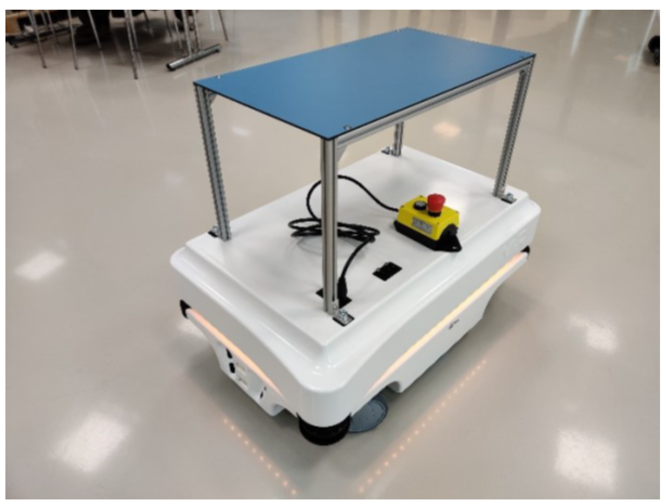
This section describes the chosen autonomous mobile robot and its parameters. The selected mobile robots are developed by the MiR company; specifically, a MiR100 model was found for the demonstration tasks. This mobile robot is designed for transportation purposes and to automate logistics. Its designation is based on the weight it can transfer (100 kg). The model is equipped with advanced sensors, which means that the robot moves autonomously in the environment and responds to surrounding obstacles.
Table 1 provides basic information about the model [
19].
The selected model is the smallest one and, thanks to its dimensions, it is possible to navigate this robot into the production line. The top of the robot is also supplemented by a superstructure, on which the products from the production line are placed.
Figure 1 shows a photo of the mentioned mobile robot.
All configurations and settings of the mobile robot (MiR, MiR FLEET, WISE digital input, and output cards) are performed via a Web interface. Each web interface is different according to the needs of a particular device but is very similar in style [
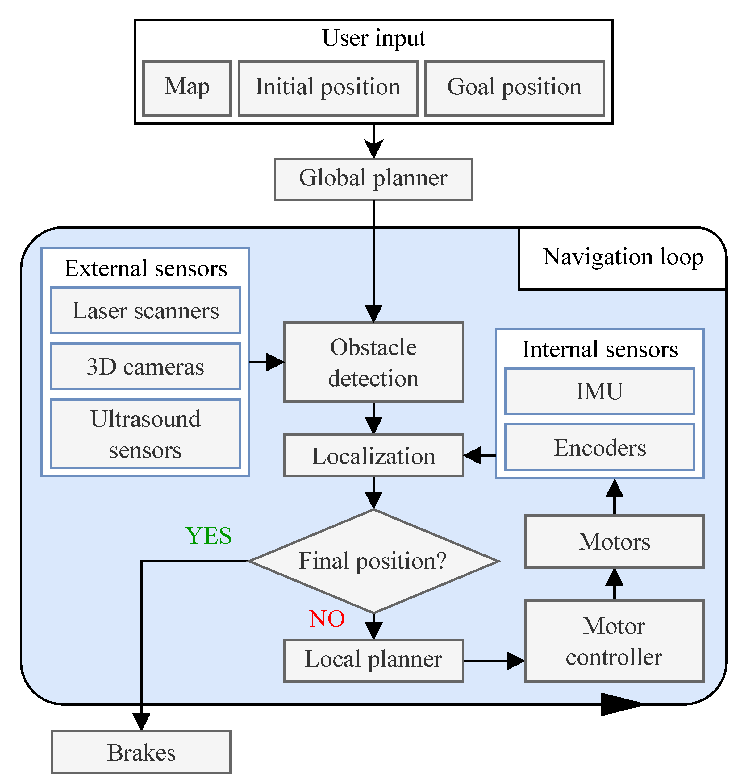
10]. The navigation system is the core of the autonomous mobile robot. Its goal is to plan the route from starting point A to destination point B. These points are determined by the user, but the journey is already planned completely, autonomously, and automatically. An advanced navigation system, which consists of several parts, is responsible for determining the correct route and navigating the robot to the destination.
Figure 2 shows the principle of system operation. For clarification, it should be noted that IMU is inertial measurement unit.
2.1. Navigation System
For the navigation system to be able to find the route, it needs initialization data according to which it will plan the route. The user enters the information about where the robot should arrive. However, to plan a route, the mobile robot must also know the space in which it moves and its current position. For orientation in space, a virtual map is used, which is stored in the robot’s memory and contains data about all walls and obstacles. This map must be created before it is possible to use the mobile robot. Once the virtual map is created, points can be inserted into it through which the robot moves. However, it is possible to edit the map using zones, landmarks, and special planning rules.
After obtaining all the data for the start of route planning, the route is planned by the robot itself, which is in charge of the global planning system. This is an algorithm that generates a route to the desired point. However, it is important that the global planning system generates the path to the destination only once and follows only the fixed obstacles that are recorded on the virtual space map. This means that if a new obstacle arises in the environment of the robot that is not recorded on its virtual map, the global planning system does not know about this obstacle and plans a journey despite this obstacle. The planned route is shown on the map or on the dashboard using dots. If the robot cannot complete the move, planning is terminated with an error message, and the whole mission is suspended.
The local planning system, unlike the global planning system, runs in a continuous cycle throughout the robot’s operation. Its task is to respond to obstacles in the immediate vicinity of the robot that are detected by sensors and not recorded on a virtual map. In the case of detecting an obstacle on a route, the local planning task is to determine the route through which the mobile robot can bypass the obstacle. If an obstacle is out of range or out of the sensor’s field of view, the system does not take this obstacle into account. In a route that is created using global planning, the robot dodges the obstacle only to embrace the obstacle and then returns to the generated original route. The mobile robot route can be blocked so that the system cannot find a detour route. In this case, the mobile robot has a set count of attempts, that is, how many times the robot tries to find a new route. The route can be blocked, for example, by a person who just walks through and then clears the way. If the mobile robot does not find its way in any of the set attempts, it pauses the active mission and waits for further instructions.
2.2. Obstacle Detection
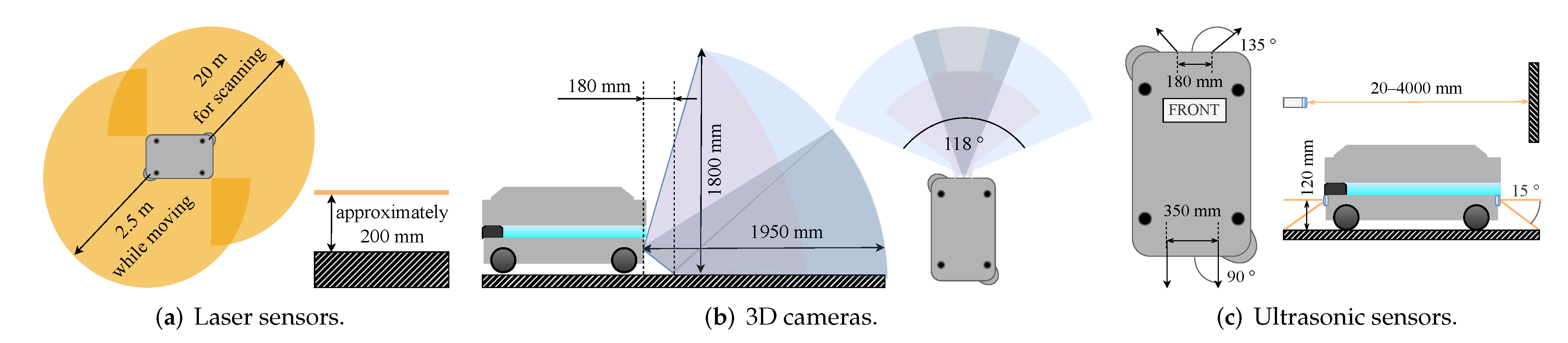
The obstacle detection system is constantly active, and its main purpose is to detect obstacles around the robot. Information about the current location of surrounding obstacles is also used to determine the current position of the mobile robot on the map or when placing the mobile robot on the map. Three types of sensors are used to detect obstacles. These are laser sensors, ultrasonic sensors, and 3D cameras.
Laser sensors: The MiR100 mobile robot is equipped with a pair of SICK S300 laser sensors. Each sensor has a viewing angle of 270
and is placed in opposite corners of the mobile robot to cover all 360
around the robot (
Figure 3a). However, these sensors have several limitations. They can only detect obstacles at a height of 200 mm from the floor and cannot detect transparent obstacles (glass). For some reflective surfaces, the data may be inaccurate. False obstructions may be detected when the sensor is exposed to direct light.
Three-dimensional cameras: Another way to detect obstacles is with a pair of Intel RealSense
cameras on the front; see
Figure 3b. The cameras are intended for indoor navigation only, not as obstacle detection safety sensors. An important feature is the ability to detect the height of individual obstacles in the environment. According to this, the mobile robot can determine whether it will fit under the obstacle or not. The height of the mobile robot is set manually in the web interface. The pair of cameras occupy a space from 180 to 1950 mm in front of the robot with a viewing angle of 118
and a height of 1800 mm. Three-dimensional cameras also have several limitations. Unlike 360
laser sensors, they can only detect objects in front of a mobile robot. They cannot detect transparent or reflective objects or steps that descend. Distance determination may be inaccurate when detecting objects with repeating patterns. False obstructions can be detected when exposed to direct light.
Ultrasonic sensors: The robot is equipped with four ultrasonic sensors; see
Figure 3c. Two sensors are located in the back of the mobile robot and two are located in the front wheels of the mobile robot. Ultrasonic sensors are used to detect obstacles that could not be detected with a laser sensor or 3D cameras. The front sensors can detect obstacles of 10 to 200 mm, while the rear sensors detect obstacles at distances of 10 to 350 mm.
Figure 3.
Obstacle detection system [
20].
Figure 3.
Obstacle detection system [
20].
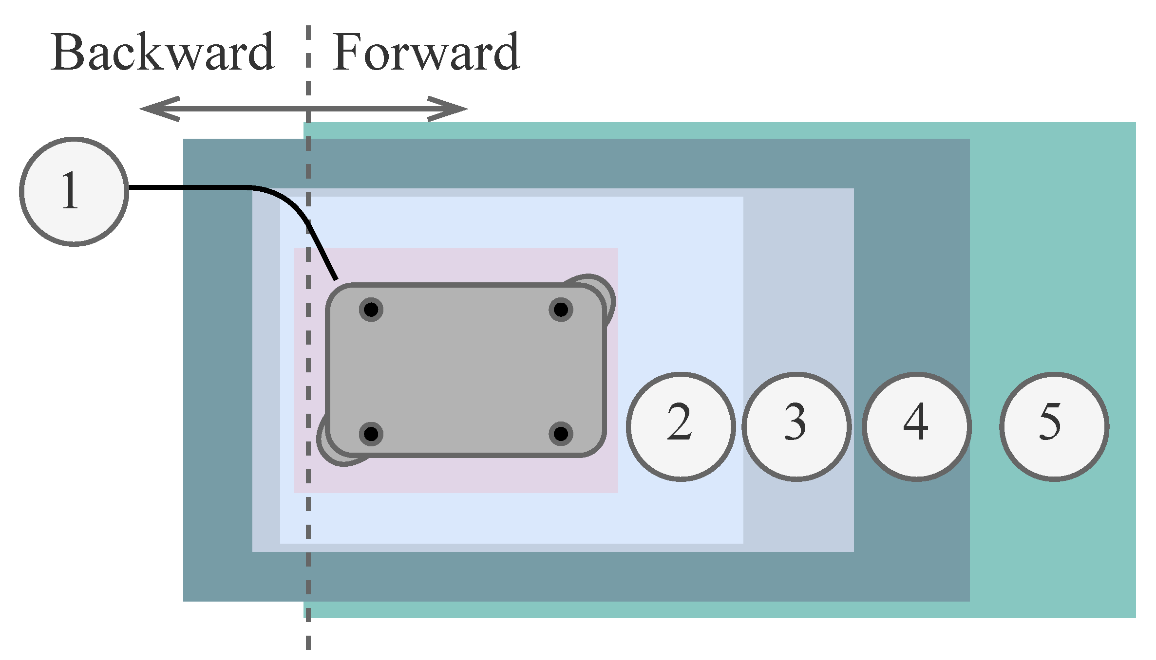
The information from all mentioned sensors has a fundamental effect on the speed of the robot’s movement in the given space, see
Figure 4,
Table 2 and
Table 3. When a mobile robot travels at low speed, it primarily guards the space and obstacles in its immediate vicinity. However, if the mobile robot is traveling at a higher speed, it has much more space to be able to brake if an obstacle occurs. The robot’s speed automatically changes according to the conditions of the environment in which the mobile robot moves. When the robot moves forward, it is also taking care of the situation behind him. The maximum speed of the robot can be limited using commands during mission creation.
In Zone 1 in
Table 2, you can see a negative speed for the forward direction. It should be noted that in this zone, the robot performs 3 consecutive actions: reversing, stopping, and slowly moving forward. Zone 5 then shows the maximum forward speed of the robot. Then, in Zone 1 in
Table 2, you can see the positive speed for the backward direction. It should be noted that in that zone, the robot performs 3 consecutive actions: forward, standstill, and slowly backward. Zone 5 then shows the maximum backward speed of the robot.
3. Analysis of the Use of Mobile Robots in SmartFactory
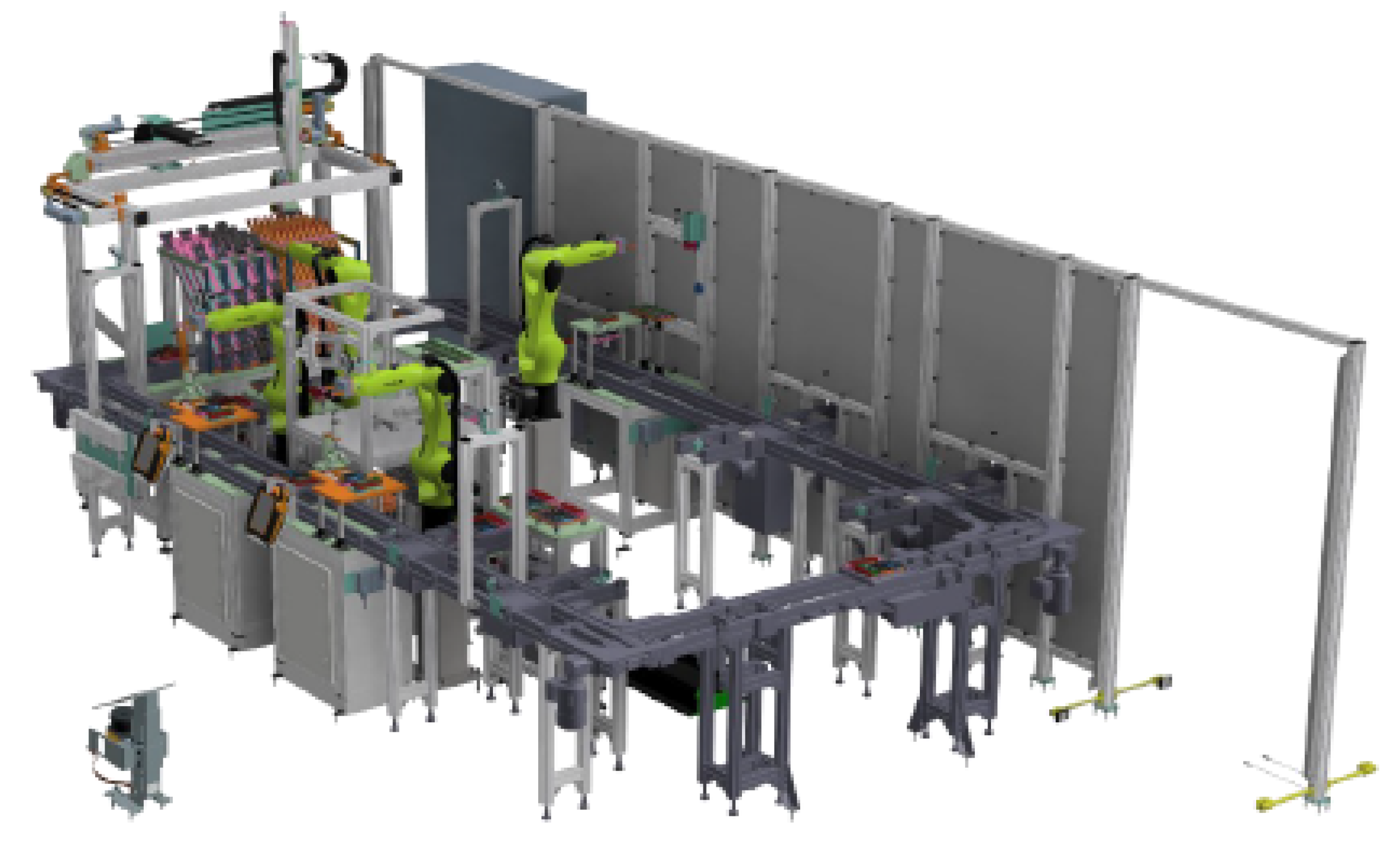
SmartFactory is a classroom, within a new CPIT TL3 building, specialized in Industry 4.0 technologies such as modern manufacturing processes, robotics, and automation, and a fully automated production line is also located there. This production line contains a digitized production process with Industry 4.0 elements such as product variability, predictive maintenance, augmented reality, or digital twins. The 3D model of the SmartFactory production line can be seen in
Figure 5. Here, two types of products are manufactured in a fully automated process. The line enables product assembly using a fully automated process, product testing, product inspection, and product layout.
The products can be manufactured using individual components available in the warehouse; in addition, they must be placed on a platform. The platform is used for transfers between individual workplaces. A total of four robotic arms are installed on the production line. The first is used to operate the warehouse (component removal, product disassembly, product export from the line, and more). For this purpose, it is equipped with two tools that are automatically changed as needed. The other two arms are part of two fully automated production areas for the assembly of products. The third is used for automated product disassembly; the components are then stored back in the warehouse. The last robotic arm is part of the manual workplace for cooperation with staff or students. There are also two workplaces for fully manual staffing. There is also a test station for the final inspection of products. Electrical and visual inspections can be performed.
The request to start the production of products is entered through visualization from the control workplace. When ordering a product, it is possible to choose the type of product and the electronics that the product will contain. In the case of a second product, you can choose the color of the individual plastic cubes that will be placed on the product. The product may include electronics for the function of a pedometer, thermometer, or heart rate monitor.
3.1. Products
The first type of product consists of electronics and plastic parts printed using a 3D printer. It is called product design. There are three types of electronic devices: a pedometer, a thermometer, and a heart rate monitor. Each electronic piece belongs to a slightly modified plastic case. This product cannot be dismounted, it is fully functional, and it is intended as a customer product.
The second product consists of individual plastic parts and offers more options for individualization by the customer. As with the first product, it is possible to choose the type of electronics (pedometer, thermometer, heart rate monitor) and also the color of each of the eight plastic cubes. After the cubes are mounted on the base plate, the electronics are inserted into the resulting frame. The finished product is presented using a mobile robot on the premises of SmartFactory and is then returned to the line, where the product is automatically disassembled into individual components, and then stored in the warehouse.
3.2. Use of an Industrial Mobile Robot
The autonomous mobile robot in combination with an automated production line also offers the possibility of a fully automated production process and subsequent delivery of the product. The mobile robot is able to take the finished product from the line space and deliver it to the required location. It takes over the product directly on the premises of the line, where it arrives automatically. The KUKA [
21] robotic arm, located in the middle of the production line, is used to move the product from the belt of the production line to the mobile robot. Unlike other robotic arms, it is equipped with a carriage, thanks to which it can move around the entire space of the production line.
The robot loading position is located in relatively narrow spaces below the conveyor belt. The mobile robot has to approach this position autonomously with high accuracy. After receiving the product, the mobile robot moves according to the specific implementation.
4. Experimental Setup
In this section, experimental delivery routes and the integration of a mobile robot into the SmartFactory production line are presented. As mentioned above, the production line produces two types of products. The production line does not contain any collection point for the final product and is surrounded by security features that prevent the possibility of entering the line. For this reason, the MiR100 mobile robot took care of the product’s journey from the line to the customer. Since the production line produced two types of products, two possible implementations were proposed.
For navigation in a selected space, the robot used a virtual map. It was necessary to create this map before the robot started moving. The virtual map contained information on obstacles, zones, robot positions, markers, and other elements needed to control the robot. The virtual map could be created directly on the Web interface of the mobile robot. Since the robot oriented itself on the map using fixed, unchanging obstacles, it was recommended to have at least 60% of them on the map. The environment had to stay the same over time as much as possible. If the conditions changed rapidly, a new virtual map had to be created. Once the virtual map was created, it was possible to create missions.
4.1. Delivery and Presentation of the Product
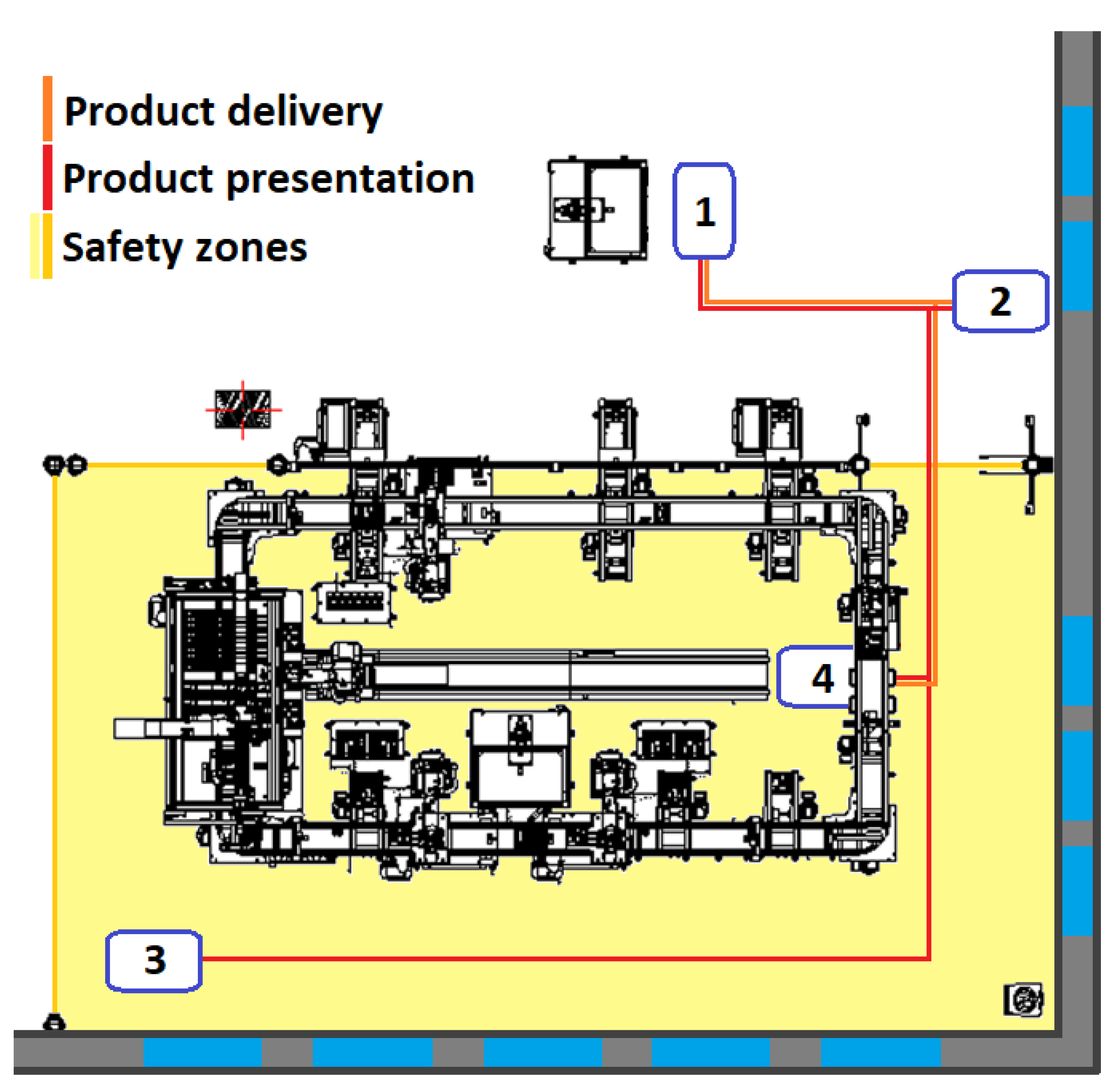
The purpose of the first implementation of the mobile robot was to ensure the delivery of the finished product design from the line to the customer.
Figure 6 shows the route of presentation and delivery of the product design. In the starting position, the robot was in front of the charging station or was charging. The customer used visualization to order a product, which the line then produced and passed the information to the mobile robot that the product was ready. The mobile robot reached the position on the production line where the product was handed over with the help of a robotic arm. The product was then removed from the line area, where the customer could take it over from the mobile robot. As soon as the customer removed the product, the mobile robot moved to a position in front of the charging station, where it waited for the next call from the line.
The second implementation of the mobile robot ensured the presentation of the assembled product produced in the SmartFactory line. The task of the implementation was to take the finished product, drive it along the route, and then return the product back to the line. The robot was in a starting position in front of or near the charging station, waiting for a signal that the product was assembled. When the signal was received, the mobile robot arrived at the charging position on the line and took the product back. It walked around the SmartFactory window with the product, then exited the line area so that any followers could view the product, and then returned to its position in the line. In this position, the product was unloaded from the mobile robot and returned to the production line where it was again disassembled. In this implementation, it was necessary for the mobile robot to approach the position with great precision when returning the product.
4.2. Cooperation with SmartFactory
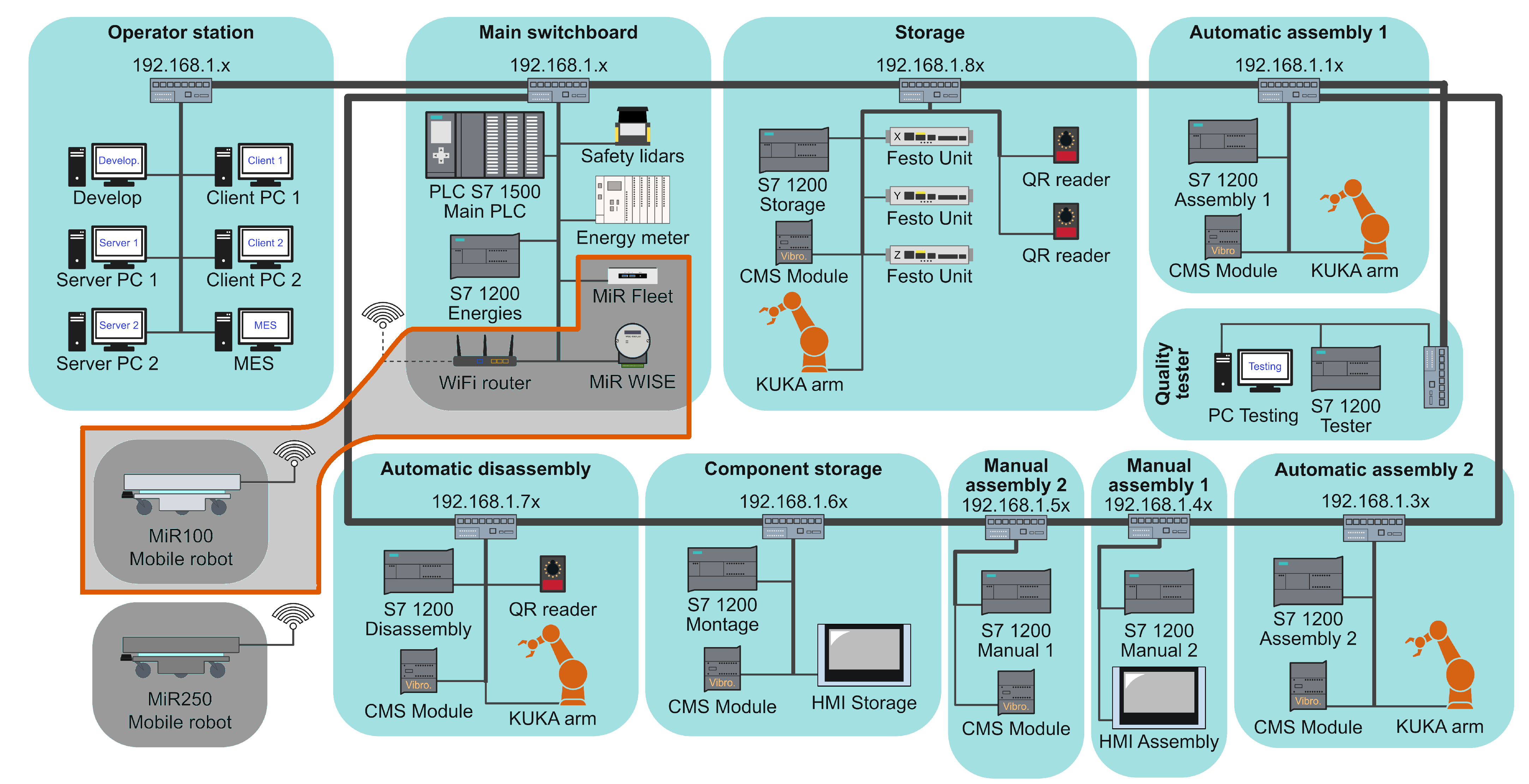
There was a local network within 192.168.0.x/24, which was used for the control systems, robotic arms, sensors, and other devices on the line. Additionally, a Wi-Fi router was used to connect mobile robots, laptops, or smartphones. Although the Wi-Fi router was part of the production line network, it was powered independently, so the mobile robot network worked even when the production line was off. See
Figure 7 for more detailed information.
Two other devices were also connected to this network, which communicated directly with the mobile robots. The first device was the MiR FLEET, which took care of the cooperation of several mobile robots. MiR FLEET is a web-based supervision application, that enables centralized control of multiple AMRs. The second device was the WISE module, which provided external communication with the mobile robot via digital inputs and outputs. It enabled communication between an AMR and the production line or some other device.
4.2.1. Communication
The task of the mobile robot was to automatically take over the products from the production line and transport them to the designated place. For this functionality, it was necessary to ensure communication between the line and the mobile robot. Communication was provided by the WISE-4050/LAN module. It is equipped with 4 digital inputs and 4 digital outputs. The module is connected to the line switchboard and communicates directly with the C system, which controls the production line using inputs and outputs. To pair a mobile robot with a WISE module, it is necessary to place them on the same network. After pairing, instructions to read the digital input or change the digital output can be entered into robot missions. Since 8 digital signals were used for communication between the mobile robot and the production line, it was necessary that both the mobile robot side and the line side, and the programmable logic controller (PLC) knew the exact purpose of the signal. Communication was also necessary for the need of shutting down the safety barriers and gates, as the robot would otherwise activate them and set up a disruptive process. For this reason, individual signals were assigned a specific meaning. All signals required for communication are listed below.
DO0: The mobile robot sends a signal that it is ready on the line to pick up the product;
DO1: The mobile robot sends a signal that it is ready on the product collection line (LEGO);
DO2: The mobile robot sends a signal that it is ready to call from the line;
DI0: The mobile robot receives a signal to arrive at the line;
DI1: The mobile robot receives a signal that it is loaded/unloaded;
DI2: The mobile robot receives a signal that it has finished.
4.2.2. Implementation
The program for MiR mobile robots was created using individual commands, such as logic functions, move functions, docking functions, and more. These functions were then grouped into so-called “missions”. The robot’s mission was therefore a grouping of commands that determined what the robot should do in a particular mission. Within the mission, the individual commands were executed sequentially and if the robot had already fulfilled all commands, the mission was terminated. Missions were launched to the robot via a web interface, and it was possible to add more missions to the queue for the robot to complete. If the mobile robot had no mission in the queue, nor did it perform any active mission, it stood still and waited for the mission to be assigned.
Movement and positioning
- -
Move: The mobile robot moves to a position on map;
- -
Docking: The mobile robot moves to a marker or charging station;
- -
Rel. move: The mobile robot moves to a relative position.
Logic functions
- -
Charging: The mobile robot starts charging;
- -
If: Conditioning decision function;
- -
Loop: Cycle repeated execution of commands.
WISE I/O module control
- -
Set output: Switch on/off the output on a WISE module;
- -
Read input: Read the actual value on the digital input of a WISE module;
- -
Wait for input: Detection of the input on a WISE module.
Other functions
- -
Mission call: Perform a mission in another mission;
- -
Light: Sets the style and color of the robot lights;
- -
Sound: The ability for the mobile robot to play a sound.
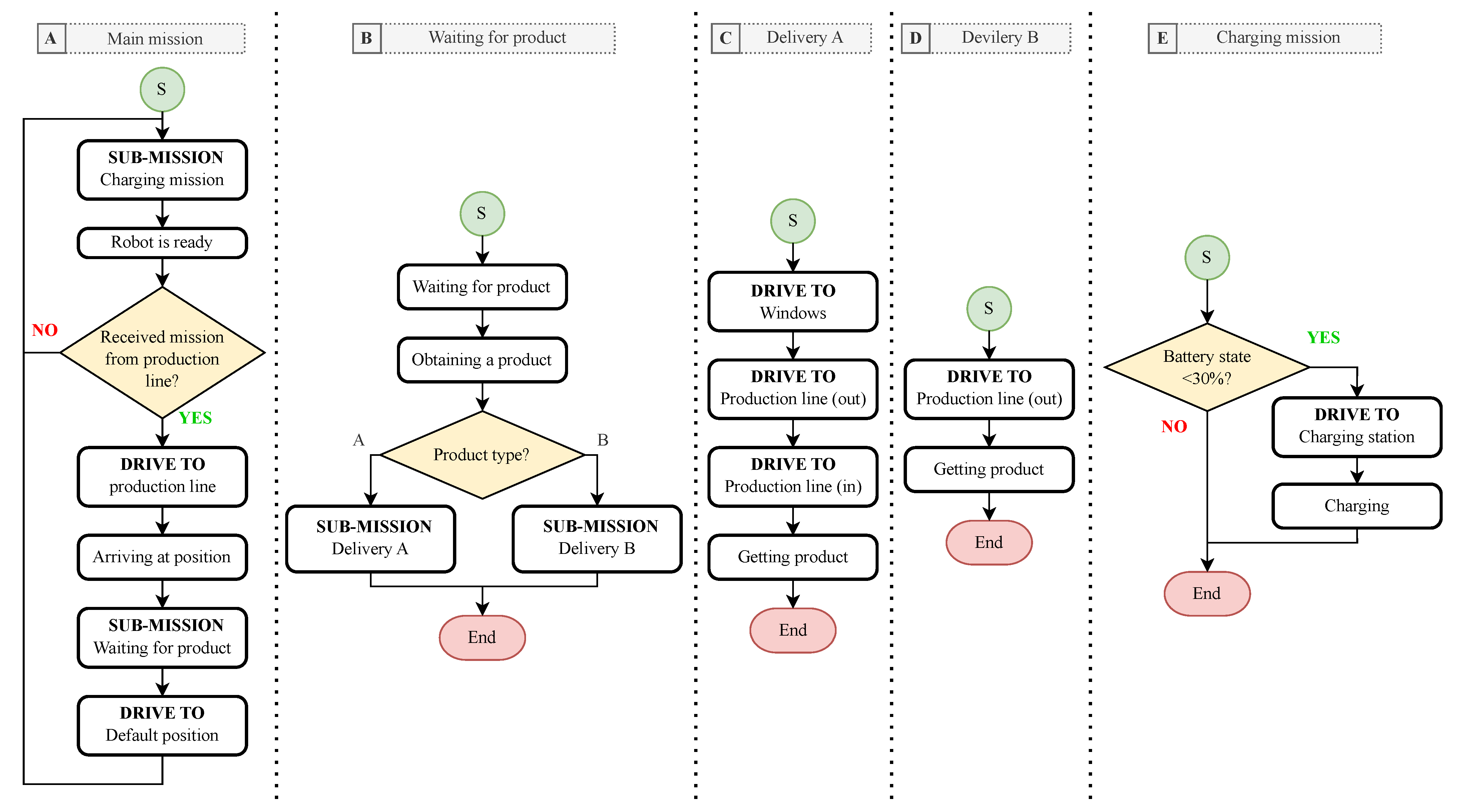
The mobile robot MiR100 had the task of communicating with the production line in SmartFactory and taking the manufactured products. According to the proposed implementation, the mobile robot took a pair of products from the line. Each pair of products had a different final delivery position, and the mobile robot had to recognize which product was currently being delivered. It received this information from the line. The mobile robot also monitored the level of the battery so that it could operate continuously and was always ready to take the product. The entire programming code was divided into five missions, where the first was the main mission, and the rest were submissions for specific actions; see
Figure 8.
- A:
Main mission
- B:
Waiting for product
- C:
Delivery A—LEGO product delivery mission
- D:
Delivery B—product design delivery mission
- E:
Charging mission
4.2.3. Precise Robot Positioning
In order to always be able to place the product in the same place on the robot superstructure, it was necessary for the mobile robot to approach the line in the loading position with great accuracy. If the mobile robot took the design of the product and then passed it on to the customer, this accuracy was not very necessary. However, if the mobile robot returned with a LEGO product and requested that the product be removed back to the line, an accuracy of a few millimeters was required. The mobile robot product loaded and unloaded the KUKA robotic arm, which always moved to the same position. This meant that when LEGO loaded a product onto a mobile robot, it expected the product to be in the same place when it was unloaded. The MiR100 mobile robot did not always move to the exact same position, and it was possible that when returning to the line, it was shifted by a few millimeters or even centimeters. The arm expected that the product would be in a completely different position. From this, three options were considered to achieve this.
Camera
The first and at the same time the most technologically demanding possible solution was the use of a camera. The camera would be placed on a robotic arm and recognize the position of the product by recognizing the shapes of objects. The robotic arm would tilt over the mobile robot and use a camera to determine the exact location of the product on the mobile robot. The camera would pass this location to the robotic arm, who would know exactly where the product is located and how to grasp the product. The camera solution has one major advantage, but also disadvantages. When using the camera, the robot could enter the line differently each time, and its accuracy would not be necessary. A big advantage would be the ability to move the product on the platform of a mobile robot. The camera would always detect the position of the product, even if it was moved or rotated in a different direction from the original position. This would allow the customer to view the product and then place it back on the mobile robot. The disadvantage of the solution is the price and the high technical complexity. To enable image recognition, it would be necessary to connect the camera to the line control system and create a program that recognizes products.
Distance Sensors
Distance sensors were another possible solution to make missions and paths more precise. In the first case, the sensors would be placed on the body of the mobile robot and would sense the exact distance from the selected obstacles. After approaching the line, the mobile robot would use sensors to check whether it was in the exact position and, if necessary, adjust its position. However, this solution encounters a problem in communication with the mobile robot. Communication with the MiR100 mobile robot using the WISE module only allows control of digital inputs and outputs. For the purpose of this solution, it would be necessary to transfer the analog value from the sensors to the robot. A second variant was the placement of sensors on the production line. Instead of detecting the position of the mobile robot, the sensors would sense the position of the product on the robot. When using two laser sensors, one would sense the position of the product on the X-axis, and the other would sense the sensor in the position on the Y-axis.
Markers
The last solution considered was to enter the line using markers. Markers are a direct solution for a mobile robot to ensure that it approaches positions with a certain accuracy. Several types of markers can be used to navigate the mobile robot. These are V, L, VL, and bar-markers. Each marker has a specific shape and dimension that must be strictly adhered to during production. The marker should be placed directly in front of the mobile robot in the position where the robot will approach. This solution is the most accurate and accuracy also depends on the marker type used.
The planning algorithm used input parameters from the configuration interface of the robot. It meant that it was possible to configure which type of marker was currently in use. Each time the robot was approaching the final position, it was scanning the area for a marker specified using a configuration interface.
5. Results
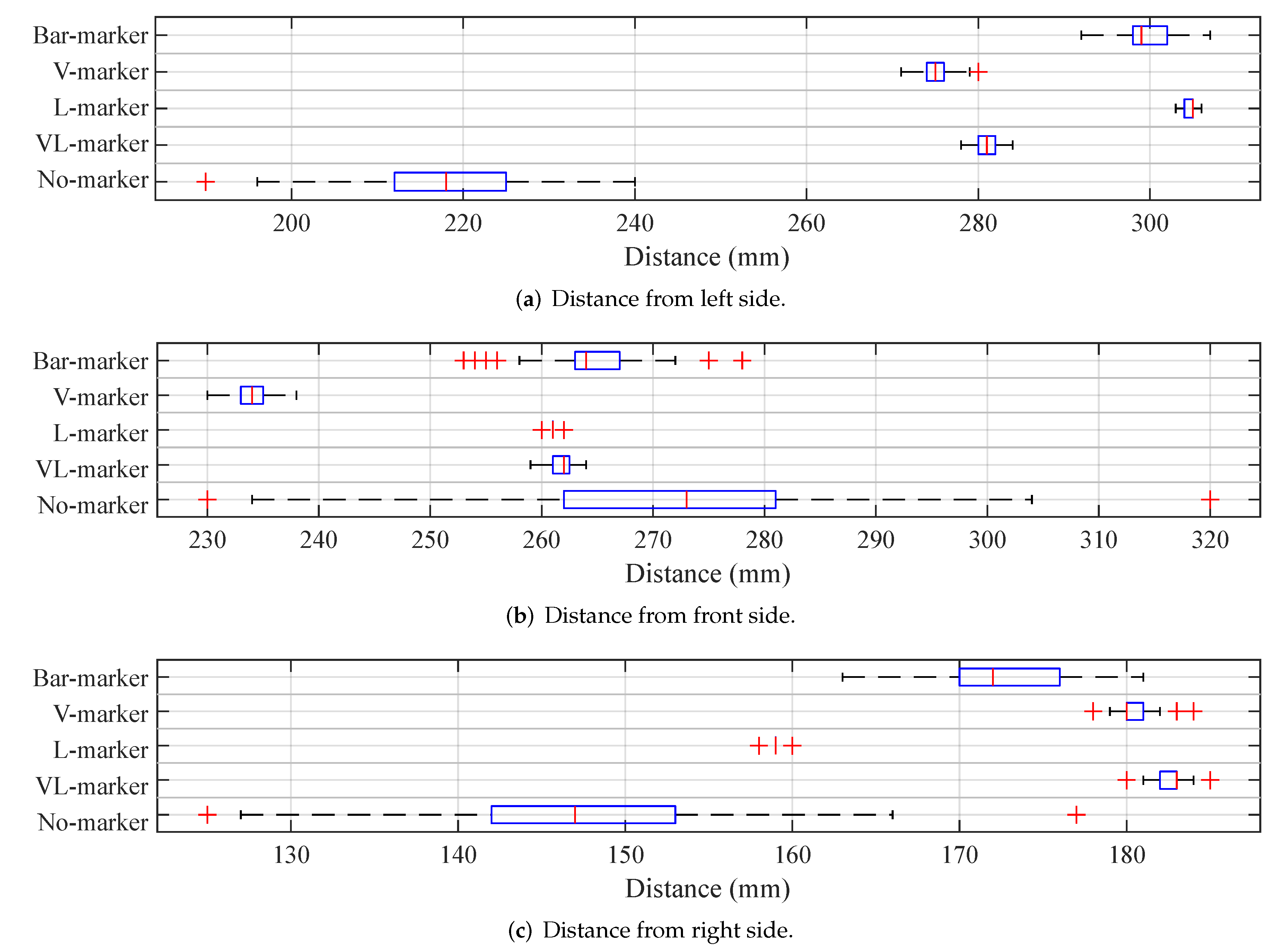
Several tests were performed to verify exactly how the mobile robot could approach positions. The tests included moving the mobile robot to a position on the map, but also to different types of markers. The manufacturer states that each type of marker provides a different accuracy, and of all types of markers, the VL-marker is listed as the most accurate.
During the testing, we checked three distances. Distance between the mobile robot and the line profile on the left and right sides. The third distance checked was the distance between the robot’s front and the rail to move the robotic arm. As part of the testing of each type of marker, a total of 100 robot entrances were performed on the lines. At each attempt, the mobile robot always drove out of the line area and then back to the position in the line, possibly using a marker. The data thus obtained were represented by a box plot and basic statistical indicators. The results demonstrated the accuracy with which the mobile robot approached a given location. The distance was read using three laser range finders.
5.1. Positioning without Marker
First, the accuracy of the position was tested in the absence of a marker. The mobile robot approached the position created on the virtual map. Since the robot guarded its surroundings and the line space was too narrow for the robot, it was necessary to place the position slightly in front of the line space. After approaching the position, a command was sent to the robot to use the command Relative move to move a certain distance forward into the line space. The command partially allowed the robot to drive into narrow spaces without the mobile robot detecting them as obstacles. The command Relative move had no effect on the accuracy of approaching the position on the map and only moved the robot on the given axis, always by the same distance.
From the test, it could be observed that if the robot only approached the position in the virtual map, it achieved a considerable inaccuracy. The variance of the measured values reached up to 25 mm in the case of the distance from the edge of the robot arm path. Thus, for AMR navigation, it was necessary to use the right type of marker to get the best results.
5.2. Using a VL-Marker
A VL-marker was used to specify the approach of the mobile robot to the position on the line. From the data from the manufacturer and distributor of robots, this is the most accurate marker, owing to which the mobile robot should achieve the highest accuracy.
Ideally, the marker should be placed in front of the robot. Due to the limited space in the line, the marker was placed slightly on the right side. During the initial creation of the marker, the robot approached directly opposite the marker. However, the markers allowed one to set the offset, and it was a matter of shifting or adjusting the final position of the robot on the marker. The offset could be set for the X-axis, the Y-axis, and the rotation.
5.3. Using an L-Marker
Another type of marker tested was the L-marker. Like other markers, it had exactly the given dimensions, which had to be observed with an accuracy of ±1 mm. For the use of the L-marker, no degree of accuracy was given with which the mobile robot could guide the marker.
5.4. Using a V-Marker
This marker was also used for AMR positioning. In shape, it contained the same “V” shape cutout as the VL-marker, but no longer contained another area to the right of the cutout, as the VL-marker did. It was therefore a smaller and lighter version of the VL-marker, which did not achieve greater accuracy than an L-marker.
5.5. Using a Bar-Marker
The bar-marker is a very simple type of marker. The bar-marker consists of two parts, which are built at a given distance from each other and between which the AMR moves. With this marker, we achieved the second worst results.
From the measured results, it can be observed that the L-marker further refined the approach of the robot to the exact position. The result of this test showed that thanks to the L-marker, the AMR could repeatedly approach the position with greater accuracy than with the VL-marker. The test, therefore, refuted the distributor’s claim that the VL-marker was the most accurate. For detailed information, see
Figure 9 and
Table 4.
During testing, the mobile robot encountered an error when it could not reach the L-marker in (b). The L-marker was placed as in (a) so that the mobile robot did not have a problem in position. The problem occurred only during the final shooting of the robot in parallel with the marker. Instead of turning, the robot got stuck in the shooting phase and moved back and forth about 5
. After checking the robot’s status through the web interface, the robot still performed the docking process and did not show any errors. Even after a certain time, the robot did not exit this cycle and it was necessary to end the program that was executed. The problem was solved by moving the marker to another location and reading the marker onto the map. After that, the problem did not manifest itself.
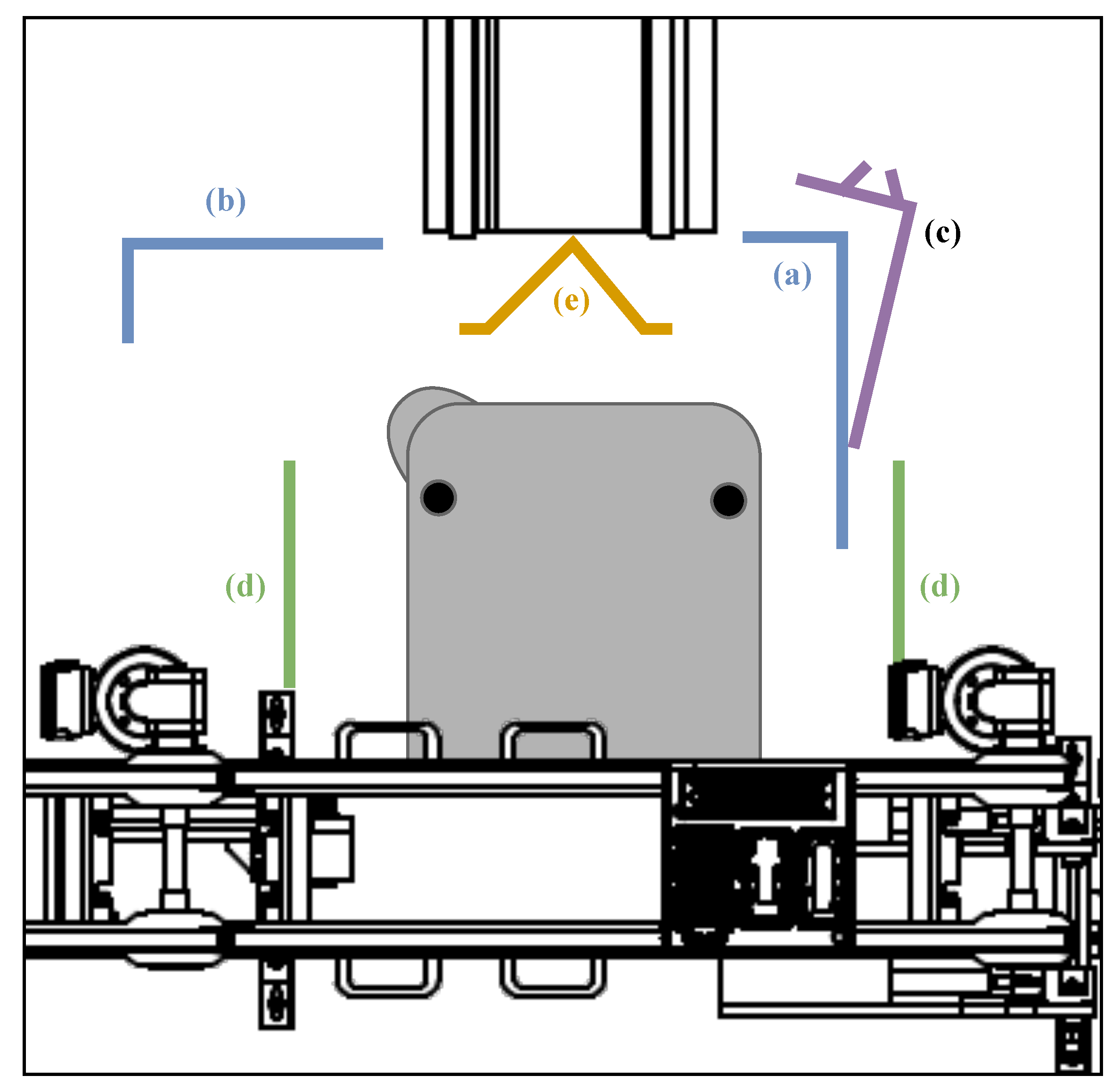
Figure 10 describes the positioning of the different markers during the test according to the manufacturer’s recommendations.
Another complication occurred when adding a marker to a virtual map. If the mobile robot was chosen to detect the position of the marker in the environment, it could not determine the position of the marker. Instead of the real L-marker, the mobile robot detected the corner of the production line as the L-marker. This was despite the completely inconsistent dimensions, which differed significantly from the given dimensions for the L-marker. Therefore, when the L-marker was loaded, an obstacle was placed in this corner so that it would no longer be detected as a marker.
6. Conclusions and Future Work
This paper described the implementation of an industrial autonomous mobile robot MiR100 in SmartFactory. The production line produced a pair of products that were not distributed outside the premises of the line, and therefore it was not possible to take possession of the produced product. For this reason, the mobile robot was used to distribute the finished products around the SmartFactory premises. The line produced design products and customizable LEGO products. The design product was intended for the target customer, to whom the product was delivered by the mobile robot. The LEGO product was not intended for customers and was only used to demonstrate what the line was capable of. The mobile robot drove the LEGO product through the SmartFactory premises and then returned the LEGO product back to the line, which then disassembled it into its individual components.
In the first step of the implementation, it was necessary to create a virtual map of the SmartFactory, according to which the mobile robot had to orient itself in space. Individual obstacles, forbidden zones, positions, and markers necessary for the implementation were inserted into the map. The SmartFactory contained its own wireless fidelity (Wi-Fi) network, to which all the devices needed to operate the robot and communicate with the production line were connected. Communication with the line was provided by the WISE module, which contained four digital inputs and four digital outputs. Each digital signal had a clear meaning and was sufficient for communication between the mobile robot and the production line. The program for operating the production line was divided into individual missions. In order to start the operation of the production line, the main mission had to be started on the mobile robot, which was already calling the next sub-mission. The manufactured products were transferred to the mobile robot by a robotic arm. When loading products onto the robot, the positioning accuracy of the mobile robot was not important. When unloading the LEGO product that the robotic arm returned to the line, a high precision was required to position the robotic arm correctly. This accuracy was not achieved by the mobile robot, so we came up with three suggestions to improve the accuracy. Using a camera to determine the exact position of the product, using external sensors to accurately position the mobile robot, and using markers to increase the positioning accuracy. After consulting and considering the complexity of the solution, we decided to use markers. Since the mobile robot supported multiple types of markers, we tested their accuracy. The L-marker came out best in the tests.
The result was a fully automated process for operating the production line. The MiR100 mobile robot could respond to a call from the line, then arrive to collect the product, take it over and make its presentation or delivery to the desired location. The operation also included battery monitoring and automatic recharging if necessary.
We see the potential for improving the way we communicate in future developments. The communication used by the WISE module is limited to data types and a small number of inputs and outputs. During further development, communication via a representational state transfer API (REST API) supported by a mobile robot is planned. In addition, the robotic arm will be retrofitted with a camera. If the robotic arm was equipped with a camera, the capabilities of the mobile robot would be expanded. Without the camera, the LEGO product must remain in the same position as the robotic arm. Using the camera, the LEGO product could be removed from the mobile robot and then returned. The viewer would then be able to view the LEGO product themselves. The camera would then identify the position of the LEGO product and relay this information to the robotic arm.
The main contribution and the results obtained were that a statistical analysis of the mobile robot’s run-up on different types of markers was performed to determine the repeated run-up accuracy. Here, it was found that the most suitable marker type was the L type, where the mobile robot had a repetitive error of ± 3mm. This output is essential for applications where the industrial arm is transferring products to the mobile robot, but also for the reverse, where products are removed from the mobile robot. Repeated pick-up accuracy is therefore crucial. Despite the fact that MiR offered a ready-made solution, it was necessary to verify the behavior of the robot in real conditions, where its navigation was hampered, in particular by the narrow space in the production line area, the conveyor belt which was in a position partially above the mobile robot at the moment of the robot’s run-up, and the number of structural elements in close proximity to the robot. All these elements can affect the accuracy of the robot’s sensors and scanners. In such a confined space, the robot is constrained by its own safety zone settings, which eliminate the possibility of robot movement and may limit the final positioning accuracy compared to the accuracy declared in the manufacturing documentation.
Author Contributions
Conceptualization, R.H., R.B. and R.J.; methodology, R.H. and R.B.; software, R.H. and R.B.; validation, R.H., R.B. and R.J.; formal analysis, R.J.; investigation, R.H. and R.B.; resources, J.K.; data curation, R.H. and R.B.; writing—original draft preparation, R.H., R.B. and R.J.; writing—review and editing, R.H., R.B. and R.J.; visualization, R.H. and J.K.; supervision, J.K.; project administration, J.K.; funding acquisition, J.K. All authors have read and agreed to the published version of the manuscript.
Funding
This work was supported by the European Regional Development Fund in Research Platform focused on Industry 4.0 and Robotics in Ostrava project CZ.02.1.01/0.0/0.0/17_049/0008425 within the Operational Program Research, Development and Education. This work was also supported by the Virtual Instrumentation for test and measurement systems SP2022/88.
Institutional Review Board Statement
Not applicable.
Informed Consent Statement
Not applicable.
Data Availability Statement
Not applicable.
Conflicts of Interest
The authors declare no conflict of interest.
Abbreviations
The following abbreviations are used in this manuscript:
| AMR | Autonomous mobile robot |
| API | Application programming interface |
| CPIT TL3 | Building in VSB campus with sophisticated management system |
| IMU | Inertial measurement unit |
| KUKA | Robotic arm from KUKA company |
| MiR | Mobile Industrial Robots |
| MiR100 | Autonomous mobile robot from the MiR Company |
| MiR FLEET | Centralized control station for MiR robots |
| MiR WISE | I/O module for MiR robots |
| PLC | Programmable logic controller |
| SICK S300 | Type of laser sensor |
| REST API | Representational state transfer API |
| Wi-Fi | Wireless fidelity |
References
- Chen, X.Q.; Chen, Y.Q.; Chase, J.G. Mobiles Robots—Past Present and Future. In Mobile Robots-State of the Art in Land, Sea, Air, and Collaborative Missions; IntechOpen: Vienna, Austria, 2009. [Google Scholar] [CrossRef]
- Siegwart, R.; Nourbakhsh, I.R.; Scaramuzza, D. Introduction to Autonomous Mobile Robots, 2nd ed.; MIT Press: Cambridge, MA, USA, 2011. [Google Scholar]
- McMorris, B. A History Timeline of Industrial Robotics; Futura Automation: Bengaluru, India, 2019. [Google Scholar]
- Alatise, M.B.; Hancke, G.P. A Review on Challenges of Autonomous Mobile Robot and Sensor Fusion Methods. IEEE Access 2020, 8, 39830–39846. [Google Scholar] [CrossRef]
- Marques, F.; Gonçalves, D.; Barata, J.; Santana, P. Human-Aware Navigation for Autonomous Mobile Robots for Intra-factory Logistics. In Proceedings of the 6th International Workshop, Symbiotic 2017, Eindhoven, The Netherlands, 18–19 December 2017; Ham, J., Spagnolli, A., Blankertz, B., Gamberini, L., Jacucci, G., Eds.; Springer International Publishing: Cham, Switzerland, 2018; pp. 79–85. [Google Scholar] [CrossRef]
- Majchrzak, M. AMR market expands rapidly: The market for autonomous mobile robots (AMRs) is growing fast, and there is a lot of demand globally for them in traditional automation, in non-automotive sectors. Control. Eng. 2020, 67, M11. [Google Scholar]
- Fragapane, G.; Hvolby, H.H.; Sgarbossa, F.; Strandhagen, J.O. Autonomous Mobile Robots in Hospital Logistics. In Proceedings of the Advances in Production Management Systems. The Path to Digital Transformation and Innovation of Production Management Systems; Lalic, B., Majstorovic, V., Marjanovic, U., von Cieminski, G., Romero, D., Eds.; IFIP Advances in Information and Communication Technology; Springer International Publishing: New York, NY, USA, 2020; pp. 672–679. [Google Scholar] [CrossRef]
- Surmann, H.; Nüchter, A.; Hertzberg, J. An autonomous mobile robot with a 3D laser range finder for 3D exploration and digitalization of indoor environments. Robot. Auton. Syst. 2003, 45, 181–198. [Google Scholar] [CrossRef]
- Kramer, J.; Scheutz, M. Development environments for autonomous mobile robots: A survey. Auton. Robot. 2007, 22, 101–132. [Google Scholar] [CrossRef]
- Chen, H.; Cheng, H.; Zhang, B.; Wang, J.; Fuhlbrigge, T.; Liu, J. Semiautonomous industrial mobile manipulation for industrial applications. In Proceedings of the 2013 IEEE International Conference on Cyber Technology in Automation, Control and Intelligent Systems, Nanjing, China, 26–29 May 2013; pp. 361–366. [Google Scholar] [CrossRef]
- Unger, H.; Markert, T.; Müller, E. Evaluation of use cases of autonomous mobile robots in factory environments. Procedia Manuf. 2018, 17, 254–261. [Google Scholar] [CrossRef]
- Autonomous Mobile Robot (AMRs) Types and Uses; Conveyco: Bristol, UK, 2020.
- Panigrahi, P.K.; Bisoy, S.K. Localization strategies for autonomous mobile robots: A review. J. King Saud Univ.-Comput. Inf. Sci. 2021, 34, 6019–6039. [Google Scholar] [CrossRef]
- Fragapane, G.; De Koster, R.; Sgarbossa, F.; Strandhagen, J.O. Planning and control of autonomous mobile robots for intralogistics: Literature review and research agenda. Eur. J. Oper. Res. 2021, 294, 405–426. [Google Scholar] [CrossRef]
- Tzafestas, S.G. Mobile Robot Control and Navigation: A Global Overview. J. Intell. Robot. Syst. 2018, 91, 35–58. [Google Scholar] [CrossRef]
- Iqbal, J.; Xu, R.; Sun, S.; Li, C. Simulation of an Autonomous Mobile Robot for LiDAR-Based In-Field Phenotyping and Navigation. Robotics 2020, 9, 46. [Google Scholar] [CrossRef]
- Gatesichapakorn, S.; Takamatsu, J.; Ruchanurucks, M. ROS based Autonomous Mobile Robot Navigation using 2D LiDAR and RGB-D Camera. In Proceedings of the 2019 First International Symposium on Instrumentation, Control, Artificial Intelligence, and Robotics (ICA-SYMP), Bangkok, Thailand, 16–18 January 2019; pp. 151–154. [Google Scholar] [CrossRef]
- CPIT TL3—Smart Factory. Available online: http://smartfactory.vsb.cz/index.html (accessed on 20 July 2022).
- Mobile Robot from Mobile Industrial Robots–MiR100. Available online: https://www.mobile-industrial-robots.com/solutions/robots/mir100/ (accessed on 20 July 2022).
- User Guide for MiR100 Autonomous Mobile Robots. 2021. Available online: https://gibas.nl/wp-content/uploads/2021/01/mir100-user-guide_31_en.pdf (accessed on 20 July 2022).
- KUKA—Industrial Intelligence 4.0: Beyond Automation. Available online: https://www.kuka.com/ (accessed on 20 July 2022).
| Publisher’s Note: MDPI stays neutral with regard to jurisdictional claims in published maps and institutional affiliations. |
© 2022 by the authors. Licensee MDPI, Basel, Switzerland. This article is an open access article distributed under the terms and conditions of the Creative Commons Attribution (CC BY) license (https://creativecommons.org/licenses/by/4.0/).


