Review

Electrospinning-Based Carbon Nanofibers for Energy and Sensor Applications

Department of Materials Science and Engineering, Gachon University, 1342 Seongnam-Daero, Sujeong-Gu, Seongnam-si 13120, Korea
*
Author to whom correspondence should be addressed.
Appl. Sci. 2022, 12(12), 6048; https://doi.org/10.3390/app12126048
Submission received: 23 May 2022 / Revised: 10 June 2022 / Accepted: 13 June 2022 / Published: 14 June 2022
(This article belongs to the Special Issue Practical Application of Functionalized Carbon-Based Nanomaterials)

Abstract

:
Carbon nanofibers (CNFs) are the most basic structure of one-dimensional nanometer-scale sp2 carbon. The CNF’s structure provides fast current transfer and a large surface area and it is widely used as an energy storage material and as a sensor electrode material. Electrospinning is a well-known technology that enables the production of a large number of uniform nanofibers and it is the easiest way to mass-produce CNFs of a specific diameter. In this review article, we introduce an electrospinning method capable of manufacturing CNFs using a polymer precursor, thereafter, we present the technologies for manufacturing CNFs that have a porous and hollow structure by modifying existing electrospinning technology. This paper also discusses research on the applications of CNFs with various structures that have recently been developed for sensor electrode materials and energy storage materials.

1. Introduction

The sp2 carbon structure is often used in research due to its excellent electrical and mechanical properties. Among them, carbon nanofibers (CNFs) are the most popular materials because they can be mass-produced with a simple manufacturing process and have excellent chemical stability. In addition, the electrical and mechanical properties of CNFs can be adjusted by varying the heat-treatment temperature. This means that heat treatment at a very high temperature of up to 2500 °C may be required to induce the high crystallinity of sp2 carbon and maximize the electrical properties, but amorphous CNFs can be obtained even at a low temperature of below 800 °C [1,2,3,4,5,6,7,8,9,10]. Also, by modifying the type of precursor molecule, which is converted to carbon during the heating process, components other than carbon can be easily introduced into the structure, thus changing the chemical properties [11,12,13].
The most common method used to prepare CNFs is the vapor-deposition method, in which a mixture of hydrocarbon molecules (such as methane and ethylene) having a small molecular weight grows carbon by reacting with a metal catalyst. By using this method, CNFs with uniform performance can be obtained. In addition, the performance of CNFs can be diversified by using different mixtures of various hydrocarbon molecules and metal catalysts [14,15,16]. However, this method has a disadvantage in that it is difficult to obtain a large number of CNFs inexpensively. The other method is to reshape the carbon precursor polymer (such as polyacrylonitrile (PAN) and polyvinyl alcohol (PVA)) by using a spinning method such as melt-spinning, wet-spinning, and electrospinning [17]. The advantage of the spinning methods is that they can easily produce large amounts of carbon fiber both on a laboratory and industrial scale. Among them, the electrospinning method, which generates uniform polymer nanofibers from polymer solutions using electromagnetic force, has been widely used [18]. The prepared polymer nanofibers were changed into sp2 carbon material after a carbonization process to generate CNFs. Recently, research has been actively conducted to improve the electrical and chemical performance of CNFs by introducing metal and metal-oxide components into the carbon and changing the structure of CNFs using an electrospinning method [19,20]. In particular, a carbon nanostructure with a maximized surface area was prepared by introducing pores and multi-channel structures to CNFs [21].
CNFs are widely used as sensor-electrode materials because they not only have a high surface-to-volume ratio but also enable rapid electron transfer due to their one-dimensional structure [22]. In particular, using a simple functional group introduction process, molecules that can easily detect the analyte can be introduced onto the surface, which can be applied as a sensor electrode material [23,24]. In addition, CNFs are also widely used as an energy storage material because metal and metal oxides can be easily incorporated into CNFs and micropores can be formed [25,26]. Recently, active attempts have been made to manufacture CNFs with a maximized surface area using a simple chemical treatment method and they are applied in a variety of energy storage systems [27,28,29].
The aim of this paper is to present various CNFs synthesized based on the electrospinning method and introduce them to applications in sensors and as energy storage materials. First, various types of polymer carbon precursors used in electrospinning are introduced and their modification into a carbon structure is described. After that, various types of electrospinning methods are suggested, and the structural deformation of CNFs generated by these methods is mentioned. Common electrospinning can produce a large number of uniform polymer fibers that act as the precursor for carbon. The combination of different materials can greatly alter the structure of CNTs and their properties for the desired applications. Finally, the detailed application of CNFs with different structures as sensor electrodes and energy storage materials is explained.

2. Electrospinning of Carbon Precursor Polymer

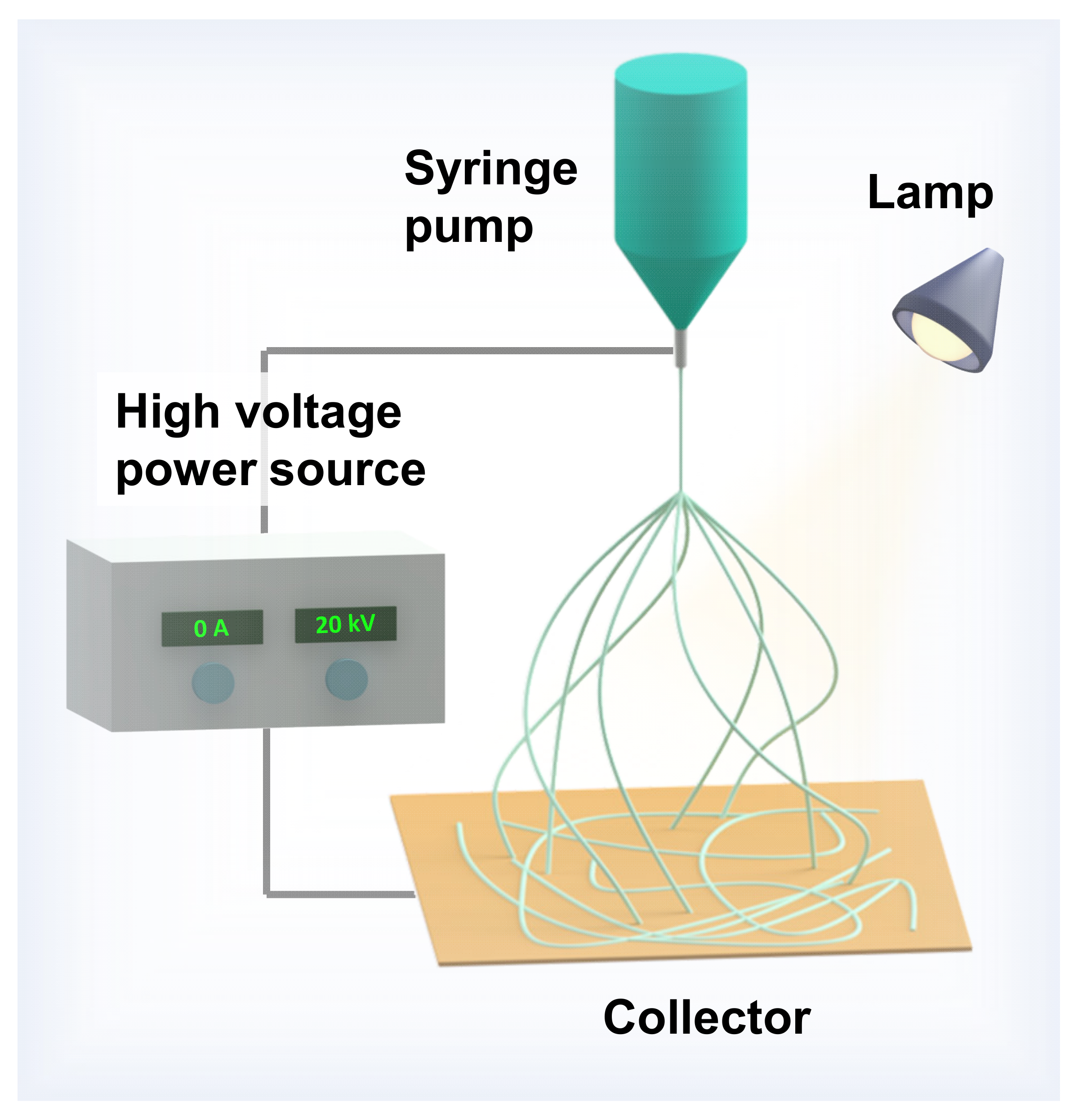
2.1. Setup and Conditions for Electrospinning

The electrospinning machine consists of three main components: a syringe pump, a high-voltage power supplier, and a collector (Figure 1). Depending on the used material, the collector can be a simple planar-type metal plate or rump-type equipment. The setup of basic electrospinning is so simple that it has become available to almost everyone [30]. It has been found that both a direct-current and an alternating-current power supply can be used in the electrospinning system. During the operation of the device, the solution at the needle outlet was pulled towards the collector by an electrohydrodynamic process [31]. The polymer solution is then electrified, in which the solution vaporized while the polymer was stretching and generating fibers. The difference in the surface area of the needle outlet compared to the collector can cause the fiber to be split into many smaller fibers. There are many known factors that can affect the shape of the collected fibers, such as the viscosity of the polymer solution, needle size, distance between the needle and the collector, used voltage, flow rate, and the environment’s humidity [32]. To improve the shape of the fibers, a lamp can be installed into the system. The lamp can provide heat to speed up the vaporization of the solvent, as well as the stabilization of the fibers before a new layer of fibers was put over the top. It is noted that the vaporized solvent will be released into the surrounding environment. Though it may cause air pollution, the spinning speed is so slow that it became an inconsiderable factor. However, the electrospinning system can be installed in a fume hood, which can further reduce the impact of electrospinning on the environment. Nowadays, the voltage used for an electrospinning machine can vary from 8 kV to 35 kV and the current is maintained at a constant 0 A. The used voltage is known to be the most important factor that can significantly affect the quality of the collected fibers [33,34]. Electrospinning can create a large number of precursor fibers for the fabrication of CNFs with high uniformity. There exist advanced modifications of the electrospinning technique that allows the user the manually create a pore, hole, or channel, or decorate the metal/metal oxide in the nanostructure of the CNFs.
In addition, the electrospinning system’s working temperature is not high, hence it does not require a cooling system.

2.2. Polymer Nanofibers for Carbon Nanofibers

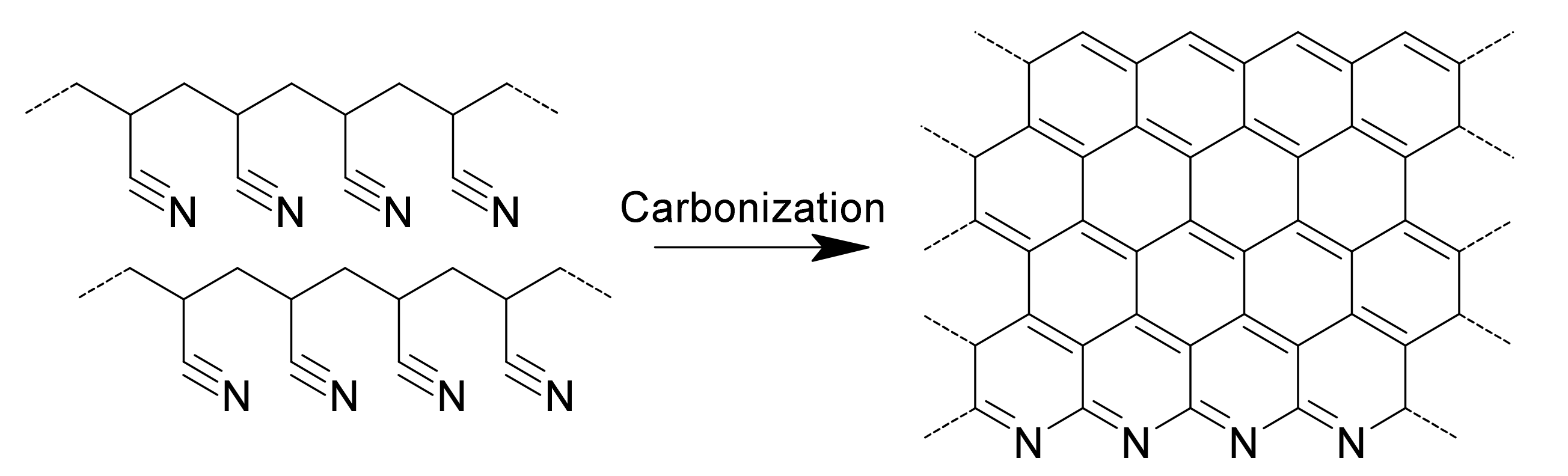
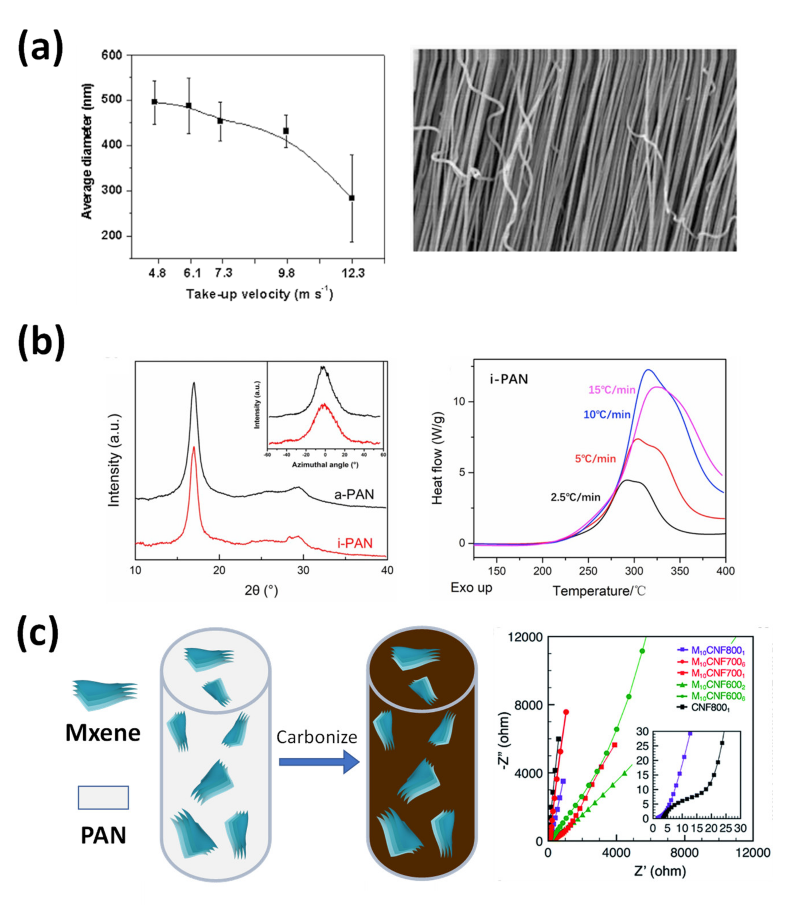
2.2.1. Polyacrylonitrile-Based Carbon Nanofibers

Polyacrylonitrile (PAN) has been used as a precursor for many carbon materials because of its unique properties including hardness, relative insolubility, and high melting temperature [35]. The high-performance properties of PAN make it an ideal candidate for electrospinning and fiber fabrication. In fact, it has been proven that the carbon fabricated from PAN has a higher melting point and carbon yield than some of the well-known precursors such as pitch or crayon [36,37]. The most commented solution used in the case of PAN is dimethylformamide (DMF). The change of PAN to carbon consists of a three-step heating process, that is, stabilization, carbonization, and orientation improvements (graphitization) [38]. During the carbonization step, an inert gas (such as argon or nitrogen) flows to protect the decomposition of the polymer chain (Figure 2) [10,11]. In most research, the stabilized PAN fiber was carbonized and retained in the carbonization process due to the limited state of laboratories. Although the process stopped at such an early stage, at around 850 °C, the final product can still give excellent outcomes in applications such as energy storage or the use of sensors [39,40].

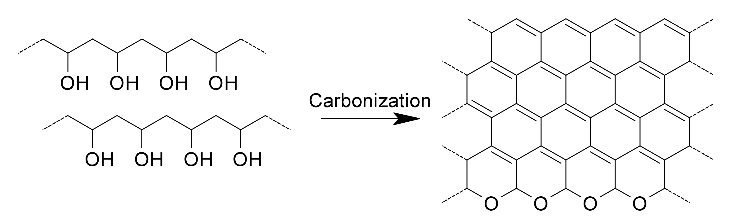
2.2.2. Polyvinyl Alcohol-Based Carbon Nanofibers

Research on polyvinyl alcohol (PVA)-based CNFs began in the 1960s [41]. PVA is a thermoplastic polymer, which is soluble in water, non-toxic, odorless, and environmentally friendly [42]. Although the mechanical stability of PVA is not as good as PAN, it is still better than that of other polymers such as polypropylene [43,44]. The excellent physical properties of PVA allow it to be made into such a small-sized fiber via electrospinning [45]. The heating process of PVA fibers includes two main stages which are stabilization and carbonization (Figure 3) [46]. Although the tensile strength of PVA fibers is weaker, the calcination temperature is much lower than PAN (Table 1). This allows PVA to be used or combined with other materials to create a composite. In addition, the carbonization of PVA does not release toxic gases such as NH3 or HCN.

2.2.3. Pitch-Based Carbon Nanofibers

Pitch, a viscoelastic polymer, can be derived from a natural source such as petroleum, coal tar, or plants. Although the other types of processors can be dissolved into a solvent to make a polymer solution for electrospinning, the pitch cannot be dissolved in any solvent and must be processed into fibers using the melt-spinning method. This requirement has limited the application of the pitch for the production of fibers as it requires a high temperature. The spinning temperature can vary between 300 and 350 °C, slightly higher than the pitch’s softening temperature [47]. Before being used in an electrospinning system, the pitch usually undergoes heat treatment to increase the molecular weight of the polymer chain [48]. Just as the softening point changes depending on the properties of the processed pitch material, the carbonization temperature is different between the studied materials. In addition, additives such as polyvinylchloride, polystyrene, cariflex, or arbocel can affect the pitch’s properties and the resulting carbonized fibers.

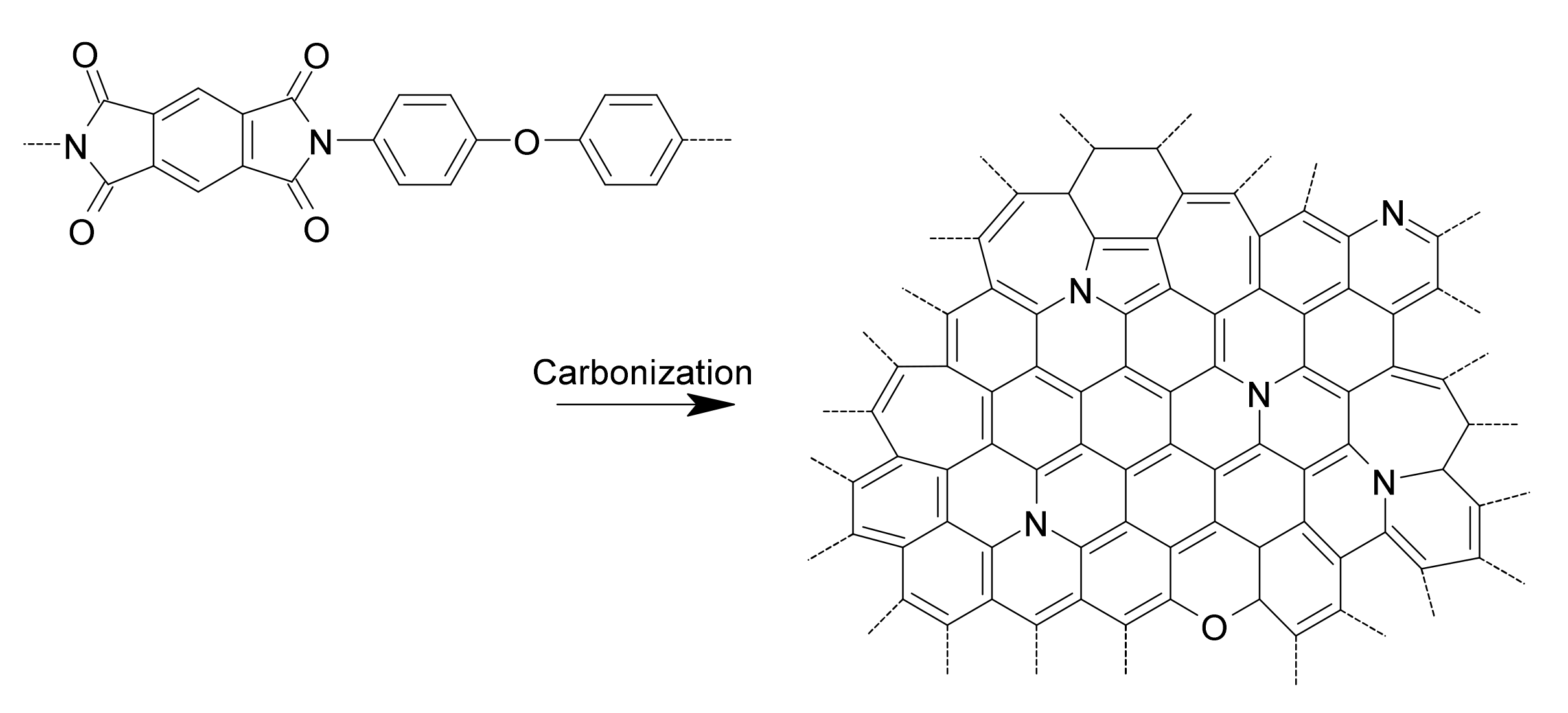
2.2.4. Polyimide-Based Carbon Nanofibers

Although polyimide (PI) has good mechanical and chemical properties, its chemical resistance makes it difficult to be dissolved in the solvents. Among many kinds of PI available on the market, PI synthesis from poly(amic acid) has been used mainly as a precursor for the carbonization as well as the graphitization process. The chemical structure of this kind of PI enables its dissolution in some organic solvents [49]. Although various steps of thermal decomposition are suggested, the product carbon contains defects in the chemical structure such as edges, pentagonal or heptagonal rings, and functional groups (Figure 4) [50]. Although defined as defects, nitrogen and the oxygen-containing functional group can increase the capacity or decrease the surface resistance between electrodes and electrolytes in an energy storage application [51].

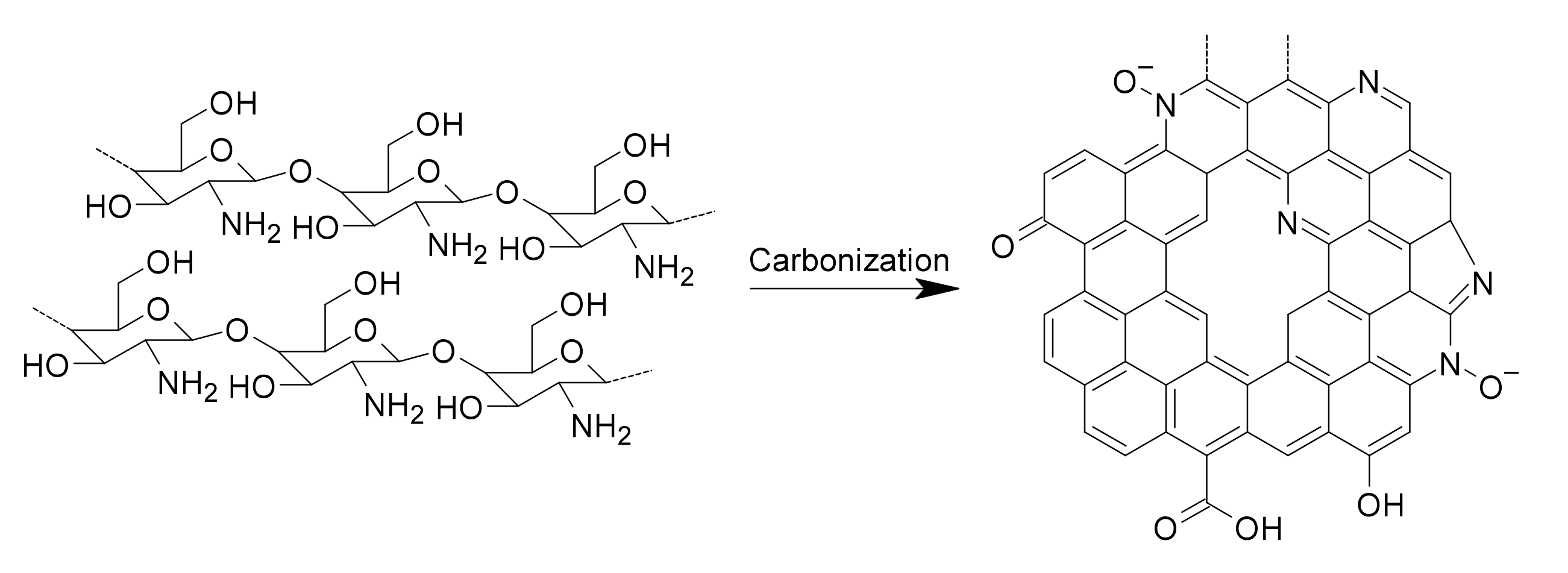
2.2.5. Carbohydrate Polymer-Based Carbon Nanofibers

Carbohydrate polymers are the most abundant type of polymers in the natural environment. They are formed from at least two mono units through glycosidic bonds [52]. Most of them contain hydrophilic groups such as hydroxyl, amino, and carboxyl groups. Since these materials have a natural origin, their use can reduce the need for a synthesized polymer, thus reducing washing and becoming an environmentally-friendly material. The most suitable solvent for carbohydrate polymers is water so there is no need for toxic solvents when used for electrospinning. The two best-known polymers are chitosan and cellulose, which showed certain flexibility with high nitrogen content [53]. Despite the advantages of their physical properties, the electrospinning fibers collapse easily, which makes them a challenge to overcome [54]. Researchers have mixed the carbohydrate with other polymers such as polyethylene glycol for a better electrospinning process and to achieve sporous fibers [55,56]. Another carbonization process that has been widely used for carbohydrate polymers is hydrothermal carbonization (Figure 5) [57]. Though the process is not usually intended for fiber materials, it still possesses great potential for further development [58].

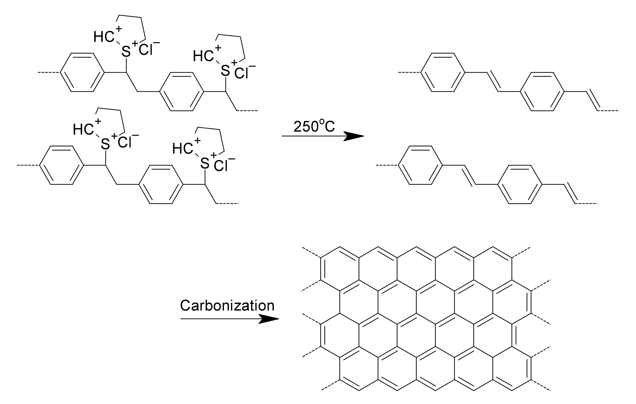
2.2.6. Poly(p-xylene tetrahydrothiophenium chloride)-Based Carbon Nanofibers

Although poly(p-phenylenevinylene) (PPV) has shown excellent electrical properties, electrospinning is incapable of manufacturing PPV fibers since the polymer is insoluble and infusible [59]. However, it is possible to spin the PPV precursor, poly(p-xylene tetrahydrothiophenium chloride) (PXTC), into nanofibers [60]. PXTC in water can be easily prepared using the reaction between alpha, alpha-dichloro-p-xylene and tetrahydrothiophene [61,62]. After carbonization, the PPV precursor can archive the graphene-like chemical structure containing mainly sp2 carbon (Figure 6) [63]. It should be noted that although PAN needs to reach temperatures of up to 2500 °C to form the graphite structure, the PPV precursors only need a temperature between 1000 °C and 1800 °C.
Table 1. Changes in carbonization temperature and gas-exposure conditions by polymer type.
PrecursorTemperature (°C)EnvironmentPurposeRef.
PAN200–300AirOxidation stabilization[38]
900–1300Argon/NitrogenCarbonization
Up to 2500Argon/NitrogenOrientation Improvement
PVA180–300AirOxidation stabilization[46]
600–1000Argon/NitrogenCarbonization
PitchBefore softening point of materialAirOxidation stabilization[64]
Up to 1200Argon/NitrogenCarbonization
PIUp to 1000Argon/NitrogenCarbonization[50]
Carbohydrate/PEO105AirOxidation stabilization[55,56]
Up to 800Argon/NitrogenCarbonization
PXTC/PPVUp to 1800Argon/NitrogenCarbonization[63]

3. Different Carbon Nanofibers Obtained by Electrospinning

The electrospinning technique can be divided into three different methods for fabricating CNFs. Depending on the application and intended use of the fiber, the user can choose a suitable technique for producing the desired carbon nanofiber.

3.1. Carbon Nanofibers from Common Electrospinning

Common electrospinning generates fibers from a simple solution containing only one kind of polymer or containing an inorganic composition. The inorganic material should not react or change shape in a high-temperature environment. Since it is affected by only one factor from the host material, it is easier to control the common electrospinning process. In addition, there is almost no effect from the inorganic material during the calcination, so the carbon fiber can retain its shape. The common electrospinning method cannot create a complicated structure, but studies are being conducted on the characteristics of CNFs depending on the changes in manufacturing conditions.
Moon et al. used electrospinning to study the unidirectional PAN yarn fibers with different alignments (Figure 7a) [65]. Then, the properties of the CNFs from the prepared polymer nanofibers were then studied. The electrospun PAN yarn nanofibers were stabilized and carbonized under many conditions, such as draw ratio, heating rate, temperature, as well as exposure time. It was concluded that 16 kV can give the best strength for CNFs with optimized condition stabilization at 200 °C and carbonization at 1350 °C. Later, Hao et al. investigated the effect of PAN isotacticity on CNF manufacturing (Figure 7b) [66]. They compared the differences in the prepared solutions, the electrospinning parameters, and the stabilization and carbonization processes. The authors used magnesium chloride to increase the percentage of isotactic in the structure of the polymer chain. The presence of a higher isotactic structure causes cyclization to occur at a lower temperature, yet it also makes electrospinning more difficult to control and reduces the carbon yield.
The CNFs that were made by electrospinning from the PAN and MXene mixing solution were investigated by Levitt et al. in order to find the optimized conditions for the electrospinning solution (Figure 7c) [67]. It has been concluded that electrospinning is possible with a concentration of MXene up to 16 wt% of the solution containing 8 wt% PAN. However, it is noted that when the MXene concentration is lower than 16 wt%, the fiber is less uniform with the MXene flakes produced from the surface. The carbonization of the electrospun nanofiber with only a small quantity of MXene decomposed at 800 °C was also investigated. Not only were the CNFs stable, but the shape of them also became more uniform at an 800 °C carbonization. In addition, the MXene-containing CNFs also exhibit a much lower resistance between the working electrode material and the electrolyte.
Though common electrospinning can manufacture CNFs easily with high uniformity, the material has a low surface area and porous volume, thus they have low working performance in the applications of carbon materials.

3.2. Carbon Nanofibers from Modified Single-Nozzle Electrospinning

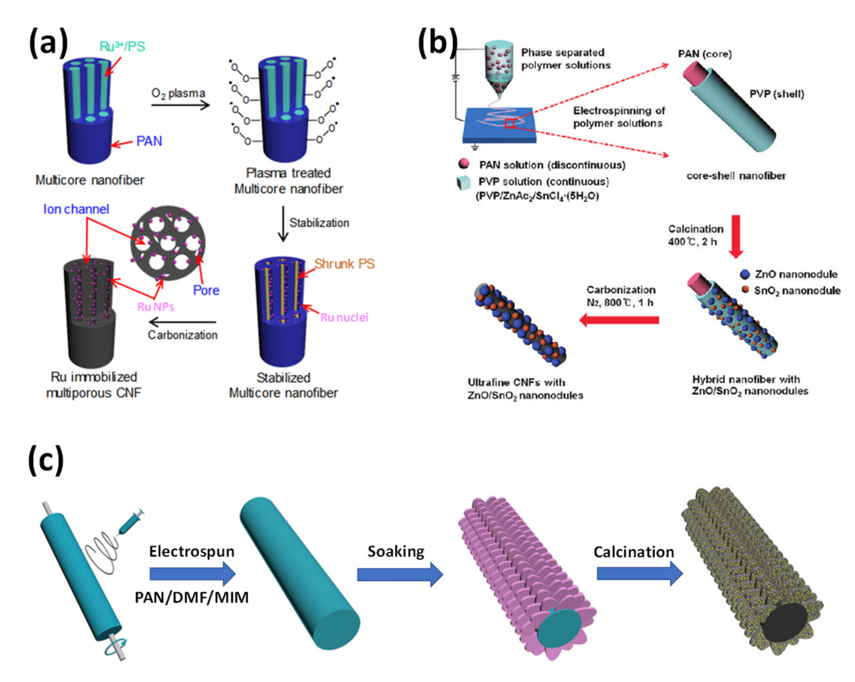
3.2.1. Porous Carbon Nanofibers

To enhance the material’s work efficiency, researchers tried to make some modifications to CNFs during or after the carbonization process. One of the most common ways is to increase the surface area of the CNFs by combining more than one type of polymer in one syringe and electrospinning using one single nozzle. Although the carbon precursor polymer turns to carbon material at high temperatures, the other polymers decompose and evaporate. Finally, the resulting fibers will contain holes and defects [68]. The physical interaction between two polymers can create many shapes that can significantly change the surface area and this, in turn, can contribute to better uses in applications [69]. However, the structure of the precursor electrospun nanofiber may become unstable during the carbonization process due to the decomposition of the material’s components. This limitation means that the fabrication of CNFs requires numerous optimizations in terms of stabilization, carbonization time, and temperature.
Kim et al. used a mixed solution of PAN and polystyrene (PS) to fabricate multiscale porous CNFs for transistor biosensors (Figure 8a) [70]. After the fabrication of the multichannel CNFs, the multichannel CNFs were steam-treated in the carbonization process to create pores on the wall [71]. The structure of multichannel CNFs helps to increase the surface area to a very impressive number of 1350 m2 g−1. Later, the multichannel CNFs were attached to the surface of a transistor as a channel for Nesfatin detection. The porous structure makes the device capable of detection even for a very low target concentration and short response time. Moreover, the device showed excellent selectivity toward other biomaterials. Other sponge-like carbon fibers were created by Yan et al. using the macro–micro dual-phase separation method (Figure 8b) [72]. The authors used poly (tetrafluoroethylene) (PTFE) nanoparticles as pore inducers, PVA as a carbon precursor, and boric acid as a crosslinker. The generated CNFs exhibited extremely high porosity, up to 80%, and a large surface area of 750 m2 g−1. Although the large surface area increases the electrode’s ability to function as a supercapacitor, the B-F-N functional group doped material provides the carbon film with high conductivity as well as a rapid transfer of matter such as CO2 or methylene blue. In addition, the solvent used for this work was water, which is an environmentally friendly solvent.
It is noticeable that surfactants can work as a separating agent that can form the shape of the precursor polymer and the carbon material [73]. The surfactant cyclodextrin (CD) is known to be good material for carbon material since it can be decomposed into carbon layers with an sp2 network. Zhang et al. used β-CD and PAN as porous CNF precursors (Figure 8c) [74]. In optimized conditions, the surface area can be increased to 156 m2 g−1. The supercapacitor not only operates at a smaller potential window compared to the device fabricated for a pure PAN precursor but also the IR drop value appears to be smaller.
Electrospinning using a combination of the precursor of carbon and secondary materials can significantly alter the physical structure of CNFs, which leads to improvements in the working capacitance of the carbon material. However, the surface tension between the ingredients can result in many difficulties for the spinning process.
Figure 8. (a) Fabrication of multiscale porous CNFs from PAN and PS using steam activation [70]. (b) Fabrication of sponge−like CNFs using PTFE particles and PVA [72]. (c) Fabrication of porous CNFs using PAN and β-CD precursors [74].
Applsci 12 06048 g008

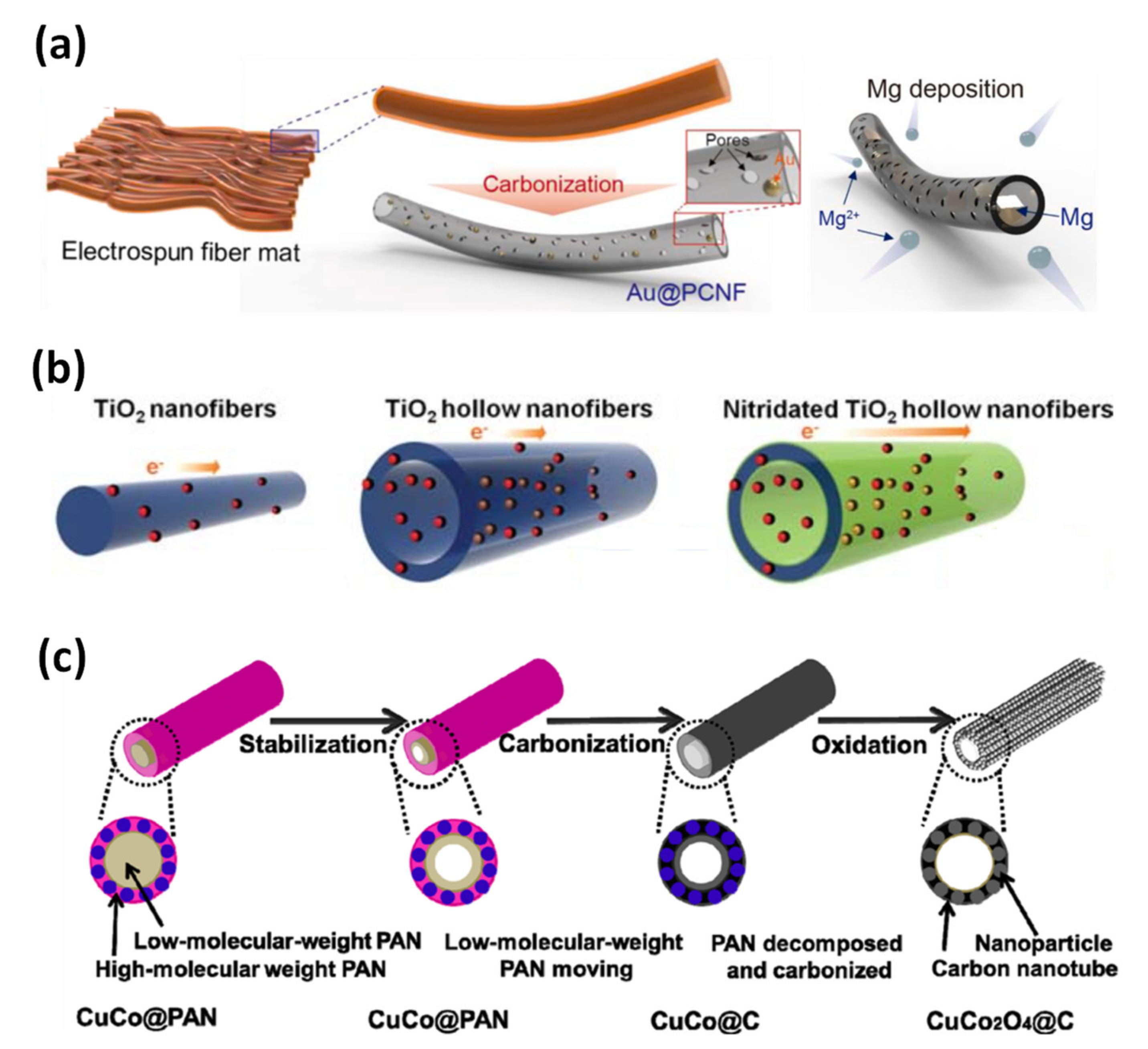
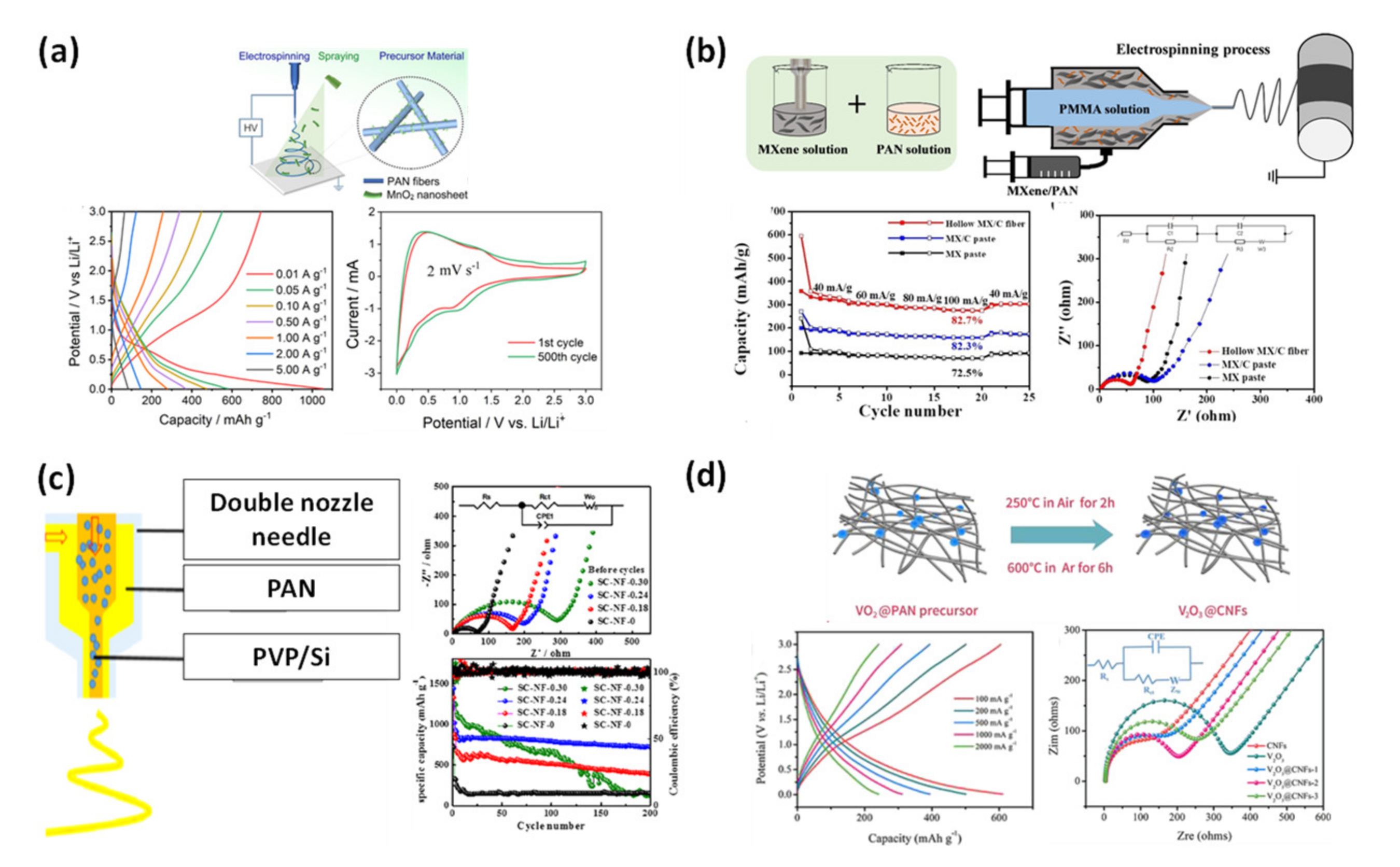
3.2.2. Metal-Oxide-Decorated Carbon Nanofibers

Another method that has been used in the application of CNFs is to combine them with metal or metal oxide for further use. Although the metal or metal oxide can act as the main working material, the CNFs play the role of the current collector [75]. Due to the large surface area, CNFs can be an ideal template for metal or metal oxide decoration.
One well-known method of decoration is to mix the metal or metal oxide precursor, which is usually in the form of a metal salt, into the polymer solution used for electrospinning. Kim et al. used multichannel CNFs as a template for ruthenium (Ru) nanoparticles decoration (Figure 9a) [76]. The electrospun nanofibers were made using an electrospinning system with a mixed solution of PAN and PS containing ruthenium chloride (RuCl3). Ru was chosen to detect dopamine because it belongs to the noble metals but is more cost-effective than gold or platinum [77,78]. Oxygen plasma was applied for the generation of the oxygen functional groups that form chemical bonds with Ru prior to the carbonization process. RuCl3 later decomposed during the PAN carbonization period and formed Ru metal particles. The Ru-containing CNFs were used as the main material for nonenzymatic field-effect transistor fabrication. As a result, the device exhibits high sensitivity that can detect the target at a low concentration of 1 fM. In addition, the device presents a long life span of up to 4 weeks.
Lee et al. fabricated CNFs covered with zinc oxide and tin oxide with the diameter of the fiber down to 100 nm (Figure 9b) [79]. During the electrospinning process, while the metal salt dispersed well in the fiber, the PAN was concentrated in the middle of the fiber as the core and the PVP formed the cover layer that acted as the shell material. Although the electrospun polymer nanofiber has a large diameter, the PAN core is only occupied in the center of the fiber. The PVP shell is decomposed completely during high-temperature calcination and leaves behind the metal-oxide particles, and the PAN, which is the central part of the fiber, is carbonized to leave the carbon fiber. The surface area of the small CNFs makes them highly sensitive to dimethyl methylphosphonate (DMMP). However, it was found that the sensitivity was the highest in the case of fibers obtained from a solution with a 1% metal salt. A higher concentration level of salt may result in a reduction in sensitivity due to the overlapping of the metal-oxide particles.
Instead of a metal or a metal-oxide precursor, an initiator can be mixed and added to the polymer solution for electrospinning. Zhang et al. mixed 2-methylimidazole (2-MeIM) with the PAN solution to use for electrospinning (Figure 9c) [80]. The electrospun nanofibers were immersed in the solution containing Zn(NO3)2·6H2O/Co(NO3)2·6H2O and 2-MeIM, where the reaction between 2-MeIM and Zn(NO3)2/Co(NO3)2 happened and formed the metal–organic framework (MOF). Later, the nanofibers came into contact with sodium molybdate (NaMoO4) to dope molybdenum to the MOF material. After carbonization, the final collected material was Co9S8-MoS2 nanocrystal embedded on the CNFs. The shape of the flakes helps to enhance the surface area as well as the electrocatalytic performance of the MOF catalyst.

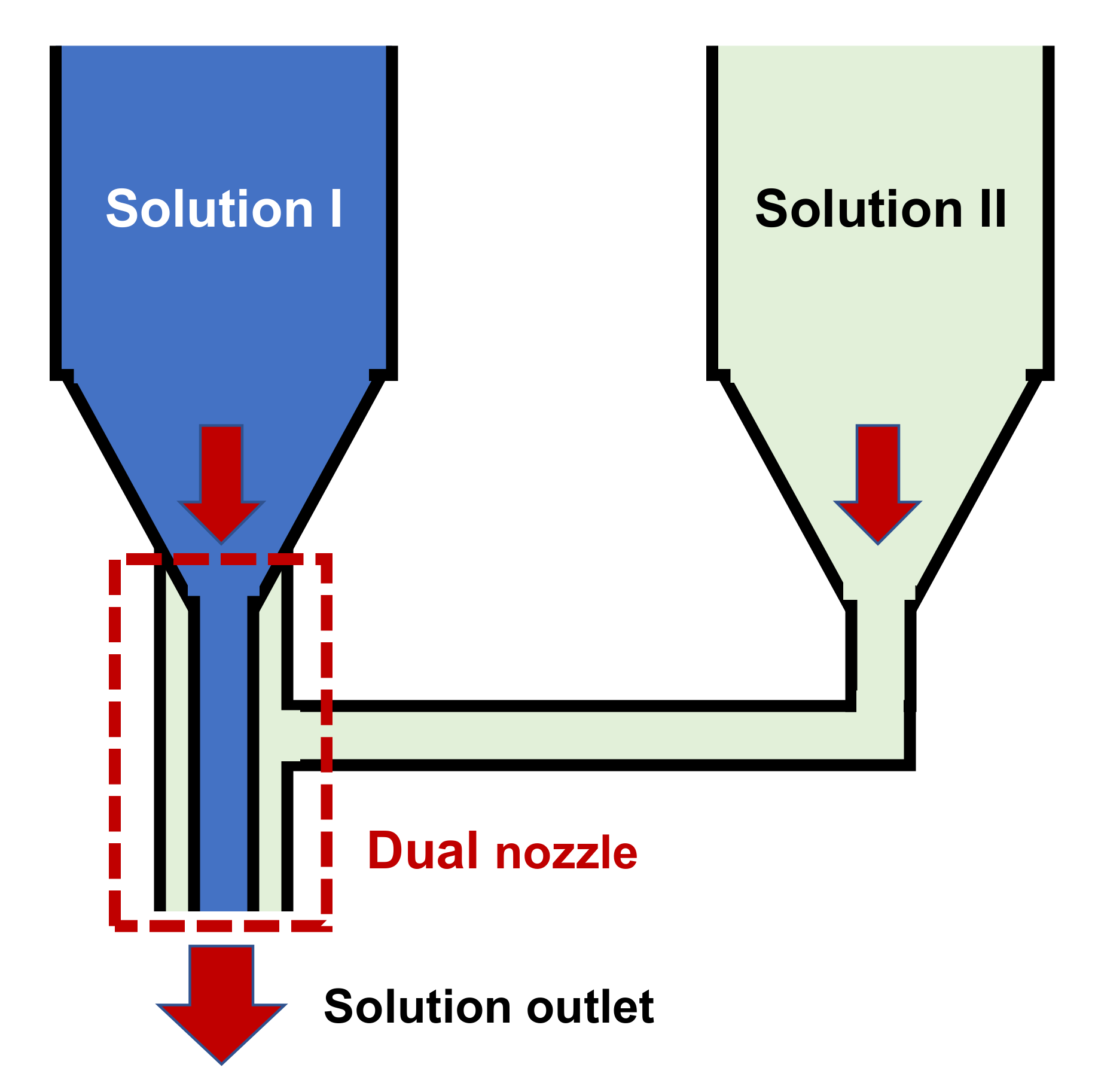
3.3. Carbon Nanofibers from Modified Dual-Nozzle Electrospinning

To manually create multilayer fibers using an electrospinning system, the engineers created the dual-nozzle needle (Figure 10). The structure of a dual nozzle includes a larger-sized cover and a smaller-sized nozzle, which will be fed with two different solutions. Using the dual nozzle, the user can easily control the position of the polymer layers in the product fibers. Despite the advantages, the use of the dual nozzle requires good control of the two solutions, from the concentration to the flow rate.
Lee et al. used the dual nozzle to fabricate porous, hollow CNFs with gold nanoparticles decorated on the inside (Figure 11a) [81]. Although the inner nozzle was fed with a poly(styrene-co-acrylonitrile) solution containing gold chloride (AgCl3), the outer nozzle was fed with a PAN solution mixed with poly(styrene-co-acrylonitrile). The dual nozzle allows the copolymer to stay inside and create a copolymer core for the electrospun nanofibers. After carbonization, the copolymer is decomposed and the gold nanoparticles remain attached to the carbon shell. The hollow fibers combined with catalytic magnesiophilic provided excellent magnesium (Mg) plating/stripping in metallic Mg battery applications.
Han et al. introduced the nitridated hollow titanium dioxide (TiO2) fibers, which act as an anode for lithium-ion batteries (Figure 11b) [82]. Although the inner nozzle was fed with heavy-mineral oil, which later decomposed during carbonization, the material for the outer nozzle was a mixture of polyvinylpyrrolidone (PVP) solution and titanium tetraisopropoxide (Ti(OCH(CH3)2)4). After the carbonization process, the oil and PVP decomposed leaving only TiO2. Due to the larger surface area, the hollow CNFs showed higher working capacity compared to nanometer-sized titanium oxide.
Wang et al. fabricated thin-wall hollow CNFs with dual-nozzle electrospinning (Figure 11c) [83]. Since low molecular-weight PAN has a lower decomposition temperature, it evaporated and the carbon layer was formed from the high molecular-weight PAN precursor. CuCo2O4 nanoparticles were also present inside the carbon layer that was made of copper nitrate and cobalt acetate mixed into the high molecular PAN solution.

4. Application of Carbon Nanofibers

4.1. Energy Storage Applications

Carbon materials have been continuously developed as electrode materials for energy storage applications [84,85,86,87,88]. There are many types of energy storage using carbon fiber electrodes including supercapacitors, batteries, fuel cells, dye-sensitized solar cells (DSSC), and catalysts [87,89].

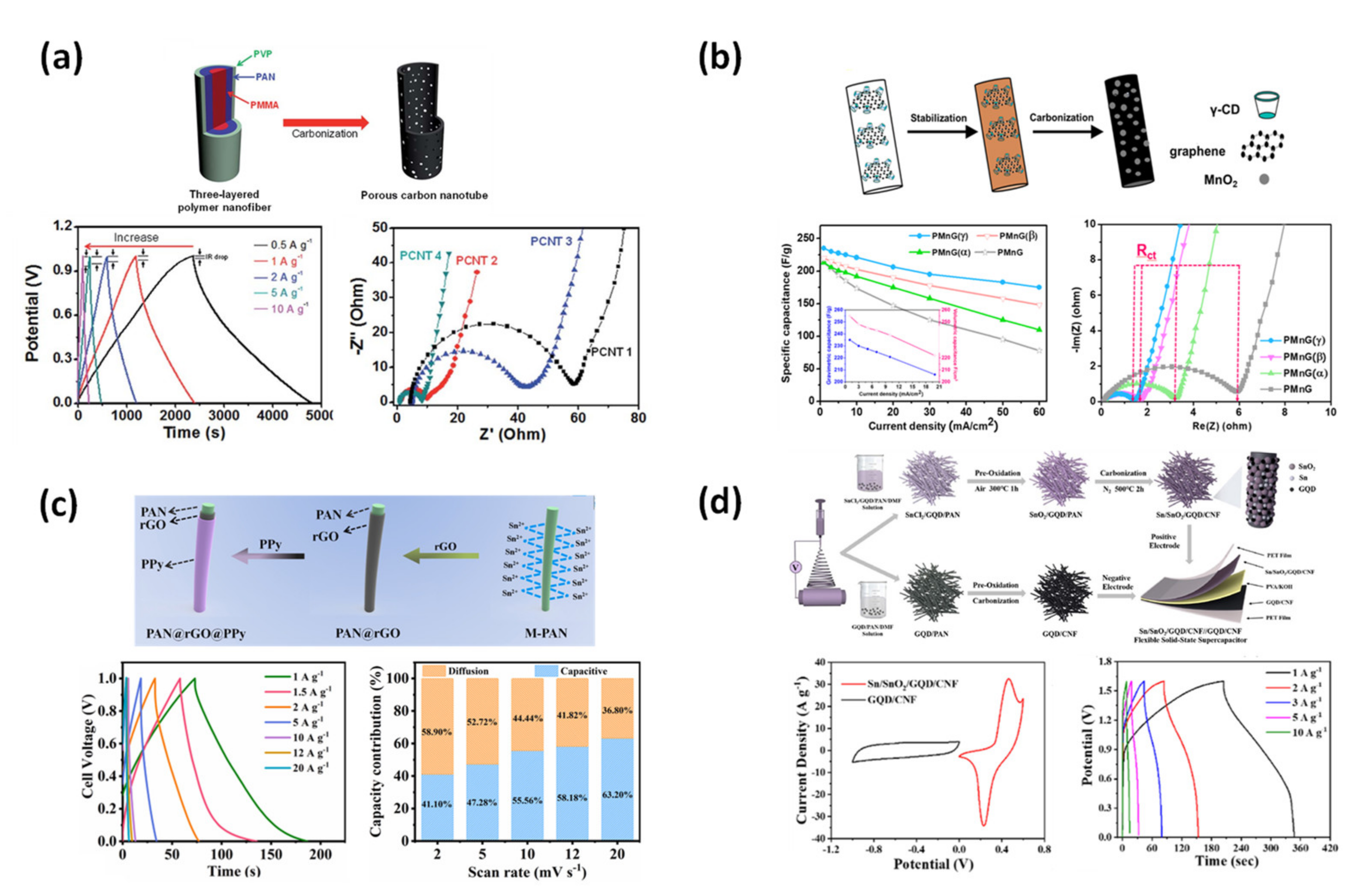
4.1.1. Supercapacitor

Lee et al. demonstrated porous, hollow CNFs that were applied to a supercapacitor (Figure 12a) [90]. Using a dual nozzle with poly(methyl methacrylate) (PMMA) solution for the inner nozzle and PAN/PVP solution for the outer nozzle. The dual-nozzle configuration formed a three-layer structure containing PMMA/PAN/PVP, respectively, and minimized the thickness of the PAN layer. Moreover, the defects of the interface between PAN and PVP created pores in the carbon structure, which further improves the volume ratio of carbon material. In addition, the authors also proved that the use of PMMA for the inner nozzle can make the PAN fibers thinner compared to the fibers that used mineral oil for the inner nozzle. With a large pore volume, the porous, hollow CNF electrode showed higher response frequencies, lower resistance with the electrolyte, and higher capacitance.
Besides increasing the surface ratio of the CNFs, one of the other common directions for enhancing the working capacity of the supercapacitor is metal-oxide decoration [91]. Yen et al. investigated CNFs containing cyclodextrin (CD) surfactant, MnO2, and graphene (Figure 12b) [92]. Surfactants such as α-CD, β-CD, and γ-CD can bind to MnCl2 and absorb on the graphene sheets, creating the MnCl2 shell structure cover around the graphene materials. The graphene material in this study improves the electrical conductivity of CNFs, as well as electrochemical performance. Though the percentage of MnO2 is very small, the capacitance of the material can be as high as 250 F g−1. The effects of different surfactants were also observed, and the results showed that α-CD can provide the largest pore volume. The surface resistance and capacity of CNFs with α-CD also have the best value.
Wang et al. introduced flexible carbon fibers using the PAN precursor for the core material (Figure 12c) [93]. The carbonization process was carried out at a low temperature of 600 °C so that the fiber could retain its flexibility. During the 600 °C carbonizations, the PAN structure was not completely carbonized, hence its electrical conductivity was low. It was noted that the diameter of the PAN fiber was only 350 nm. Then, the fibers were covered with a layer of reduced graphene oxide (rGO) using tin chloride (SnCl2) and a low concentration of hydrochloric acid [94]. The low conductivity of the carbon/PAN fiber was improved due to the high conductivity of rGO. Finally, the fibers were coated with polypyrrole (PPy) to stabilize the rGO layer as well as enhance the flexibility of the fibers. Not only did the authors operate the synthesized material as the electrodes for a coupling capacitor, but they also analyzed the contribution of diffusion and capacitive in the capacitance of the electrode. Another flexible supercapacitor based on the Sn/SnO2 anchored by a carbon skeleton was made by Li et al. (Figure 12d) [95]. The authors prepared two different electrospinning solutions for the fabrication of the two electrodes. The cathode material was made from the precursor solution containing SnCl2, graphene quantum dots (GQD), and PAN. After carbonization at 500 °C in the N2 environment, only some of the SnO2 particles were decomposed into Sn particles. The resulting carbon fibers were completely covered with GQDs, Sn, and SnO2 nanoparticles, which ensured the CNFs’ good electrical conductivity. By using the CNFs as the base for the particles, the capacity was greatly enhanced along with the stability over many cycles. The anode electrode material was made from the solution containing only PAN and GQD. Finally, a thin flexible capacitor can be fabricated with the two electrodes.
Figure 12. (a) Hollow, porous CNFs for supercapacitors from dual nozzles, with PMMA for the inner nozzle and PAN/PVP for the outer nozzle [90]. (b) Porous CNFs decorated with MnO2 from the mixed precursor of PAN, CD surfactant graphene, and graphene for the supercapacitor [92]. (c) Multilayer CNFs, rGO, and PPy for the application of the supercapacitor [93]. (d) Supercapacitor from couple electrode Sn/SnO2/GQD/CNFs versus GQD/CNFs [95].
Applsci 12 06048 g012

4.1.2. Li-Ion Battery Anode

Lithium-ion battery anode materials are one of the most popular applications of carbon-based materials. Zheng et al. studied an anode material made from PAN fibers decorated with MnO2 (Figure 13a) [96]. The MnO2 nanosheets were prepared using the wet chemical method with NaH2PO2, PVP, and KMnO4. After the electrospinning of the PAN precursor, a solution containing MnO2 was sprayed on top of the fibers. Then, the materials underwent the carbonization process, in which the MnO2 nanosheets were tightly deposited on top of the CNFs. Though the carbon anode can operate as both lithium-ion and sodium-ion storage, the application in lithium-ion batteries seems to be more promising with a much higher capacity.
Recently, MXene with its two-dimensional structure has become the ideal sheet material for electrochemical device applications. Seo et al. mixed MXene with the PAN solution for the outer layer of a dual nozzle to produce hollow CNFs (Figure 13b) [97]. By using PMMA for the inner nozzle, the authors can create a hollow structure since PMMA can decompose and evaporate very well at high-temperature carbonization. The MXene in the hollow CNF structure can yield a high capacity, four times higher than the MXene paste electrode when applied to a lithium-ion battery.
Though many studies based on CNFs decorated with metal or metal oxide have been conducted, they are usually embedded in the outer wall of the CNFs. This can limit the initial coulombic efficiency as the particles were exposed to the outside. Li et al. introduced hollow CNFs with Si nanoparticles inside the fibers (Figure 13c) [98]. Although the inner nozzle was fed with a solution containing PVP and Si nanoparticles, the outer nozzle was fed only with the PAN solution. Carbonization resulted in the hollow fiber structure that was filled with Si nanoparticles. Though the initial coulombic efficiency was improved, the fibers can break and become unstable when overloaded with particles.
In addition, the capacity of the battery can be improved by modified particles. Urchin-like vanadium-based oxide (V2O3) particles were synthesized by Liang et al. using V2O5 as a material (Figure 13d) [99]. The particles were mixed with a PAN solution as a precursor for electrospinning. Although the urchin-like particles are large in size compared with the diameter of the fibers, the collected fibers were very uniform. Multiple valence states of vanadium oxide allow the reversible lithium-ion intercalation/deintercalation. As the particles were electrospun from the same solution with PAN, the material showed good stability due to the interaction between PAN and vanadium.

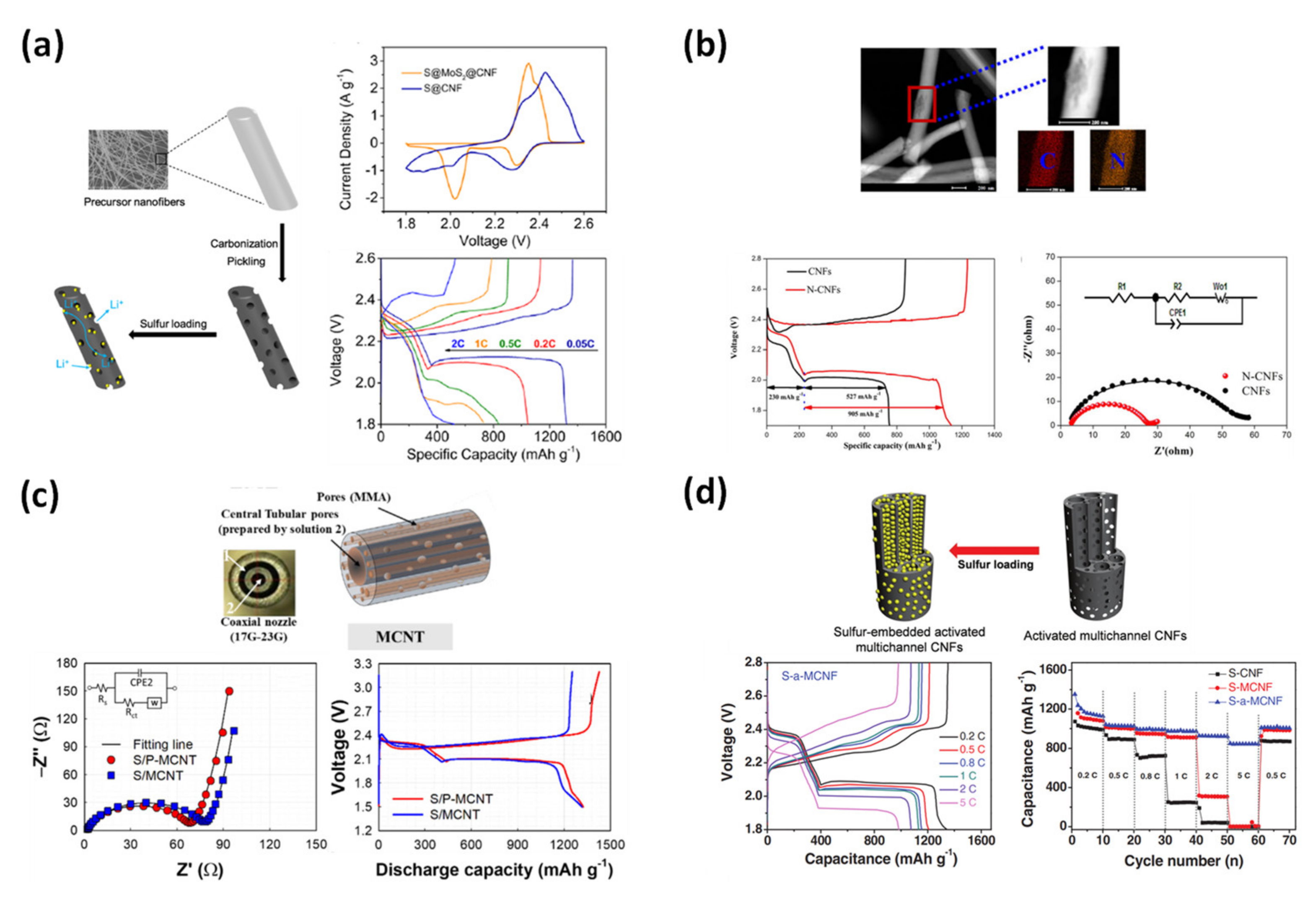
4.1.3. Lithium-Sulfur Battery

Lithium-sulfur batteries operate using electron transfers from the electrode to the electrolyte, as well as interactions between lithium ions and sulfur molecules. During charging, the lithium-ion can be oxidized into sulfur and the opposite happens in the discharge process. Improving the electrical conductivity or surface resistance of electrodes is one of the most popular ways to improve the working performance of a lithium-sulfur device [100].
Wang et al. introduced sulfur-host porous CNFs containing MoS2 that act as cathode material for a lithium-sulfur battery (Figure 14a) [101]. The precursor solution is PAN mixed with ammonium tetrathiomolybdate ((NH4)2MoS) and hydrophobic-fumed silica powder. After calcination, the collected CNFs contain both MoS2 and silica oxide (SiO2). The material is then subjected to a chemical etching process to remove SiO2 and create a porous fiber structure. The fiber precursor containing (NH4)2MoS was found to be more stable compared to the precursor without (NH4)2MoS. It can retain the fiber structure after annealing at high temperatures. The results showed that CNFs with MoS2 had a greater pore volume and capacity.
ZIF is a MOF material that contains a large number of nitrogen function groups, so the decoration of ZIF material can be a potential method of increasing the capacity of energy storage devices [102]. Yao et al. investigated a nitrogen-doped CNFs framework with ZIF-8 as the host of the functional groups (Figure 14b) [103]. Though the deposited ZIF could not enhance the surface area or the pore volume, it was able to reduce the surface resistance of the electrode. The smaller resistance allowed for smoother electron flow and an increase in material capacity.
To increase the working performance of the CNFs with surface modifications, we can increase the pore volume or the surface area of the outside wall. Wang et al. described the effect of the inner wall on the battery capacity with multichannel CNFs (Figure 14c) [104]. The authors prepared two different CNFs using PMMA, MMA, and PAN. Although one sample carried multichannel CNFs, the other was created with one big channel in the middle of the CNFs using a dual nozzle. Though the surface area of the sample fabricated with the dual nozzle is smaller, the pore volume seems to be much larger. The cycle stability has also been proven to be an advantage of the larger-sized channel. Another work based on the multichannel CNFs was conducted by Lee et al. (Figure 14d) [105]. In this study, the pore network was made by the base-treatment method using potassium hydroxide (KOH). This method created a larger pore volume compared to the pores obtained from PMMA decomposition in the study of Wang et al. [104]. In addition, KOH-treated multichannel CNFs appear to have longer cycle stability when embedded with sulfur and are operating as a lithium-sulfur battery.
Figure 14. (a) Porous CNFs embedded with sulfur applied for lithium−sulfur batteries [101]. (b) CNFs contain MOF material for nitrogen function group doping [103]. (c) Porous, hollow multichannel CNFs for lithium-sulfur battery [104]. (d) Multichannel porous CNFs using KOH-treatment process embedded with sulfur [105].
Applsci 12 06048 g014

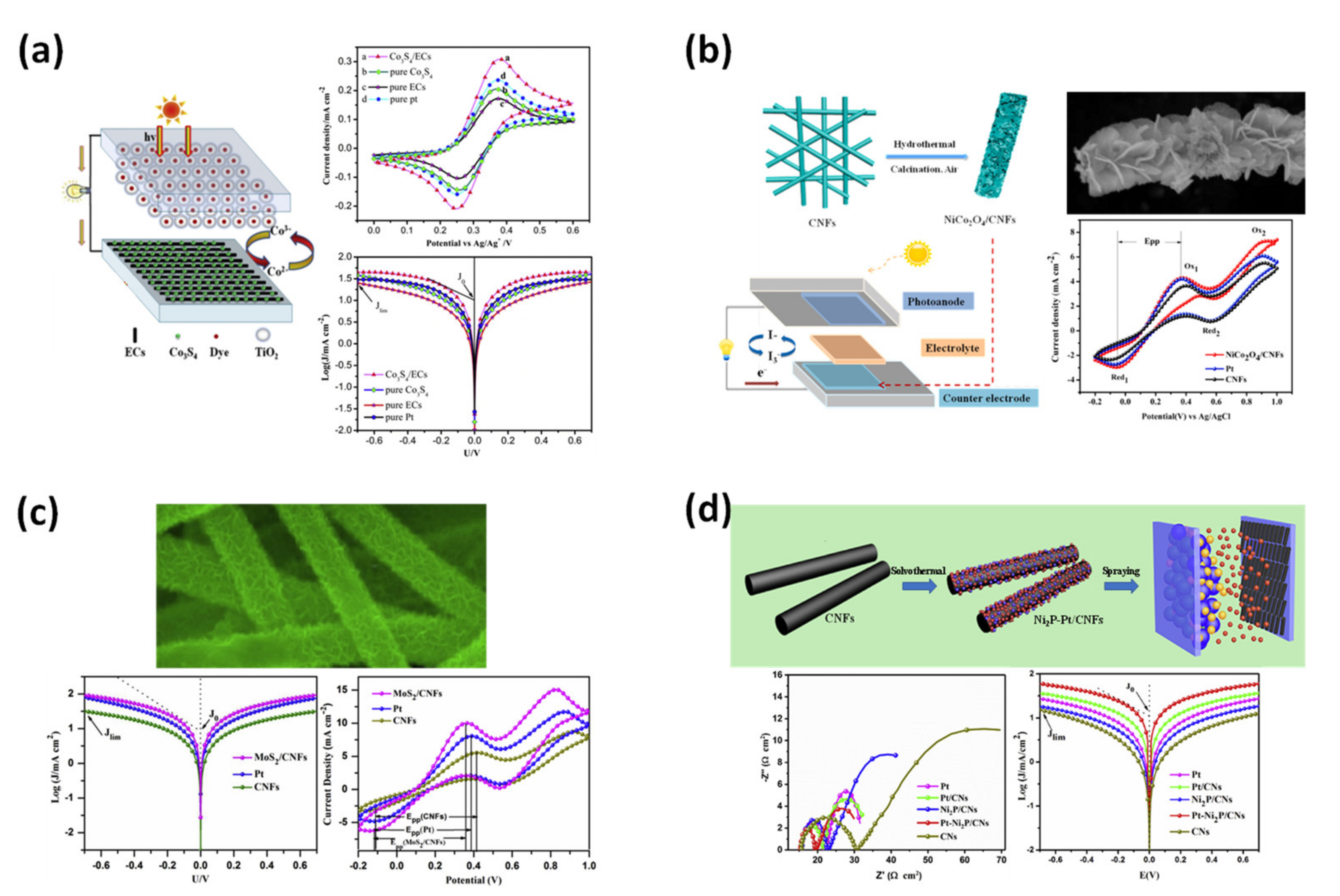
4.1.4. Dye-Sensitized Solar Cells (DSSC)
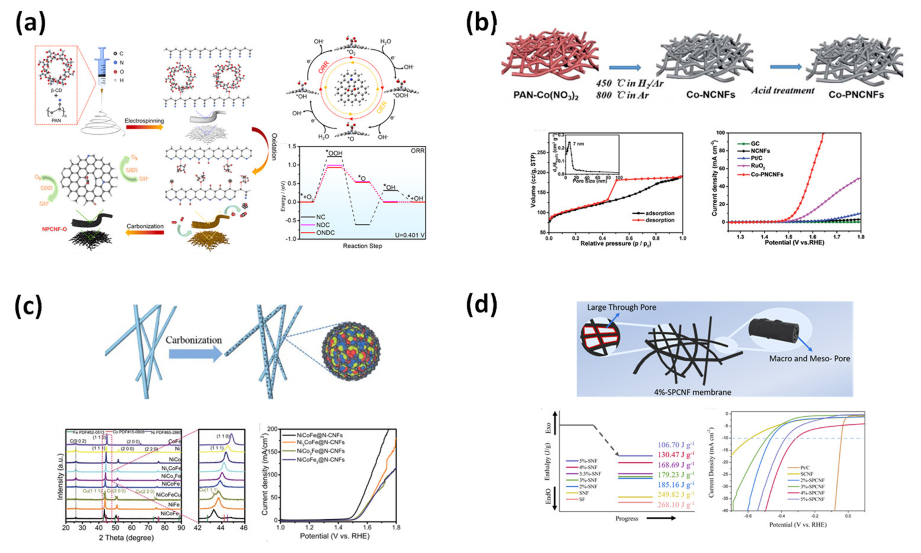
In the DSSC system, in addition to the development of dye materials in order to enhance the performance, it is also possible to consider the development of catalyst materials at the counter electrode [106]. The traditional material for the counter electrode is platinum (Pt), which is an expensive metal. Therefore, an attempt was made to replace it with a more profitable material. Carbon material that has been decorated with metal oxide appears to be a good choice for a replacement for the counter electrode [107,108].
Li et al. introduced a cathode for DSSC constructed from PAN-based CNFs embedded with Co3S4 nanoparticles (Figure 15a) [109]. The synthesized material showed good results concerning the surface area, as well as the current density compared to pure Co3S4, pure CNFs, and pure Pt. Moreover, the surface resistance between the material and the electrolyte was lower in comparison to other materials, suggesting that the material presents outstanding properties even when compared to the Pt electrode. In addition, flower-petal-shaped NiCo2O4 oxides were grown on the surface of CNFs with the hydrothermal calcination of cobalt nitrate and nickel nitrate by Li et al. (Figure 15b) [110]. The CNFs achieved by the authors had a good specific surface area with an average diameter of around 250 nm. After coating with NiCoO4, although the diameter of the material increased to 900 nm, the structure of NiCoO4 made the surface area of materials become three times larger than the bare CNFs. The coating layer also improved the conductivity and the surface resistance of the electrode. Li et al. also conducted experiments with CNFs coated with MoS2 that have the shape of a petal but with a much smaller size (Figure 15c) [111]. Though the size of the decorated fibers decreased, the MoS2 effect was less favorable than that of NiCoO4. Apart from the differences in the properties of these two metal oxides, the surface area of the CNFs did not improve much with MoS2 decoration.
Zhao et al. decorated the CNFs with a complex of Pt and Ni2P nanoparticles (Figure 15d) [112]. In the beginning, the CNFs were embedded with Ni2P nanoparticles, then the product fibers underwent another reaction to attach the Pt nanoparticles. Although Ni2P alone cannot be a good catalyst, it is a good co-catalyst to combine with Pt or Pd and contribute to the excellent DSSC performance [113,114].

4.1.5. Catalyst

Recharge energy processes such as metal-air batteries, fuel cells, and water spitting require electrocatalysis, such as the oxygen evolution reaction (OER), oxygen reduction reaction (ORR), or hydrogen evolution reaction (HER) [115,116,117]
Qiang et al. used β-CD and PAN to make precursors for the fabrication of the porous N-doped CNFs (Figure 16a) [118]. Although the β-CD surfactant had been used in numerous studies as mentioned in the previous sections, the nitrogen function group present in the structure after carbonization had not been thoroughly analyzed. The authors suggested that although β-CD could attach to the PAN chain via hydrogen bonding, it would be partially decomposed when calcined at high-temperature calcination and form the functional groups. The XPS analysis illustrated that the CNFs with β-CD have a higher percentage of graphitic-N and pyridinic-N in their structures compared to normal CNFs. The nitrogen functional groups play the role as the catalyst for the OER and ORR. In the case of the ORR, the electron-donating of graphitic is the active side, and the electron-withdrawing of pyridinic-N is the active side of the OER [119,120]. In addition, the β-CD-containing CNFs also have a large number of oxygen functional groups that will react to operate the system. The authors also presented the theory of operational mechanisms. Though the surfactant did not show any effects on the BET, the working performance was improved. In applications, the rechargeable zinc-air batteries that used the developed material also have outstanding stability over time.
Zhao et al. tried to decorate cobalt nanoparticles on CNFs made from a PAN precursor (Figure 16b) [121]. After fabrication, the activities of the cobalt nanoparticles were investigated throughout. Although not an ideal material to be used in the ORR system, it can act as an OER catalyst better than the traditional Pt/C electrode. Later, Cao et al. fabricated CNFs containing metal alloy particles of nickel, cobalt, and iron (Figure 16c) [122]. The carbon source used in the work is PVP; after a longtime stabilization, PVP can turn into carbon at temperatures up to 800 °C [123,124]. PVP requires a lower carbonization temperature and the carbon structure can be naturally doped with nitrogen. On the other hand, the mechanical properties of the produced CNFs are not good, and the fibers can be easily broken during the carbonization process. The combination of the three metals shows further improvements in the catalyst activities. It is noted that when activated as an ORR catalyst, the current density and halfwave potential of the synthesized material can be compared with the counter Pt/C electrode. Yet, when activated as a catalyst for an OER, the decorated material can work much better compared to Pt/C or CNFs embedded with other combinations of the used ingredients. Hence, it can be said that carbon-based materials have the potential to replace Pt materials, which are known for their expensive costs. Furthermore, the authors investigated the effects of different ratios of the ingredients on the working performance of the catalyst. It seems that the alloy that has Ni, Co, and Fe with a ratio of 1:1:1 has the greatest catalytic properties.
Inspired by the rich-in-nitrogen functional groups of fibroin fibers, He et al. used the processed fibroin for electrospinning to make CNFs (Figure 16d) [125]. After a complicated process to remove the impurities, the regenerated silk was dissolved in a solution containing potassium chloride (KCl). It is said that the KCl not only reduces the diameter of the electrospun nanofiber but also affects the crystalline structure of the polymer composite. Although KCl can produce a porous structure for the CNFs, the high concentration of KCl (higher than 5%) cannot create plentiful pores. Among the samples, the one containing 4% of KCl exhibits the highest catalytic activity in HER application in both acidic and alkaline environments.
Figure 16. (a) Effects of β-CD surfactant on the catalytic activation of porous CNFs in ORR/OER fuel cell [118]. (b) CNFs decorated with Co nanoparticles for OER catalyst material [121]. (c) NiCoFe metal alloy for catalyst material of both ORR and OER systems [122]. (d) CNF fibers from fibroin of silk for catalyst material [125].
Applsci 12 06048 g016

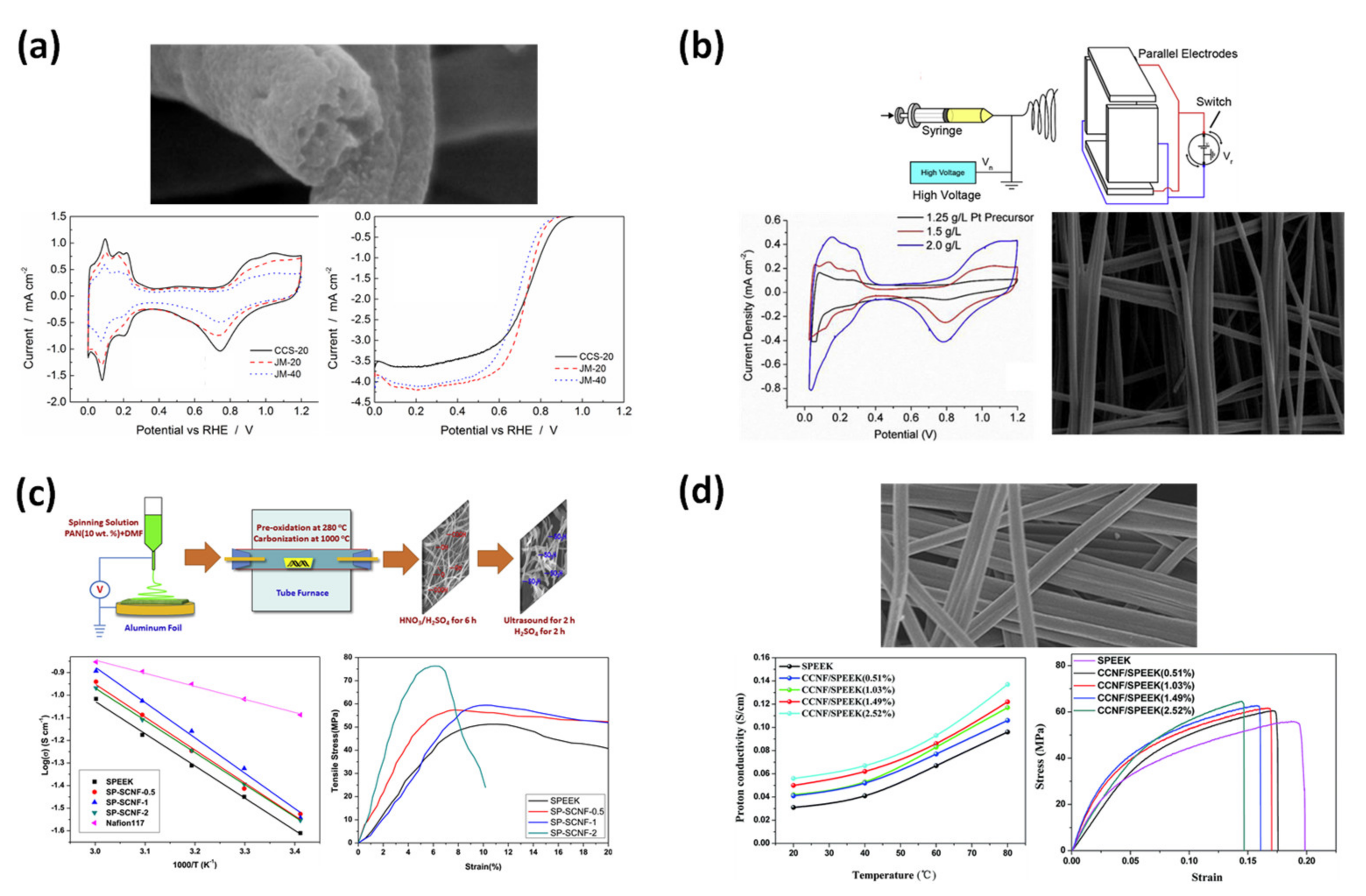
4.1.6. Membrane Electrode Assembly for Fuel Cells

In the fuel cell system, in addition to the electrode, attention is paid to the development of the membrane electrode assembly (MEA). Song et al. developed an ion membrane based on multichannel CNFs (Figure 17a) [126]. Using a precursor from PAN mixed with PMMA, they electrospun the material into fibers, stabilized and carbonized at up to 1400 °C. The higher the carbonizing temperature, the stronger the G peak in the Raman spectra, indicating the presence of the graphitized structure. Furthermore, the multichannel CNFs were decorated with Pt/C catalyst nanoparticles, turning them into an MEA. Not only is the mass transport resistance of the membrane low, but it also facilitates the draining of water from the catalyst. Chan et al. modified the electrospinning collector into parallel electrodes to arrange the electrospun fibers into orthogonally aligned nanofibers (Figure 17b) [127]. The well-aligned fibers formed many small channels which allowed the ions to penetrate easily. After carbonization, the aligned CNFs were decorated with Pt using wet chemistry plating and sputter coating. The membrane structure also helps the plating of the Pt catalyst to occur uniformly.
Di et al. used a composite of CNFs from PAN and synthesized a sulfonated poly(ether ether ketone) (SPEEK) (Figure 17c) [128]. SPEEK is a low-cost ion transfer material with excellent mechanical and chemical properties. However, since PEEK with high sulfonate content accommodates too much water, it can swell in an aqueous environment. On the other hand, a low concentration of sulfonate causes low conductivity, thus the authors mixed it with CNFs to obtain an MEA layer. The MEA showed good results in the physical strength of the tensile test and ion conductivity. Liu et al. prepared the MEA by mixing the acid-sulfuric-treated CNFs from the PAN carbonization (Figure 17d) [129]. After carbonization, the CNFs emerged in the mixture of sulfuric acid and nitric acid to attach functional groups on the surface of CNFs. The fibers were then mixed with the synthesized SPEEK and cast on a glass substrate. With the hydrogen bond formed between the acid groups on the CNFs and SPEEK, the thickness of the membrane was reported to be around 40 μm. The composite membrane appears to have high tensile strength with break points at 75 MPa stress and 7% strain. The proton conductivity of the introduced material can be comparable to Nafion.
Figure 17. (a) MEA constructed of multichannel fibers, carbonization at high temperature [126]. (b) Orthogonally aligned CNFs for MEA in fuel cells [127]. (c) MEA from the composite of CNFs and SPEEK [128]. (d) MEA from the acid−treated CNFs and SPEEK [129].
Applsci 12 06048 g017

4.2. Sensor Applications

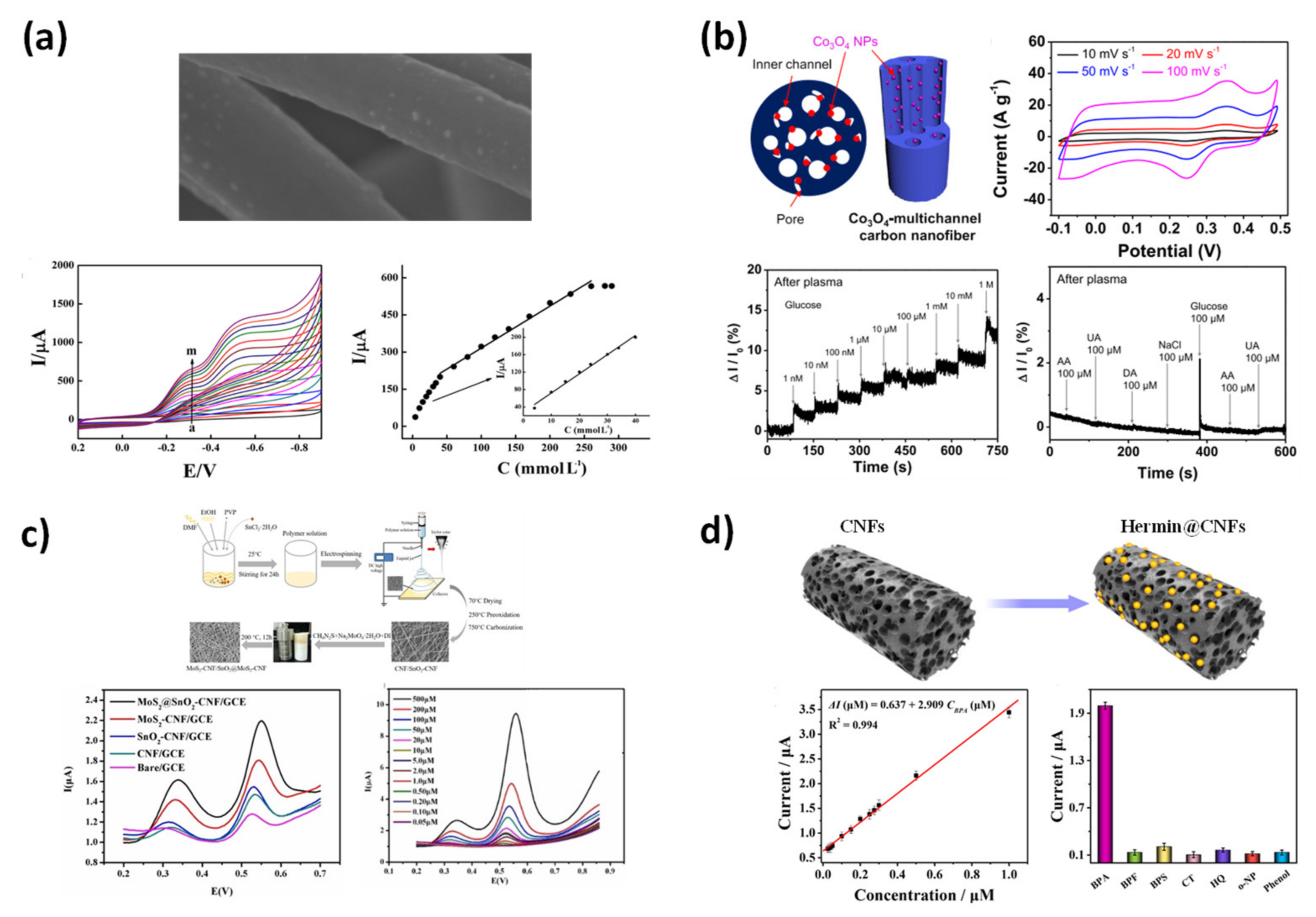
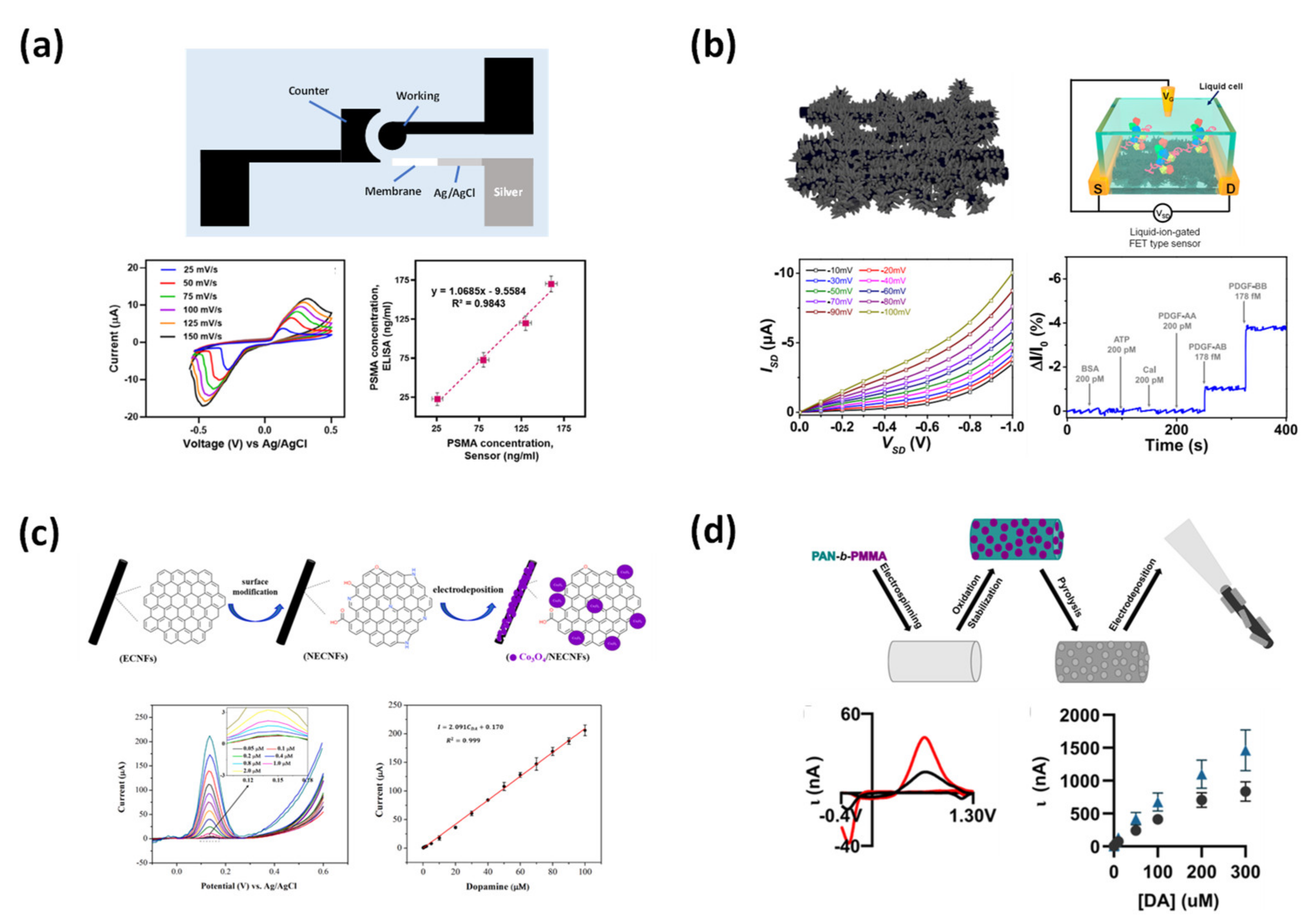
4.2.1. Electrochemical Sensor

Electrochemical sensing is a popular application of carbon material. For different targets, the researchers used different measurement techniques such as voltammetry (cyclic voltammetry, differential-pulse voltammetry, square-wave voltammetry, etc.), amperometry, and potentiometry, conductivity, and impedance changes [130,131].
Xie et al. studied the ability of Co3O4 (combination of Co2+ and Co3+) in the detection of trichloroacetic acid (TCA), KBrO3, and NaNO2 with CV measurements (Figure 18a) [132]. Although the material proved to be capable of detecting a variety of targets, it did not exhibit high sensitivity. The low surface area of simple CNFs may have limited their ability to detect a low concentration of the target chemical. The CNFs decorated with cobalt oxide nanoparticles still have high potential in the application of an electrochemical sensor for many yet-to-be-discovered targets. Kim et al. developed a multichannel CNF decorated with Co3O4 that could be used as a material for both a supercapacitor and an electrochemical sensor (Figure 18b) [133]. In the presence of glucose, Co3O4 can be converted into CoOOH. When applying 0.55 V, the redox peak increases with the addition of more condensed glucose. The authors used the potentiometric measurement method to detect different concentrations of glucose in a solution. Due to the excellent pore volume of the multichannel carbon structure, the material exhibited a wild detection range from 1 nM up to 1 M.
Hu et al. combined the decoration of SnO2 and the modification of MoS2 on the carbon structure by using a glassy carbon electrode for the detection of phenacetin and indomethacin (Figure 18c) [134]. It was proven that the SnO2 and MoS2 can provide their own contributions to the outstanding performance of the CNFs. The present of MoS2 can reduce the resistance of the carbon electrode with the electrolyte solution and it can also enhance the current peak signal. Although the detection range can reach a limit from 50 nM up to 0.5 M for indomethacin, the detection limit of phenacetin seems to be greater (from 50 nM to 7.2 M). Since the differential pulse voltammetry measurement was used for detection, the CNFs can detect the concentration very clearly [135].
Zhang et al. used Hermin to embed active iron ions (Fe3+) on the surface of CNFs from the PAN precursor (Figure 18d) [136]. By controlling the voltage applied in the electrospinning process (12, 15, and 35 kV), the effects of the diameter of fibers were also investigated. The CNFs made from fibers electrospun with 15 kV exhibited the largest surface area as well as mesopore ratio, so they also showed the highest capacitive currents. The fiber was continued to be tested for bisphenol A (BPA) detection. The ultra-sensitive linear range is from 3 mM up to 1 μM with outstanding selectivity. In addition, the stability and reproducibility of the material also produce remarkable results.
Figure 18. (a) Trichloroacetic acid (TCA), KBrO3, and NaNO2 using Co3O4 embedded CNFs [132]. (b) Multichannel CNFs decorated with Co3O4 as a glucose sensor [133]. (c) CNFs modified using MoS2 and embedded with SnO2 for phenacetin/indomethacin detection [134]. (d) Porous CNFs with Fe3+ for the detection of BPA [136].
Applsci 12 06048 g018

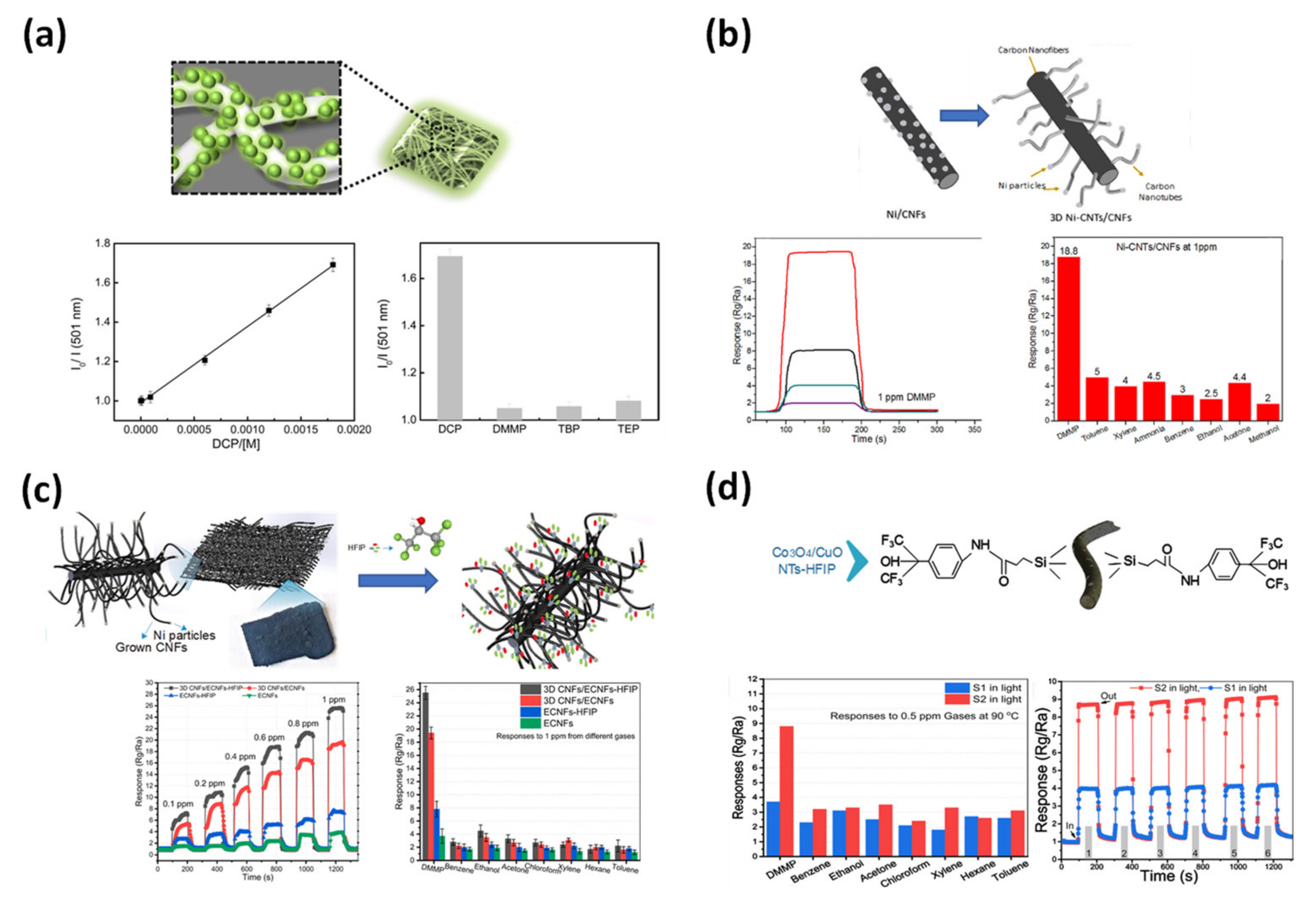
4.2.2. Warfare Agent Chemical Sensors

Warfare nerve agents are toxic organophosphorus compounds that were developed during World War II, including G, V, and A types. Due to the quick and clear visible response to the presence of the detecting target, optical measurements have been widely used in research and real-life applications [137]. Jo et al. developed an organic–inorganic hybrid material from conjugated polymer dots, silica, and PVA (Figure 19a) [138]. The dots were attached to the amine function group on half-carbonized PVA-silica NFs. The authors suggested an interesting interaction between the components of the fibers that helps to enhance the fluorescence intensity in the measurements.
Although the spectroscopy-detecting method has been used for a long time, it still has many limitations caused by its low selectivity and cannot be reused. The use of electrical analysis can overcome these limitations and increase its potential in the field of warfare-agent detection [139]. Alaki et al. studied the fabrication of cactus-like CNFs for the detection of dimethyl methylphosphonate (DMMP) (Figure 19b) [140]. The CNFs were embedded with Ni nanoparticles as a seed for the development of smaller-sized carbon fibers from cellulose acetate through the chemical vapor deposition method. It is noted that though the Ni nanoparticles themselves can enhance the signal from the interaction with DMMP, the structure of the cactus-like CNFs was able to significantly improve the surface area and the response signal. In addition, the developed material also has high selectivity towards DMMP. Alaki et al. later introduced a study based on cactus-like CNFs but with the modification of the hexafluoroisopropanol (HFIP) function group (Figure 19c) [141]. The cactus CNFs were doped with HFIP using carboxyl groups formed on the carbon surface by treatment with a strong acid. It is mentioned that HFIP can decrease the response and recovery time of material when there is a change in DMMP in the environment, even with a low concentration of 0.1 ppm.
Using a PAN/PVP solution mixed with CuCl2 and CoCl2 as the precursor of electrospinning, Alaki et al. presented CNF composites containing CuO and Co3O4 to study the effects of HFIP on the working performance of the device (Figure 19d) [142]. The fibers were treated with a silane coupling agent to attach carboxyl function groups, which were later used as a bridge to embed a modified HFIP. It was shown that with only a metal-oxide composite, even though the material can detect DMMP, the selectivity is low since the material also responds to other chemicals such as benzene, ethanol, or acetone. The presence of HFIP can enhance the response resistance and response/recovery time. Moreover, it seems that HFIP only enhances the response to DMMP, so it gives the material selectivity.
Figure 19. (a) CNFs carry quantum dots for diethyl chlorophosphate fluorescent detection [138]. (b) Cactus-like CNFs with Ni nanoparticles for detection of DMMP [140]. (c) Cactus CNFs modified with HFIP for DMMP sensor [141]. (d) CNFs/CuO/Co3O4 with silicone coupling agent and HFIP for DMMP detection [142].
Applsci 12 06048 g019

4.2.3. Biosensor

A biosensor is a type of sensor that can detect harmful bio elements, which can affect the health of the studied target. One of the most popular detection methods is to use a type of antibody or an aptamer as the key for the sensing mechanism, which provides the sensor with excellent selectivity and high sensitivity. To attach the antibody or aptamer to the material surface, carboxyl or nitrile functional groups are required in the structure of the material. Rezaei et al. successfully functionalized the CNFs by stirring in a 30% nitric acid solution (Figure 20a) [143]. The results suggested that the treatment did not affect the diameter of the CNFs. When a detecting target binds to the antibody, it changes the surface resistance between the material and the electrolyte, which can be measured by electrochemical impedance spectroscopy (EIS). The device can detect PSMA and ELISA with detection limits of 22.1 pg mL−1 and 9.5 ng mL−1, respectively.
Lee et al. used an attached aptamer for the detection of the platelet-induced growth factor (PDGF-BB) (Figure 20b) [144]. By introducing copper (Cu) into carbon fiber, the extra carbon layer could be grown on the Cu surface through chemical vapor deposition (CVD) with methane gas as a carbon source. After the Cu etching process, the CNFs had a 3D nanoweb structure, which significantly improved the surface area of the carbon material. Finally, the material was fabricated into a field-effect transistor with the screen printing of silver paste. The detection was carried out with a voltammetry measurement, and the device could operate with a detection limit of 1.78 fM with high selectivity. Moreover, the transistor can distinguish between the three types of PDGF; the BB type showed the largest change in current, the response to the presence of the AB type was smaller, and the AA type showed no response.
Yin et al. used Co3O4 and DPV measurements to detect the concentration of dopamine (DA) (Figure 20c) [145]. Before the electrodeposition of Co3O4, the CNFs were doped with a nitrogen function group using an 8 M nitric acid solution. Although the acid treatment played a role in reducing the material surface resistance, the presence of Co3O4 improved the electrocatalysis of the carbon electrode. The DPV data also showed that the material can distinguish DA from ascorbic acid and uric acid, which have similar redox properties. The peak of DA in the DPV curve appears to be much higher than the others even though the concentration is lower. The limit of detection from the material appears to be 9 nM with a wild dynamic linear range, indicating the CNFs excellent sensitivity and fast-charge transport.
Ostertag studied the effects of electrodeposition in the process of electrode preparation on the performant of the carbon electrode in the detection of DA (Figure 20d) [146]. The authors used electrodeposition to attach the porous CNFs to a bare carbon electrode. While keeping the waveform parameter unchanged, the change in the deposition time can affect the oxidation peak current. A specific deposition time (30 s) showed significant results compared to longer deposition times. The prepared electrode has outstanding sensitivity and selectivity and can be reused up to 25 times.

5. Conclusions and Outlook

In this paper, we introduce a manufacturing method for CNFs with various generated structures based on electrospinning and their application to sensors and energy storage materials. First, it was confirmed that not only the surface area and the pore volume of the CNFs are improved, but also the final morphology can be altered by using a combination of different types of nozzles and polymer precursors. In addition, the production of composite CNFs into which an inorganic material is introduced was proposed using a combination with various metal oxide precursors. As described above, it was confirmed that it has an excellent performance by applying CNFs with different structures and combinations as an electrode material for sensors and as an energy storage material. In conclusion, the electrospinning method proposed in this paper is an excellent method to produce CNFs with excellent performance in a large capacity.

Author Contributions

The manuscript was written by T.D.N. and was edited by J.S.L. All authors have read and agreed to the published version of the manuscript.

Funding

This research received no external funding.

Institutional Review Board Statement

Not applicable.

Informed Consent Statement

Not applicable.

Data Availability Statement

Not applicable.

Acknowledgments

This work was supported by the National Research Foundation of Korea (NRF) grant funded by the Korean government (no. 2020R1A4A407983711).

Conflicts of Interest

The authors declare no conflict of interest.

References

  1. Allen, M.J.; Tung, V.C.; Kaner, R.B. Honeycomb Carbon: A Review of Graphene. Chem. Rev. 2009, 110, 132–145. [Google Scholar] [CrossRef] [PubMed]
  2. Wang, D.-Y.; Wei, C.-Y.; Lin, M.-C.; Pan, C.-J.; Chou, H.-L.; Chen, H.-A.; Gong, M.; Wu, Y.; Yuan, C.; Angell, M.; et al. Advanced rechargeable aluminium ion battery with a high-quality natural graphite cathode. Nat. Commun. 2017, 8, 14283. [Google Scholar] [CrossRef] [PubMed]
  3. Muldoon, J.; Bucur, C.B.; Gregory, T. Quest for nonaqueous multivalent secondary batteries: Magnesium and beyond. Chem. Rev. 2014, 114, 11683–11720. [Google Scholar] [CrossRef] [PubMed]
  4. Zhang, X.; Tang, Y.; Zhang, F.; Lee, C.-S. A Novel Aluminum-Graphite Dual-Ion Battery. Adv. Energy Mater. 2016, 6, 1502588. [Google Scholar] [CrossRef] [Green Version]
  5. Silva, R.; Silva, S. Properties of Amorphous Carbon; The Institution of Engineering and Technology: London, UK, 2003. [Google Scholar]
  6. Beeman, D.; Silverman, J.; Lynds, R.; Anderson, M.R. Modeling studies of amorphous carbon. Phys. Rev. B 1984, 30, 870–875. [Google Scholar] [CrossRef]
  7. Chu, P.K.; Li, L. Characterization of amorphous and nanocrystalline carbon films. Mater. Chem. Phys. 2006, 96, 253–277. [Google Scholar] [CrossRef]
  8. Fitzer, E.; Frohs, W.; Heine, M. Optimization of stabilization and carbonization treatment of PAN fibres and structural characterization of the resulting carbon fibres. Carbon 1986, 24, 387–395. [Google Scholar] [CrossRef]
  9. Shen, C.; Sun, Y.; Yao, W.; Lu, Y. Facile synthesis of polypyrrole nanospheres and their carbonized products for potential application in high-performance supercapacitors. Polymer 2014, 55, 2817–2824. [Google Scholar] [CrossRef]
  10. Föllmer, M.; Jestin, S.; Neri, W.; Vo, V.S.; Derré, A.; Mercader, C.; Poulin, P. Wet-Spinning and Carbonization of Lignin-Polyvinyl Alcohol Precursor Fibers. Adv. Sustain. Syst. 2019, 3, e201900082. [Google Scholar] [CrossRef]
  11. Wang, Z.L.; Kang, Z.C. Pairing of Pentagonal and Heptagonal Carbon Rings in the Growth of Nanosize Carbon Spheres Synthesized by a Mixed-Valent Oxide-Catalytic Carbonization Process. J. Phys. Chem. 1996, 100, 17725–17731. [Google Scholar] [CrossRef] [Green Version]
  12. Zhong, C.; Chen, Y.; Yu, Z.-M.; Xie, Y.; Wang, H.; Yang, S.A.; Zhang, S. Three-dimensional Pentagon Carbon with a genesis of emergent fermions. Nat. Commun. 2017, 8, 15641. [Google Scholar] [CrossRef] [PubMed]
  13. Zhao, C.-X.; Yang, Y.-Q.; Niu, C.-Y.; Wang, J.-Q.; Jia, Y. C-57 carbon: A two-dimensional metallic carbon allotrope with pentagonal and heptagonal rings. Comput. Mater. Sci. 2019, 160, 115–119. [Google Scholar] [CrossRef]
  14. Li, S.; Chen, C.; Fu, K.; White, R.; Zhao, C.; Bradford, P.D.; Zhang, X. Nanosized Ge@CNF, Ge@C@CNF and Ge@CNF@C composites via chemical vapour deposition method for use in advanced lithium-ion batteries. J. Power Sources 2014, 253, 366–372. [Google Scholar] [CrossRef]
  15. Liu, Y.; Luo, J.; Helleu, C.; Behr, M.; Ba, H.; Romero, T.; Hébraud, A.; Schlatter, G.; Ersen, O.; Su, D.S.; et al. Hierarchical porous carbon fibers/carbon nanofibers monolith from electrospinning/CVD processes as a high effective surface area support platform. J. Mater. Chem. A 2016, 5, 2151–2162. [Google Scholar] [CrossRef]
  16. Li, M.; Li, N.; Shao, W.; Zhou, C. Synthesis of carbon nanofibers by CVD as a catalyst support material using atomically ordered Ni3C nanoparticles. Nanotechnology 2016, 27, 505706. [Google Scholar] [CrossRef]
  17. Barhoum, A.; Pal, K.; Rahier, H.; Uludag, H.; Kim, I.S.; Bechelany, M. Nanofibers as new-generation materials: From spinning and nano-spinning fabrication techniques to emerging applications. Appl. Mater. Today 2019, 17, 1–35. [Google Scholar] [CrossRef]
  18. Zuo, X.; Xu, P.; Zhang, C.; Li, M.; Jiang, X.; Yue, X. Porous magnetic carbon nanofibers (P-CNF/Fe) for low-frequency electromagnetic wave absorption synthesized by electrospinning. Ceram. Int. 2018, 45, 4474–4481. [Google Scholar] [CrossRef]
  19. Xu, Y.; Yuan, T.; Bian, Z.; Sun, H.; Pang, Y.; Peng, C.; Yang, J.; Zheng, S. Electrospun flexible Si/C@CNF nonwoven anode for high capacity and durable lithium-ion battery. Compos. Commun. 2018, 11, 1–5. [Google Scholar] [CrossRef]
  20. Guan, J.; Chen, W.; Fang, Y.; Wang, L.; Fu, Y.; Guo, B.; Zhang, M. Electrospinning derivative fabrication of sandwich-structured CNF/Co3S4/MoS2 as self-supported electrodes to accelerate electron transport in HER. Int. J. Hydrog. Energy 2022, 47, 14930–14941. [Google Scholar] [CrossRef]
  21. Zhai, H.; Jiang, H.; Qian, Y.; Cai, X.; Liu, H.; Qiu, Y.; Jin, M.; Xiu, F.; Liu, X.; Lai, L. Sb2S3 nanocrystals embedded in multichannel N-doped carbon nanofiber for ultralong cycle life sodium-ion batteries. Mater. Chem. Phys. 2019, 240, 122139. [Google Scholar] [CrossRef]
  22. Sebokolodi, T.I.; Sipuka, D.S.; Tsekeli, T.R.; Nkosi, D.; Arotiba, O.A. An electrochemical sensor for caffeine at a carbon nanofiber modified glassy carbon electrode. J. Food Meas. Charact. 2022, 1–9. [Google Scholar] [CrossRef]
  23. Guo, S.; Sun, Y.; Wang, J.; Peng, L.; Li, H.; Li, C. Bimetallic ZIF-derived cobalt nanoparticles anchored on N- and S-codoped porous carbon nanofibers as cathode catalyst for Li-O2 batteries. Electrochimica Acta 2022, 418, 140279. [Google Scholar] [CrossRef]
  24. Yao, X.; Wang, X.; Sun, L.; Li, L.; Kan, E.; Ouyang, B.; Zhang, W. Popcorn-like Co3O4 nanoparticles confined in a three-dimensional hierarchical N-doped carbon nanotube network as a highly-efficient trifunctional electrocatalyst for zinc–air batteries and water splitting devices. Inorg. Chem. Front. 2022, 9, 2517–2529. [Google Scholar] [CrossRef]
  25. Nie, G.; Zhang, Z.; Liu, Y.; Wang, J.; Fu, C.; Yin, H.; Chen, J.; Zhao, L.; Pan, Z. One-Pot Rational Deposition of Coaxial Double-Layer MnO2/Ni(OH)2 Nanosheets on Carbon Nanofibers for High-Performance Supercapacitors. Adv. Fiber Mater. 2022, 1–12. [Google Scholar] [CrossRef]
  26. Liu, Y.-E.; Zhang, M.-G. Investigation of the effect of anion/cation-modified cellulose nanofibers/MXene composite aerogels on the high-performance lithium-sulfur batteries. Ionics 2022, 28, 2805–2815. [Google Scholar] [CrossRef]
  27. Tavakolian, M.; Jafari, S.M.; van de Ven, T.G.M. A Review on Surface-Functionalized Cellulosic Nanostructures as Biocompatible Antibacterial Materials. Nano-Micro Lett. 2020, 12, 1–23. [Google Scholar] [CrossRef] [Green Version]
  28. Su, Z.; Ding, J.; Wei, G. Electrospinning: A facile technique for fabricating polymeric nanofibers doped with carbon nanotubes and metallic nanoparticles for sensor applications. RSC Adv. 2014, 4, 52598–52610. [Google Scholar] [CrossRef] [Green Version]
  29. Gopalakrishnan, A.; Sahatiya, P.; Badhulika, S. Template-Assisted Electrospinning of Bubbled Carbon Nanofibers as Binder-Free Electrodes for High-Performance Supercapacitors. ChemElectroChem 2017, 5, 531–539. [Google Scholar] [CrossRef]
  30. Li, D.; Xia, Y. Electrospinning of Nanofibers: Reinventing the Wheel? Adv. Mater. 2004, 16, 1151–1170. [Google Scholar] [CrossRef]
  31. Xue, J.; Wu, T.; Dai, Y.; Xia, Y. Electrospinning and Electrospun Nanofibers: Methods, Materials, and Applications. Chem. Rev. 2019, 119, 5298–5415. [Google Scholar] [CrossRef]
  32. Li, Z.; Wang, C. Effects of Working Parameters on Electrospinning. In One-Dimensional Nanostructures: Electrospinning Technique and Unique Nanofibers; Springer: Berlin/Heidelberg, Germany, 2013; pp. 15–28. [Google Scholar]
  33. Bakar, S.S.S.; Fong, K.C.; Eleyas, A.; Nazeri, M.F.M. Effect of Voltage and Flow Rate Electrospinning Parameters on Polyacrylonitrile Electrospun Fibers. In Proceedings of the IOP Conference Series: Materials Science and Engineering, Penang, Malaysia, 6–7 December 2017; p. 012076. [Google Scholar] [CrossRef] [Green Version]
  34. Ercolano, G.; Farina, F.; Cavaliere, S.; Jones, D.J.; Rozière, J. Nickel Based Electrospun Materials with Tuned Morphology and Composition. Nanomaterials 2016, 6, 236. [Google Scholar] [CrossRef] [PubMed] [Green Version]
  35. Rahaman, M.S.A.; Ismail, A.F.; Mustafa, A. A review of heat treatment on polyacrylonitrile fiber. Polym. Degrad. Stab. 2007, 92, 1421–1432. [Google Scholar] [CrossRef] [Green Version]
  36. Bahl, O.; Mathur, R. Effect of load on the mechanical properties of carbon fibres from pan precursor. Fibre Sci. Technol. 1979, 12, 31–39. [Google Scholar] [CrossRef]
  37. Wangxi, Z.; Jie, L.; Gang, W. Evolution of structure and properties of PAN precursors during their conversion to carbon fibers. Carbon 2003, 41, 2805–2812. [Google Scholar] [CrossRef]
  38. Saha, B.; Schatz, G.C. Carbonization in Polyacrylonitrile (PAN) Based Carbon Fibers Studied by ReaxFF Molecular Dynamics Simulations. J. Phys. Chem. B 2012, 116, 4684–4692. [Google Scholar] [CrossRef]
  39. Khayyam, H.; Jazar, R.N.; Nunna, S.; Golkarnarenji, G.; Badii, K.; Fakhrhoseini, S.M.; Kumar, S.; Naebe, M. PAN precursor fabrication, applications and thermal stabilization process in carbon fiber production: Experimental and mathematical modelling. Prog. Mater. Sci. 2019, 107, 100575. [Google Scholar] [CrossRef]
  40. Kim, W.; Lee, J.S. Freestanding and Flexible β-MnO2@Carbon Sheet for Application as a Highly Sensitive Dimethyl Methylphosphonate Sensor. ACS Omega 2021, 6, 4988–4994. [Google Scholar] [CrossRef] [PubMed]
  41. Zhang, S.-J.; Yu, H.-Q.; Feng, H.-M. PVA-based activated carbon fibers with lotus root-like axially porous structure. Carbon 2006, 44, 2059–2068. [Google Scholar] [CrossRef]
  42. Phong, N.T.; Gabr, M.H.; Okubo, K.; Chuong, B.; Fujii, T. Improvement in the mechanical performances of carbon fiber/epoxy composite with addition of nano-(Polyvinyl alcohol) fibers. Compos. Struct. 2013, 99, 380–387. [Google Scholar] [CrossRef]
  43. Wongtanakitcharoen, T.; Naaman, A.E. Unrestrained early age shrinkage of concrete with polypropylene, PVA, and carbon fibers. Mater. Struct. 2006, 40, 289–300. [Google Scholar] [CrossRef]
  44. Ding, B.; Kim, H.-Y.; Lee, S.-C.; Lee, D.-R.; Choi, K.-J. Preparation and characterization of nanoscaled poly(vinyl alcohol) fibers via electrospinning. Fibers Polym. 2002, 3, 73–79. [Google Scholar] [CrossRef]
  45. Fu, Q.; Jin, Y.; Song, X.; Gao, J.; Han, X.; Jiang, X.; Zhao, Q.; Yu, D. Size-dependent mechanical properties of PVA nanofibers reduced via air plasma treatment. Nanotechnology 2010, 21, 095703. [Google Scholar] [CrossRef]
  46. Ju, J.; Kang, W.; Deng, N.; Li, L.; Zhao, Y.; Ma, X.; Fan, L.; Cheng, B. Preparation and characterization of PVA-based carbon nanofibers with honeycomb-like porous structure via electro-blown spinning method. Microporous Mesoporous Mater. 2017, 239, 416–425. [Google Scholar] [CrossRef]
  47. Mora, E.; Blanco, C.; Prada, V.; Santamarıía, R.; Granda, M.; Menéndez, R. A study of pitch-based precursors for general purpose carbon fibres. Carbon 2002, 40, 2719–2725. [Google Scholar] [CrossRef]
  48. Prauchner, M.J.; Otani, C.; Otani, S. Rheological study of eucalyptus tar pitches. J. Appl. Polym. Sci. 2002, 84, 900–908. [Google Scholar] [CrossRef]
  49. Yang, K.; Edie, D.D.; Lim, D.; Kim, Y.; Choi, Y. Preparation of carbon fiber web from electrostatic spinning of PMDA-ODA poly(amic acid) solution. Carbon 2003, 41, 2039–2046. [Google Scholar] [CrossRef]
  50. Kato, T.; Yamada, Y.; Nishikawa, Y.; Ishikawa, H.; Sato, S. Carbonization mechanisms of polyimide: Methodology to analyze carbon materials with nitrogen, oxygen, pentagons, and heptagons. Carbon 2021, 178, 58–80. [Google Scholar] [CrossRef]
  51. Kerisit, S.; Schwenzer, B.; Vijayakumar, M. Effects of Oxygen-Containing Functional Groups on Supercapacitor Performance. J. Phys. Chem. Lett. 2014, 5, 2330–2334. [Google Scholar] [CrossRef] [PubMed]
  52. Ansari, R.; Sadati, S.M.; Mozafari, N.; Ashrafi, H.; Azadi, A. Carbohydrate polymer-based nanoparticle application in drug delivery for CNS-related disorders. Eur. Polym. J. 2020, 128, 109607. [Google Scholar] [CrossRef]
  53. Xu, K.; Liu, C.; Kang, K.; Zheng, Z.; Wang, S.; Tang, Z.; Yang, W. Isolation of nanocrystalline cellulose from rice straw and preparation of its biocomposites with chitosan: Physicochemical characterization and evaluation of interfacial compatibility. Compos. Sci. Technol. 2017, 154, 8–17. [Google Scholar] [CrossRef]
  54. Chen, K.; Liu, J.; Bian, H.; Wang, W.; Wang, F.; Shao, Z. Dexterous and friendly preparation of N/P co-doping hierarchical porous carbon nanofibers via electrospun chitosan for high performance supercapacitors. J. Electroanal. Chem. 2020, 878, 114473. [Google Scholar] [CrossRef]
  55. Szabó, L.; Xu, X.; Ohsawa, T.; Uto, K.; Henzie, J.; Ichinose, I.; Ebara, M. Ultrafine self-N-doped porous carbon nanofibers with hierarchical pore structure utilizing a biobased chitosan precursor. Int. J. Biol. Macromol. 2021, 182, 445–454. [Google Scholar] [CrossRef] [PubMed]
  56. Khan, A.; Goepel, M.; Colmenares, J.C.; Gläser, R. Chitosan-Based N-Doped Carbon Materials for Electrocatalytic and Photocatalytic Applications. ACS Sustain. Chem. Eng. 2020, 8, 4708–4727. [Google Scholar] [CrossRef] [Green Version]
  57. Yu, L.; Falco, C.; Weber, J.; White, R.J.; Howe, J.Y.; Titirici, M.-M. Carbohydrate-Derived Hydrothermal Carbons: A Thorough Characterization Study. Langmuir 2012, 28, 12373–12383. [Google Scholar] [CrossRef] [PubMed]
  58. Fang, C.; Hu, P.; Dong, S.; Song, J.; Zhang, X. An efficient hydrothermal transformation approach for construction of controllable carbon coating on carbon fiber from renewable carbohydrate. Appl. Surf. Sci. 2019, 491, 478–487. [Google Scholar] [CrossRef]
  59. Okuzaki, H.; Takahashi, T.; Miyajima, N.; Suzuki, A.Y.; Kuwabara, T. Spontaneous Formation of Poly(p-phenylenevinylene) Nanofiber Yarns through Electrospinning of a Precursor. Macromolecules 2006, 39, 4276–4278. [Google Scholar] [CrossRef]
  60. Okuzaki, H.; Takahashi, T.; Hara, Y.; Yan, H. Uniaxially aligned carbon nanofibers derived from electrospun precursor yarns. J. Polym. Sci. Part B: Polym. Phys. 2007, 46, 305–310. [Google Scholar] [CrossRef]
  61. Yousaf, S.M.; Bower, K.E.; Sychov, M.M.; Yousaf, M.R. Poly(p-xylene tetrahydrothiophenium chloride) doped photoluminescent sol-gel composite. J. Mater. Sci. 2005, 40, 5507–5510. [Google Scholar] [CrossRef]
  62. Burn, P.L.; Bradley, D.D.C.; Friend, R.H.; Halliday, D.A.; Holmes, A.B.; Jackson, R.W.; Kraft, A. Precursor route chemistry and electronic properties of poly(p-phenylenevinylene), poly[(2,5-dimethyl-p-phenylene)vinylene] and poly[(2,5-dimethoxy-p-phenylene)vinylene]. J. Chem. Soc. Perkin Trans. 1992, 3225–3231. [Google Scholar] [CrossRef]
  63. Buchmeiser, M.R.; Unold, J.; Schneider, K.; Anderson, E.B.; Hermanutz, F.; Frank, E.; Müller, A.; Zinn, S. A new carbon precursor: Synthesis and carbonization of triethylammonium-based poly(p-phenylenevinylene) (PPV) progenitors. J. Mater. Chem. A 2013, 1, 13154–13163. [Google Scholar] [CrossRef]
  64. Wang, Z.; Xu, Z.; Guan, Y.; Zhu, H.; Yuan, G.; Dong, Z.; Li, X.; Zhang, Q.; Cong, Y. Preparation of pitch-based activated carbon fibers with high specific surface area and excellent adsorption properties. Res. Chem. Intermed. 2022, 48, 1733–1746. [Google Scholar] [CrossRef]
  65. Moon, S.; Farris, R.J. Strong electrospun nanometer-diameter polyacrylonitrile carbon fiber yarns. Carbon 2009, 47, 2829–2839. [Google Scholar] [CrossRef]
  66. Hao, J.; Li, W.; Suo, X.; Wei, H.; Lu, C.; Liu, Y. Highly isotactic (>60%) polyacrylonitrile-based carbon fiber: Precursor synthesis, fiber spinning, stabilization and carbonization. Polymer 2018, 157, 139–150. [Google Scholar] [CrossRef]
  67. Levitt, A.S.; Alhabeb, M.; Hatter, C.B.; Sarycheva, A.; Dion, G.; Gogotsi, Y. Electrospun MXene/carbon nanofibers as supercapacitor electrodes. J. Mater. Chem. A 2018, 7, 269–277. [Google Scholar] [CrossRef]
  68. Zhou, Z.; Liu, T.; Khan, A.U.; Liu, G. Controlling the physical and electrochemical properties of block copolymer-based porous carbon fibers by pyrolysis temperature. Mol. Syst. Des. Eng. 2019, 5, 153–165. [Google Scholar] [CrossRef]
  69. Zhou, Z.; Liu, T.; Khan, A.U.; Liu, G. Block copolymer-based porous carbon fibers. Sci. Adv. 2019, 5, eaau6852. [Google Scholar] [CrossRef] [PubMed] [Green Version]
  70. Kim, S.G.; Lee, J.S. Multiscale pore contained carbon nanofiber-based field-effect transistor biosensors for nesfatin-1 detection. J. Mater. Chem. B 2021, 9, 6076–6083. [Google Scholar] [CrossRef] [PubMed]
  71. Kim, S.G.; Lee, J.S.; Jun, J.; Shin, D.H.; Jang, J. Ultrasensitive Bisphenol A Field-Effect Transistor Sensor Using an Aptamer-Modified Multichannel Carbon Nanofiber Transducer. ACS Appl. Mater. Interfaces 2016, 8, 6602–6610. [Google Scholar] [CrossRef]
  72. Yan, J.; Dong, K.; Zhang, Y.; Wang, X.; AboAlhassan, A.A.; Yu, J.; Ding, B. Multifunctional flexible membranes from sponge-like porous carbon nanofibers with high conductivity. Nat. Commun. 2019, 10, 1–9. [Google Scholar] [CrossRef] [Green Version]
  73. Yang, Z.-C.; Zhang, Y.; Kong, J.-H.; Wong, S.Y.; Li, X.; Wang, J. Hollow Carbon Nanoparticles of Tunable Size and Wall Thickness by Hydrothermal Treatment of α-Cyclodextrin Templated by F127 Block Copolymers. Chem. Mater. 2013, 25, 704–710. [Google Scholar] [CrossRef]
  74. Zhang, H.; Xie, Z.; Wang, Y.; Shang, X.; Nie, P.; Liu, J. Electrospun polyacrylonitrile/β-cyclodextrin based porous carbon nanofiber self-supporting electrode for capacitive deionization. RSC Adv. 2017, 7, 55224–55231. [Google Scholar] [CrossRef] [Green Version]
  75. Wu, H.B.; Zhang, G.; Yu, L.; Lou, X.W.D. One-dimensional metal oxide–carbon hybrid nanostructures for electrochemical energy storage. Nanoscale Horiz. 2016, 1, 27–40. [Google Scholar] [CrossRef] [PubMed]
  76. Kim, S.G.; Lee, J.S. Ruthenium Nanoparticle-Immobilized Porous Carbon Nanofibers for Nonenzymatic Dopamine Sensing. ACS Appl. Nano Mater. 2021, 4, 13683–13691. [Google Scholar] [CrossRef]
  77. Singh, K.; Lou, B.-S.; Her, J.-L.; Pang, S.-T.; Pan, T.-M. Super Nernstian pH response and enzyme-free detection of glucose using sol-gel derived RuOx on PET flexible-based extended-gate field-effect transistor. Sensors Actuators B Chem. 2019, 298, e126837. [Google Scholar] [CrossRef]
  78. Ryazantsev, M.N.; Jamal, A.; Maeda, S.; Morokuma, K. Global investigation of potential energy surfaces for the pyrolysis of C1–C3 hydrocarbons: Toward the development of detailed kinetic models from first principles. Phys. Chem. Chem. Phys. 2015, 17, 27789–27805. [Google Scholar] [CrossRef]
  79. Lee, J.S.; Kwon, O.S.; Park, S.J.; Park, E.Y.; You, S.A.; Yoon, H.; Jang, J. Fabrication of Ultrafine Metal-Oxide-Decorated Carbon Nanofibers for DMMP Sensor Application. ACS Nano 2011, 5, 7992–8001. [Google Scholar] [CrossRef]
  80. Zhang, W.; Zhao, X.; Zhao, Y.; Zhang, J.; Li, X.; Fang, L.; Li, L. Mo-Doped Zn, Co Zeolitic Imidazolate Framework-Derived Co9S8 Quantum Dots and MoS2 Embedded in Three-Dimensional Nitrogen-Doped Carbon Nanoflake Arrays as an Efficient Trifunctional Electrocatalysts for the Oxygen Reduction Reaction, Oxygen Evolution Reaction, and Hydrogen Evolution Reaction. ACS Appl. Mater. 2020, 12, 10280–10290. [Google Scholar]
  81. Lee, S.; Kang, D.W.; Kwak, J.H.; Shin, S.; Park, J.-W.; Yu, S.-H.; Jung, H.-G.; Kim, B.G.; Lim, H.-D. Gold-incorporated porous hollow carbon nanofiber for reversible magnesium-metal batteries. Chem. Eng. J. 2021, 431, 133968. [Google Scholar] [CrossRef]
  82. Han, H.; Song, T.; Bae, J.-Y.; Nazar, L.F.; Kim, H.; Paik, U. Nitridated TiO2 hollow nanofibers as an anode material for high power lithium ion batteries. Energy Environ. Sci. 2011, 4, 4532–4536. [Google Scholar] [CrossRef]
  83. Wang, X.; Li, Y.; Jin, T.; Meng, J.; Jiao, L.; Zhu, M.; Chen, J. Electrospun Thin-Walled CuCo2O4@C Nanotubes as Bifunctional Oxygen Electrocatalysts for Rechargeable Zn–Air Batteries. Nano Lett. 2017, 17, 7989–7994. [Google Scholar] [CrossRef]
  84. Miao, L.; Song, Z.; Zhu, D.; Li, L.; Gan, L.; Liu, M. Recent advances in carbon-based supercapacitors. Mater. Adv. 2020, 1, 945–966. [Google Scholar] [CrossRef]
  85. Chmiola, J.; Yushin, G.; Gogotsi, Y.; Portet, C.; Simon, P.; Taberna, P.L. Anomalous Increase in Carbon Capacitance at Pore Sizes Less Than 1 Nanometer. Science 2006, 313, 1760–1763. [Google Scholar] [CrossRef] [PubMed] [Green Version]
  86. Li, C.; Bi, A.T.; Chen, H.L.; Pei, Y.R.; Zhao, M.; Yang, C.C.; Jiang, Q. Rational design of porous Sn nanospheres/N-doped carbon nanofibers as an ultra-stable potassium-ion battery anode material. J. Mater. Chem. A 2021, 9, 5740–5750. [Google Scholar] [CrossRef]
  87. Belgibayeva, A.; Taniguchi, I. Insights into the improved electrochemical performance of lithium–sulfur battery with free-standing SiO2/C composite nanofiber mat interlayer. J. Power Sources 2021, 484, 229308. [Google Scholar] [CrossRef]
  88. Tian, W.; Zhang, H.; Duan, X.; Sun, H.; Shao, G.; Wang, S. Porous Carbons: Structure-Oriented Design and Versatile Applications. Adv. Funct. Mater. 2020, 30, e201909265. [Google Scholar] [CrossRef]
  89. Luo, J.; Guan, K.; Lei, W.; Zhang, S.; Jia, Q.; Zhang, H. One dimensional carbon-based composites as cathodes for lithium-sulfur battery. J. Mater. Sci. Technol. 2022, 122, 101–120. [Google Scholar] [CrossRef]
  90. Lee, J.S.; Jun, J.; Cho, S.; Kim, W.; Jang, J. Electrospun three-layered polymer nanofiber-based porous carbon nanotubes for high-capacity energy storage. RSC Adv. 2016, 7, 201–207. [Google Scholar] [CrossRef] [Green Version]
  91. Zhang, T.; Shi, X.; Mao, Z.; Luo, C.; Li, G.; Wang, R.; He, B.; Jin, J.; Gong, Y.; Wang, H. Sulfur covalently linked TiO2/C nanofiber as a high-capacity, ultrastable, and self-supported anode for sodium-ion capacitors. Electrochim. Acta 2021, 399, 139377. [Google Scholar] [CrossRef]
  92. Yun, S.I.; Song, J.-W.; Kim, B.-H. Cyclodextrin/Graphene-Based Porous Carbon Nanofibers with Embedded MnO2 Nanoparticles for Supercapacitor Applications. ACS Appl. Nano Mater. 2022, 5, 5688–5698. [Google Scholar] [CrossRef]
  93. Wang, J.; Huang, Y.; Gao, Y.; Dai, J.; Sun, X. The construction of carbon nanofiber composites modified by graphene/polypyrrole for flexible supercapacitors. J. Energy Storage 2022, 51, 104581. [Google Scholar] [CrossRef]
  94. Caturla, F.; Molina-Sabio, M.; Rodriguez-Reinoso, F. Preparation of activated carbon by chemical activation with ZnCl2. Carbon 1991, 29, 999–1007. [Google Scholar] [CrossRef]
  95. Li, Z.; Zhang, C.; Bu, J.; Zhang, L.; Cheng, L.; Wu, M. Constructing a novel carbon skeleton to anchor Sn/SnO2 nanodots for flexible supercapacitor with excellent rate capability. Carbon 2022, 194, 197–206. [Google Scholar] [CrossRef]
  96. Zheng, S.; Li, D.; Li, W.; Chen, J.; Rao, X.; Wang, N.; Qi, J.; Wang, B.; Luo, S.; Zhao, Y. MnO2 Nanosheets on a Carbon Nanofiber Freestanding Film by Electrospinning and In Situ Spraying for Lithium and Sodium Storage. ACS Appl. Energy Mater. 2022, 5, 3587–3594. [Google Scholar] [CrossRef]
  97. Seo, D.; Kim, M.; Song, J.K.; Kim, E.; Koo, J.; Kim, K.; Han, H.; Lee, Y.; Ahn, C.W. Hollow Ti3C2 MXene/Carbon Nanofibers as an Advanced Anode Material for Lithium-Ion Batteries. ChemElectroChem 2021, 9, e202101344. [Google Scholar] [CrossRef]
  98. Li, W.; Peng, J.; Li, H.; Wu, Z.; Huang, Y.; Chang, B.; Guo, X.; Chen, G.; Wang, X. Encapsulating Nanoscale Silicon inside Carbon Fiber as Flexible Self-Supporting Anode Material for Lithium-Ion Battery. ACS Appl. Energy Mater. 2021, 4, 8529–8537. [Google Scholar] [CrossRef]
  99. Liang, P.; Zhu, K.; Rao, Y.; Zheng, H.; Yao, Z.; Wu, M.; Zhang, J.; Liu, J.; Yan, K.; Wang, J.; et al. Flexible and Self-Standing Urchinlike V2O3@Carbon Nanofibers toward Ultralong Cycle Lifespan Lithium-Ion Batteries. ACS Appl. Energy Mater. 2022, 5, 3242–3251. [Google Scholar] [CrossRef]
  100. Wild, M.; O’Neill, L.; Zhang, T.; Purkayastha, R.; Minton, G.; Marinescu, M.; Offer, G.J. Lithium sulfur batteries, a mechanistic review. Energy Environ. Sci. 2015, 8, 3477–3494. [Google Scholar] [CrossRef]
  101. Wang, H.; Wei, D.; Zheng, J.; Zhang, B.; Ling, M.; Hou, Y.; Liang, C. Electrospinning MoS2-Decorated Porous Carbon Nanofibers for High-Performance Lithium–Sulfur Batteries. ACS Appl. Energy Mater. 2020, 3, 11893–11899. [Google Scholar] [CrossRef]
  102. Deacon, A.; Briquet, L.; Malankowska, M.; Massingberd-Mundy, F.; Rudić, S.; Hyde, T.L.; Cavaye, H.; Coronas, J.; Poulston, S.; Johnson, T. Understanding the ZIF-L to ZIF-8 transformation from fundamentals to fully costed kilogram-scale production. Commun. Chem. 2022, 5, 1–10. [Google Scholar] [CrossRef]
  103. Yao, S.; Xue, S.; Peng, S.; Jing, M.; Shen, X.; Li, T.; Yiliu, Z. Electrospun zeolitic imidazolate framework-derived nitrogen-doped carbon nanofibers with high performance for lithium-sulfur batteries. Int. J. Energy Res. 2019, 43, 1892–1902. [Google Scholar] [CrossRef]
  104. Wang, X.L.; Chen, J.; Jin, B.; Jiang, Q.; Jin, E.M.; Jeong, S.M. Electrochemical performance of electrospun lotus–root–structure porous multichannel carbon nanotubes for lithium–sulfur battery applications. J. Electroanal. Chem. 2020, 878, 114564. [Google Scholar] [CrossRef]
  105. Lee, J.S.; Kim, W.; Jang, J.; Manthiram, A. Sulfur-Embedded Activated Multichannel Carbon Nanofiber Composites for Long-Life, High-Rate Lithium-Sulfur Batteries. Adv. Energy Mater. 2016, 7, 1601943. [Google Scholar] [CrossRef]
  106. Ahmad, M.S.; Pandey, A.K.; Rahim, N.A. Advancements in the development of TiO2 photoanodes and its fabrication methods for dye sensitized solar cell (DSSC) applications. A review. Renew. Sustain. Energy Rev. 2017, 77, 89–108. [Google Scholar] [CrossRef]
  107. Kabir, F.; Sakib, S.N.; Uddin, S.S.; Efaz, E.T.; Himel, T.F. Enhance cell performance of DSSC by dye mixture, carbon nanotube and post TiCl4 treatment along with degradation study. Sustain. Energy Technol. Assessments 2019, 35, 298–307. [Google Scholar] [CrossRef]
  108. Narudin, N.; Ekanayake, P.; Soon, Y.W.; Nakajima, H.; Lim, C.M. Enhanced properties of low-cost carbon black-graphite counter electrode in DSSC by incorporating binders. Sol. Energy 2021, 225, 237–244. [Google Scholar] [CrossRef]
  109. Li, L.; Xiao, J.; Sui, H.; Yang, X.; Zhang, W.; Li, X.; Hagfeldt, A.; Wu, M. Highly effective Co3S4/electrospun-carbon-nanofibers composite counter electrode synthesized with electrospun technique for cobalt redox electrolyte based on dye-sensitized solar cells. J. Power Sources 2016, 326, 6–13. [Google Scholar] [CrossRef]
  110. Li, L.; Ma, Z.; Liu, L.; Wang, X.; Wang, J.; Cao, L.; Liu, S.; Zhang, W. NiCo2O4/carbon nanofibers composite as an efficient counter electrode for dye-sensitized solar cells. Mater. Res. Bull. 2022, 145, 111528. [Google Scholar] [CrossRef]
  111. Li, L.; Zhang, X.; Wang, D.; Zhang, W.; Li, X.; Zhao, X.; Zhang, Q.; Gu, L.; Yu, Z.; Wu, M. Electrospinning synthesis of high performance carbon nanofiber coated flower-like MoS2 nanosheets for dye-sensitized solar cells counter electrode. Electrochimica Acta 2018, 280, 94–100. [Google Scholar] [CrossRef]
  112. Zhao, K.; Zhang, X.; Wang, M.; Zhang, W.; Li, X.; Wang, H.; Li, L. Electrospun carbon nanofibers decorated with Pt-Ni2P nanoparticles as high efficiency counter electrode for dye-sensitized solar cells. J. Alloy. Compd. 2019, 786, 50–55. [Google Scholar] [CrossRef]
  113. Li, G.; Feng, L.; Chang, J.; Wickman, B.; Grönbeck, H.; Liu, C.; Xing, W. Activity of Platinum/Carbon and Palladium/Carbon Catalysts Promoted by Ni2P in Direct Ethanol Fuel Cells. ChemSusChem 2014, 7, 3374–3381. [Google Scholar] [CrossRef] [Green Version]
  114. Chang, J.; Feng, L.; Liu, C.; Xing, W.; Hu, X. An Effective Pd-Ni2P/C Anode Catalyst for Direct Formic Acid Fuel Cells. Angew. Chem. Int. Ed. 2013, 53, 122–126. [Google Scholar] [CrossRef] [PubMed] [Green Version]
  115. Jia, X.; Kang, H.; Yang, X.; Li, Y.; Cui, K.; Wu, X.; Qin, W.; Wu, G. Amorphous Ni(III)-based sulfides as bifunctional water and urea oxidation anode electrocatalysts for hydrogen generation from urea-containing water. Appl. Catal. B 2022, 312, 121389. [Google Scholar] [CrossRef]
  116. Kumar, A.; Yasin, G.; Ajmal, S.; Ali, S.; Mushtaq, M.A.; Makhlouf, M.M.; Nguyen, T.A.; Bocchetta, P.; Gupta, R.K.; Ibraheem, S. Molecular MnN4-Complex immobilized on carbon black as efficient electrocatalyst for oxygen reduction reaction. Int. J. Hydrogen Energy 2022, 47, 17621–17629. [Google Scholar] [CrossRef]
  117. Qin, X.; Dai, L.; Li, H.; Qu, K.; Li, R. Enhanced HER catalysis based on MXene/N-doped graphene heterostructures: A first-principles study. Int. J. Hydrogen Energy 2022, 47, 15775–15782. [Google Scholar] [CrossRef]
  118. Qiang, F.; Feng, J.; Wang, H.; Yu, J.; Shi, J.; Huang, M.; Shi, Z.; Liu, S.; Li, P.; Dong, L. Oxygen Engineering Enables N-Doped Porous Carbon Nanofibers as Oxygen Reduction/Evolution Reaction Electrocatalysts for Flexible Zinc–Air Batteries. ACS Catal. 2022, 12, 4002–4015. [Google Scholar] [CrossRef]
  119. Zhu, L.; Zheng, D.; Wang, Z.; Zheng, X.; Fang, P.; Zhu, J.; Yu, M.; Tong, Y.; Lu, X. A Confinement Strategy for Stabilizing ZIF-Derived Bifunctional Catalysts as a Benchmark Cathode of Flexible All-Solid-State Zinc-Air Batteries. Adv. Mater. 2018, 30, e1805268. [Google Scholar] [CrossRef]
  120. Yang, H.B.; Miao, J.; Hung, S.F.; Chen, J.; Tao, H.B.; Wang, X.; Zhang, L.; Chen, R.; Gao, J.; Chen, H.M.; et al. Identification of catalytic sites for oxygen reduction and oxygen evolution in N-doped graphene materials: Development of highly efficient metal-free bifunctional electrocatalyst. Sci. Adv. 2016, 2, e1501122. [Google Scholar] [CrossRef] [Green Version]
  121. Zhao, Y.; Zhang, J.; Li, K.; Ao, Z.; Wang, C.; Liu, H.; Sun, K.; Wang, G. Electrospun cobalt embedded porous nitrogen doped carbon nanofibers as an efficient catalyst for water splitting. J. Mater. Chem. A 2016, 4, 12818–12824. [Google Scholar] [CrossRef]
  122. Cao, F.; Yang, X.; Shen, C.; Li, X.; Wang, J.; Qin, G.W.; Li, S.; Pang, X.; Li, G. Electrospinning synthesis of transition metal alloy nanoparticles encapsulated in nitrogen-doped carbon layers as an advanced bifunctional oxygen electrode. J. Mater. Chem. A 2020, 8, 7245–7252. [Google Scholar] [CrossRef]
  123. Wang, P.; Zhang, D.; Ma, F.; Ou, Y.; Chen, Q.N.; Xie, S.; Li, J. Mesoporous carbon nanofibers with a high surface area electrospun from thermoplastic polyvinylpyrrolidone. Nanoscale 2012, 4, 7199–7204. [Google Scholar] [CrossRef]
  124. Ekabutr, P.; Ariyathanakul, T.; Chaiyo, S.; Niamlang, P.; Rattanaveeranon, S.; Chailapakul, O.; Supaphol, P. Carbonized electrospun polyvinylpyrrolidone/metal hybrid nanofiber composites for electrochemical applications. J. Appl. Polym. Sci. 2017, 135, 45639. [Google Scholar] [CrossRef]
  125. He, H.; Zhang, Y.; Zhang, W.; Li, Y.; Zhu, X.; Wang, P.; Hu, D. Porous Carbon Nanofibers Derived from Silk Fibroin through Electrospinning as N-Doped Metal-Free Catalysts for Hydrogen Evolution Reaction in Acidic and Alkaline Solutions. ACS Appl. Mater. Interfaces 2021, 14, 834–849. [Google Scholar] [CrossRef] [PubMed]
  126. Song, J.; Li, G.; Qiao, J. Ultrafine porous carbon fiber and its supported platinum catalyst for enhancing performance of proton exchange membrane fuel cells. Electrochim. Acta 2015, 177, 174–180. [Google Scholar] [CrossRef]
  127. Chan, S.; Jankovic, J.; Susac, D.; Saha, M.S.; Tam, M.; Yang, H.; Ko, F. Electrospun carbon nanofiber catalyst layers for polymer electrolyte membrane fuel cells: Structure and performance. J. Power Sources 2018, 392, 239–250. [Google Scholar] [CrossRef]
  128. Di, Y.; Yang, W.; Li, X.; Zhao, Z.; Wang, M.; Dai, J. Preparation and characterization of continuous carbon nanofiber-supported SPEEK composite membranes for fuel cell application. RSC Adv. 2014, 4, 52001–52007. [Google Scholar] [CrossRef]
  129. Liu, X.; Yang, Z.; Zhang, Y.; Li, C.; Dong, J.; Liu, Y.; Cheng, H. Electrospun multifunctional sulfonated carbon nanofibers for design and fabrication of SPEEK composite proton exchange membranes for direct methanol fuel cell application. Int. J. Hydrog. Energy 2017, 42, 10275–10284. [Google Scholar] [CrossRef]
  130. Karadurmus, L.; Cetinkaya, A.; Kaya, S.I.; Ozkan, S.A. Recent trends on electrochemical carbon-based nanosensors for sensitive assay of pesticides. Trends Environ. Anal. Chem. 2022, 34, e00158. [Google Scholar] [CrossRef]
  131. Power, A.C.; Gorey, B.; Chandra, S.; Chapman, J. Carbon nanomaterials and their application to electrochemical sensors: A review. Nanotechnol. Rev. 2018, 7, 19–41. [Google Scholar] [CrossRef]
  132. Xie, H.; Luo, G.; Niu, Y.; Weng, W.; Zhao, Y.; Ling, Z.; Ruan, C.; Li, G.; Sun, W. Synthesis and utilization of Co3O4 doped carbon nanofiber for fabrication of hemoglobin-based electrochemical sensor. Mater. Sci. Eng. C 2019, 107, 110209. [Google Scholar] [CrossRef]
  133. Kim, S.G.; Jun, J.; Kim, Y.K.; Kim, J.; Lee, J.S.; Jang, J. Facile Synthesis of Co3O4-Incorporated Multichannel Carbon Nanofibers for Electrochemical Applications. ACS Appl. Mater. Interfaces 2020, 12, 20613–20622. [Google Scholar] [CrossRef]
  134. Hu, W.; Lu, H.; Duan, Y.; Li, L.; Ding, Y.; An, J.; Duan, D. An electrochemical sensor based on electrospun MoS2@SnO2 modified carbon nanofiber composite materials for simultaneously detection of phenacetin and indomethacin. Chem. Asian J. 2022, 17, e202101372. [Google Scholar] [CrossRef] [PubMed]
  135. Ramkumar, R.; Sangaranarayanan, M.V. Electrochemical Sensing of Anesthetics using Polythiophene Coated Glassy Carbon Electrodes. Chem. Sel. 2019, 4, 9776–9783. [Google Scholar] [CrossRef]
  136. Chai, A.-W.; Wang, C.-C.; Chen, C.-Y. Magnetic-field-induced acicular nickel immobilized on carbon nanofibers as electrodes for electrochemical glucose sensing. J. Taiwan Inst. Chem. Eng. 2021, 129, 237–245. [Google Scholar] [CrossRef]
  137. Zhou, X.; Lee, S.; Xu, Z.; Yoon, J. Recent Progress on the Development of Chemosensors for Gases. Chem. Rev. 2015, 115, 7944–8000. [Google Scholar] [CrossRef] [PubMed]
  138. Jo, S.; Kim, J.; Noh, J.; Kim, D.; Jang, G.; Lee, N.; Lee, E.; Lee, T.S. Conjugated Polymer Dots-on-Electrospun Fibers as a Fluorescent Nanofibrous Sensor for Nerve Gas Stimulant. ACS Appl. Mater. Interfaces 2014, 6, 22884–22893. [Google Scholar] [CrossRef] [PubMed]
  139. Tuccitto, N.; Riela, L.; Zammataro, A.; Spitaleri, L.; Li-Destri, G.; Sfuncia, G.; Nicotra, G.; Pappalardo, A.; Capizzi, G.; Sfrazzetto, G.T. Functionalized Carbon Nanoparticle-Based Sensors for Chemical Warfare Agents. ACS Appl. Nano Mater. 2020, 3, 8182–8191. [Google Scholar] [CrossRef]
  140. Alali, K.T.; Liu, J.; Aljebawi, K.; Liu, Q.; Chen, R.; Yu, J.; Zhang, M.; Wang, J. 3D hybrid Ni-Multiwall carbon nanotubes/carbon nanofibers for detecting sarin nerve agent at room temperature. J. Alloy. Compd. 2018, 780, 680–689. [Google Scholar] [CrossRef]
  141. Alali, K.T.; Liu, J.; Moharram, D.; Yu, J.; Liu, Q.; Zhu, J.; Li, R.; Wang, J. HFIP-functionalized 3D carbon nanostructure as chemiresistive nerve agents sensors under visible light. Sensors Actuators B Chem. 2022, 358, e131475. [Google Scholar] [CrossRef]
  142. Alali, K.T.; Liu, J.; Moharram, D.; Liu, Q.; Yu, J.; Chen, R.; Li, R.; Wang, J. Fabrication of electrospun Co3O4/CuO p-p heterojunctions nanotubes functionalized with HFIP for detecting chemical nerve agent under visible light irradiation. Sens. Actuators B Chem. 2020, 314, e128076. [Google Scholar] [CrossRef]
  143. Rezaei, Z.; Alemzadeh, I.; Vossoughi, M. Design and fabrication of an electrochemical-based nanofibrous immunosensor for detection of prostate cancer biomarker, PSMA. Polym. Adv. Technol. 2022, 33, 1967–1977. [Google Scholar] [CrossRef]
  144. Kim, W.; Lee, J.S.; Jang, J. Aptamer-Functionalized Three-Dimensional Carbon Nanowebs for Ultrasensitive and Free-Standing PDGF Biosensor. ACS Appl. Mater. Interfaces 2020, 12, 20882–20890. [Google Scholar] [CrossRef] [PubMed]
  145. Yin, Z.; Ji, Z.; Bloom, B.P.; Jayapalan, A.; Liu, M.; Zeng, X.; Waldeck, D.H.; Wei, J. Manipulating cobalt oxide on N-doped aligned electrospun carbon nanofibers towards instant electrochemical detection of dopamine secreted by living cells. Appl. Surf. Sci. 2021, 577, 151912. [Google Scholar] [CrossRef]
  146. Ostertag, B.J.; Cryan, M.T.; Serrano, J.M.; Liu, G.; Ross, A.E. Porous Carbon Nanofiber-Modified Carbon Fiber Microelectrodes for Dopamine Detection. ACS Appl. Nano Mater. 2022, 5, 2241–2249. [Google Scholar] [CrossRef]
Figure 1. Description of structure and components of electrospinning equipment.
Applsci 12 06048 g001
Figure 2. Chemical structure of sp2 carbon produced after heat treatment of PAN.
Applsci 12 06048 g002
Figure 3. Chemical structure of sp2 carbon produced after heat treatment of PVA.
Applsci 12 06048 g003
Figure 4. Chemical structure of sp2 carbon produced after heat treatment of PI.
Applsci 12 06048 g004
Figure 5. Chemical structure of sp2 carbon produced after heat treatment of a carbohydrate polymer.
Applsci 12 06048 g005
Figure 6. Chemical structure of sp2 carbon (PPV) produced after heat treatment of PXTC.
Applsci 12 06048 g006
Figure 7. (a) The study of PAN as a precursor of electrospinning [65]. (b) Effect of isotacticity percentage of PAN on fibers after electrospinning and carbonization [66]. (c) Electrospinning fibers of PAN containing MXene and its carbonized material’s properties [67].
Applsci 12 06048 g007
Figure 9. (a) Fabrication of multichannel CNFs decorated with Ru nanoparticles [76]. (b) Fabrication of CNFs decorated with ZnO/SnO2 [79]. (c) Fabrication of CNFs decorated with MOF material [80].
Applsci 12 06048 g009
Figure 10. Structure of dual nozzle for electrospinning.
Applsci 12 06048 g010
Figure 11. (a) Fabrication of hollow porous CNFs decorated with gold nanoparticles on the inner wall [81]. (b) Fabrication of TiO2 nanofibers and TiO2 hollow nanofibers [82]. (c) Fabrication of hollow CNFs containing CuCo2O4 nanoparticles [83].
Applsci 12 06048 g011
Figure 13. (a) Lithium-ion battery using CNF-decorated MnO2 nanosheets for anode material [96]. (b) Anode constructed from CNFs containing MXene used for lithium-ion battery [97]. (c) Hollow CNF-embedded Si nanoparticles on inner wall [98]. (d) CNFs/urchin-shaped V2O5 particle for lithium-ion battery electrode [99].
Applsci 12 06048 g013
Figure 15. (a) CNFs decorated with Co2S4 and the performance in DSSC device [109]. (b) Flower-petal−like SiCo2O4 grown on CNFs used as counter electrode for DSSC [110]. (c) CNFs grow MoS2 mini−sized petals for solar systems [111]. (d) CNFs decorated with Ni2P and Pt nanoparticles for the application of the DSSC counter electrode [112].
Applsci 12 06048 g015
Figure 20. (a) CNFs treated with nitric acid as working electrode material for PSMA sensors [143]. (b) 3D nanoweb CNFs as channel material for PDGF−BB detecting transistors [144]. (c) CNFs decorated with Co3O4 for detection of DA [145]. (d) CNFs deposited on carbon electrodes for DA detection [146].
Applsci 12 06048 g020
Publisher’s Note: MDPI stays neutral with regard to jurisdictional claims in published maps and institutional affiliations.

