Article

Smart Patch for Structural Health Monitoring of Composite Repair

Structural Integrity and Health Monitoring, Department of Aeronautics, Imperial College London, South Kensington, London SW7 2AZ, UK
*
Author to whom correspondence should be addressed.
Appl. Sci. 2022, 12(10), 4916; https://doi.org/10.3390/app12104916
Submission received: 21 March 2022 / Revised: 3 May 2022 / Accepted: 10 May 2022 / Published: 12 May 2022
(This article belongs to the Special Issue Ultrasonic Modelling for Non-destructive Testing)

Abstract

:
The bondline integrity of a repair patch to the parent composite laminate is considered the most important factor in the repair design. A smart repair patch is proposed here to allow for real-time ultrasonic guided wave monitoring of repaired composites. A diagnostic film with lead zirconate titanate (PZT) transducers and inkjet-printed wires is embedded into the repair patch using a cut-out method. The electro-mechanical impedance (EMI) method is used to verify the integrity of the embedded PZT transducers. The performance of the smart repair patch is assessed on the external panel with artificial bondline delamination and surface-mounted artificial damage. The damage index correlation coefficient and delay-and-sum (DAS) algorithm are used for damage detection and localization. The results show that the developed repair patch can successfully detect and locate damages.

1. Introduction

Repair of in-service composite parts plays an important role in the sustainability of composite airframes due to the recent increase in the utilization of composite structures in modern aircraft. In certain practical cases, the repair of composite structures according to the Structural Repair Manual (SRM) can reduce the cost of replacement without compromising the mechanical of composite structures [1,2,3]. However, the strength and durability of the repaired area still need to be considered since the stress transfer at the interface is under service load with different environmental conditions [4]. The mechanical properties of the exposed thermosetting adhesives and resin of bonded area will absorb the moisture, which will affect the durability [5,6,7,8]. The defects will be also generated stress concentrations and initiate cracks when the repaired structure subjected to a cyclic loading [9,10,11]. In addition, failures may occur due to inconsistent processing methods which will degrade the mechanical properties between the repair patch and composite bondline [4,12].
To meet the requirements of airworthiness certification, repair based on Structural Health Monitoring (SHM) system can be an effective way to monitor the integrity of the bonded repair patch for aircrafts [3,8,12,13]. Generally, the smart patch consists of an array of actuators/sensors. Compared to traditional non-destructive inspection (NDI) techniques, SHM enables bondline inspection possible without destroying the repaired patch and can be used to monitor in real-time the bonding area of the repaired part [12,14]. It has been shown that the smart patch can detect debonding, delamination of composite layers and damage growth in the repaired area [8].
Piezoelectric lead zirconate titanate (PZT) transducers and fibre Bragg gratings (FBG) are two main types of sensors commonly utilized for SHM applications. The advantages of PZT transducers include wide frequency range, low price and small size and good coupling capacity which are particularly suitable for embedding [15,16]. In addition, they can simultaneously exhibit actuator/sensor behaviours, which allow for both passive and active detections [17,18,19]. While FBG sensors are super-light, small size, sensitive, lower power consumption, immune to electromagnetic interferences/corrosion and have high bandwidth and multiplexing sensors [15,16,20,21,22,23]. By comparing PZT and FBG sensors, PZT transducers can capture the ‘integrated’ signals in the entire covered area, while FBG sensors are directional dependent [16]. In addition, PZT transducers are sensitive to both symmetric (S0) and anti-symmetric (A0) modes, while FBG sensors are less sensitive to the A0 mode [16]. For damage localization, RAPID (reconstruction algorithm for probabilistic inspection of defects) [24,25] and delay-and-sum (DAS) [26,27,28] algorithms are imaging methods and have been widely used. The RAPID algorithm does not need to acquire the information of wave modes and group velocity for ultrasonic guided waves (UGW) while the DAS algorithm only assumes one wave mode exists and little mode conversion exists when the wave interacts with damage.
Many works were conducted on the SHM system for the smart repair patch. Rito R.L. et al. [29] numerically and experimentally studied bondline monitoring using a composite repair patch with embedded FBG sensors. Both experimental and modelling results showed that the smart repair patch embedded with chirped FBG sensor can be used to monitor the initial disbond. Lambinet F. et al. used surface-mounted PZT transducers [13] and hybrid system (surface-mounted PZT transducers + embedded FBG sensors) [12] to conduct bending fatigue and impact tests for the step-sanded composite repair structures and used scaling subtraction method and RAPID to detect and locate these damages. In addition, they [3] also proposed a so-called Minimal Intersection Score (MIS) algorithm to detect and locate the damage to the smart repair patch under different environmental conditions. Roth W. et al. [30] numerically and experimentally used a smart patch with phased-array PZT transducers to monitor the artificial disbond. The Teflon tape was inserted in the edge between the patch and host composite structure during manufacturing. The results showed that disbond can be detected by using the electro-mechanical impedance (EMI) method. Qing X. et al. [31] used the smart patch combined with the SMART layer (Stanford Multi-Actuator-Receiver Transduction Layer) system to monitor the curing progress and disbond by using the active sensing SHM technique. Their results showed that the combined SMART layer system for the smart repair patch can be used to monitor the curing progress and integrity of the bonding quality of the composite repair structure. Later, Bekas D. G. et al. [32] used inkjet-printed interdigital sensors to monitor the bondline integrity of bonded composite joints by using the EMI method. Sánchez-Romate X.F. et al. [33] used carbon nanotube (CNT) based adhesive films to investigate the crack sensing capabilities of adhesive film for composite bonded repair. They demonstrated that the use of CNT adhesive films for the bonded repair composite structures did not affect their mechanical performance and the electrometrical results showed it can be used for SHM purposes.
Furthermore, Bekas D. G. et al. developed the SHM layer and renamed it as diagnostic film [34]. This layer had been shown to reduce the thickness of integrated layers (25.4 μ m) [35] by 50% compared to that of the SMART layer (50.8 μ m) [36]. They found this diagnostic film was effective for thin composites and can be used under extreme environmental and operational conditions. In the authors’ previous work, a novel embedding technique using this diagnostic film with PZT transducers based on the edge cut-out method for the composite structure was developed [35]. This technique allowed edge trimming possible without damaging the printed circuits, which met industrial requirements for the next higher assembly. In addition, the EMI properties and sensing performance of embedded PZT transducers remain stable up to 1 million loading cycles under fatigue tests, and reductions of tensile and compressive modulus for the composite coupons remain acceptable for the worst-case scenario [37]. Earlier, Salmanpour M. S. et al. [38] reported that the SMART layer did not meet the operational and environmental conditions of regional aircraft as related to low/high temperatures changes under cyclic loading, while diagnostic film utilizing inkjet-printed technology performed well in the tests [39]. In addition, the SMART layer was the most fragile before and during the bonding procedures [38].
This paper is the first application and assessment of the embedded PZT transducers for detection of the damage along the bondline and on the surface of a composite repair patch. In previous work, PZT transducers were installed on the surface of the host structure to detect damage to the repair patch. This approach as shown in [3,13] required the placement of many sensors surrounding the entire patch and the guided waves had to travel the entire length of the patch to detect possible damage. There was also scattering from the edge to the patch since the guided wave was generated from the host structure and not internally to the patch as with the approach proposed in this paper. Furthermore, the use of a hybrid PZT-FBG acquisition system has already been reported in [12]. Hence, a smart repair patch with developed embedded diagnostic film and PZT transducers is the most innovative because it reduces the number of sensors.
In this paper, the edge cut-out method is applied to manufacture a smart repair patch combined with an embedded diagnostic layer and PZT transducers. Then this patch will bond to the composite host structure together to simulate composite repair. The active sensing method will be used for SHM purposes. The aim of this paper is to investigate the monitoring ability of the smart repair patch using the diagnostic film for bondline inspection of the composite repair structure. First, the EMI method will be used to verify the bonding properties between PZT transducers and the repair patch. Second, the damage index (DI) correlation coefficient [40] and the DAS algorithm will be used to detect and locate the artificial delamination and surface-mounted artificial damage.

2. Experimental Setup

Unidirectional carbon fibre prepregs Hexply® IM7/8552 were used in this experiment. For fabrication of the composite repair patch, the quasi-isotropic stacking sequence [(0°/+45°/−45°/+90°)2]s was used for the lay-up and the thickness of the repair patch was about 2 mm after curing. The KAPTON® film (DuPontLM HM, melting temperature 400 °C) with a thickness of 25.4 μ m was used as a diagnostic film and DuraActTM PZT transducers (P-876.K025 – PIC255, Curie temperature: 350 °C) were used during the manufacturing. Dimatix printer (DMP-2580) was used to print the circuits on the KAPTON® film. In addition, thermoplastic film (TPU-Pontocal AG) was used to pre-bond the PZT transducer to KAPTON® film for diagnostic film preparation. Furthermore, resin film Hexply® M56 was used during embedding to bond the surface and increase the bonding properties between the prepreg, KAPTON® films and PZT transducers.
The preparation of the diagnostic film, sensor installation and details of the novel cut-out method for the embedding were reported in the author’s previous work [35]. PZT transducers needed to be pre-bonded to the printed diagnostic film using two layers of thermoplastic films for preparing the printed diagnostic film to ensure there is no delamination between the printed diagnostic film and transducers. Figure 1a shows the general drawing of the smart repair patch with the configuration of PZT transducers and Figure 1b shows the schematic of the embedding procedure during lay-up.
For the embedding, a release film was placed in the middle of the cut-out area shown in Figure 1b to prevent the bonding of the diagnostic film to the prepregs within the cut-out area. Then the resin film and a blank diagnostic film were applied on the surface of the bottom prepregs respectively to prevent the short-circuited of printed circuits due to the conductivity of carbon fibre prepregs, followed by the resin film, the prepared KAPTON® film, resin film and main upper prepregs. After that, the exposed area of prepared KAPTON® films was applied on the surface of the main upper prepregs and the release film placed on the cut-out area was removed. Finally, cut-out prepregs were applied to the designated position.
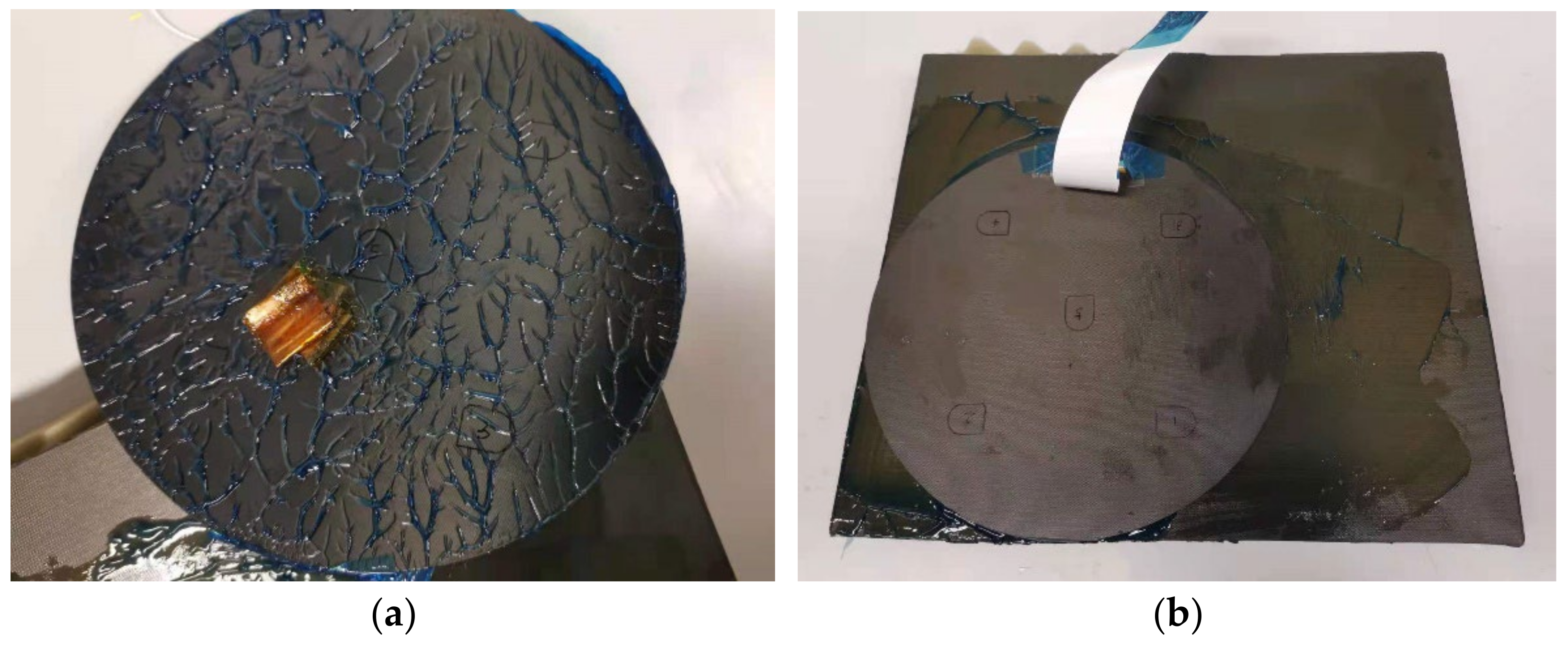
After lay-up and bagging, the patch was cured at 180 °C in the autoclave and the curing cycle was set up according to the prepregs’ datasheet. After curing and trimming, a connector (RS 514-4408, operating temperature range: −40 °C to +85 °C) was mounted on the surface of the repair patch and bonded by a super glue (RS 473-445, operating temperature range: −50 °C to +80 °C) to connect circuits and embedded PZT transducers by conductive epoxy adhesive resin/hardener (RS 186-3616). After the fabrication, the trimmed repair patch is shown in Figure 2b. For manufacturing the host composite structure, a quasi-isotropic stacking sequence (0°/+45°/−45°/+90°)4s was used for the layup and the size was 300 mm × 260 mm, and the thickness of the host structure was about 4 mm after curing.
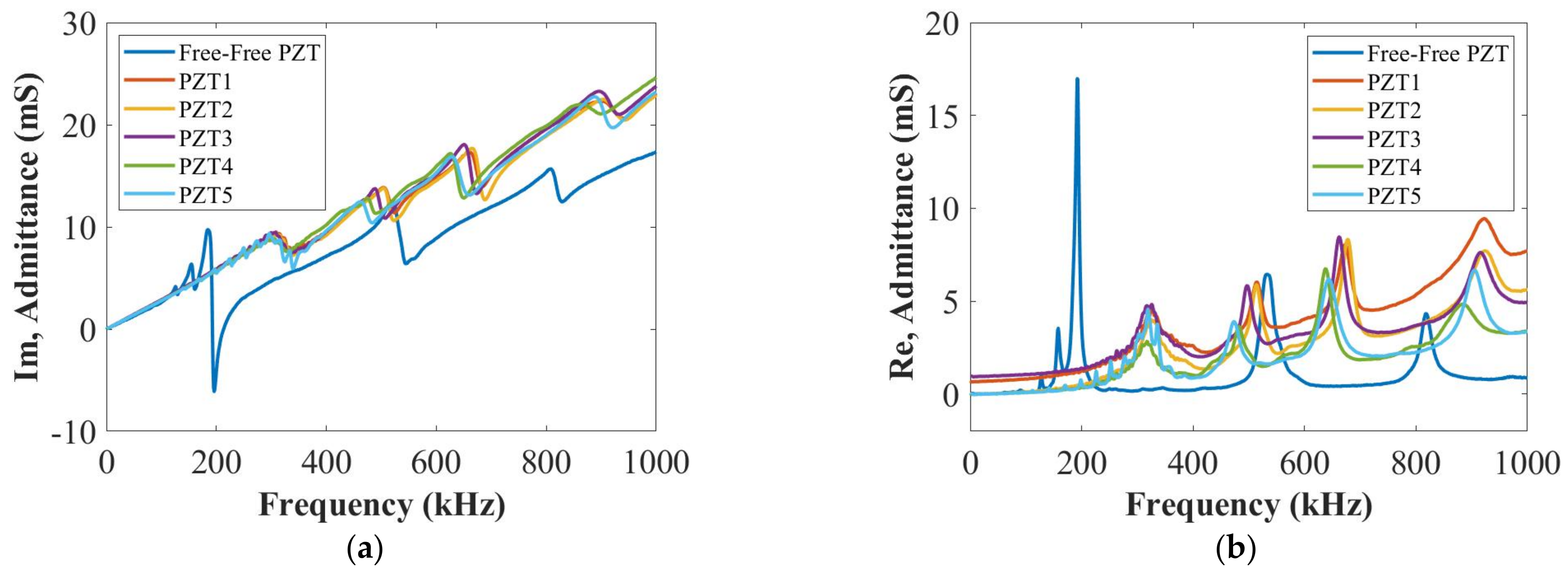
After manufacturing, the EMI method was used to evaluate the bonding properties between the PZT transducer and the repair patch. The EMI method can be used to evaluate local damage severities, transducers’ fractures, mechanical/electrical properties for the degradation and integrity of bonding properties [35]. According to the EMI method, the imaginary part of admittance at a low-frequency range will make the mechanical impedance of the composite structure close to zero and only the mechanical impedance of the PZT transducer is considered [41]. Therefore, any slope change in the imaginary part of admittance at the low-frequency range will determine the integrity of bonding properties between the host structure and the PZT transducers [35].
In the experiments, a SinePhase Impedance Analyzer (Model 16777K) was used for measuring the imaginary and real parts of admittance at room temperature. Figure 3 presents EMI results for the imaginary and real parts of admittances for different embedded PZT transducers. As is shown in Figure 3a, slopes of imaginary parts of the admittance for all embedded PZT transducers at the low-frequency range do not show an obvious difference. Hence, the bonding qualities were good for these embedded PZT transducers, and they can be further used for active sensing SHM purposes.

3. Damage Detection and Localization

To verify if the smart repair patch embedded with diagnostic film and PZT transducers can monitor the integrity of the bondline quality, the damage index (DI) correlation coefficient and delay-and-sum (DAS) algorithm based on active sensing were used to detect and locate the bondline defects. In this section, two types of defects were studied, which were artificial delamination and surface-mounted artificial damage. In addition, blue contact gel was fully applied to the repair patch to bond it with the composite host structure as baseline signals (as is shown in Figure 4a). Here, the contact gel was used in DolphiCam C-Scan to improve the coupling on rougher surfaces. The reason for using this contact gel was that the repair patch could be easily removed at room temperature and used for further measurements. For simulating delamination and measuring the current signals, the repair patch was removed and two layers of KAPTON® films were inserted in the designated positions of the repair patch (shown in Figure 4b). The repair patch was then put back to the original position as close as possible. To detect the surface-mounted artificial damage, a weighted blue-tack was placed in designated positions on the surface of the repair patch and bottom of the host structure as the current signals.
For measuring guided waves, a National Instrument (NI) PXIe-1073 and an arbitrary signal generator (NI PXI-5412) were used for signal generation, and a digitizer (NI PXI-5105) was used to record UGW signals. During the measurements, the time-of-arrival (ToA) of the A0 mode could not be distinguished at 50 kHz due to the overlap between the crosstalk and the first wave packet of each measured signal. Therefore, a five-cycle Hanning-windowed toneburst signal at 250 kHz [42] was used as the actuation signal. The actuation amplitude and sampling frequency were 6 V and 100 MHz, respectively. Both baseline and current signals were measured at room temperature.

3.1. Delamination

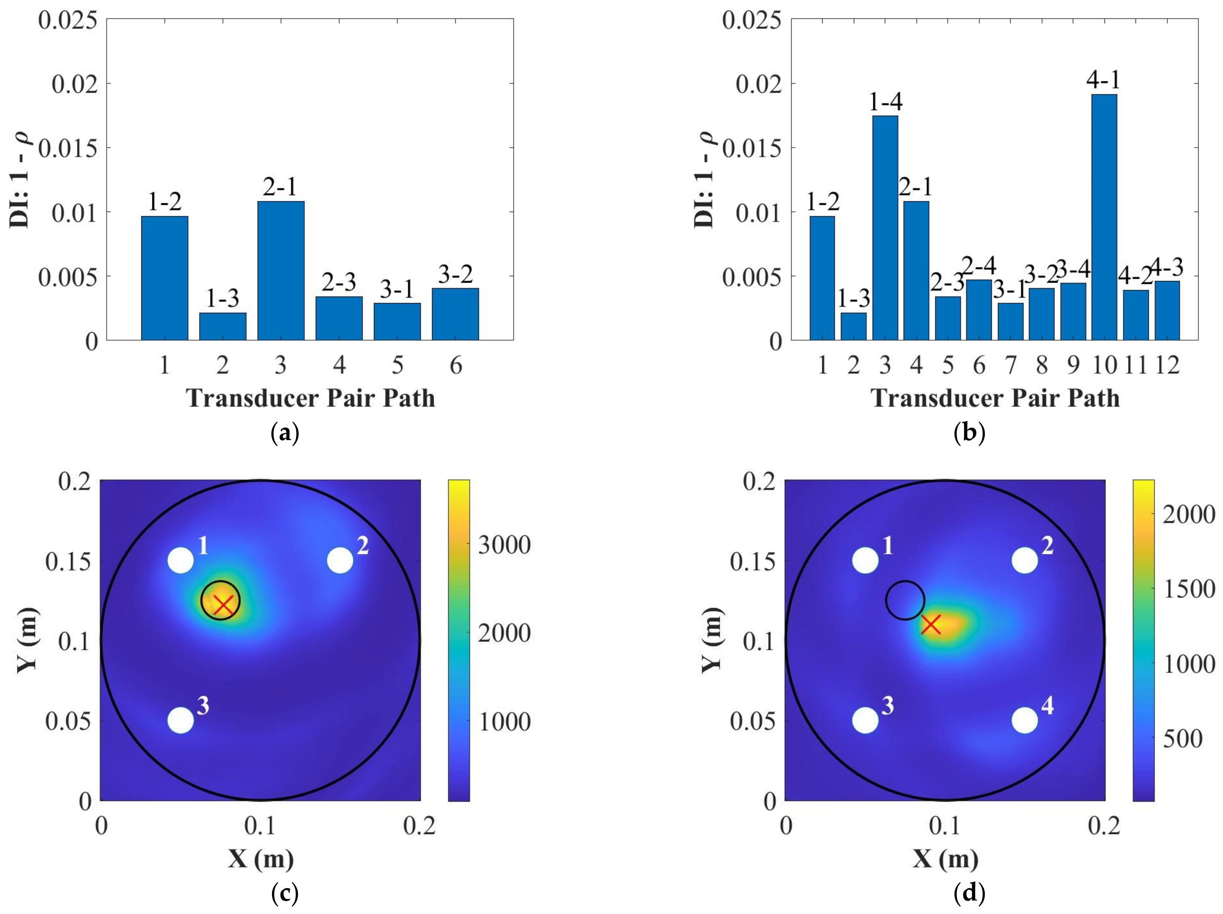
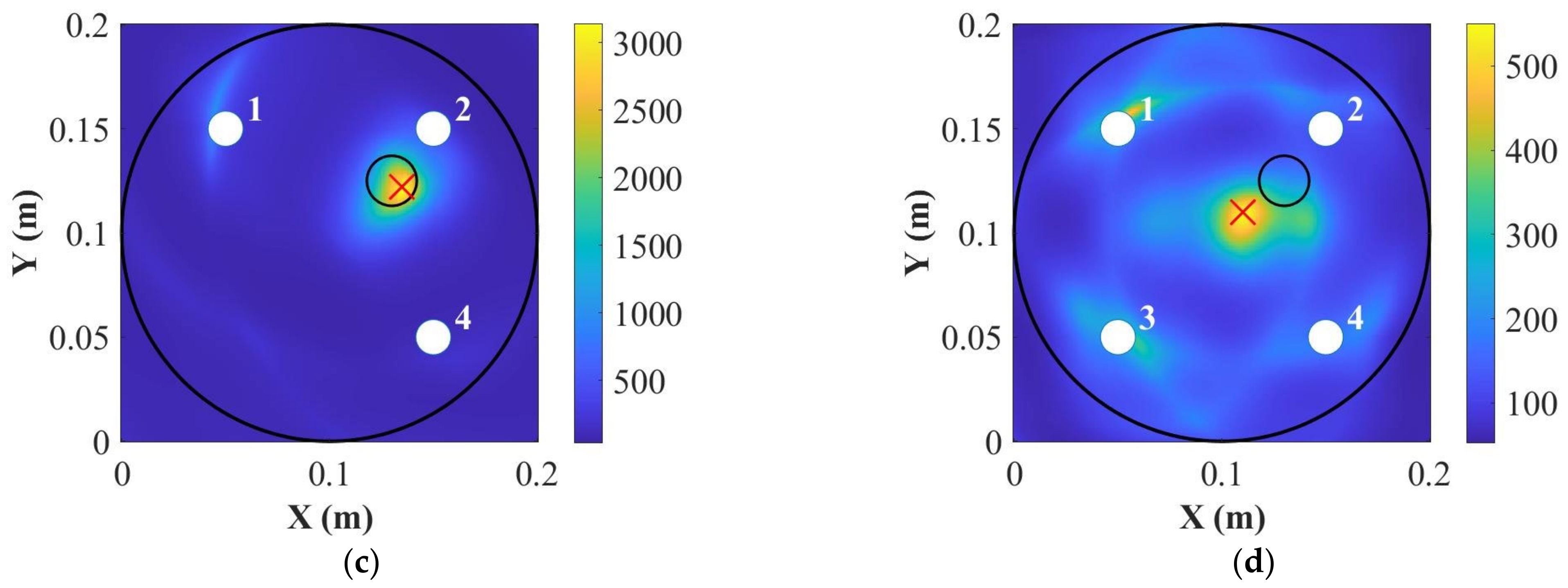
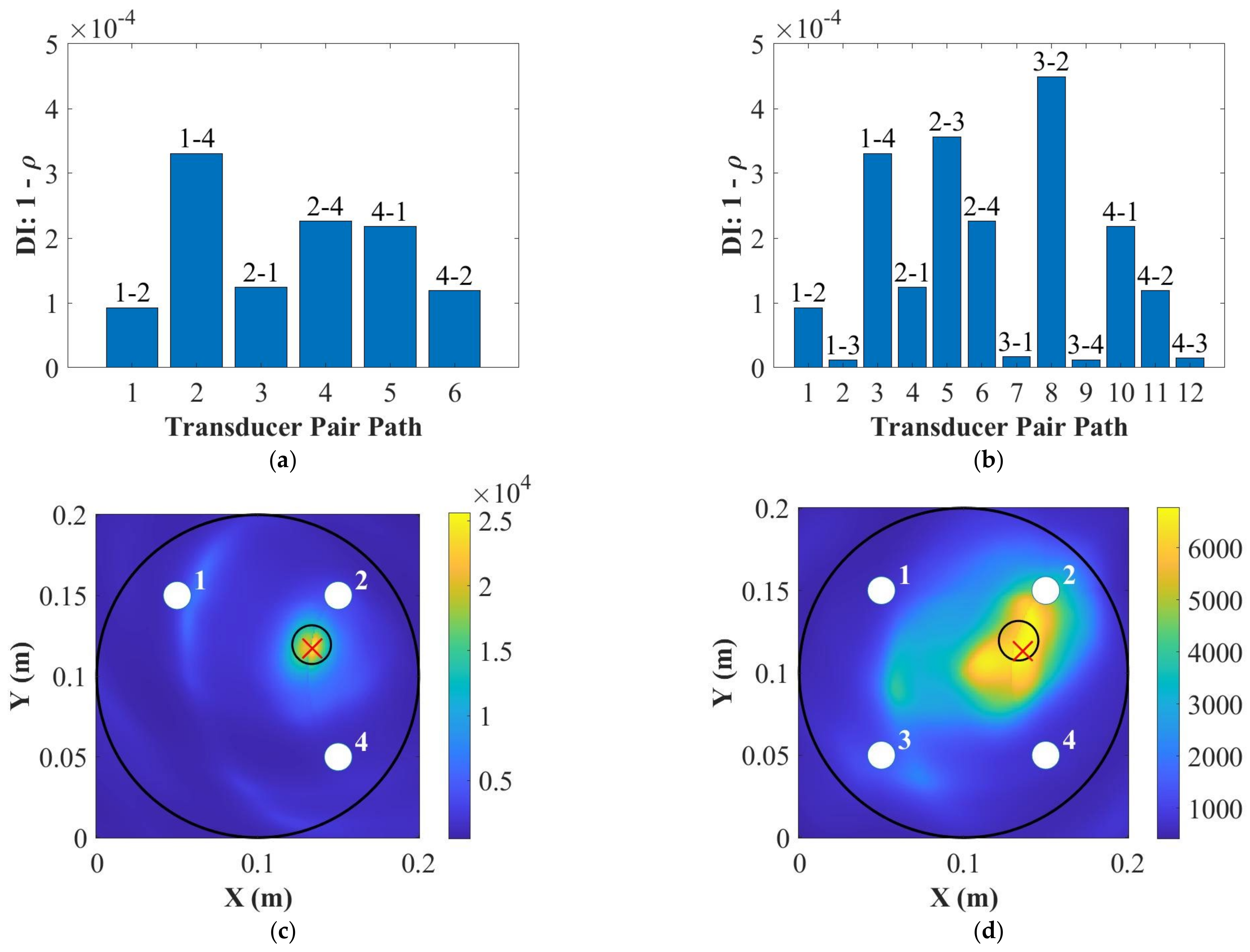
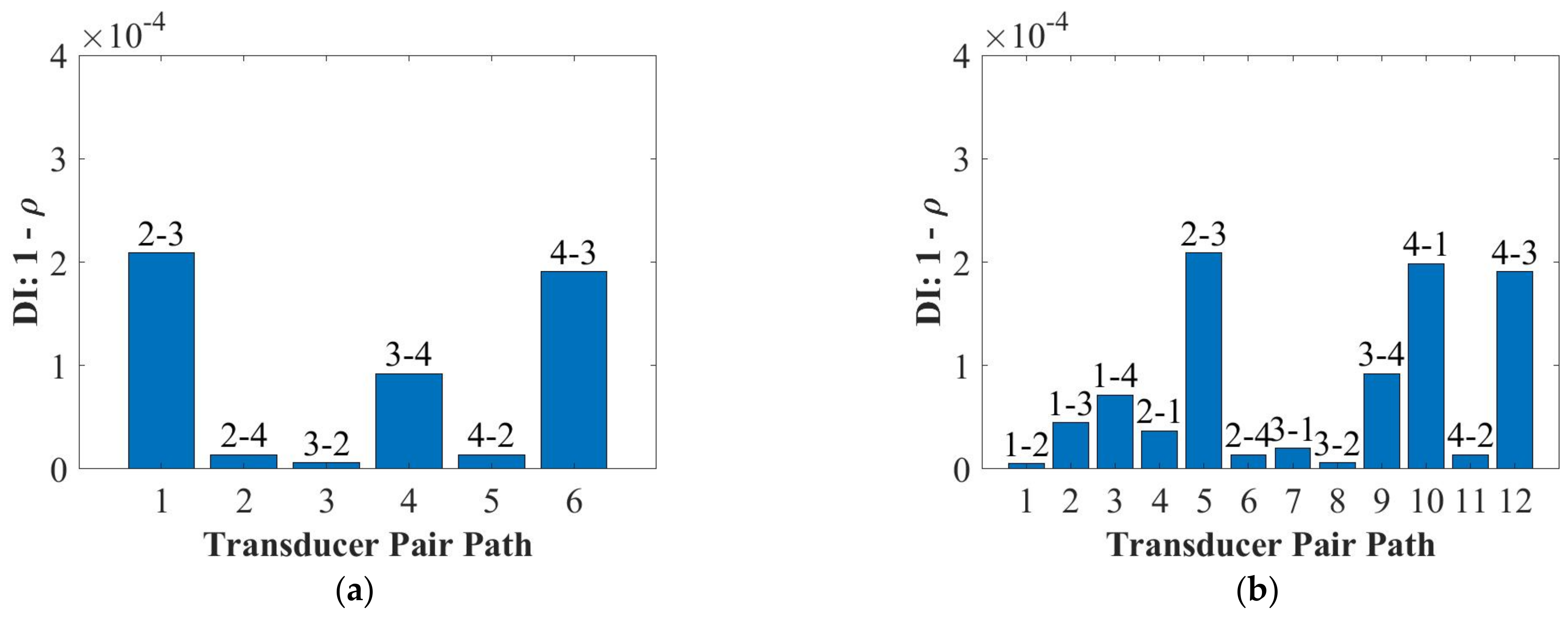
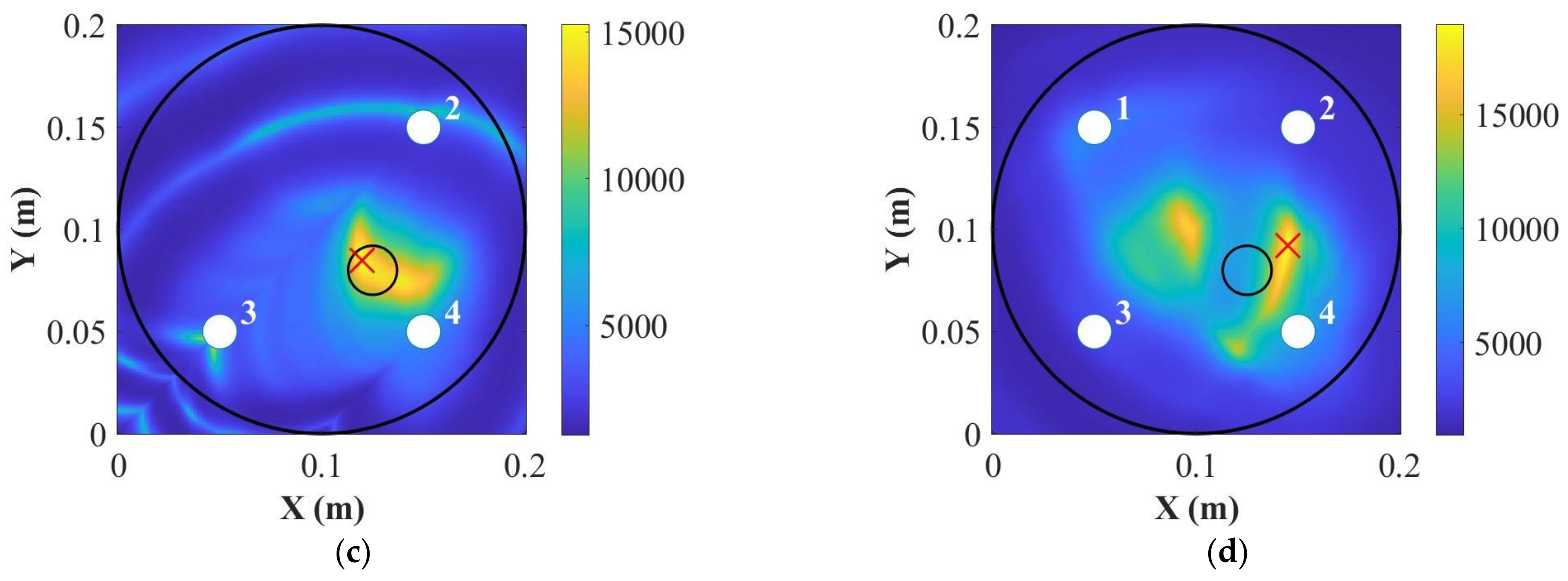
Figure 5 and Figure 6 compare the results of damage detections and localizations for two artificial delamination positions at 250 kHz by using three and four PZT transducers, respectively. The results show that the DI results using both three and four PZT transducers can detect the damage. The DAS results show that the artificial delamination can be located accurately using three PZT transducers but cannot when using four PZT transducers. Two factors affected the locating results during the measurements. First, the repair patch cannot be placed in the same position as the baseline status after inserting the KAPTON® films into bondline positions. In addition, the thickness of the contact gel used to bond the repair patch and the host structure cannot be kept at the same value since the contact gel will come back again every time after hardly pushing the repair patch. Both factors would affect the measured signals. Therefore, using four or more PZT transducers will cause the inaccuracy of damage localization due to the inconsistency caused by the contact gel.
However, the smart repair patch will be bonded to the host structure permanently by resin film for the actual situation. First, the repaired structure bonded by the resin film will make the patch maintain its original position when delamination happened and retain the same thickness of the bonding area. Furthermore, the selection of the contact glue to bond the patch and host structure is a compromising way under laboratory conditions and no alternative material can be found to bond the repaired structure together and peel them after measuring. Hence, the above two factors would not affect the measuring results when using four PZT transducers, and it can be confirmed that the DAS results would be accurate when using four PZT transducers for the actual repair.

3.2. Surface-Mounted Artificial Damage—Surface of the Repair Patch

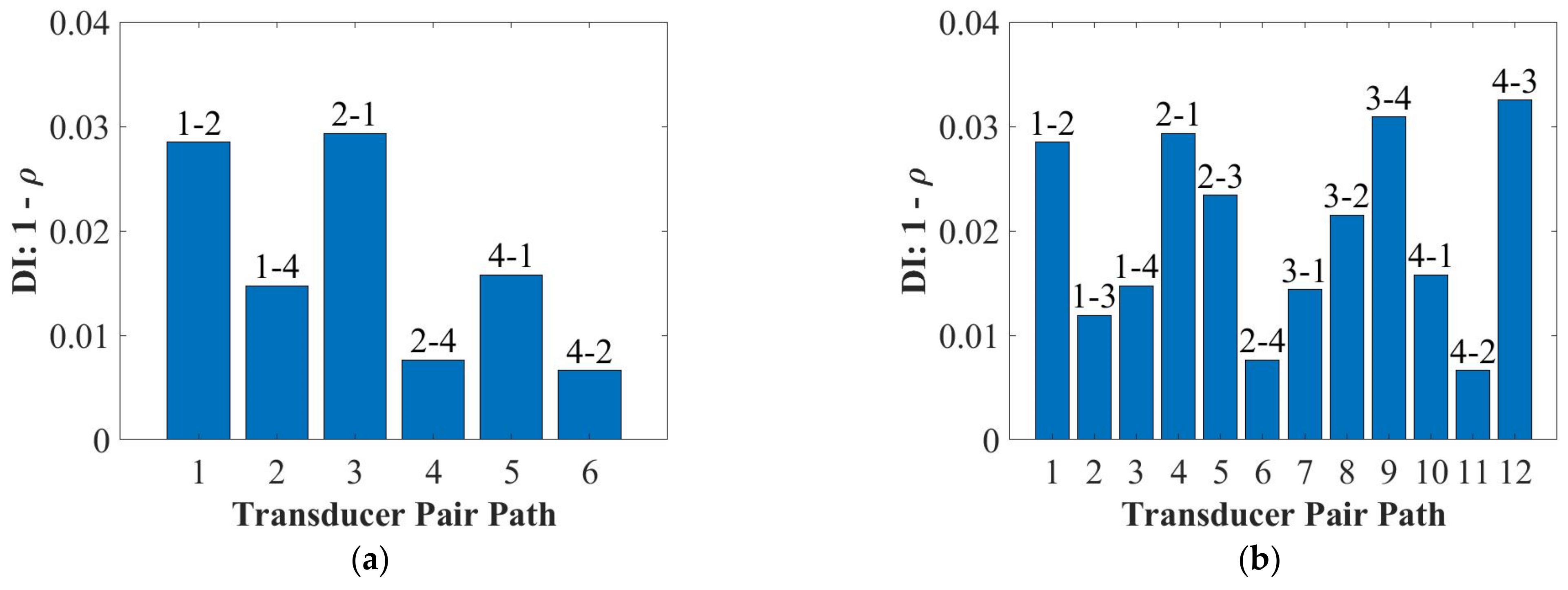
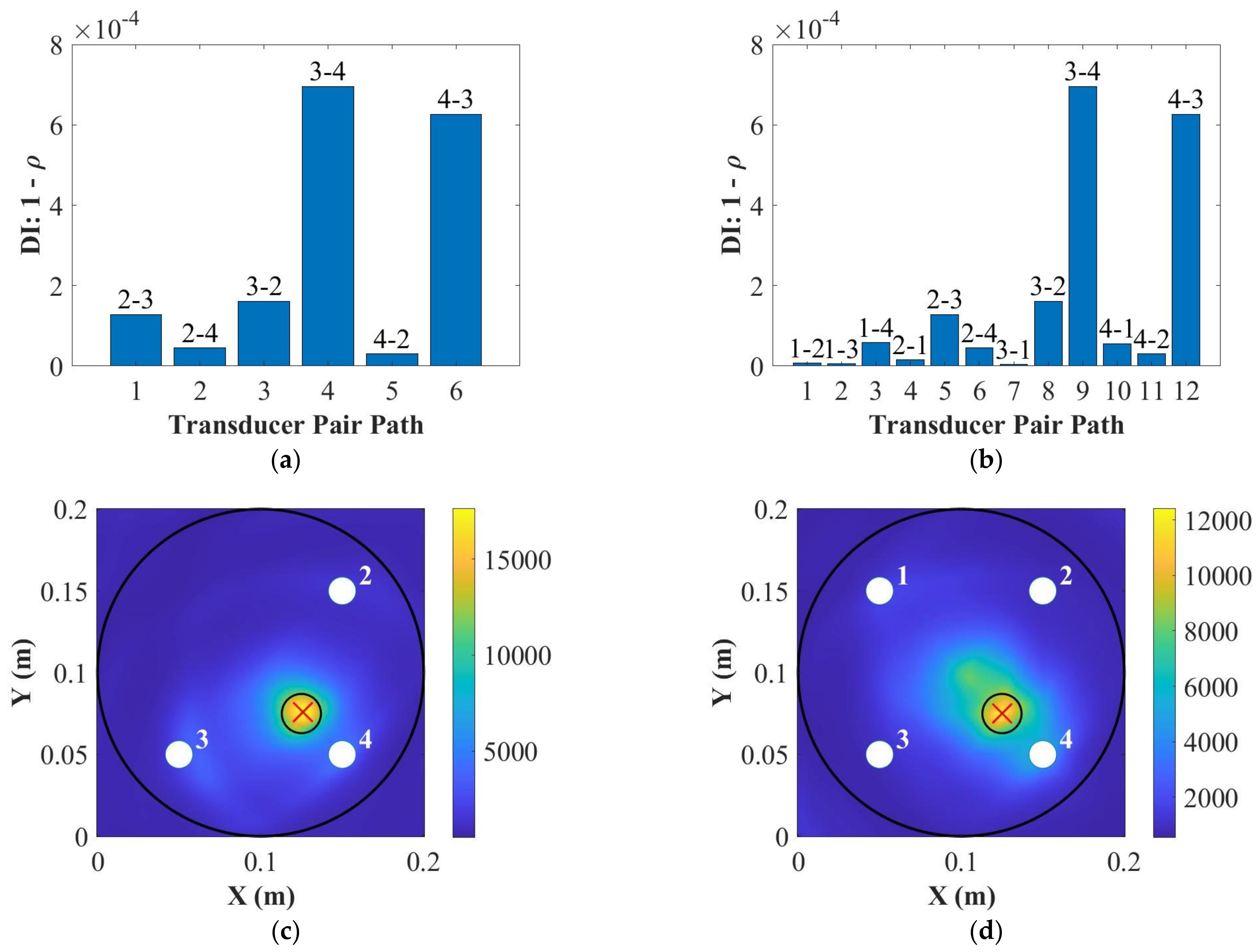
To simulate the repair patch suffering surface damage, a weighted blue tack was attached on the surface of the repair patch. Figure 7 and Figure 8 show the results of damage detection and localization for the surface-mounted artificial damage attached on the surface of the repair patch. As can be seen in Figure 7 and Figure 8, using both three and four PZT transducers can detect and locate the damage accurately. In this situation, the blue tack was removed from the surface of the repair patch only, so the using of contact gel would not become the factor affecting the accuracy of the localization results.

3.3. Surface-Mounted Artificial Damage—Bottom of the Host Structure

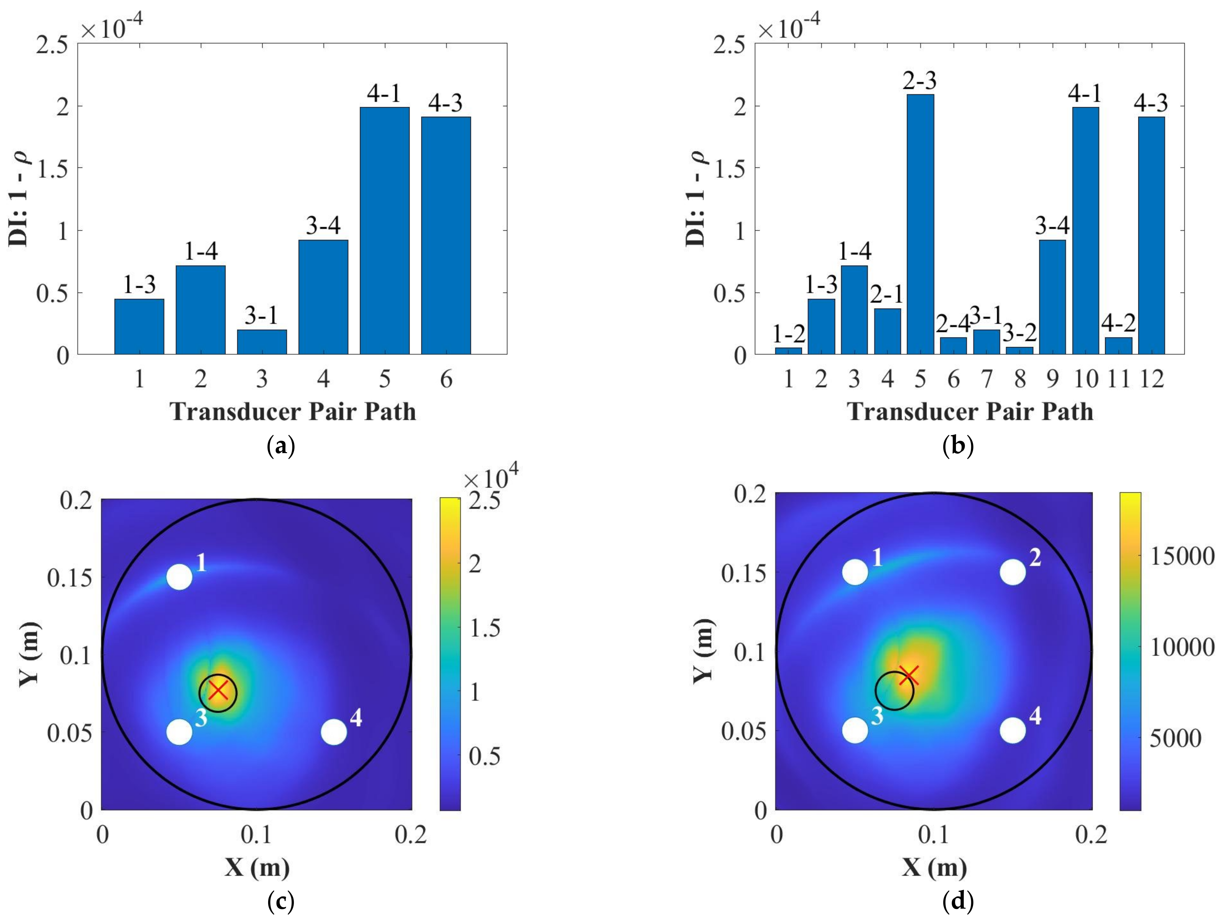
To simulate the host structure suffering damage, a weighted blue tack was attached on the bottom of the host structure, which was the surface of the opposite side of the repair patch. Figure 9 and Figure 10 show the damage detection and localization for the surface-mounted artificial damage attached on the bottom of the host structure. As can be seen in Figure 9 and Figure 10, using both three and four PZT transducers can detect the damage. However, the DAS algorithm can locate the damage more accurately using three PZT transducers than using four PZT transducers. The reason why five PZT transducers were not used for damage localization is that the repair patch is relatively small and having more sensors installed generate more noise in the signals. This can be seen with the results from three and four PZT transducers that the noise in the signal was high enough to mask the scattering from the damage.

4. Conclusions

This paper developed a smart repair patch using the diagnostic film embedded into the patch using an edge cut-out method. This film has been verified to perform well under extreme environmental and operational conditions. Electro-mechanical impedance results showed that embedded lead zirconate titanate transducers’ bonding qualities were good after manufacturing. For damage detection and localization, the damage index correlation coefficient and delay-and-sum algorithm based on the active sensing technique were used. In addition, blue contact gel was used to bond the repair patch and host structure together for easier removing the patch and inserting KAPTON® films to create artificial delamination. Furthermore, the A0 mode at 50 kHz was not applicable due to the overlap between the crosstalk and the first wave packet of measured signals.
According to the damage index results, the use of a smart repair patch can detect the artificial delamination and surface-mounted artificial damage at 250 kHz using both three and four lead zirconate titanate transducers. Furthermore, the smart repair patch can locate the delamination using three lead zirconate titanate transducers and surface-mounted artificial damage using four lead zirconate titanate transducers accurately. Since the resin film was replaced by blue contact gel for simulating the bonding and caused the inconsistency and uncertainty between the baseline and current signals due to removing the patch and inserting delamination, so the delay-and-sum results were not accurate when using four lead zirconate titanate transducers for the S0 mode at 250 kHz. However, the use of resin film will keep the composite repair structure consistent and it can be confirmed that using four transducers will locate the delamination accurately using the delay-and-sum algorithm for actual composite repair. Therefore, the smart repair patch embedded with the developed diagnostic film and lead zirconate titanate transducers can be used to detect and locate bondline defects of repaired composite structures based on Structural Health Monitoring techniques.

Author Contributions

Experimental work, analysis and preparation of the manuscript, T.F.; supervision of the research and preparation of the manuscript, M.H.F.A. All authors have read and agreed to the published version of the manuscript.

Funding

This research received no external funding. T. Feng’s scholarship is supported by the Aviation Industry Corporation of China, Ltd. (AVIC).

Institutional Review Board Statement

Not applicable.

Informed Consent Statement

Not applicable.

Data Availability Statement

Not applicable.

Acknowledgments

The first author wishes to acknowledge the funding from the Aviation Industry Corporation of China, Ltd. (AVIC), AVIC General Huanan Aircraft Industry Co., Ltd. and the China Scholarship Council (No. [2017] 5082).

Conflicts of Interest

The authors declare no conflict of interest.

References

  1. Flor, F.R.; De Medeiros, R.; Tita, V. Numerical and Experimental Damage Identification in Metal-Composite Bonded Joint. J. Adhes. 2014, 91, 863–882. [Google Scholar] [CrossRef]
  2. Sikdar, S.; Fiborek, P.; Malinowski, P.; Ostachowicz, W. Ultrasonic guided wave propagation in a repaired stiffened composite panel. In Proceedings of the Health Monitoring of Structural and Biological Systems XIII, Denver, CO, USA, 3–7 March 2019. [Google Scholar]
  3. Lambinet, F.; Khodaei, Z.S. Damage detection & localization on composite patch repair under different environmental effects. Eng. Res. Express 2020, 2, 045032. [Google Scholar] [CrossRef]
  4. Katnam, K.B.; Comer, A.J.; Roy, D.; da Silva, L.; Young, T. Composite Repair in Wind Turbine Blades: An Overview. J. Adhes. 2015, 91, 113–139. [Google Scholar] [CrossRef]
  5. Spearing, S.M.; Lagace, P.A.; McManus, H.L.N. On the Role of Lengthscale in the Prediction of Failure of Composite Structures: Assessment and Needs. Appl. Compos. Mater. 1998, 5, 139–149. [Google Scholar] [CrossRef]
  6. Gryzagoridis, J.; Findeis, D. Benchmarking shearographic NDT for composites. Insight-Non-Destr. Test. Cond. Monit. 2008, 50, 249–252. [Google Scholar] [CrossRef] [Green Version]
  7. Katnam, K.B.; Dhôte, J.X.; Young, T.M. Experimental analysis of the bondline stress concentrations to characterize the influence of adhesive ductility on the composite single lap joint strength. J. Adhes. 2013, 89, 486–506. [Google Scholar] [CrossRef]
  8. Gharib, H. Structural Health Monitoring of Adhesive Bond in Aircraft Repair Patches. Available online: https://www.researchgate.net/profile/Hossam-Gharib/publication/282121093_A_Review_on_Structural_Health_Monitoring_of_Adhesive_Bond_in_Aircraft_Repair_Patches/links/56036a9508ae596d2591e664/A-Review-on-Structural-Health-Monitoring-of-Adhesive-Bond-in-Aircraft-Repair-Patches.pdf (accessed on 20 March 2022).
  9. Sherwin, G.R. Non-autoclave processing of advanced composite repairs. Int. J. Adhes. Adhes. 1999, 19, 155–159. [Google Scholar] [CrossRef]
  10. Brostow, W.; Glass, N.M. Cure progress in epoxy systems: Dependence on temperature and time. Mater. Res. Innov. 2003, 7, 125–132. [Google Scholar] [CrossRef]
  11. Katnam, K.; Comer, A.; Stanley, W.; Buggy, M.; Ellingboe, A.; Young, T. Characterising pre-preg and non-crimp-fabric composite single lap bonded joints. Int. J. Adhes. Adhes. 2011, 31, 679–686. [Google Scholar] [CrossRef]
  12. Lambinet, F.; Khodaei, Z.S. Development of smart bonded composite patch repair solution. AIP Conf. Proc. 2020, 2309, 020009. [Google Scholar]
  13. Lambinet, F.; Khodaei, Z.S.; Aliabadi, F.M. Effectiveness of RAPID and SSM Algorithms on Composite Scarf Repair. Key Eng. Mater. 2018, 774, 535–540. [Google Scholar] [CrossRef]
  14. Zhu, J.; Wang, Y.; Qing, X. A real-time electromechanical impedance-based active monitoring for composite patch bonded repair structure. Compos. Struct. 2019, 212, 513–523. [Google Scholar] [CrossRef]
  15. Rocha, H.; Semprimoschnig, C.; Nunes, J.P. Sensors for process and structural health monitoring of aerospace composites: A review. Eng. Struct. 2021, 237, 112231. [Google Scholar] [CrossRef]
  16. Su, Z.; Ye, L. Identification of Damage Using Lamb Waves: From Fundamentals to Applications; Springer Science & Business Media: Berlin, Germany, 2009. [Google Scholar]
  17. Giurgiutiu, V.; Zagrai, A.; Bao, J.J. Piezoelectric Wafer Embedded Active Sensors for Aging Aircraft Structural Health Monitoring. Struct. Health Monit. 2002, 1, 41–61. [Google Scholar] [CrossRef]
  18. Kim, H.S.; Ghoshal, A.; Chattopadhyay, A.; Prosser, W.H. Development of Embedded Sensor Models in Composite Laminates for Structural Health Monitoring. J. Reinf. Plast. Compos. 2004, 23, 1207–1240. [Google Scholar] [CrossRef]
  19. Dib, G.; Koricho, E.G.; Karpenko, O.; Haq, M.; Udpa, L.; Udpa, S.S. Feasibility of PZT ceramics for impact damage detection in composite structures. AIP Conf. Proc. 2015, 1650, 1072–1080. [Google Scholar] [CrossRef]
  20. Qiu, Y.; Wang, Q.-B.; Zhao, H.-T.; Chen, J.-A.; Wang, Y.-Y. Review on composite structural health monitoring based on fiber Bragg grating sensing principle. J. Shanghai Jiaotong Univ. (Science) 2013, 18, 129–139. [Google Scholar] [CrossRef]
  21. Giurgiutiu, V. Structural Health Monitoring of Aerospace Composites; Academic Press: Cambridge, MA, USA, 2015. [Google Scholar]
  22. Güemes, A.; Fernández-López, A.; Díaz-Maroto, P.F.; Lozano, A.; Sierra-Perez, J. Structural health monitoring in composite structures by fiber-optic sensors. Sensors 2018, 18, 1094. [Google Scholar] [CrossRef] [Green Version]
  23. Jinachandran, S.; Rajan, G. Fibre Bragg Grating Based Acoustic Emission Measurement System for Structural Health Monitoring Applications. Materials 2021, 14, 897. [Google Scholar] [CrossRef]
  24. Zhao, X.; Gao, H.; Zhang, G.; Ayhan, B.; Yan, F.; Kwan, C.; Rose, J.L. Active health monitoring of an aircraft wing with embedded piezoelectric sensor/actuator network: I. Defect detection, localization and growth monitoring. Smart Mater. Struct. 2007, 16, 1208–1217. [Google Scholar] [CrossRef]
  25. Aliabadi, M.H.F.; Khodaei, Z.S. Structural Health Monitoring for Advanced Composite Structures; World Scientific Publishing Europe Ltd.: London, UK, 2017. [Google Scholar]
  26. Güemes, A.; Fernandez-Lopez, A.; Pozo, A.R.; Sierra-Pérez, J. Structural Health Monitoring for Advanced Composite Structures. J. Compos. Sci. 2020, 4, 13. [Google Scholar] [CrossRef] [Green Version]
  27. Michaels, J.E. Detection, localization and characterization of damage in plates with an in situ array of spatially distributed ultrasonic sensors. Smart Mater. Struct. 2008, 17, 035035. [Google Scholar] [CrossRef] [Green Version]
  28. Khodaei, Z.S.; Aliabadi, M.H. Assessment of delay-and-sum algorithms for damage detection in aluminium and composite plates. Smart Mater. Struct. 2014, 23, 075007. [Google Scholar] [CrossRef]
  29. Rito, R.; Crocombe, A.; Ogin, S. Health monitoring of composite patch repairs using CFBG sensors: Experimental study and numerical modelling. Compos. Part A Appl. Sci. Manuf. 2017, 100, 255–268. [Google Scholar] [CrossRef]
  30. Roth, W.; Giurgiutiu, V. Structural health monitoring of an adhesive disbond through electromechanical impedance spectroscopy. Int. J. Adhes. Adhes. 2017, 73, 109–117. [Google Scholar] [CrossRef]
  31. Qing, X.; Beard, S.J.; Kumar, A.; Hannum, R. A real-time active smart patch system for monitoring the integrity of bonded repair on an aircraft structure. Smart Mater. Struct. 2006, 15, N66–N73. [Google Scholar] [CrossRef]
  32. Bekas, D.G.; Sharif-Khodaei, Z.; Baltzis, D.; Aliabadi, M.F.; Paipetis, A.S. Quality assessment and damage detection in nanomodified adhesively-bonded composite joints using inkjet-printed interdigital sensors. Compos. Struct. 2019, 211, 557–563. [Google Scholar] [CrossRef]
  33. Sánchez-Romate, X.F.; García, C.; Rams, J.; Sánchez, M.; Ureña, A. Structural health monitoring of a CFRP structural bonded repair by using a carbon nanotube modified adhesive film. Compos. Struct. 2021, 270, 114091. [Google Scholar] [CrossRef]
  34. Bekas, D.G.; Sharif-Khodaei, Z.; Aliabadi, M.F. An Innovative Diagnostic Film for Structural Health Monitoring of Metallic and Composite Structures. Sensors 2018, 18, 2084. [Google Scholar] [CrossRef] [Green Version]
  35. Feng, T.; Bekas, D.; Aliabadi, M.H.F. Active Health Monitoring of Thick Composite Structures by Embedded and Surface-Mounted Piezo Diagnostic Layer. Sensors 2020, 20, 3410. [Google Scholar] [CrossRef]
  36. Lin, M.; Chang, F.-K. Composite structures with built-in diagnostics. Mater. Today 1999, 2, 18–22. [Google Scholar] [CrossRef]
  37. Feng, T.; Aliabadi, M.F. Structural Integrity Assessment of Composites Plates with Embedded PZT Transducers for Structural Health Monitoring. Materials 2021, 14, 6148. [Google Scholar] [CrossRef]
  38. Salmanpour, M.S.; Khodaei, Z.S.; Aliabadi, M.H. Airborne Transducer Integrity under Operational Environment for Structural Health Monitoring. Sensors 2016, 16, 2110. [Google Scholar] [CrossRef] [PubMed] [Green Version]
  39. Yue, N.; Khodaei, Z.S.; Aliabadi, M.H. Damage detection in large composite stiffened panels based on a novel SHM building block philosophy. Smart Mater. Struct. 2021, 30, 045004. [Google Scholar] [CrossRef]
  40. Xu, C.; Khodaei, Z.S. A Novel Fabry-Pérot Optical Sensor for Guided Wave Signal Acquisition. Sensors 2020, 20, 1728. [Google Scholar] [CrossRef] [PubMed] [Green Version]
  41. Park, G.; Farrar, C.R.; Di Scalea, F.L.; Coccia, S. Performance assessment and validation of piezoelectric active-sensors in structural health monitoring. Smart Mater. Struct. 2006, 15, 1673–1683. [Google Scholar] [CrossRef]
  42. Zou, F.; Benedetti, I.; Aliabadi, M.H. A boundary element model for structural health monitoring using piezoelectric transducers. Smart Mater. Struct. 2014, 23, 015022. [Google Scholar] [CrossRef] [Green Version]
Figure 1. Schematics of (a) general drawing of repair patch and (b) embedding procedure during layup.
Applsci 12 04916 g001
Figure 2. Schematics of (a) embedding procedure and (b) trimmed smart repair patch.
Applsci 12 04916 g002
Figure 3. The EMI results of (a) imaginary and (b) real part of admittance for different PZT transducers.
Applsci 12 04916 g003
Figure 4. Schematics of (a) artificial delamination and (b) bonding with blue contact gel for the bonded repair structures.
Applsci 12 04916 g004
Figure 5. Delamination detection using (a) three PZT transducers and (b) four PZT transducers, and localization using (c) three PZT transducers and (d) four PZT transducers at 250 kHz for the position 1 (where the “○” is the position for real damage and the “ × ” is the position for predicted damage).
Applsci 12 04916 g005
Figure 6. Delamination detection using (a) three PZT transducers and (b) four PZT transducers, and localization using (c) three PZT transducers and (d) four PZT transducers at 250 kHz for the position 2 (where the “○” is the position for real damage and the “ × ” is the position for predicted damage).
Applsci 12 04916 g006aApplsci 12 04916 g006b
Figure 7. Detection of surface-mounted artificial damage on the surface of the repair patch using (a) three PZT transducers and (b) four PZT transducers, and localization using (c) three PZT transducers and (d) four PZT transducers at 250 kHz for the position 1 (where the “○” is the position for real damage and the “ × ” is the position for predicted damage).
Applsci 12 04916 g007
Figure 8. Detection of surface-mounted artificial damage on the surface of the repair patch using (a) three PZT transducers and (b) four PZT transducers, and localization using (c) three PZT transducers and (d) four PZT transducers at 250 kHz for the position 2 (where the “○” is the position for real damage and the “ × ” is the position for predicted damage).
Applsci 12 04916 g008
Figure 9. Detection of surface-mounted artificial damage on the bottom of the host structure using (a) three PZT transducers and (b) four PZT transducers, and localization using (c) three PZT transducers and (d) four PZT transducers at 250 kHz for the position 1 (where the “○” is the position for real damage and the “ × ” is the position for predicted damage).
Applsci 12 04916 g009
Figure 10. Detection of surface-mounted artificial damage on the bottom of the host structure using (a) three PZT transducers and (b) four PZT transducers, and localization using (c) three PZT transducers and (d) four PZT transducers at 250 kHz for the position 2 (where the “○” is the position for real damage and the “ × ” is the position for predicted damage).
Applsci 12 04916 g010aApplsci 12 04916 g010b
Publisher’s Note: MDPI stays neutral with regard to jurisdictional claims in published maps and institutional affiliations.