1. Introduction
Electric propulsion is the future of transportation [
1], which is why research in trains to overcome current speeds is widely being conducted nowadays. In this sense, aerodynamics is not a minor issue if higher velocity is to be achieved. Apart from other limits, such as the catenary contact [
2] or the wheel-rail contact [
3], aerodynamics is present in the ground transportation systems as a strong limitation, especially when it comes to tunnels.
A new generation of High-Speed Rails (HSRs), particularly maglev trains, aspire to run at very high speeds. They will require straighter tracks and longer and more numerous tunnel sections to avoid obstacles and to reduce environmental impacts. The projects in mountainous countries, such as Switzerland and Japan require special mention [
4]. An example is the tunnels to be built through the Alps, the Lyon-Torino (54 km long tunnel), or the Swiss AlpTransit project with 120 km of tunnels. Moreover, in Japan, the new Maglev Yamanashi test line has 82 % of the total route (42.8 km) inside tunnels.
One evolution of conventional trains is the Evacuated-Tube Train (ETT), in which the train, or capsule, runs insides a tunnel during the whole track. This closed environment enables it to reduce the operating pressure and therefore the aerodynamic resistance. Not only drag but also the impact of certain flow patterns present in HSR tunnels are minimized when decreasing the pressure. If reducing the pressure is proposed as a solution to surpass current speed limitations, which is one of the focuses of the present work, it is important to remark that construction costs become more significant as the whole route has to be confined inside a tube. However, an optimal cross-sectional design can reduce the investment considerably.
Elon Musk in 2013 took the concept of vacuum train one step forward, naming it as the hyperloop on its document, the Hyperloop Alpha [
5]. Musk proposed the combination of levitating trains and a low-pressure environment. Although he planned on using air bearings for levitation, the concept could be adapted to use other types of levitation, such as magnetic ones. The same happens with propulsion, as he proposed the capsules to be driven by linear induction motors. However, other methods such as aerodynamic propulsion might be considered. The latter is preliminarily studied in the present work.
Back to the aerodynamic problem, certain issues are peculiar to the movement of trains inside tunnels, and they do not appear in open air [
4]. One of these problems is the compression and expansion waves generated when the train enters the tunnel. This scenario has to be taken into consideration during the design process of a standard HSR. Other authors have also researched this topic. Ehrendorfer et al. [
6] analyzed this particular entrance effect. Kwon et al. [
7] used the response surface methodology and axisymmetric compressible Euler equations to optimize the nose shape of a train and minimize the tunnel compression wave. More work about nose optimization was conducted by Choi and Kim in [
8] and by Zhang in [
9].
Conventional trains inside tunnels, ETTs, and hyperloops all involve the analysis of moving objects at high speeds within a confined space. In this environment, two main sources provoke drag [
10,
11]. One of them is the choking of the flow when the local Mach number reaches its critical level. The second one is the presence of shock waves at transonic and supersonic speeds that travel through the tube. When critical Mach is reached, a high-pressure blockage is generated in front of the capsule, endangering the operability of this system.
In this sense, the Hyperloop Alpha [
5] proposes two methods to delay both effects in ETT or hyperloop. One method consists of increasing the size of the tube to reduce the blockage ratio of the capsule, which directly affects the cost of the infrastructure. The other is to add a compressor to the vehicle, which will increase the pressure of the swallowed air, preventing its acceleration and choking. The addition of a compressor will allow the use of smaller tunnels before reaching transonic speeds, reducing the cost of the infrastructure. In any case, the tube pressure can be lowered to reduce the impact of transonic patterns.
Taking into consideration the pressure as a variable, the ratio between the cross-sectional area of the capsule and the tunnel (known as Blockage Ratio or BR) and the speed of the vehicle, several studies varying these parameters arise [
8,
12,
13,
14], including one from the same authors of the present work in [
15]. Chen et al. [
16] added the effect of the levitating gaps in their confined simulations. Other authors performed similar parametric studies [
12], varying pressures, speeds, and diameters. Liu et al. [
17] also provided significant conclusions, as they reported that the friction drag is far smaller than the pressure drag. They also noticed that the aerodynamic and pressure drag coefficients do not vary with the tube pressure, but change considerably with the BR. The drag itself varied linearly with the pressure and almost squarely with the train speed.
A similar study was performed by Zhang [
9], who varied the length of the nose to reduce the aerodynamic drag at 0.2 atm and 800 km/h, with a BR of 0.2. Oh et al. [
14] analyzed a wide range of pressures, concluding that the pressure drag was significantly affected by the increase in BR. Yang et al. [
18] also reported that different operating speeds and working vacuum pressures significantly affected the resistance of the capsule and investigated the head and tail of the train to minimize this force.
The connection between the vacuum tubes has also been the object of study by other authors. Jia et al. [
19] studied the Pressure Recycle Ducts (PRD) and the influence of the interval length and opening width of PRD on the differential pressure. A similar work was conducted in [
4] for the Swissmetro project, which is equivalent to the hyperloop concept.
The effect of the temperature in the tube train was studied by Bao et al. [
20] at 0.1 atm, from 243 K to 393 K. They reported that supersonic phenomena are more severe when decreasing the temperature, as the Mach number increases at a certain speed, 1000 km/h. High tube temperatures increase the speed of sound, and this reduces the Mach number for the same pod speed, delaying the onset of choking and reducing the aerodynamic drag. However, Oh et al. [
14] reported that it is relatively inefficient to increase the tube temperature as a means of reducing the drag.
Another field of study was more focused on the wave propagation itself, not only the drag of the vehicle. Chu et al. [
21] used a three-dimensional and a compressible turbulence model to investigate the pressure waves generated while two trains were passing each other in a tunnel. Kim and Rho [
22] reported that the pressure waves of a high-speed train in a tunnel show complicated variations due to their propagation and superposition. Zhou et al. [
23] did some research about the wave phenomena produced by an evacuated-tube maglev train running at a super high speed. Finally, Niu et al. [
24] analyzed the formation and evolution mechanism of aerodynamic heating in the tube.
Other studies were performed for the Hyperloop Pod Competition [
25] held by SpaceX and The Boring Company since 2016 in Los Angeles, California. For the competition, several university teams studied the effects of the shape of the capsule inside the low-pressure environment.
One of the most relevant studies from these teams is the one from Braun et al. [
26] for Purdue University. They designed a kind of hyperloop capsule that could generate lower drag force and effective lift force inside the evacuated tube. They conducted three-dimensional computational simulations of a hyperloop system with varying capsule shapes and found that drag could be reduced by a maximum of 69% compared with the optimized lift design.
Another important study was conducted by Opgenoord et al. [
27] for MIT, who predicted flow separation and transition on the capsule.
However, none of the previous studies, apart from the Hyperloop Alpha, considered the use of a compressor inside the evacuated tube, which is one of the main purposes of the present work. Chin et al. [
28] presented in 2015 an overall system of the hyperloop concept and quantified the choking risk, which is determined by the minimum section between the capsule and the inner tube wall. Furthermore, the low-pressure operation leads to low Reynolds numbers, which enhances the risk of early separation of a laminar boundary layer in the rear part of the vehicle. To overcome the choking problem, known as the Kantrowitz limit, they proposed adding a compressor to the vehicle. Then, part of the mass flow passes through the capsule itself, increasing the maximum achievable speed.
This was the first time that a study of the performance of an ETT with aerodynamic propulsion was conducted. However, no CFD was performed, and only a 0D analysis was done to compute the energy consumption. They reported a difference of 0.16 on the Mach just by adding a compressor. It is important to remark that Musk in [
5] considered the compressor only for levitating purposes.
This study aims to compare the performance of a hyperloop that uses aerodynamic propulsion operating at a certain pressure level and one that does not. This comparison is conducted at different blockage ratios and different train speeds, and it is mainly focused on evaluating the power required to maintain the speed in both cases.
Moreover, from the parametric study for the blockage ratio is obtained the equivalent tunnel size that matches the same performance for both cases. The aim is to quantify the tunnel size reduction when having aerodynamic propulsion on the vehicle, as proposed by Musk [
5] and Chin et al. [
28].
For this analysis, a simplified geometric model is employed. As it has been assumed that axisymmetry on the case to reduce the computational cost, the model does not reproduce the real geometry of a maglev train. Actually, purely cylindrical shapes are used for the tube and the vehicle, the latter was perfectly placed in the middle of the former. For research purposes, this simplification is still useful to compare cases in which the capsule has or does not have the compressor installed, especially when using the blockage ratio as an independent variable, instead of absolute areas. In any case, the model is based on the Transrapid Maglev train used in [
12], whose maximum speed is 505 km/h [
29].
The present work is based on a paper already published by the present authors [
15], in which the parametric study for the no compressor model at different BR, speeds, and pressures was conducted. The results from that study are used in the present work to compare with the results when using turbomachinery on the model.
Geometry and mesh are also reproduced in this paper to facilitate the explanation of the set-up and to be able to highlight the differences between the cases. It is important to remark that an equivalent geometry (equal height and length) and mesh (equal inflation, growth ratios, and domain length) to [
15] is used for this new study.
This work is divided as follows. In the second section, the geometry, mesh, and setup are shown. Later, in the third section, the solver type is detailed, as well as the flow behavior of the case without aerodynamic propulsion. The fourth section focuses on discussing the differences in the performance of the capsule and flow patterns when installing a compressor on it. Finally, the fifth section collects the main conclusions from this study.
2. Materials and Methods
2.1. Geometry
As already mentioned, the geometry used for this case is equivalent to the one used in [
15]. In that paper, the model had a total length of
m and a height of
m. This is shown in
Figure 1. From now on, this case is named as
base.
The nose and tail of the geometry are equivalent ellipses of 4.6 m long, and the intersection angle with the horizontal axis is 70 degrees. Both ellipses are tangent to the straight part of the vehicle, which measures 42.5 m long.
Based on this geometry, the new one is developed by adding a compressor on the front face of radius and a nozzle on the rear face of the capsule of radius . The total length and height of the train are not modified. The nose and tail of the vehicle are still ellipses of the same length as the previous model, 4.6 m. Now, they are tangent to the compressor or nozzle lines and also to the straight part of the vehicle.
From now on, this geometry, shown in
Figure 2, is named
compressor, abbreviated as
comp.
All the cases for this paper have fixed the area of compressor and nozzle through their respective radius:
This model is prepared to be axially swept. This geometric operation does not reproduce the actual geometry of a maglev train. However, as already mentioned, this process simplifies the simulation and still allows the performance comparison of both cases.
2.2. Numerical Domain
The capsule is embedded into a cylindrical fluid domain. An axial plane can be seen in
Figure 1 and
Figure 2. To avoid the influence of the boundary conditions, the inlet and outlet of the tunnel are placed
away from the train, both upstream and downstream. This corresponds to 140 times the height
h of the capsule, which is considered to be enough for this case. Other authors used smaller domains, such as Zhang et al. [
9], who used
upstream and
downstream; Oh et al. [
14], who used
upstream and
downstream; Bao et al. [
20], who used
and
; and Li et al. [
13], who used
and
respectively.
Another input parameter is required to define the tunnel height. This is the blockage ratio
defined as the quotient between the cross sectional area and the tunnel:
Once
is fixed, the height of the tunnel,
, can be derived from Equation (
2).
2.3. Mesh
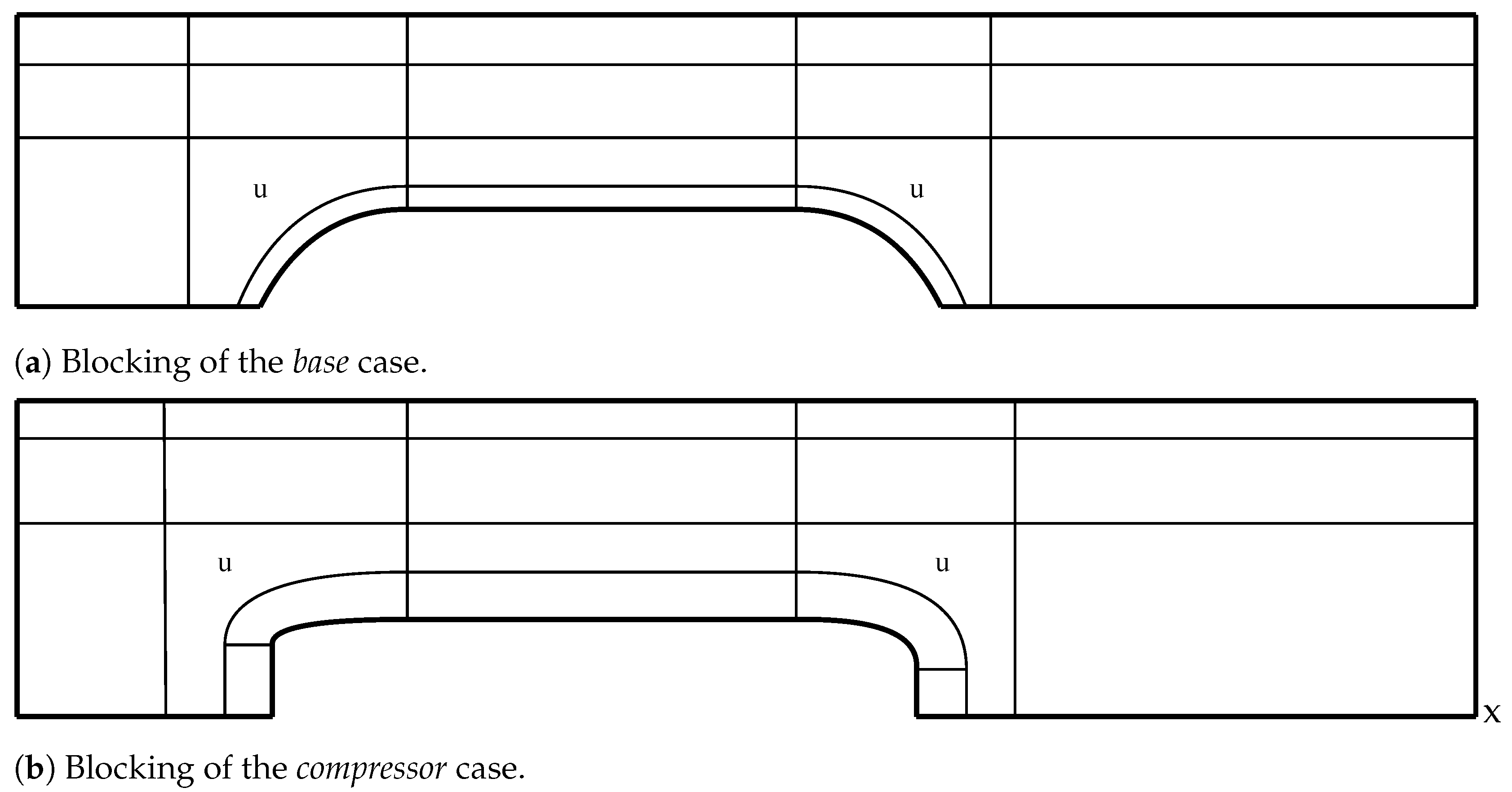
The mesh employed is a hybrid mesh formed using the blocks shown in
Figure 3. All of the blocks are structured, apart from the two unstructured, marked with a
u. These blocks are used to adapt the boundary layer mesh to the near field domain, avoiding bad quality elements, as discussed at the end of this section. These unstructured regions use mainly quadrilateral elements.
A mesh sensibility study was conducted for the
base case in [
15]. The chosen mesh from that study had 171,947 elements for the largest blockage ratio (0.75). The mesh employed in [
12] for the same geometry and speed had 77,000 elements. As the mesh parameters are equal in the
base and
compressor cases, a new mesh sensibility study has not been conducted for this work.
Regarding these parameters, the boundary layer on the tube wall has been set as a geometric progression using a first element height of m, a progression ratio of 1.25, and 38 layers. For the boundary layer on the capsule, the resolution is increased, using a first layer height of m, a geometric ratio of 1.2, and 58 layers. These prism layers allow obtaining a on the vehicle wall and on the tube wall.
The capsule boundary-layer geometric progression is maintained until the normal distance to the wall (horizontal or vertical) is 0.37 m, which implies that the largest element on the unstructured region is 1.75 times larger than the last element height on the boundary layer. Then, the space between the two boundary layers has used a linear progression that ensures the same spacing on the border elements between blocks.
The mesh size on the compressor, turbine, and front and rear faces of the vehicle have a uniform spacing, equal to the last boundary layer height (0.0326 m). On the channel, a bigeometric progression is imposed, using a geometric ratio of 1.05 for both ends.
To avoid wave reflection, a large element size is imposed near inlet and outlet boundaries. These elements are the results of imposing a geometric progression from the end of the unstructured block to the inlet and outlet boundaries. The growth ratio is 1.012 with 400 layers upstream, and 1.006 with 700 layers downstream.
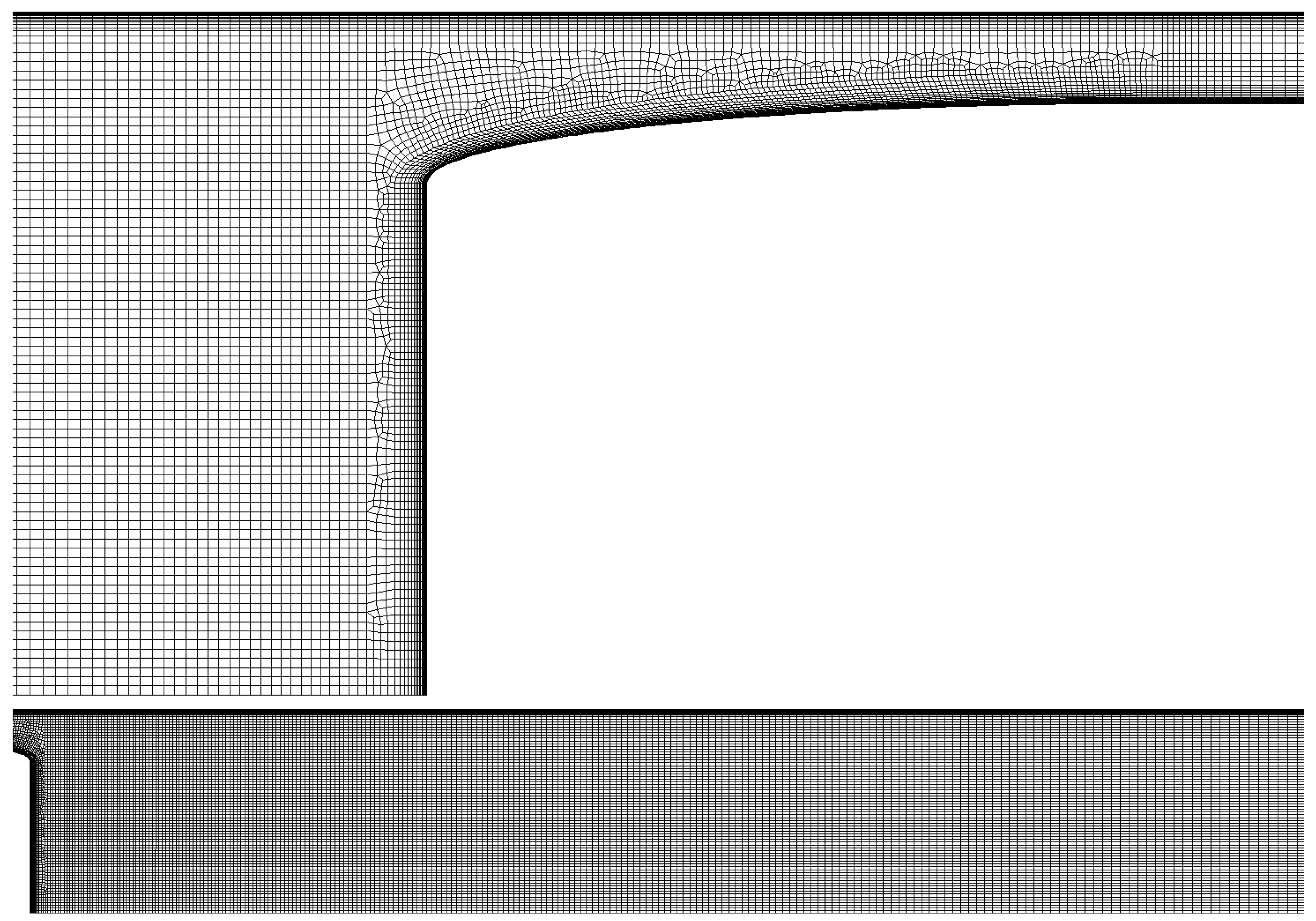
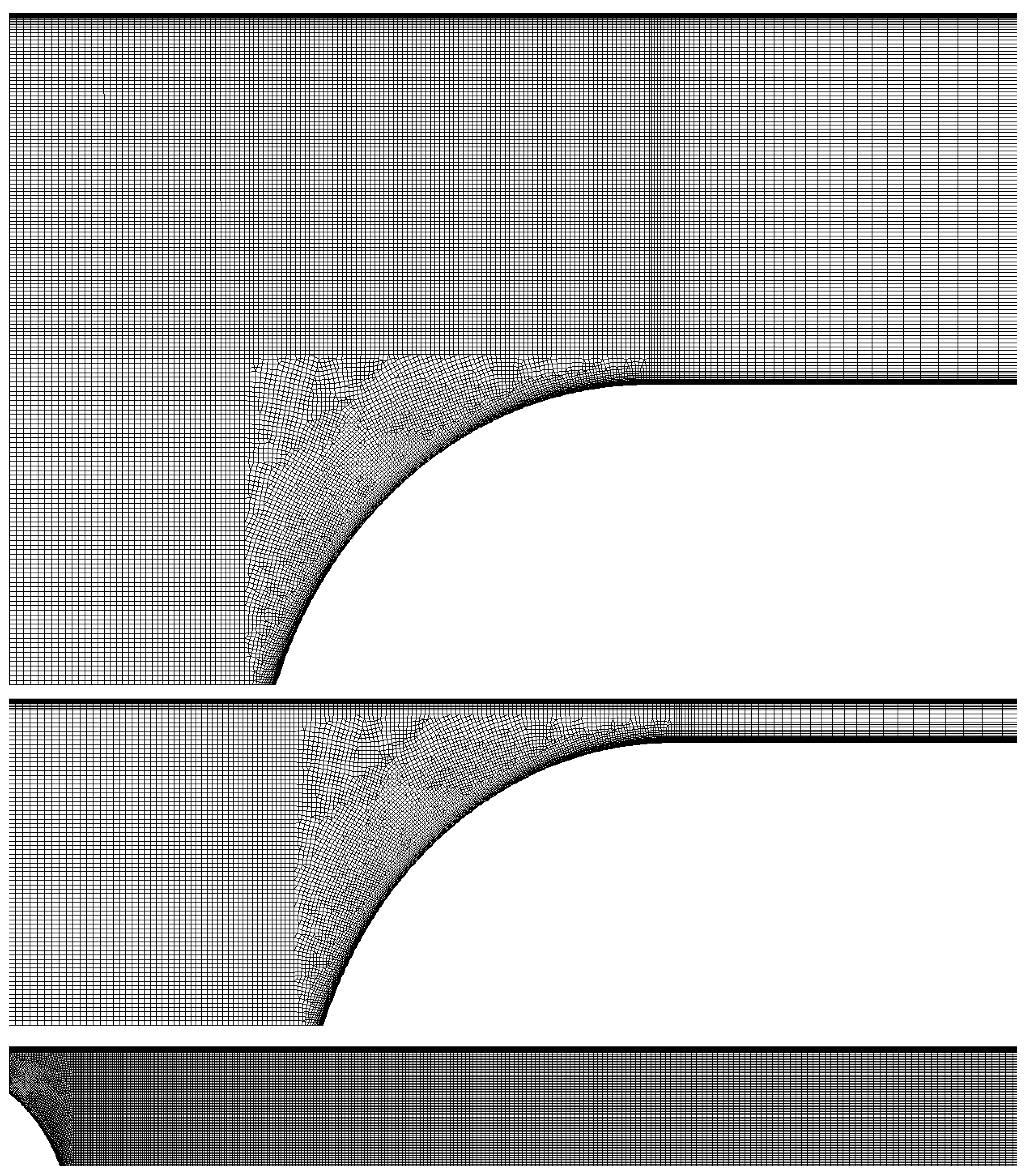
Using the mesh parameters already described, the meshes for the different blockage ratios are obtained. They are shown in
Figure 4 for the
compressor case and in
Figure 5 for the
base. Note that both cases are equivalent in terms of element size and distribution. The captures are taken for the case of
, as it is considered to be the most restrictive due to the proximity of both boundary layers. For the first case, a capture for
is also provided to better show how the channel between the vehicle and the tube has been discretized.
The quality and number of elements for each mesh are collected in
Table 1. The quality is always above 0.37 for the
base case, and above 0.33 for the
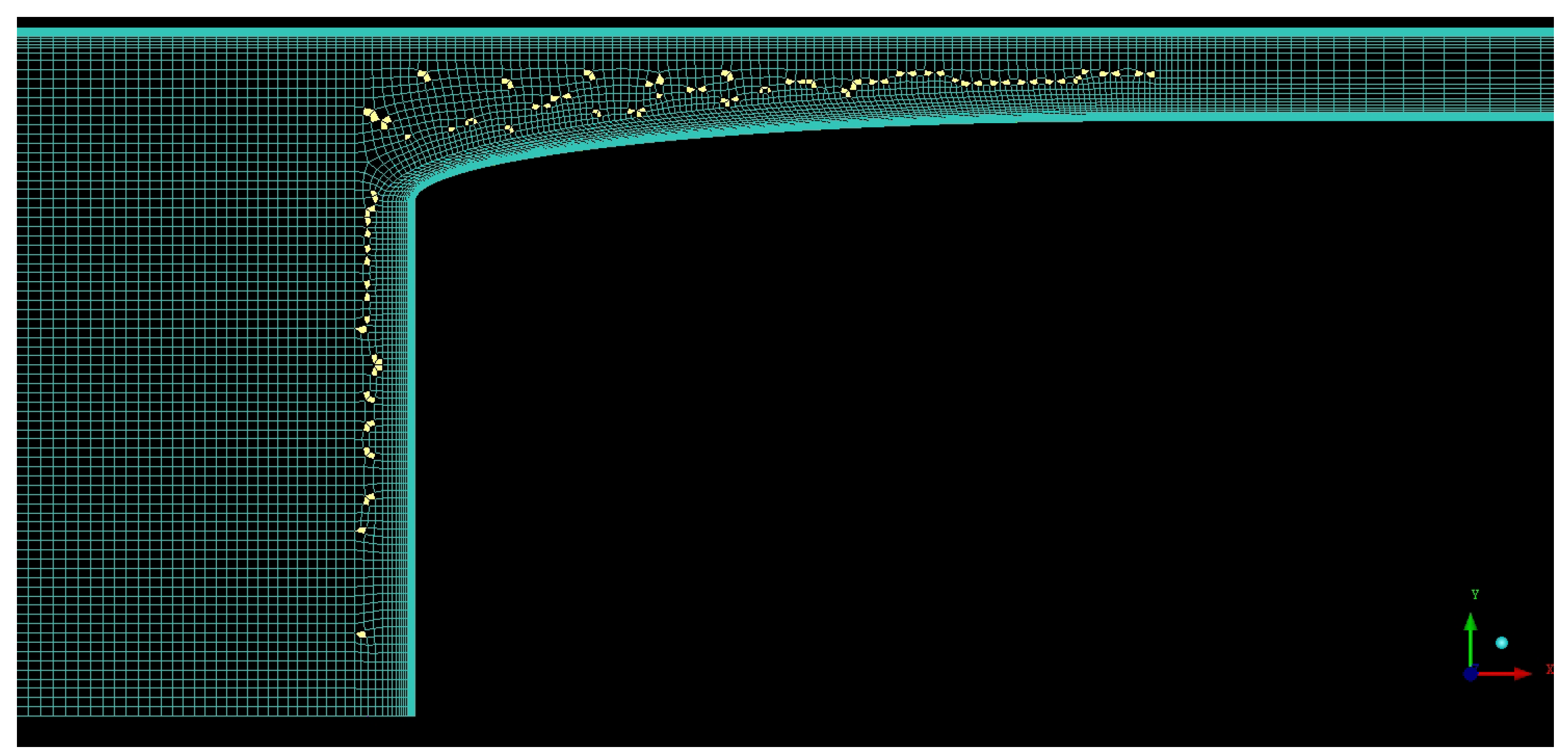
compressor case. Moreover, only 1 element has a quality below 0.4 for the first case and only 20 (around 0.01%) for the second case. To better show what this implies for the actual mesh,
Figure 6 represents the worse quality elements for the
compressor case, whose quality is slightly lower. These elements are mainly near the border between the structured and unstructured blocks, as the mesh has to transition from the boundary layer size to the near field size.
2.4. Set Up
The simulation was conducted using a 2D axisymmetric model to reduce the computational cost, maintaining the accuracy of the results. The rotation axis is the
axis line shown in
Figure 1 and
Figure 2. Previous studies also used this hypothesis for both trains at atmospheric pressure [
7] and at low pressure [
12,
17,
23].
Some authors also compared the accuracy of their results using a 3D and a 2D axisymmetric model. Ehrendorfer et al. [
6] compared the 2D model with experimental results at real scale and atmospheric pressure, concluding that the wave problems were properly reproduced. Li and Yuangui [
30] performed a similar experiment in 2017, focusing on the transonic entrance of a train in a tunnel with the 2D model. For lower pressures, Oh et al. [
14] compared simulations for a sphere, concluding that, at transonic speeds, the maximum error on the drag was about 4%.
Regarding the thermodynamic parameters, both the specific heat ratio
and ideal gas constant for the air
R are considered invariant with the pressure. Regarding the viscosity, the Sutherland model has been used as in [
9,
12,
14].
The scheme employed is a second-order spatial discretisation, using
SST model as turbulence model as used in [
14]. Kim et al. in [
12] compared the results for different turbulence models, including
SST,
, Spalart-Allmaras, and a laminar case for the same
base scenario presented in this work. They reported less than 4% of difference among all the models simulated.
Furthermore, Morden et al. in [
31] conducted a comparison of the different turbulence models concerning experimental results of train aerodynamics. They concluded that the
SST model provided the best surface pressure among the available RANS models.
The solver is compressible pressure-based. A Riemann solver has been also tested, whose results are shown in
Section 3.1.
Regarding the steadiness of the case, a steady solver has been selected to reduce the computational cost, as only time-averaged values are to be obtained. An unsteady simulation has also been performed to check the validity of this hypothesis, whose results are shown in
Section 3.1. The use of a steady solver is valid since wave propagation, which was not studied, is a time-dependent effect. Only steady-state values for the drag and thrust need to be computed.
The different boundaries conditions on the domain, marked in
Figure 1 and
Figure 2, are as follows:
Inlet: the mass flow and the total temperature are imposed. Both are based on the capsule speed , reference pressure , static temperature , and the tunnel area :
Tube: moving and adiabatic wall. The speed on the wall is equal to the speed of the capsule, , in a ground reference frame.
Outlet: pressure outlet, set to the same pressure as the reference pressure of the tube .
Vehicle: static and adiabatic wall.
Axis: rotation axis to convert the 2D domain into an axisymmetric one.
Nozzle: mass flow inlet. The mass flow is imposed such that the turbomachinery swallows
, and the total temperature at the nozzle exit is
. The value chosen for both variables is discussed in
Section 2.6.
Compressor: pressure outlet, modifying the pressure until the mass flow set on the nozzle is obtained.
The values taken by the different variables are listed below:
Reference speed
: 500 km/h (current limit for Transrapid [
29]) and 700 km/h (higher speed considered for hyperloop);
Reference pressure : 0.1 atm;
Blockage ratio : from 0.2 to 0.75;
Reference temperature
: 288.15 K, same as in [
12];
Turbulence intensity: 5%.
The size of the tunnel is computed using a range for the blockage ratio. The lower limit is based on current HSR tunnels and is 0.23 [
32,
33]. Other studies used similar values such us 0.2 in [
9] and 0.28 in [
20]. The top blockage ratio has been chosen as 0.75 because, at this value, the boundary layer of the tunnel and the capsule nearly collapse.
Regarding the selected pressure, although in the previous work by the present authors, 0.01 atm, 0.1 atm, and 1 atm were studied; only 0.1 atm is used in this paper. This is the expected pressure at which a hyperloop installing a compressor could work, and it is also the value used by other authors in their ETT studies, such as Bao et al. [
20] and Swissmetro [
4]. Zhang et al. [
9] used a similar figure, namely 0.2 atm.
The solver used for this case is ANSYS Fluent.
2.5. Inlet Boundary Condition
Concerns about the choice of the boundary condition at the inlet exist due to the simplification of the problem. This issue was analyzed in a previous work conducted by the present authors [
15]. In that study, it was concluded that the value of the drag is highly dependent on the upstream boundary condition. Two different boundary conditions were analyzed, total pressure inlet and mass flow inlet, reporting large differences between them.
In the real case, due to the wave propagation inside a tube, the upstream thermodynamic conditions vary continuously. The consequence is that the drag is not only a function of the actual speed of the capsule , but also of the position of the train inside the tunnel, how fast this speed has been reached, and where the boundary conditions are placed (i.e., tube walls, another vehicle, changes on the tube size...). This effect cannot be reproduced with the current simplification of the problem and makes it not possible to set a constant value for the inlet boundary.
As a representative average result, the boundary condition chosen at the inlet is imposing the mass flow. This condition is reported to be the most restrictive, and it represents the case in which all the mass flow passes through the channel between the tunnel and the train. This is considered by the authors to be the design point of hyperloop to avoid air compression in front of the capsules, which would considerably increase the drag on a route. As reported in [
15], if the total pressure is imposed, the mass flow that should pass through the vehicle may not be guaranteed.
This is a relevant difference to an open tunnel. While, in a closed tube, if the required air does not pass around the vehicle it ends up being compressed in the front, with open ends, this displaced air could exit the domain without being compressed.
However, the inlet boundary condition is not the only factor that affects the flow behavior upstream. If too much mass flow is imposed on the inlet, it reaches what is known as the Kantrowitz limit [
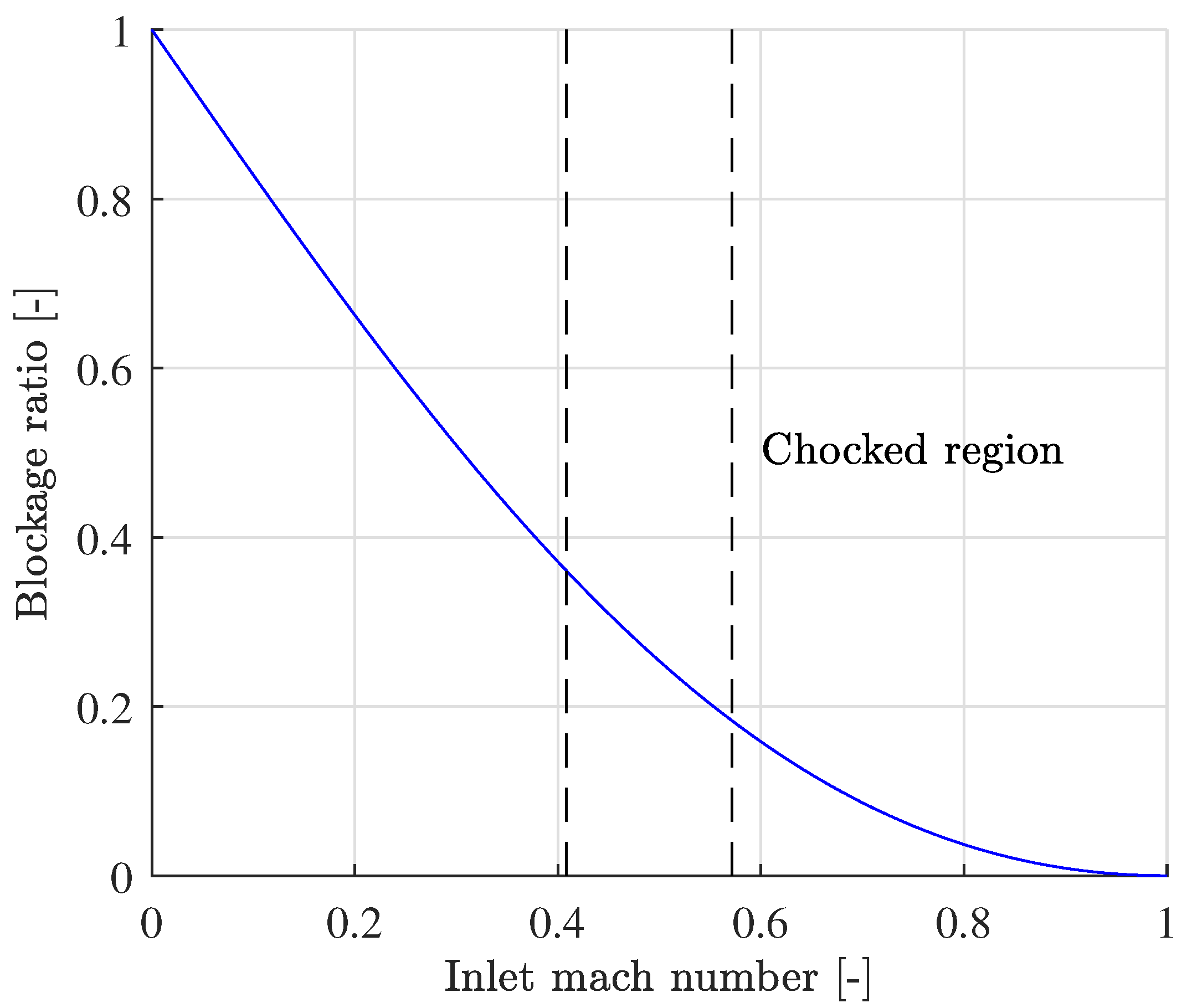
34]. This limit occurs when the flow reaches sonic conditions (Mach equal to 1) on the smaller cross-sectional area, which is the passage between the tunnel and the capsule. Using an isentropic 1D simplification, the Kantrowitz limit leaves a 2D space in the plane (
,
) in which the flow is not blocked and all the mass flow can pass around the capsule without increasing its far field pressure. This solution space is shown in
Figure 7.
The Mach number where the Kantrowitz limit is achieved is known as the critical Mach number. Beyond this value, if the physical mass flow is imposed, the pressure has to increase over
and speed has to decrease under
to maintain the inlet corrected mass flow. This effect will be discussed in
Section 4 alongside the results. There, it will be proved how the addition of a compressor mitigates the induced effects.
It is important to remark that for the geometries without compressor, at 700 km/h, all the blockage ratios are above the Kantrowitz limit, as the limit is
; and for 500 km/h, the limit is
. For the
compressor case, the blockage ratio that reaches this limit is discussed in
Section 4, as it cannot be analytically obtained.
2.6. Specific Set Up for the Compressor and Nozzle
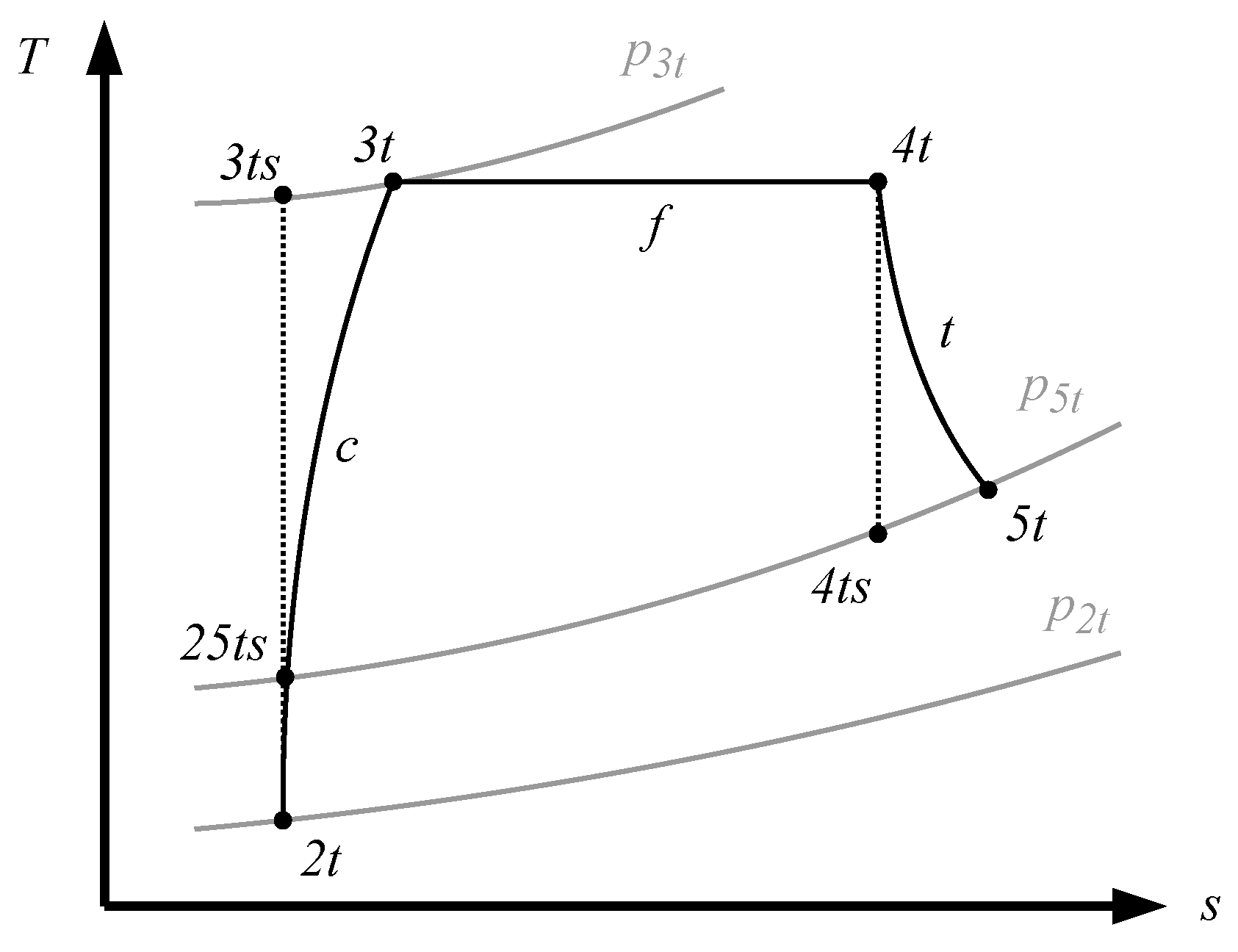
This case has two additional degrees of freedom: the internal mass flow , directly imposed on the compressor and nozzle boundary conditions; and the specific power transmitted to the flow, imposed on the nozzle through the total temperature . Both are varied in order to meet the following specifications:
The fact that the value for the isentropic efficiency is so low can be explained due to its definition. This parameter tries to collect in one number all the processes that occur inside the hyperloop capsule and, for simplicity, are not modeled in this work. These are the flow compression on the turbomachinery, internal ducting, and flow expansion on a turbine and a nozzle. All the inefficiencies of these three processes are included in .
The
diagram shown in
Figure 8 represents thermodynamically what is occurring to the non-modeled flow and helps to understand the definition of the efficiency. In this figure, the three evolutions shown are:
Intake and compressor (c): from 2 to 3.
Internal ducting (f): from 3 to 4.
Turbine and nozzle (t): from 4 to 5.
With these values in mind, the isentropic efficiency is defined as follows:
where
is the total pressure ratio on the compressor and the nozzle.
It is not the purpose of the authors to further detail what occurs to the internal flow or to optimize this efficiency. The only purpose of this definition is to have a way to measure the non-modeled flow and ensure equality among the different cases.
Having said that, the values obtained for the compressor and nozzle boundary conditions that match the prescribed net thrust and efficiency are collected in
Table 2.
2.7. Knudsen Number
It is important to check that the continuum medium hypothesis is still valid for the most restrictive case, 0.01 atm; otherwise the Navier-Stokes equations cannot be used. For that purpose, the Knudsen number
is computed to ensure that is lower than 0.01 [
17]. This number is defined as:
where:
L: characteristic length, based on capsule length
m, as in [
26].
P: operating pressure, using atm.
T: operating temperature, using K.
: Boltzmann constant.
d: characteristic particle length, which is taken as the hard diameter of the
molecule, which is
[
35].
For the present case, this value is , which means the continuous medium hypothesis is valid. It would be also valid for pressure values as low as atm, which are out of scope for this application.
4. Discussion
The discussion section is based on comparing the performance of the base and compressor cases. For this purpose, the drag cannot be used and a new variable needs to be employed, which is the input power.
When the compressor is not installed and the train is a completely closed body, the aerodynamic resistance is a variable representative of the performance of the vehicle. However, in the
compressor case, the capsule is not a closed body, and part of the flow is allowed to go through it, increasing its energy internally thanks to the turbomachinery. In this scenario, the drag and the thrust have no physical meaning if computed separately, and only the net thrust can be obtained. The net thrust is not a variable comparable to the drag of the first case. Note that the former has to be equal to zero for the comparison, as discussed in
Section 2.6.
The definition of the power takes into account the required energy per time unit that maintains the vehicle speed; on the base case to overcome the drag, and in the compressor case to reach a zero net thrust level. Thus, the power is computed differently depending on the case:
Base case: the mechanical power transmitted to the vehicle: .
Compressor case: the aerodynamic power the compressor transmits to the fluid: .
Note that none of the cases consider the efficiency, which means that the electric machine that drives the system must have higher power. This is a strong simplification, as the base case is typically driven by a linear motor, whose electromechanical efficiency is considerably lower than the one of a rotatory motor driving the compressor.
Once it is clear how the power has been defined, in
Figure 10, the required power for the
base and
compressor cases is compared. The main conclusion is that, while for low blockage ratios the difference is not important, for higher ones, it is beneficial to use a compressor to minimize the required energy for both 500 km/h and 700 km/h.
From the same figure note that, for the base case, the slope of the curve at 700 km/h increases exponentially for all the BR, as the Kantrowitz limit has been surpassed from . When the reference speed is decreased to 500 km/h, this exponential growth also starts to occur from the same limit, set at . In the case of installing the compressor, the slope of both curves is considerably lower, especially at 500 km/h, when the Kantrowitz limit is never reached.
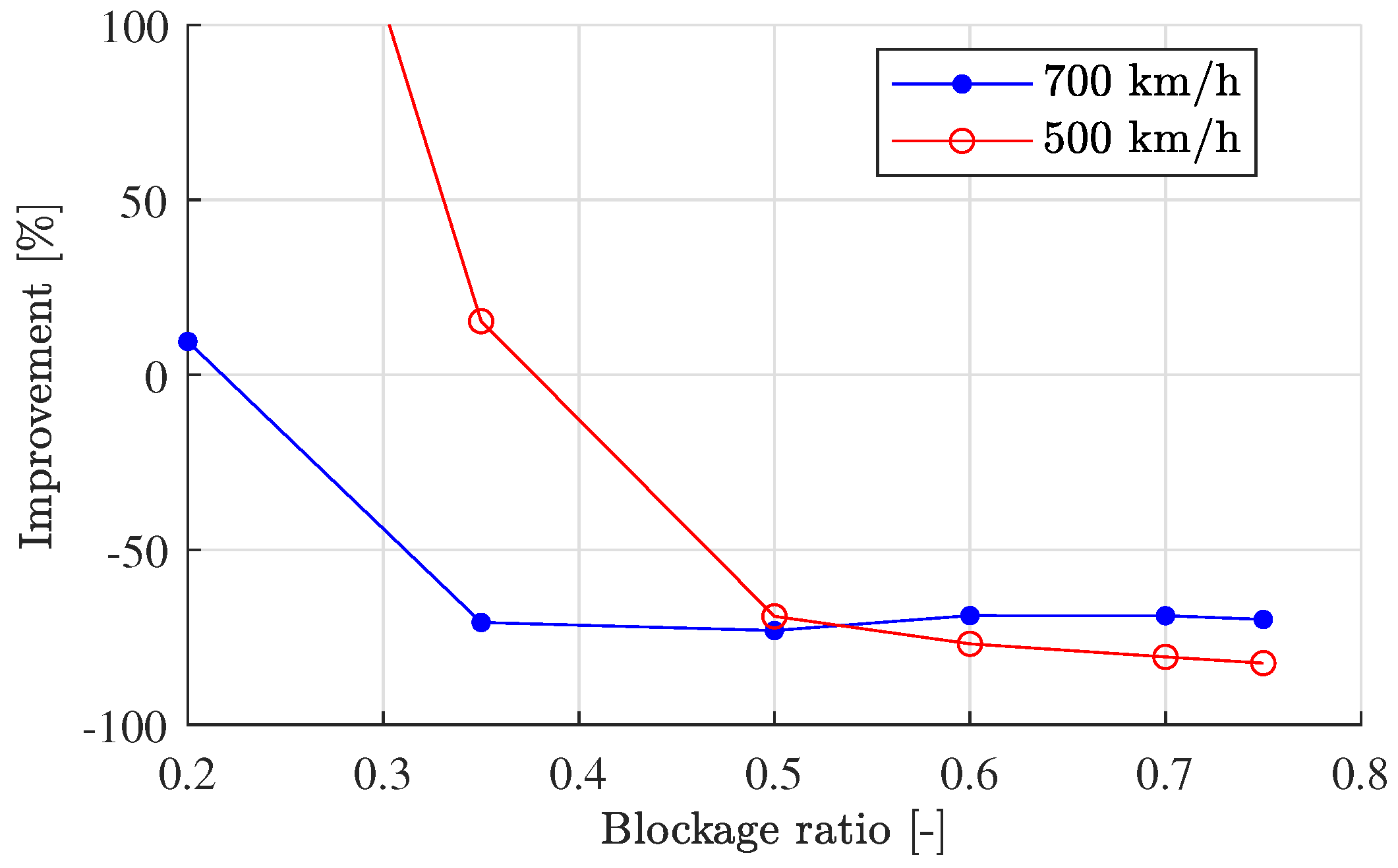
The actual percentage at which the
compressor case improves is represented in
Figure 11. Note that for low blockage ratios, the compressor does not work properly (even worse for 500 km/h), but for high blockage ratios, the power consumption is around 70 % lower than for the
base case. Both curves decrease asymptotically to a certain value, from which the relative improvement of the compressor is constant.
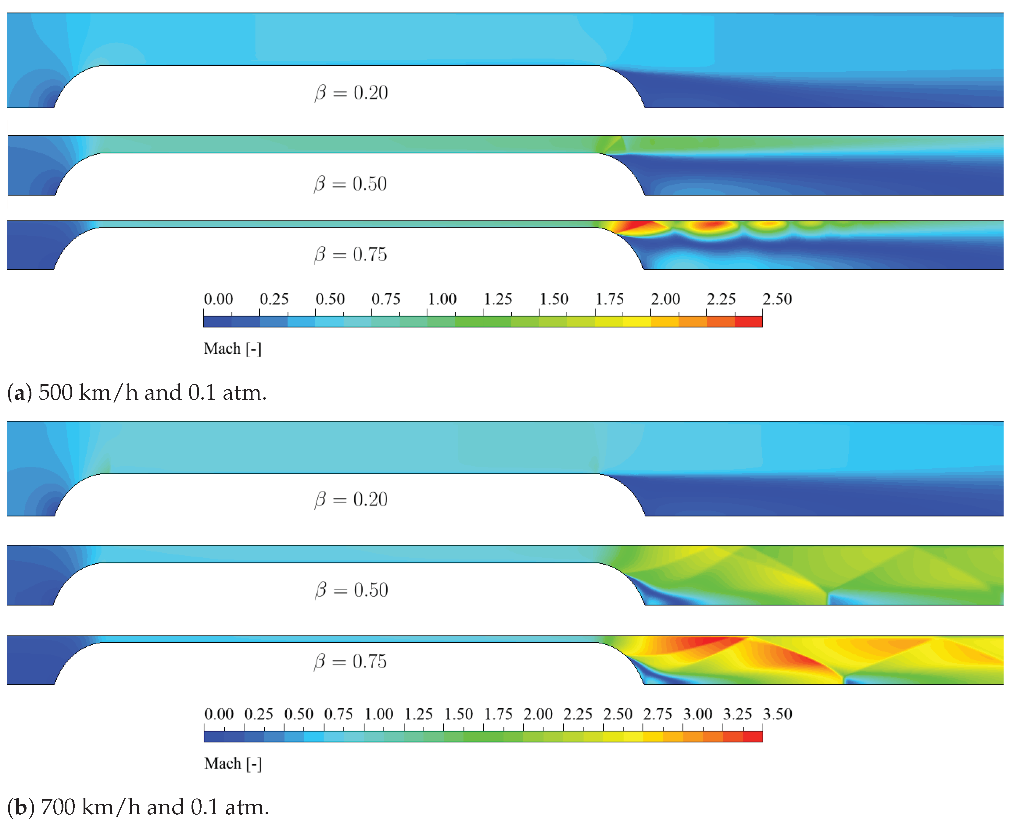
The compressor bases its improvement on delaying the transonic effects. Thus, the shock waves present in
Figure 9 occur at higher speeds, as shown in
Figure 12, and the induced pressure and speed upstream the capsule are mitigated, as shown in
Figure 13. These effects, as they appear at high blockage ratios, explain why the improvement of the compressor is more significant in this region.
Thus, the power reduction can be better explained by analyzing the flow patterns. This is why in
Figure 12, the Mach contours for the
base and
compressor cases are compared for different blockage ratios at the largest simulated speed, 700 km/h.
For
,
Figure 12a shows no shock waves in any of the cases. However, the acceleration of the flow on the passage is more significant for the
base case. Here, the improvement in the case is not due to the avoidance of transonic effects, but regarding the mitigation of the downstream subsonic separation.
For
and
in
Figure 12b,c respectively, the flow behavior is equivalent. For the
base case, the flow is so accelerated on the channel that obliques shock waves appear. These waves disappear when the compressor is installed, explaining why the required power is considerably reduced.
For
and
, the flow on the
compressor case is subsonic everywhere, as these cases are operating under the Kantrowitz limit (see
Figure 14). For
,
Figure 12c shows that Mach numbers greater than 1 are locally reached, but shock waves are still avoided.
It is important to remark that the flow patterns with the compressor are more uniform among the cases. Qualitatively, they are not affected by the size of the tunnel.
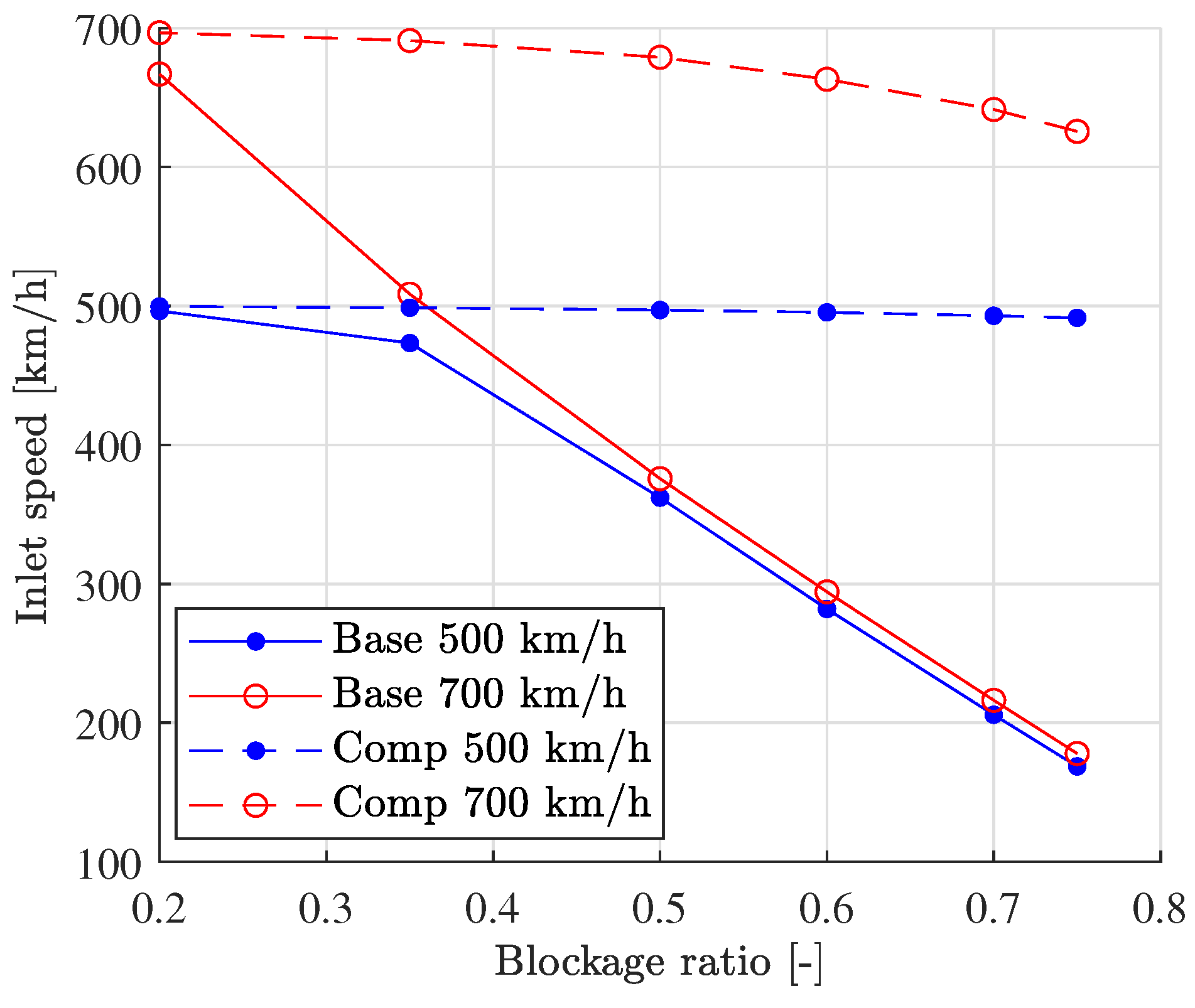
On the other hand, the effect on the induced speed is shown in
Figure 13, where the actual inlet speed from the simulation is plotted against the blockage ratio for different reference speeds. Note that the
compressor case, especially at 500 km/h, can maintain the capsule speed at the inlet. However, for the
base case, the upstream pressure increase does not allow the inlet speed to be maintained, which decreases linearly with the blockage ratio.
Note that induced speed is nearly the same for the base case for both reference speeds, as this effect is mainly dependent on the geometry.
Not only the mitigation of the shock waves, but the fact that the induced speed for the compressor case is considerably lower is also an indicator of the improvement present in this case.
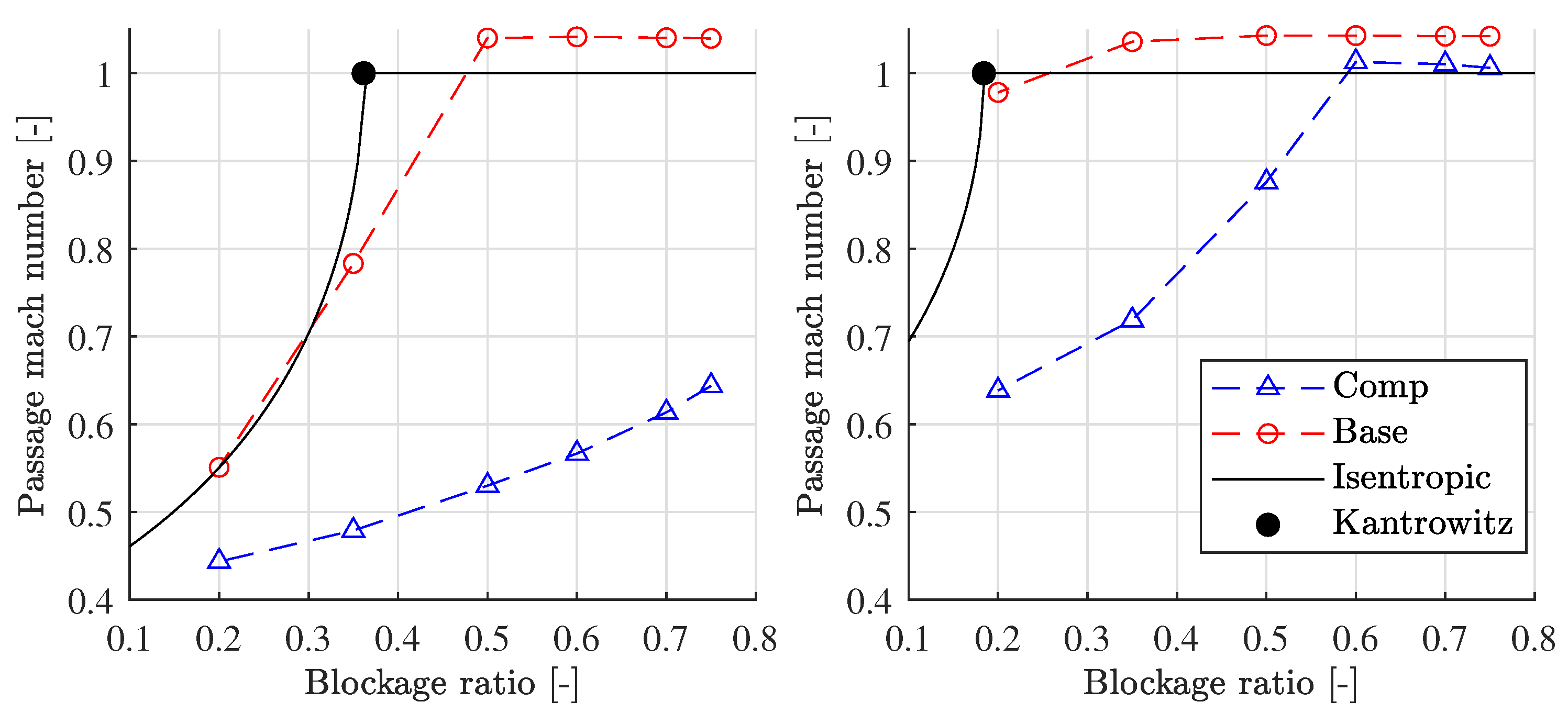
Then, we analyzed how far each of the cases is from reaching the Kantrowitz limit. This is evaluated by computing the Mach number at the end of the passage between the capsule and the tunnel, which is the throat for these cases. Thus, it is the location where sonic speeds are firstly reached. This is represented in
Figure 14, for each reference speed and BR. Not only from CFD, but the isentropic Mach number
M is also obtained, computed using the compressible mass flow equation, comparable to the
base case:
It can be seen that for 700 km/h and no compressor, the capsule always operates above the Kantrowitz limit, which is what the operator wants to avoid. As previously mentioned, the limit is 0.18 according to the analytic approximation. In this scenario, quite big tunnels (BR less than 0.2) have to be used, which is a BR even lower than for HSR (0.23). For 500 km/h, the Kantrowitz limit occurs at 0.36, which is also not a particularly high value.
The use of a compressor increases considerably these limits, allowing full BR operation at 500 km/h, and limiting the operation to tunnels of or lower blockage ratios for 700 km/h.
The analytical approximation follows closely the trend of the
base case. However, it is required to have more CFD points to accurately reproduce the exact BR where sonic conditions are reached. Note that, although the analytical approximation outputs a Mach equal to 1 on the throat, the CFD value is slightly higher than 1. This was also reported by Lijo et al. in [
36] after conducting some experiments for a Poiseuille flow in a pipe.
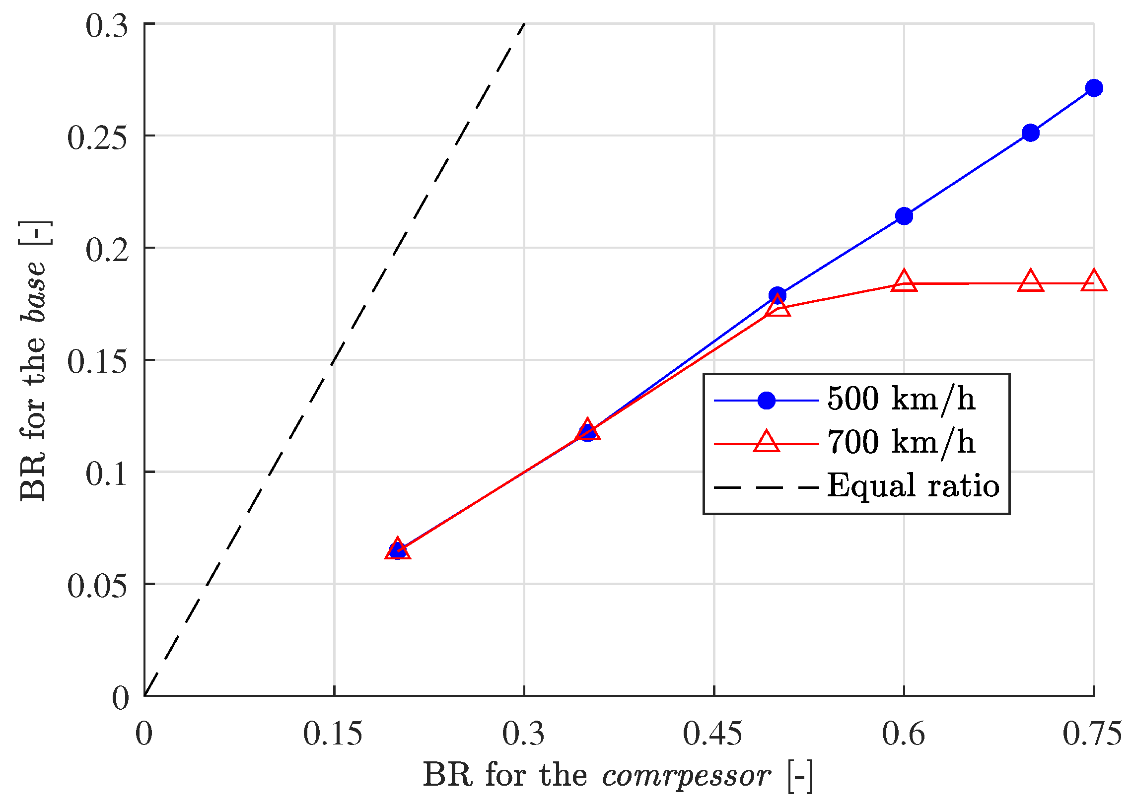
To better analyze how the addition of a compressor improves the performance of the capsule in terms of transonic effects, the equivalent blockage ratio among the two cases is represented in
Figure 15. This value has been obtained from the CFD curves shown in
Figure 14, making both passage Mach numbers equal.
From the plotted data, one can conclude again that the installation of a compressor allows the use of smaller tunnels if the same blockage is to be achieved, which implies a higher BR when using turbomachinery. In addition, note that the trend is linear for 500 km/h and also for 700 km/h until the Kantrowitz limit is achieved for the compressor case (BR between 0.5 and 0.6).
Due to this linearity, until the choke of the flow occurs, the following regression, independent of the speed, can be assumed:
This relation indicates that the BR of the tunnel can be 2.8 times higher when installing a compressor on the vehicle. In terms of physical parameters, this means that, for the same vehicle cross-section, the area of the tube can be 2.8 lower with aerodynamic propulsion.
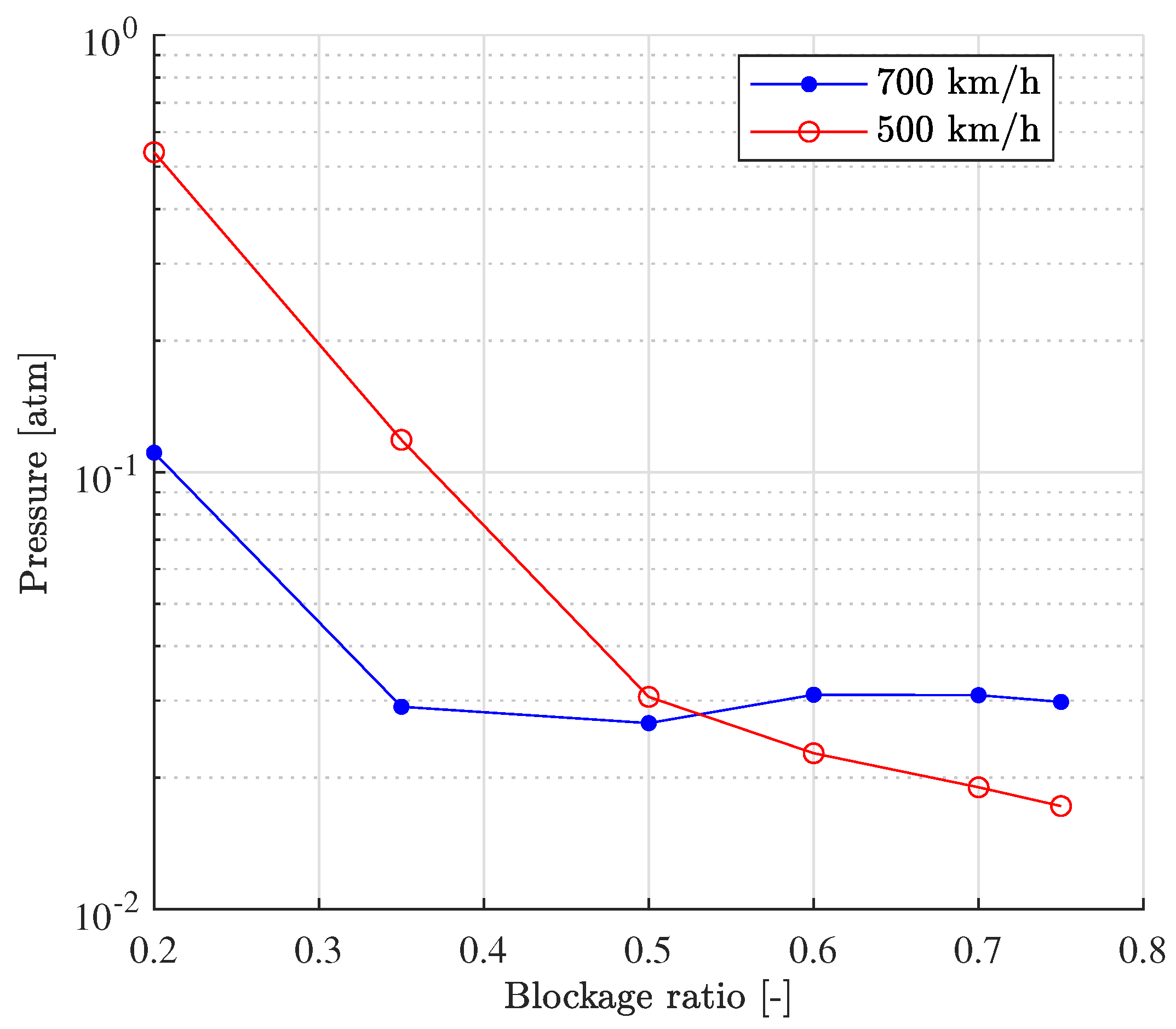
The final study that was conducted was to obtain the pressure for the
base case that matches the same power consumption as the
compressor one, using data from [
15]. To do this, a linear relation of the drag with the pressure must be assumed. This trend was reported not only by the present authors in [
15], but also by Liu et al. in [
17].
Having said that, the results of this study are shown in
Figure 16. For medium or high blockage ratios, 0.02 atm at 500 km/h and 0.03 atm at 700 km/h is required to get the same performance. In terms of the real system, this fact implies an increase in the complexity and hazard of the case without a compressor.
5. Conclusions
After comparing the thermodynamic behavior of a capsule inside a low-pressure tunnel using and not using a compressor, the conclusions can be presented.
The addition of the compressor to the simulation leads to a reduction in the required power to maintain a constant speed for high blockage ratios. At low BRs (around 0.2), it can even be beneficial to avoid using the compressor, as the flow is entirely subsonic. However, as the tunnel gets smaller and transonic and supersonic effects start to appear, the power consumed by the base case grows exponentially. In those cases, the compressor consumes considerably less power. This reduction grows asymptotically to a value around 70% at a BR between 0.35 and 0.5. Higher blockage ratios do not increase the improvement of the compressor.
The capsule and the tunnel behave similarly to a converging-diverging nozzle, in which, once critical conditions are reached, the flow becomes supersonic downstream, enforcing the appearance of obliques shock waves. The analysis of the flow patterns has shown that the addition of the compressor can remove these waves of the vehicle in all of the simulated cases, even if they reach sonic conditions. Thus, the flow is qualitatively independent of the size of the tunnel.
Not only is the mitigation of shock waves an effect of the turbomachinery, but also, for the geometry studied, the downstream separation is removed due to the nozzle that substitutes the wall at the tail of the capsule.
The delay in the transonic effects is also evident when analyzing the induced speed present on the inlet of the domain. The compressor case can maintain the inlet speed equal to the capsule speed, especially at 500 km/h, as the case is always below the Kantrowitz limit. For higher speeds, the induced speed is still negligible compared to the base case, in which the induced effect increases linearly with the BR independently of the reference speed. This is because this effect is mainly dependent on the geometry.
The benefits of the installation of the compressor can also be evaluated in terms of the point at which the critical Mach number is reached. The turbomachinery enables the vehicle to operate subsonic in a wider range, which is what explains the reduction in power consumption. For the base case, for 700 km/h, the limit is at , while with the compressor it is increased somewhere in between 0.5 and 0.6. It is important to remember that the reference value of the blockage ratio for an HSR is 0.23, which means that a conventional train will operate above the Kantrowitz limit if running at this speed. With regard to 500 km/h, the base case blocks at , while the compressor never does in the range studied. Moreover, it is remarkable how the isentropic approximation follows accurately the trend of the CFD simulation when evaluating the Mach number on the passage, although a Mach number slightly greater than 1 have been achieved on the throat.
In that sense, an equivalent tube has been compared between both cases. The main conclusion is that, until the compressor case blocks, it can operate with tunnels of 2.8 times lower cross-sectional area for the same capsule section, independently of the speed. This is a considerable reduction on the tunnel size, and so, on the infrastructure cost.
If future ground transport is to overcome 500 km/h, a new concept where ambient pressure can be decreased must be proposed. This allows decreasing the drag of the capsuled linearly with this parameter, leading to acceptable air resistance even at very high speeds and small tunnels. Moreover, the system performance improves considerably when installing a compressor on the vehicle due to the power consumption reduction and the chance to use considerably smaller tunnels.


