
Graphical and Analytical Quantitative Comparison in the Domes Assessment: The Case of San Francesco di Paola


 ,
,  ,
, 
Abstract
1. Introduction
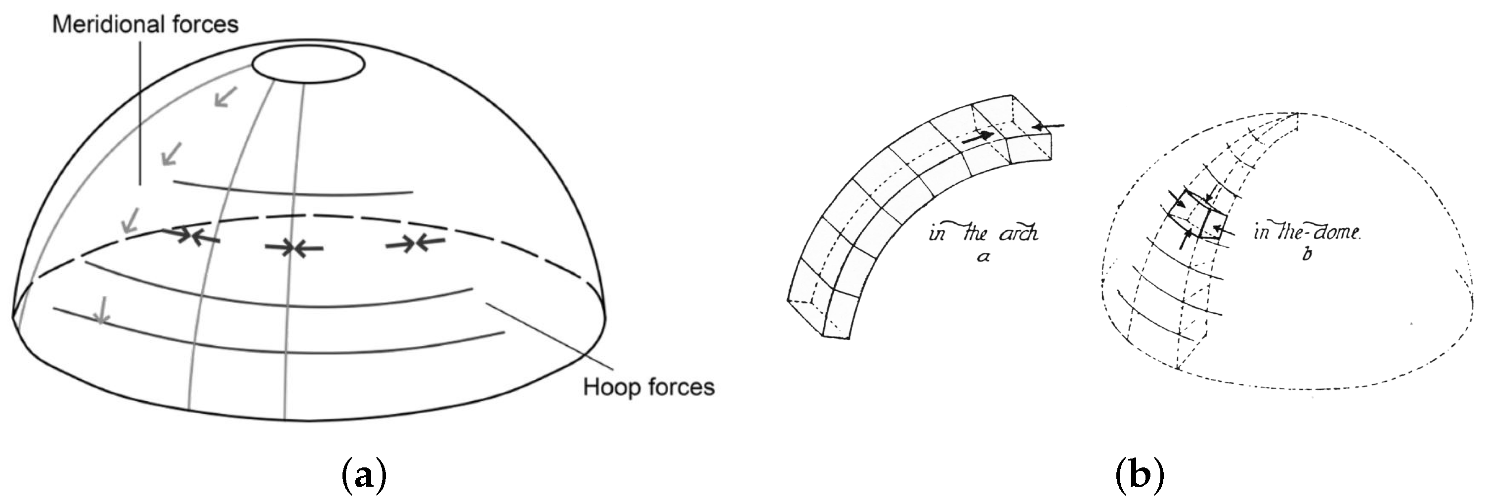
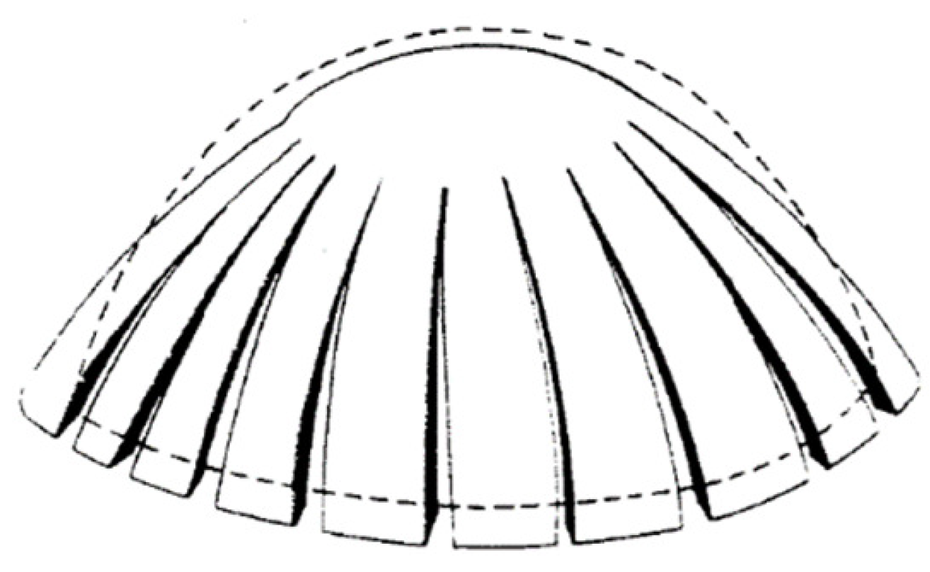
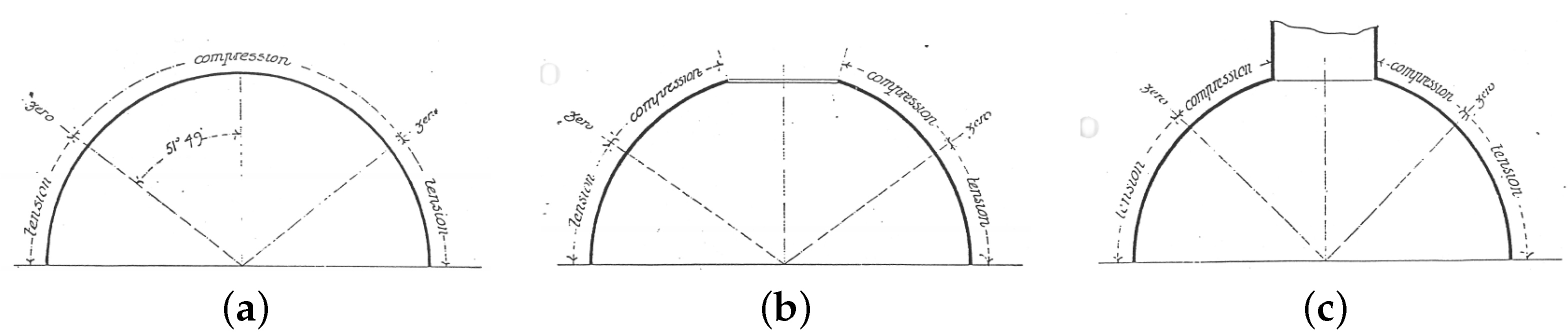
2. Mechanical Behavior of Masonry Domes
Evolution of Classical Methods for Assessing the Stability of Vaults and Dome
3. Problem Statement
3.1. A Few Initial Remarks
3.2. Previous Applications of the Methods
3.3. Materials and Methods
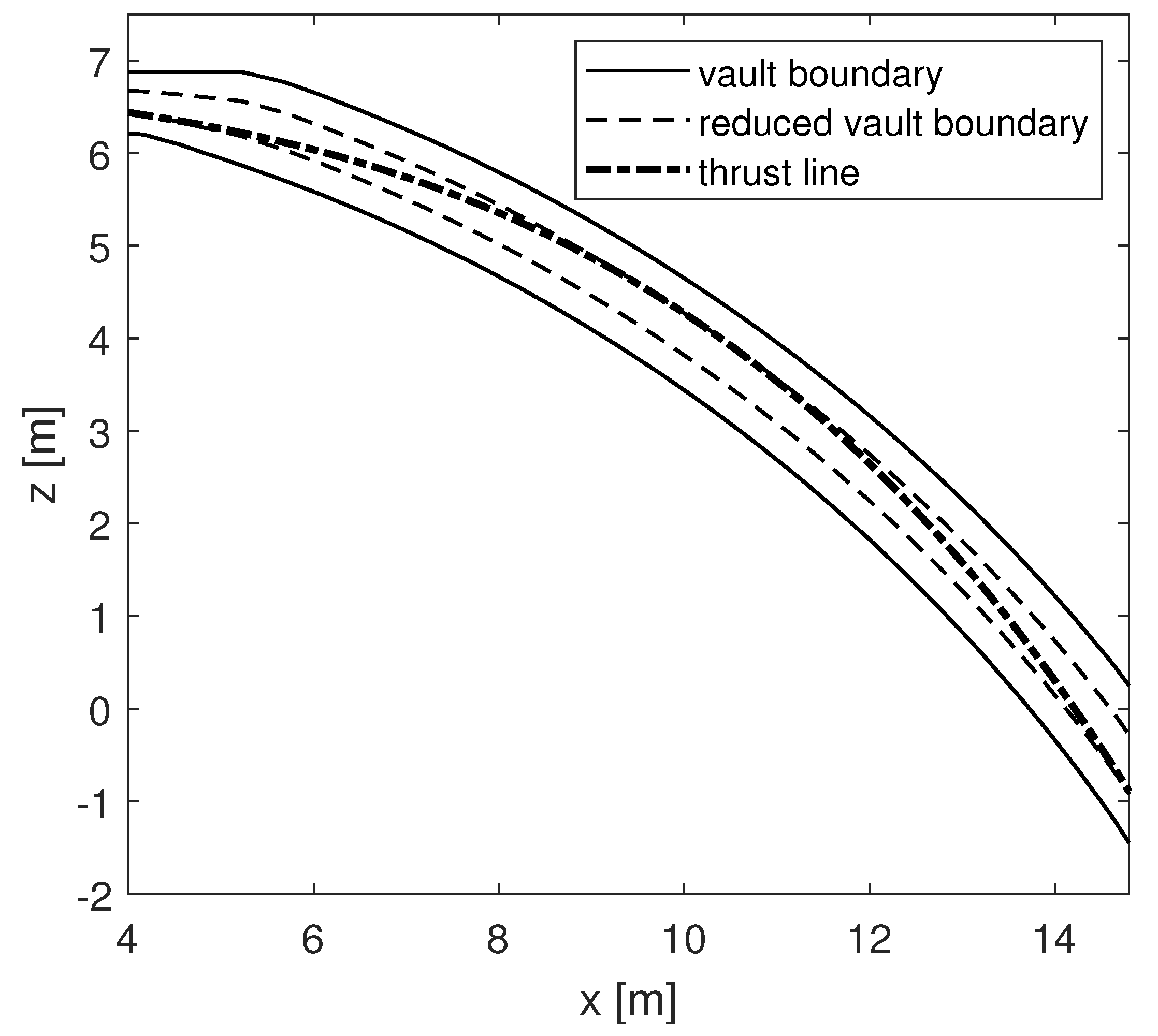
3.3.1. Thrust Line Analysis
3.3.2. Modified Thrust Line Method
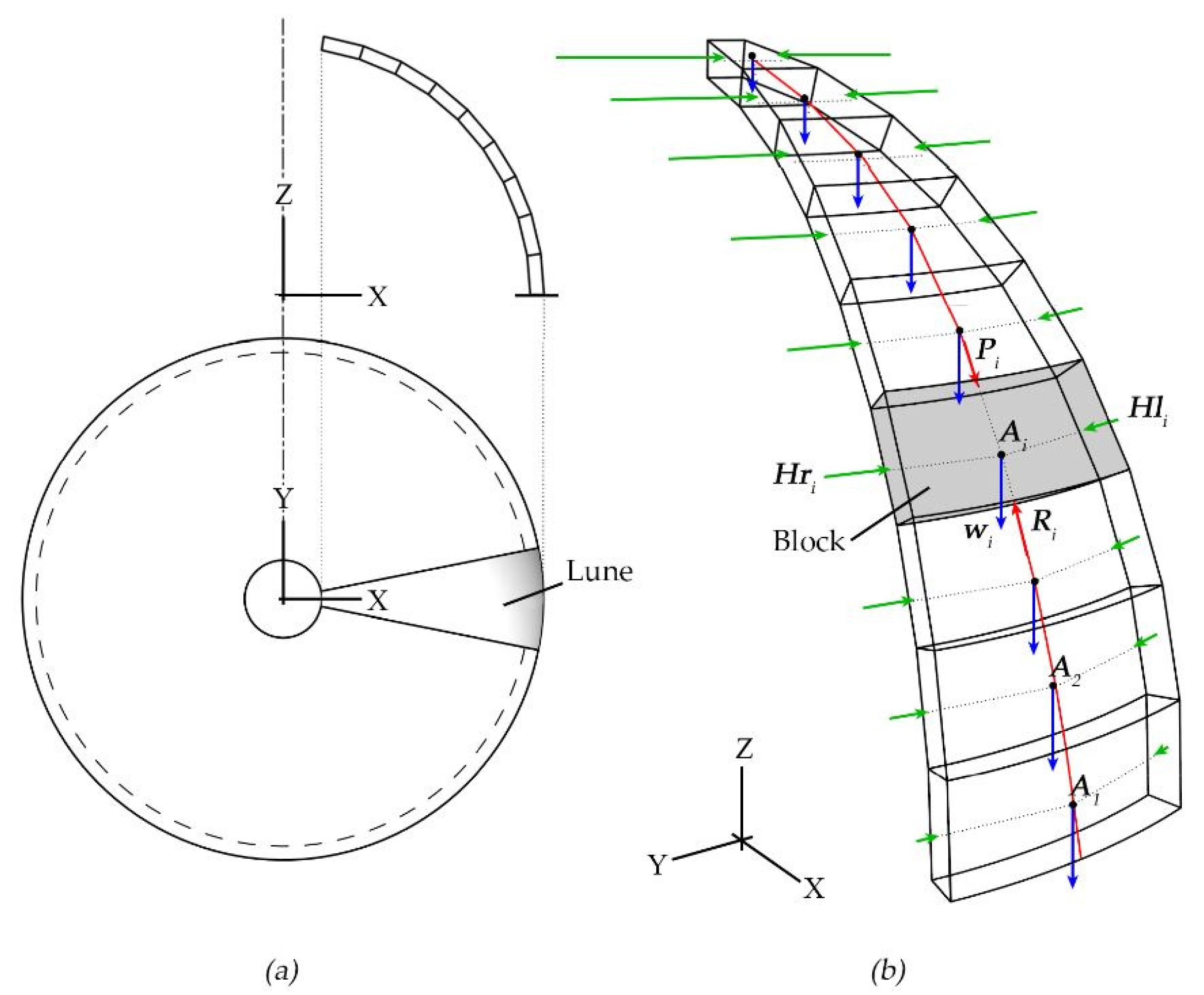
3.3.3. Membrane Equilibrium Analysis
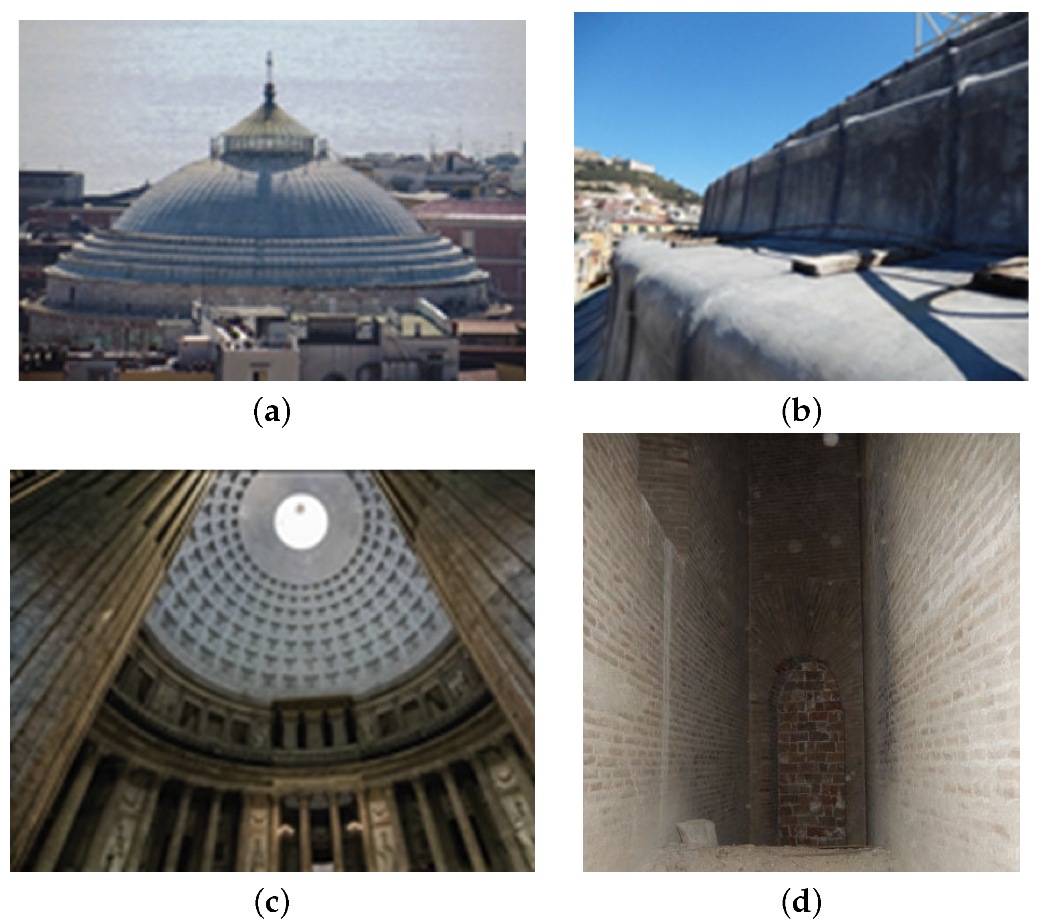
4. The Case Study of San Francesco di Paola
4.1. Previous Calculation on the Case Study
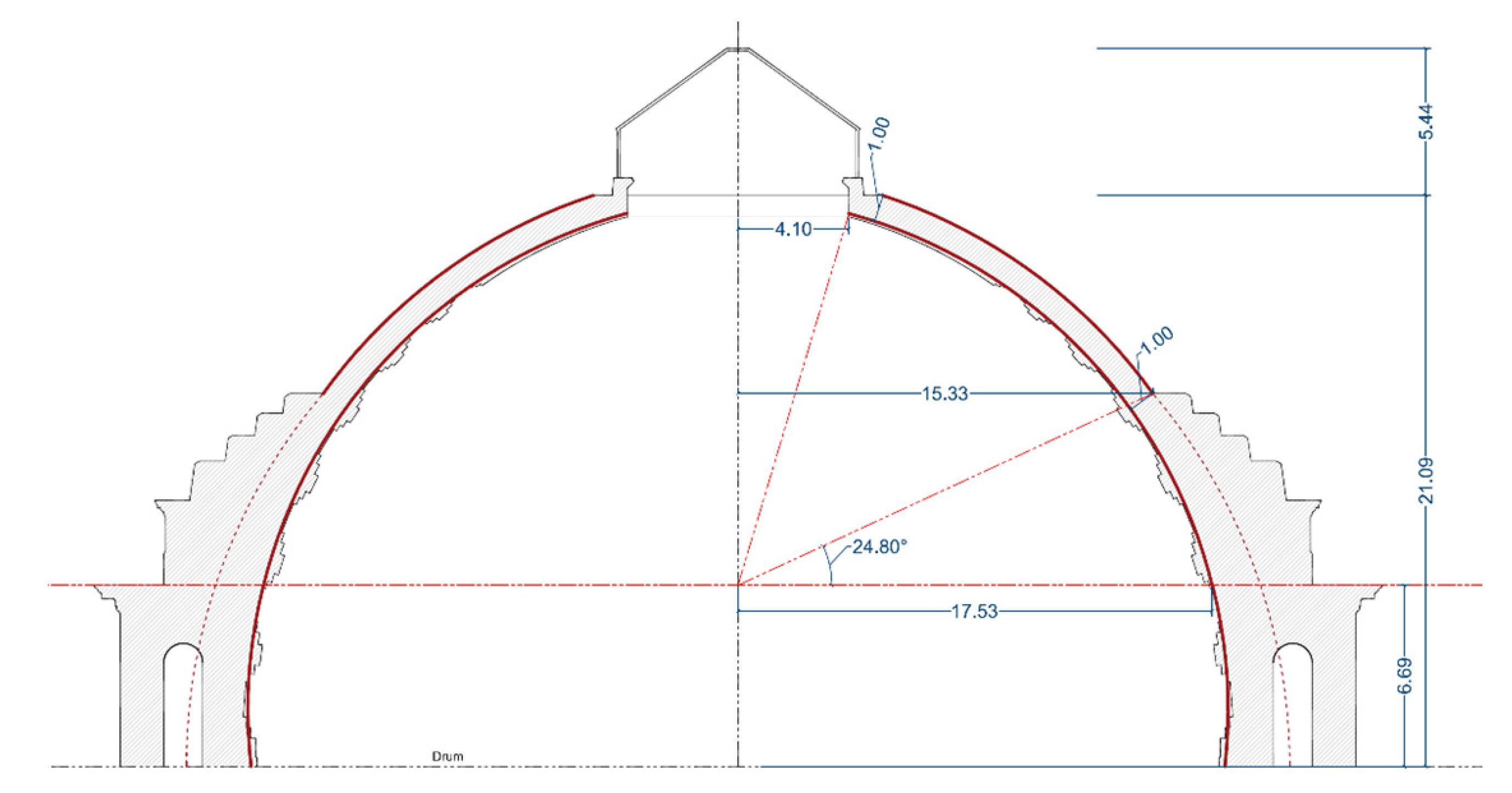
4.2. Geometrical Parameters
4.3. Application
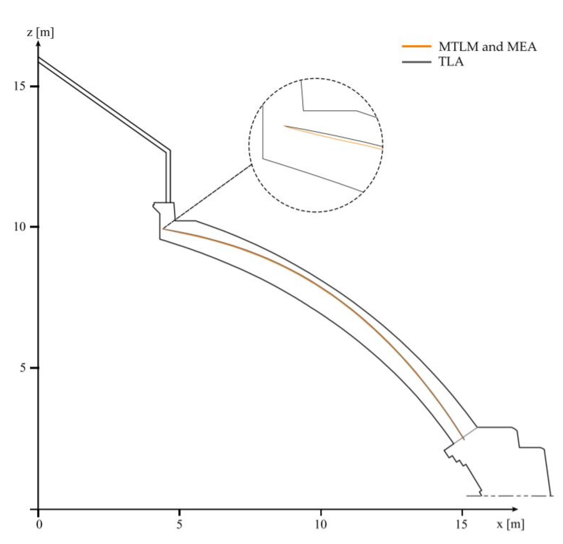
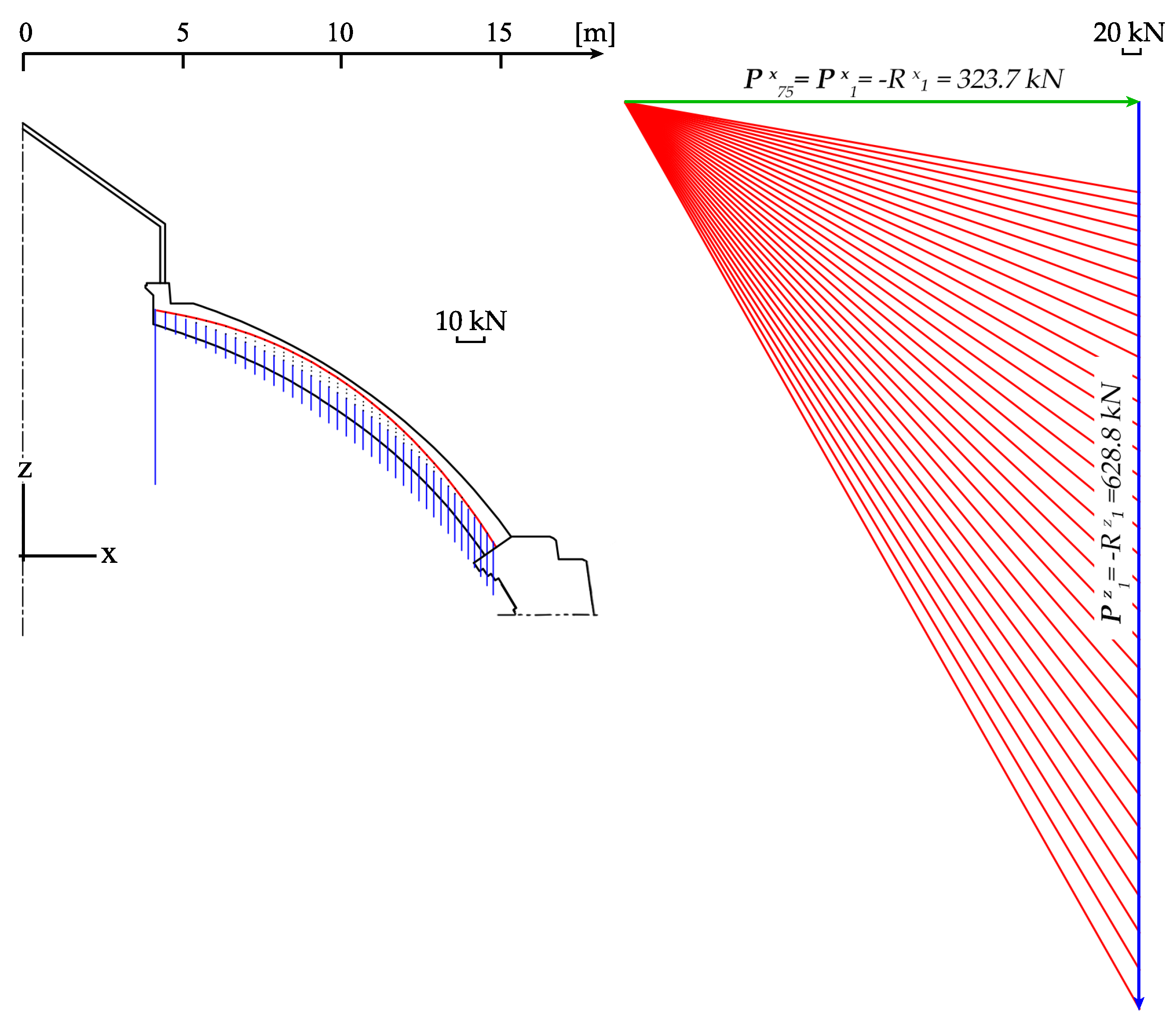
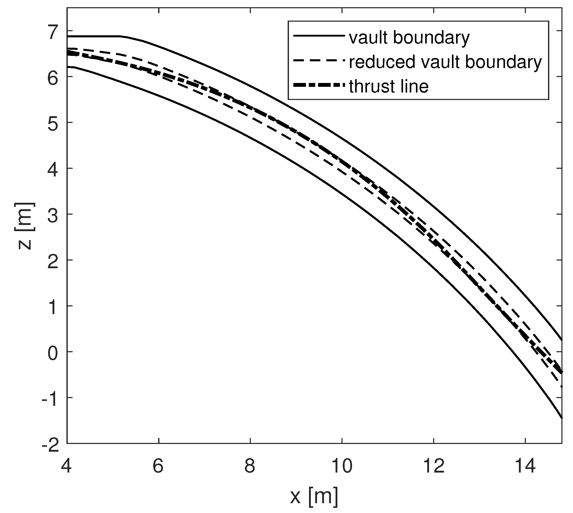
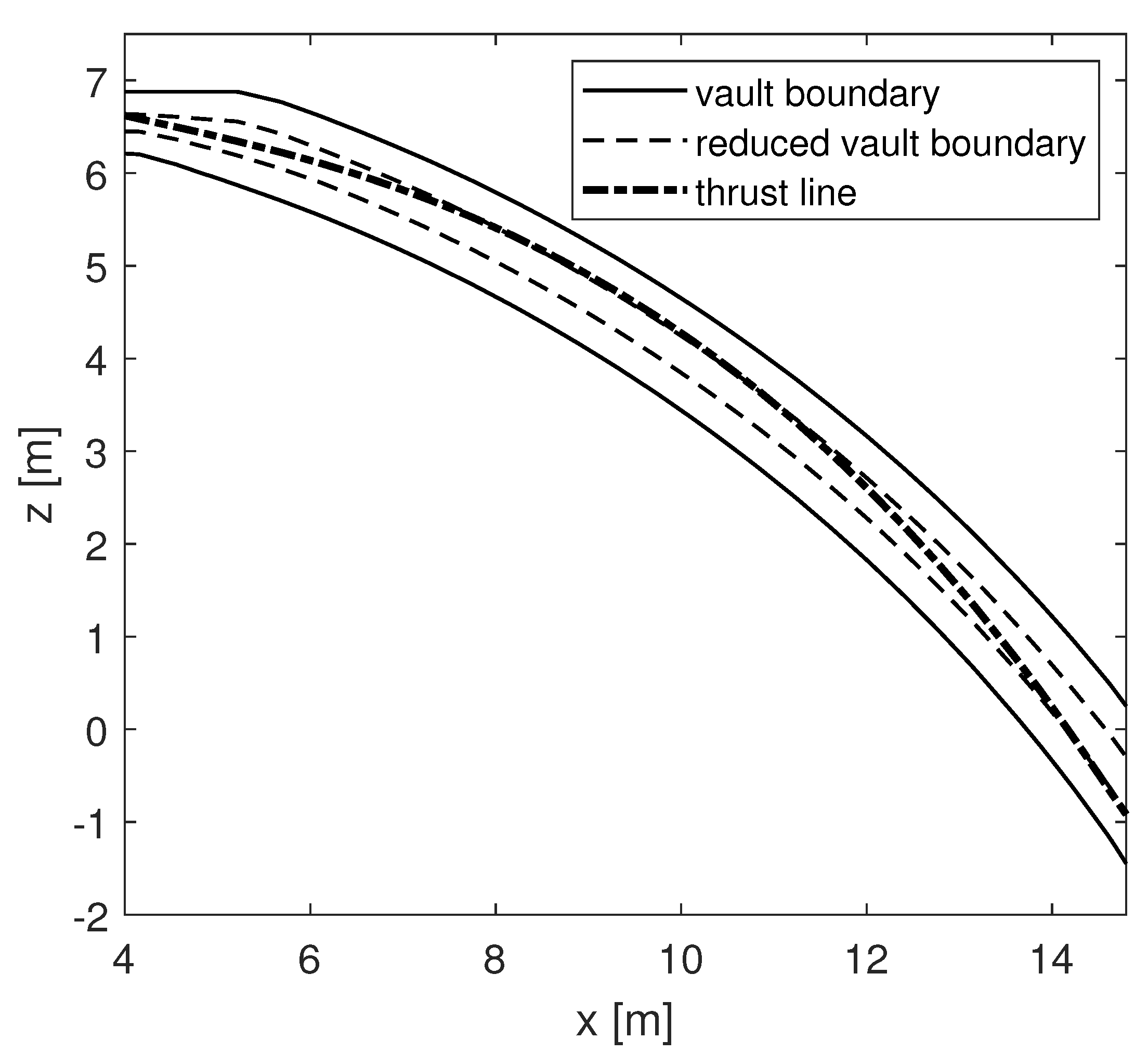
4.3.1. MTLM and TLA
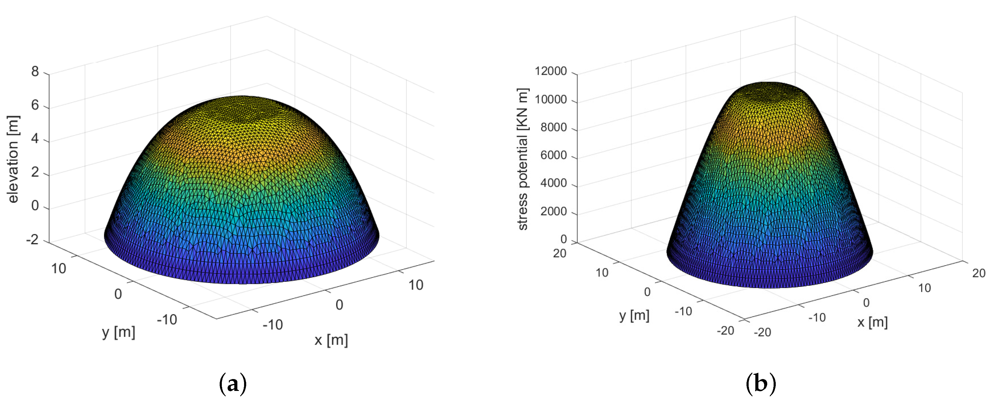
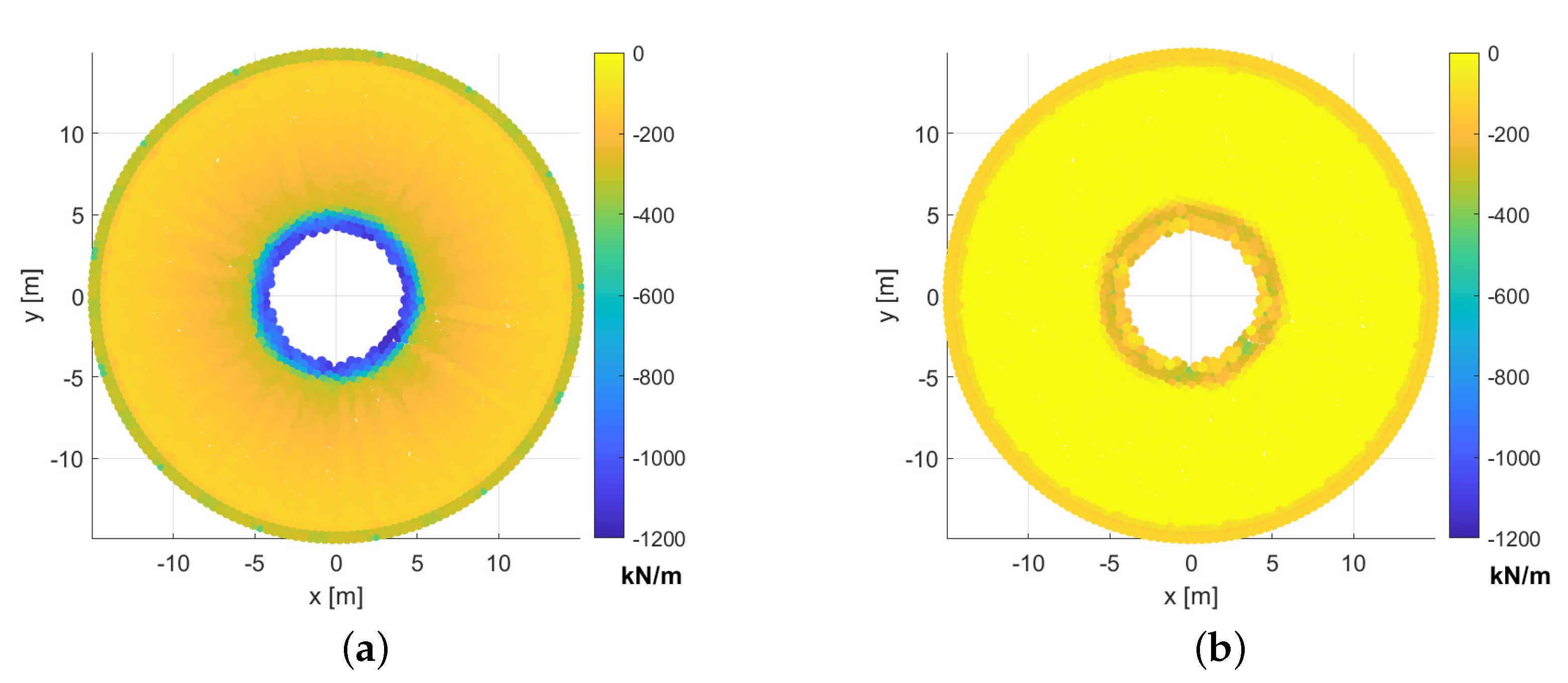
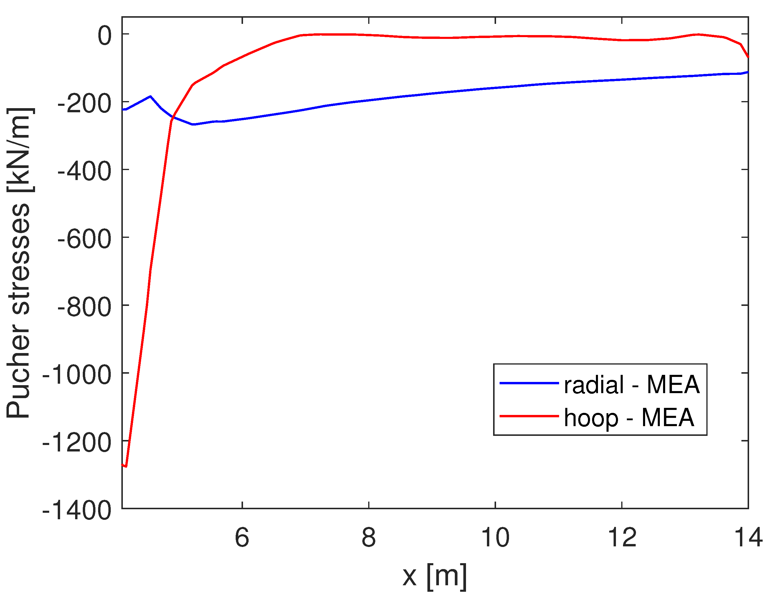
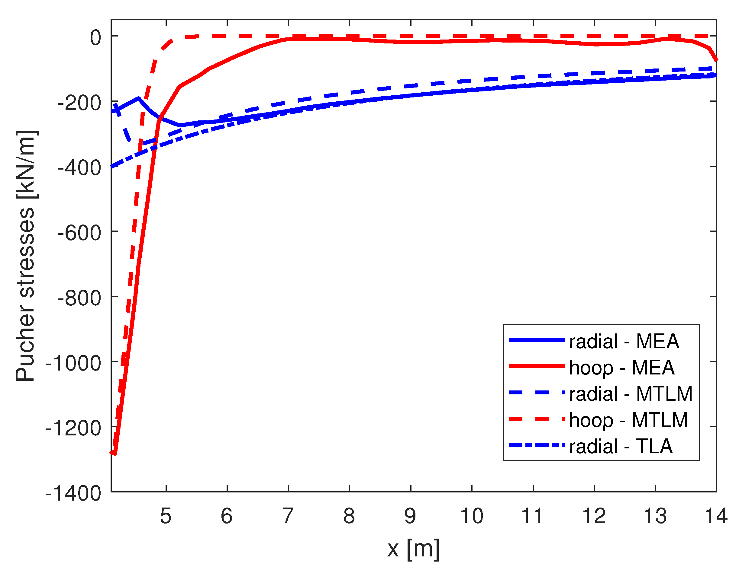
4.3.2. MEA
4.4. Geometrical Safety Factors
5. Results and Discussion
6. Conclusions
Author Contributions
Funding
Conflicts of Interest
References
- Heyman, J. The stone skeleton. Int. J. Solids Struct. 1966, 2, 249–279. [Google Scholar] [CrossRef]
- Cennamo, C.; Cusano, C.; Angelillo, M. The neoclassical dome of San Francesco di Paola in Naples. A study on form and stability. In Proceedings of the XXIII Conference of the Italian Association of Theoretical and Applied Mechanics, Salerno, Italy, 4–7 September 2017; Volume 4, pp. 1439–1448. [Google Scholar]
- Cennamo, C.; Cusano, C.; Angelillo, M. A limit analysis approach for masonry domes: The basilica of San Francesco di Paola in Naples. Int. J. Mason. Res. Innov. 2019, 4, 227–242. [Google Scholar] [CrossRef]
- Cennamo, C.; Cusano, C.; Angelillo, M. On the statics of large domes: A static and kinematic approach for San Francesco di Paola in Naples. In Proceedings of the British Masonry Society, Milan, Italy, 9–11 July 2018; pp. 504–517. [Google Scholar]
- Cennamo, C.; Cusano, C.; Fortunato, A.; Angelillo, M. A study on form and seismic vulnerability of the dome of San Francesco di Paola in Naples. Ing. Sismica 2018, 35, 88–108. [Google Scholar]
- Cusano, C.; Cennamo, C.; Angelillo, M. Stability analysis and seismic vulnerability of large masonry domes. Mason. Int. 2019, 32, 55–62. [Google Scholar]
- Cusano, C.; Cennamo, C.; Angelillo, M. Seismic vulnerability of domes: A case study. J. Mech. Mater. Struct. 2019, 13, 679–689. [Google Scholar] [CrossRef]
- Block, P.; Lachauer, L. Three-dimensional (3D) equilibrium analysis of gothic masonry vaults. Int. J. Archit. Herit. 2014, 8, 312–335. [Google Scholar] [CrossRef]
- Eddy, H.T. Researches in Graphical Statics; D.Van Nostrand: New York, NY, USA, 1878. [Google Scholar]
- Angelillo, M.; Fortunato, A. Equilibrium of masonry vaults. In Novel Approaches in Civil Engineering; Springer: Berlin/Heidelberg, Germany, 2004; pp. 105–111. [Google Scholar]
- Cusano, C.; Angjeliu, G.; Montanino, A.; Zuccaro, G.; Cennamo, C. Considerations about the static response of masonry domes: A comparison between limit analysis and finite element method. Int. J. Mason. Res. Innov. 2021, in press. [Google Scholar]
- Shin, H.V.; Porst, C.F.; Vouga, E.; Ochsendorf, J.; Durand, F. Reconciling elastic and equilibrium methods for static analysis. ACM Trans. Graph. TOG 2016, 35, 1–16. [Google Scholar] [CrossRef]
- Guerra, G. Statica e Tecnica Costruttiva delle Cupole Antiche e Moderne; Istituto di Architettura Tecnica: Napoli, Italy, 1958. [Google Scholar]
- Paris, V.; Pizzigoni, A.; Adriaenssens, S. Statics of self-balancing masonry domes constructed with a cross-herringbone spiraling pattern. Eng. Struct. 2020, 215, 110440. [Google Scholar] [CrossRef]
- Dunn, W. The principles of dome construction: I and II. J. R. Inst. Br. Archit. 1908, 23, 401–412. [Google Scholar]
- Cowan, H.J. Domes—Ancient and Modern. Archit. Sci. Rev. 1977, 20, 38–43. [Google Scholar] [CrossRef]
- Schwedler, J.W. Die konstruktion der kuppeldächer. Z. Bauwes. 1866, 16, 7–34. [Google Scholar]
- Huerta Fernández, S. Arcos, Bóvedas y Cúpulas. Geometría y Equilibrio en el Cálculo Tradicional de Estructuras de FábricaArcos, Bóvedas y Cúpulas: Geometría y Equilibrio en el Cálculo Tradicional de Estructuras de Fábrica; Instituto Juan de Herrera: Madrid, Spain, 2004. [Google Scholar]
- Poleni, G. Memorie Istoriche Della Gran Cvpola Del Tempio Vaticano, E De’Danni Di Essa, E De’Ristoramenti Loro, Divise In Libri Cinqve; Padua Nella Stamperia del Seminario: Padua, Italy, 1748. [Google Scholar]
- Como, M. Statica delle Costruzioni Storiche in Muratura: Archi, Volte, Cupole, Architetture Monumentali, Edifici Sotto Carichi Verticali e Sotto Sisma; Aracne Edizioni: Rome, Italy, 2015. [Google Scholar]
- Rankine, W.J.M. Manual of Applied Mechanics; Griffin: London, UK, 1876. [Google Scholar]
- Wolfe, W.S. Graphical Analysis: A Text Book on Graphic Statics; McGraw-Hill Book Company, Incorporated: New York, NY, USA, 1921. [Google Scholar]
- Lau, W.W. Equilibrium Analysis of Masonry Domes. Ph.D. Thesis, Massachusetts Institute of Technology, Cambridge, MA, USA, 2006. [Google Scholar]
- Ochsendorf, J.A. Collapse of Masonry Structures. Ph.D. Thesis, University of Cambridge, Cambridge, UK, 2002. [Google Scholar]
- Block, P.P.C.V. Thrust Network Analysis: Exploring Three-Dimensional Equilibrium. Ph.D. Thesis, Massachusetts Institute of Technology, Cambridge, MA, USA, 2009. [Google Scholar]
- Huerta Fernández, S. Mechanics of masonry vaults: The equilibrium approach. In Historical Constructions: Possibilities of Numerical and Experimental Techniques; Universidade do Minho: Guimaraes, Portugal, 2001. [Google Scholar]
- Ochsendorf, J.A.; Block, P. Designing unreinforced masonry. In Form and Forces: Designing Efficient, Expressive Structures; Wiley: Hoboken, NJ, USA, 2010; pp. 215–245. [Google Scholar]
- Como, M. Statics of Historic Masonry Constructions; Springer: Berlin/Heidelberg, Germany, 2013; Volume 1. [Google Scholar]
- Manzanares, G.L.; Fernández, S.H. Estabilidad y Construcción de Cúpulas de Fábrica: El Nacimiento de la Teoría y su Relación con la Práctica. Ph.D. Thesis, Universidad Politécnica de Madrid, Madrid, Spain, 1999. [Google Scholar]
- Huerta Fernández, S. Mecánica de las Bóvedas de la Catedral de Gerona; Universidad Politecnica de Madrid: Madrid, Spain, 2004. [Google Scholar]
- Huerta, S.; Fuentes, P. The Cathedral of Girona and the Language of Equilibrium. In Konstruktionssprachen; Birkhäuser: Basel, Switzerland, 2020; pp. 101–130. [Google Scholar]
- Huerta Fernández, S. Informe Sobre la Estabilidad de la Bóveda de la Antigua Cocina del Castillo de Bellver (Palma de Mallorca); E.T.S. Arquitectura (UPM): Madrid, Spain, 2008. [Google Scholar]
- Cipriani, B.; Lau, W.W. Construction Techniques in Medieval Cairo: The Domes of Mamluk Mausolea (1250 AD-1517A. D.). In Proceedings of the Second International Congress on Construction History, Cambridge, UK, 29 March–2 April 2006; pp. 695–716. [Google Scholar]
- Gesualdo, A.; Brandonisio, G.; De Luca, A.; Iannuzzo, A.; Montanino, A.; Olivieri, C. Limit analysis of cloister vaults: The case study of Palazzo Caracciolo di Avellino. J. Mech. Mater. Struct. 2019, 14, 739–750. [Google Scholar] [CrossRef]
- Contestabile, M.; Babilio, E.; Fortunato, A.; Guerriero, L.; Lippiello, M.; Pasquino, M.; Angelillo, M. Static analysis of cross vaults: The case of the Cathedral of Casertavecchia. Open Constr. Build. Technol. J. 2016, 10, 329–345. [Google Scholar] [CrossRef]
- Angelillo, M. Static analysis of a Guastavino helical stair as a layered masonry shell. Compos. Struct. 2015, 119, 298–304. [Google Scholar] [CrossRef]
- Zessin, J.; Lau, W.; Ochsendorf, J. Equilibrium of cracked masonry domes. Proc. Inst. Civ. Eng. Eng. Comput. Mech. 2010, 163, 135–145. [Google Scholar] [CrossRef]
- Davidson, S. Grasshopper Algorithmic Modeling for Rhino. Addons for Grasshopper. Available online: https://www.grasshopper3d.com/ (accessed on 17 March 2021).
- McNeel. Rhino 6 per Windows. Available online: https://www.rhino3d.com/it/ (accessed on 17 March 2021).
- Angelillo, M.; Babilio, E.; Fortunato, A. Singular stress fields for masonry-like vaults. Contin. Mech. Thermodyn. 2013, 25, 423–441. [Google Scholar] [CrossRef]
- De Chiara, E.; Cennamo, C.; Gesualdo, A.; Montanino, A.; Olivieri, C.; Fortunato, A. Automatic generation of statically admissible stress fields in masonry vaults. J. Mech. Mater. Struct. 2019, 14, 719–737. [Google Scholar] [CrossRef]
- Fortunato, A.; Babilio, E.; Lippiello, M.; Gesualdo, A.; Angelillo, M. Limit analysis for unilateral masonry-like structures. Open Constr. Build. Technol. J. 2016, 10, 346–362. [Google Scholar] [CrossRef]
- Angelillo, M.; Montanino, A.; Pandolfi, A. On the Connection Between Geometry and Statically Determined Membrane Stresses in the Human Cornea. J. Biomech. Eng. 2020, 142, 051006. [Google Scholar] [CrossRef]
- Olivieri, C.; Angelillo, M.; Gesualdo, A.; Iannuzzo, A.; Fortunato, A. Parametric design of purely compressed shells. Mech. Mater. 2021, 155, 103782. [Google Scholar] [CrossRef]
- Fraternali, F.; Angelillo, M.; Fortunato, A. A lumped stress method for plane elastic problems and the discrete-continuum approximation. Int. J. Solids Struct. 2002, 39, 6211–6240. [Google Scholar] [CrossRef]
- Iannuzzo, A.; Olivieri, C.; Fortunato, A. Displacement capacity of masonry structures under horizontal actions via PRD method. J. Mech. Mater. Struct. 2019, 14, 703–718. [Google Scholar] [CrossRef]
- Iannuzzo, A.; Van Mele, T.; Block, P. Piecewise rigid displacement (PRD) method: A limit analysis-based approach to detect mechanisms and internal forces through two dual energy criteria. Mech. Res. Commun. 2020, 107, 103557. [Google Scholar] [CrossRef]
- Iannuzzo, A.; Dell’Endice, A.; Van Mele, T.; Block, P. Numerical limit analysis-based modelling of masonry structures subjected to large displacements. Comput. Struct. 2021, 242, 106372. [Google Scholar] [CrossRef]
- Heyman, J. The Stone Skeleton: Structural Engineering of Masonry Architecture; Cambridge University Press: Cambridge, UK, 1997. [Google Scholar]


| MTLM | 170.0 | 54.9 | 322.5 | 628.8 | 867.2 | 0.16 |
| TLA | 323.7 | 54.9 | 323.7 | 628.8 | 0 | 0 |
| Radial75 | Radial1 | Hoop75 | Hoop1 | |
|---|---|---|---|---|
| MTLM | 208 | 100 | 1258 | 0 |
| TLA | 401 | 118 | 0 | 0 |
| MEA | 201 | 117 | 1280 | 50 |
Publisher’s Note: MDPI stays neutral with regard to jurisdictional claims in published maps and institutional affiliations. |
© 2021 by the authors. Licensee MDPI, Basel, Switzerland. This article is an open access article distributed under the terms and conditions of the Creative Commons Attribution (CC BY) license (https://creativecommons.org/licenses/by/4.0/).
Share and Cite
Cusano, C.; Montanino, A.; Olivieri, C.; Paris, V.; Cennamo, C. Graphical and Analytical Quantitative Comparison in the Domes Assessment: The Case of San Francesco di Paola. Appl. Sci. 2021, 11, 3622. https://doi.org/10.3390/app11083622
Cusano C, Montanino A, Olivieri C, Paris V, Cennamo C. Graphical and Analytical Quantitative Comparison in the Domes Assessment: The Case of San Francesco di Paola. Applied Sciences. 2021; 11(8):3622. https://doi.org/10.3390/app11083622
Chicago/Turabian StyleCusano, Concetta, Andrea Montanino, Carlo Olivieri, Vittorio Paris, and Claudia Cennamo. 2021. "Graphical and Analytical Quantitative Comparison in the Domes Assessment: The Case of San Francesco di Paola" Applied Sciences 11, no. 8: 3622. https://doi.org/10.3390/app11083622
APA StyleCusano, C., Montanino, A., Olivieri, C., Paris, V., & Cennamo, C. (2021). Graphical and Analytical Quantitative Comparison in the Domes Assessment: The Case of San Francesco di Paola. Applied Sciences, 11(8), 3622. https://doi.org/10.3390/app11083622