
Investigation of Integral and Differential Characteristics of Variatropic Structure Heavy Concretes by Ultrasonic Methods


 ,
, 

Abstract
1. Introduction
- (i)
- The strength of concrete may increase under favorable temperature and humidity conditions due to the continuing hydration of cement;
- (ii)
- Micro-fractures of the structure appear in concrete under the influence of the environment; however, the continuing hydration of the cement compensates for the decrease in strength from these micro-fractures, and the strength of concrete remains constant as a whole;
- (iii)
- There is an intense accumulation of microdestructions in the concrete structure under the influence of the environment; due to unfavorable temperature and humidity conditions, the cement hydration is either completely absent or proceeds extremely slowly, and as a result, a steady decrease in the strength of concrete occurs.
2. Overview of Theoretical and Experimental Methods
3. Application of the Ultrasonic Method for the Control of Concrete Properties
4. Materials and Methods
- (i)
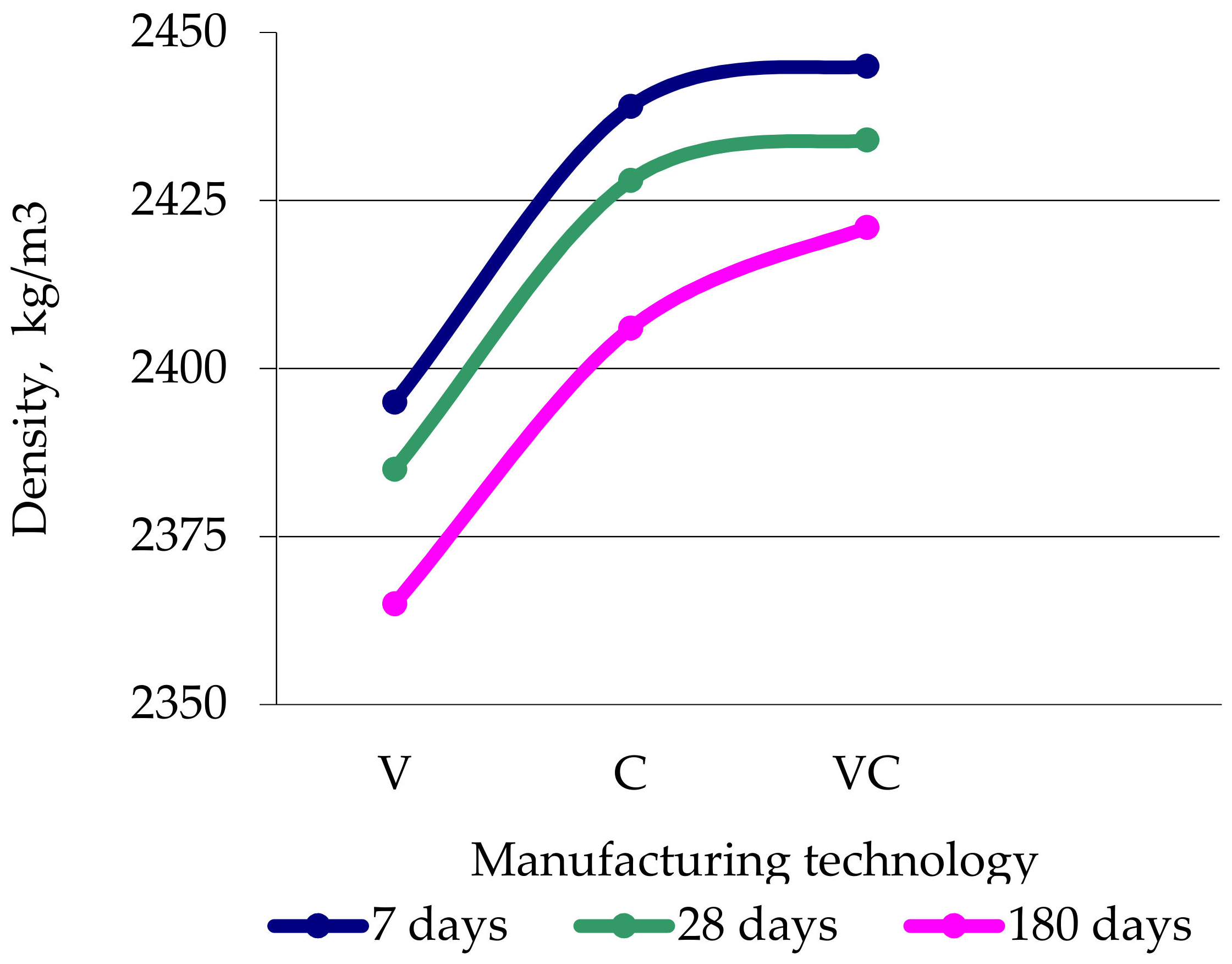
- Density ρ;
- (ii)
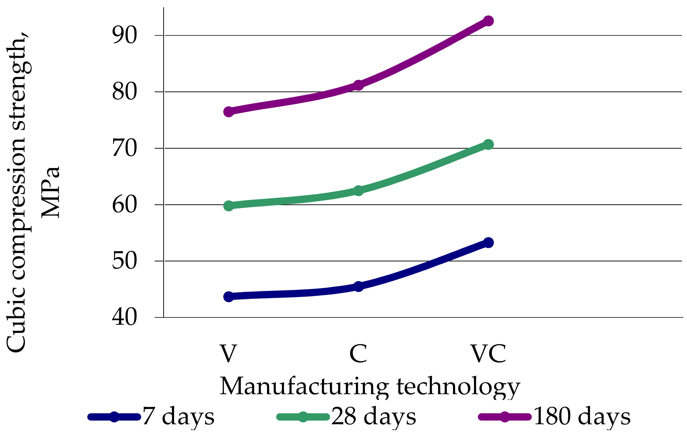
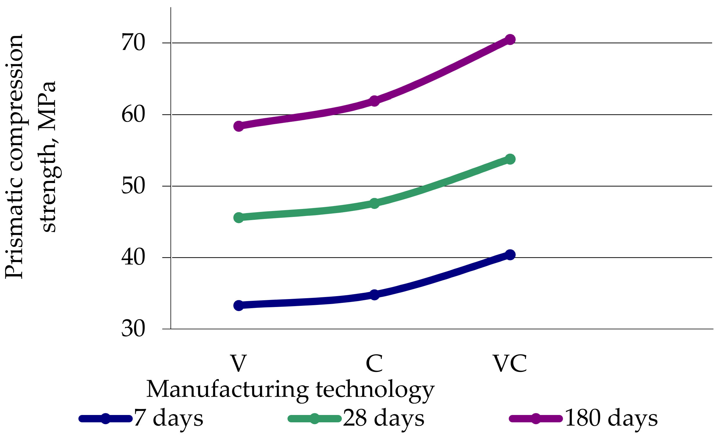
- Axial compression strength (cubic Rb,cub and prismatic Rb);
- (iii)
- Limiting strains during axial compression ;
- (iv)
- Axial tensile Rbt and flexural tensile strength Rbtb,i;
- (v)
- Limiting strains during axial tension ;
- (vi)
- Elastic modulus (in compression Eb and tension Ebt);
- (vii)
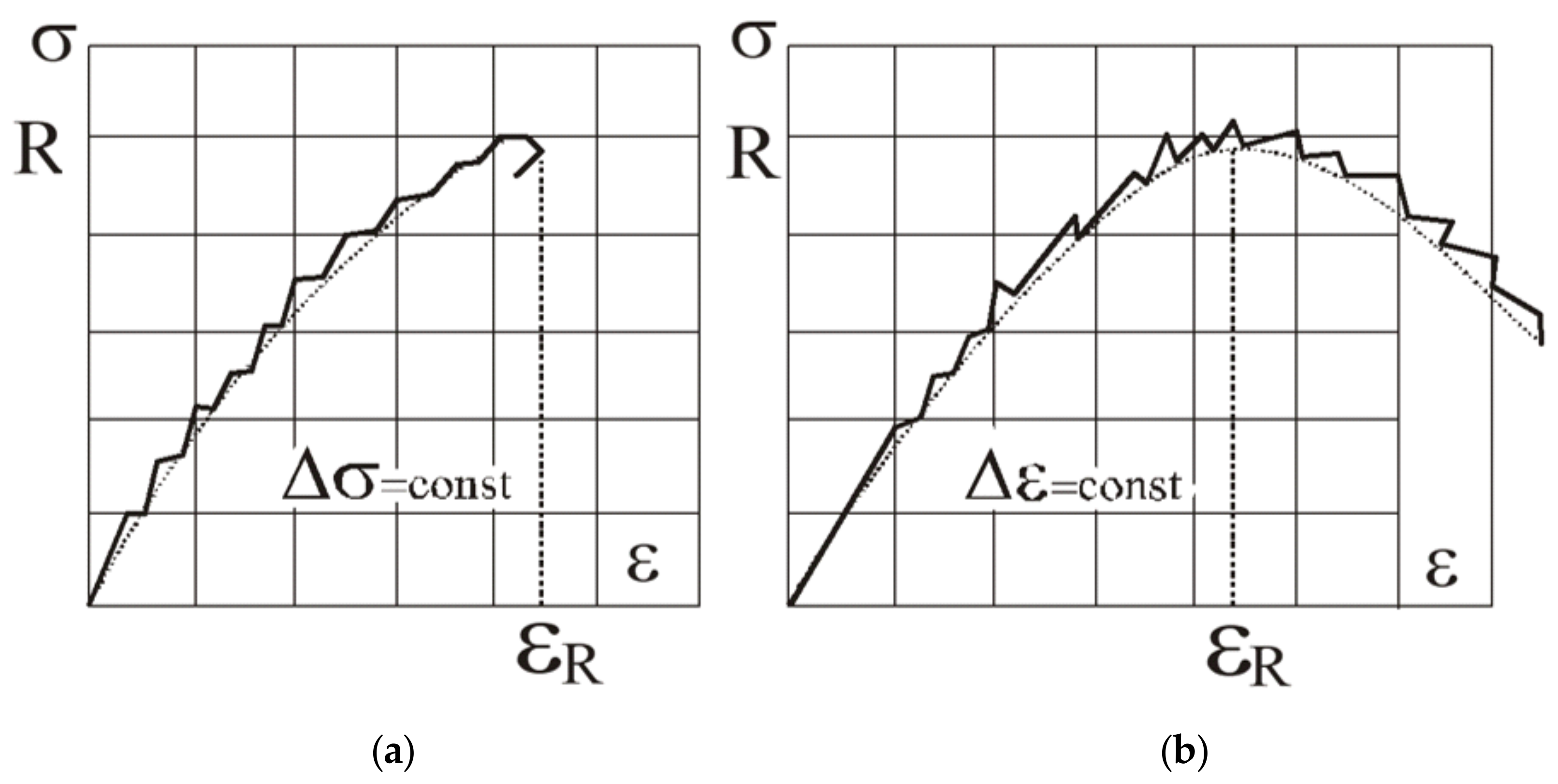
- Diagram “stress –strain ” in compression;
- (viii)
- Diagram “stress –strain ” in tension.
- (i)
- Granite crushed stone of the JSC “Pavlovsk Nerud” (Russia) with a fraction of 5–20 mm;
- (ii)
- Quartz sand of the Grushevskoye deposit (Russia), Mk = 2.0.
- (i)
- The values of Rb,cub in the results of testing cubes on axial compression;
- (ii)
- The values of Rb, εbR, Rbt, εbtR, Εb = Εbt and the deformation diagram “σb–εb” in the results of testing prisms on axial compression;
- (iii)
- The values of Rbt and deformation diagram “σbt–εbt” in the results of testing prisms on axial tension;
- (iv)
- The values of Rbtb in the results of testing prisms on tension in bending.
- (i)
- Manufacturing technology (vibration, centrifugation, vibro-centrifugation);
- (ii)
- Type of stress–strain state (axial compression and axial tension);
- (iii)
- Type of sample (cubes, 50 × 50 × 50 mm3 and 150 × 150 × 150 mm3; prisms 50 × 50 × 200 mm3 and 150 × 150 × 600 mm3);
- (iv)
- Test mode (with constant loading rate and constant deformation rate);
- (v)
- Concrete age (7, 28 and 180 days).
5. Results and Discussion
5.1. Study of the Integral Design Characteristics of Vibrated, Centrifuged and Vibro-Centrifuged Concretes
5.1.1. Research Results of the Integral Characteristics of Concrete
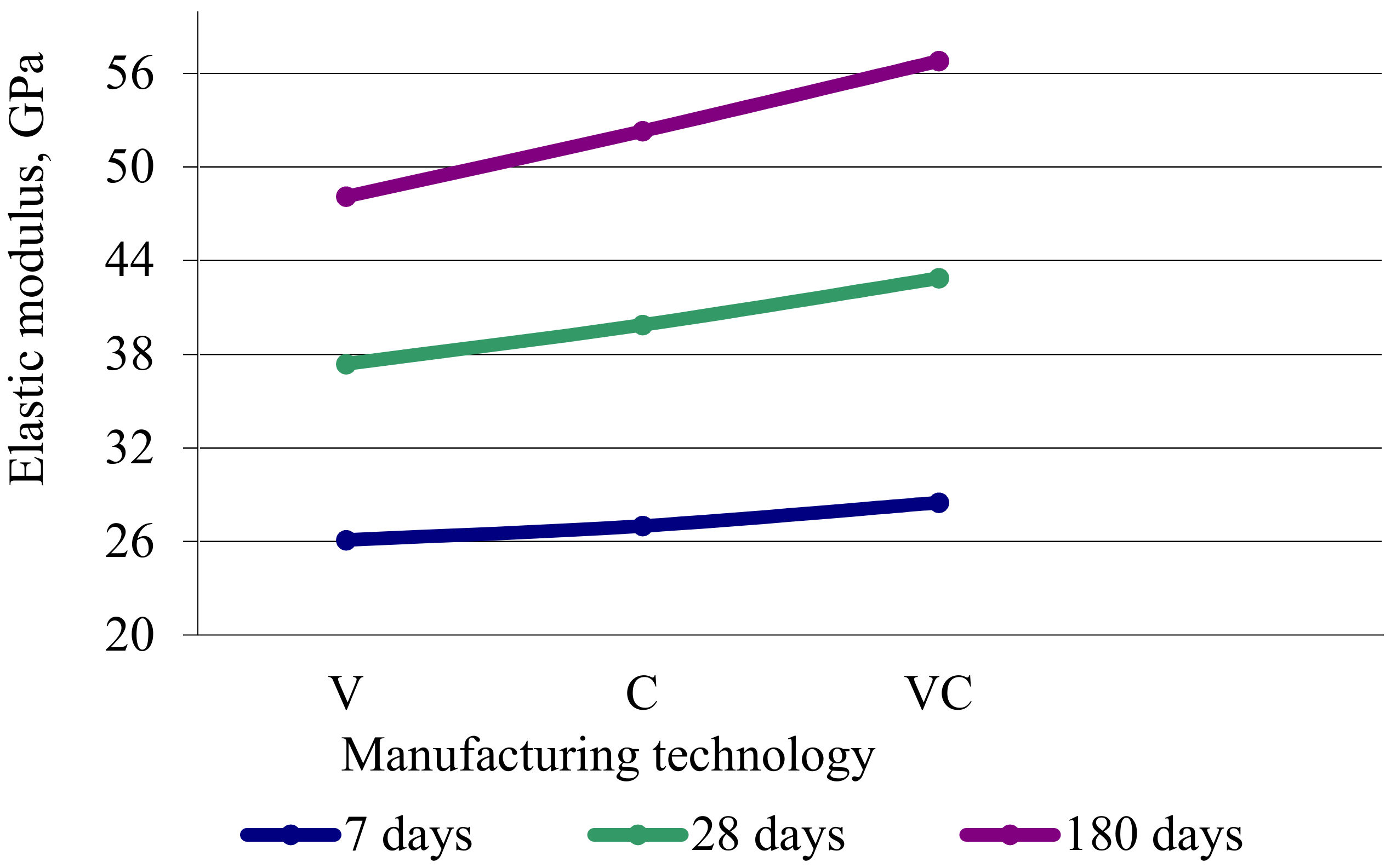
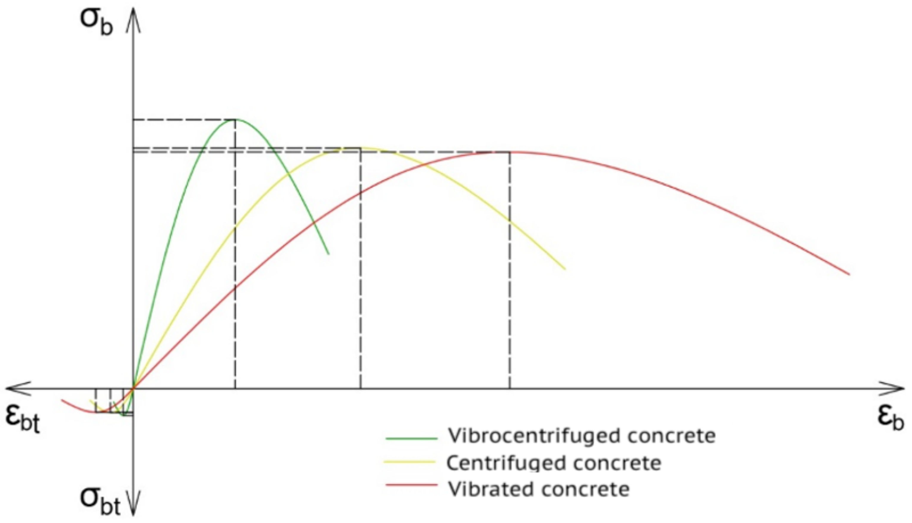
5.1.2. Analysis of Integral Density, Strength, Limiting Deformations, Elasticity Modulus and Deformation Diagrams of Concrete in Compression and Tension
- (i)
- The maximum shifts were up and to the left (strength increases, and limiting strain decrease);
- (ii)
- The angle of rise at the origin of coordinates increases (initial modulus of elasticity increases).
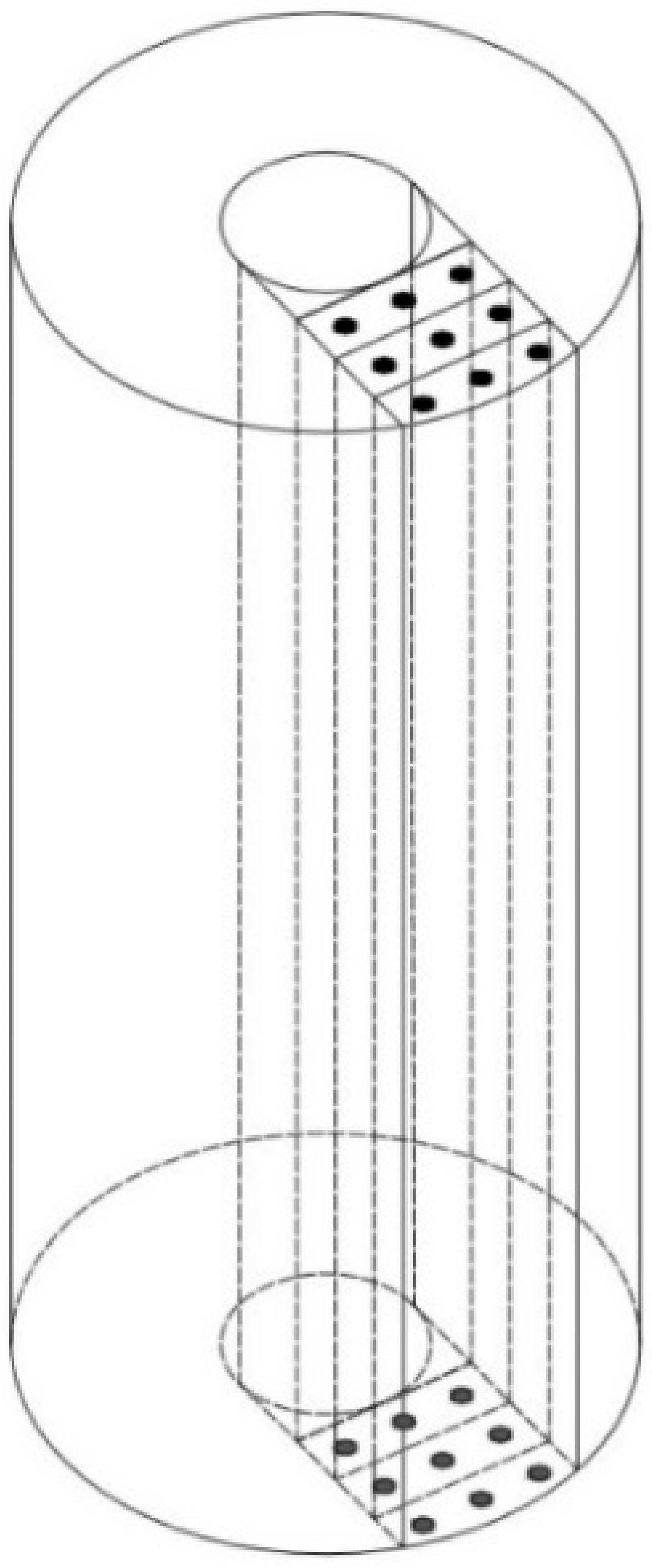
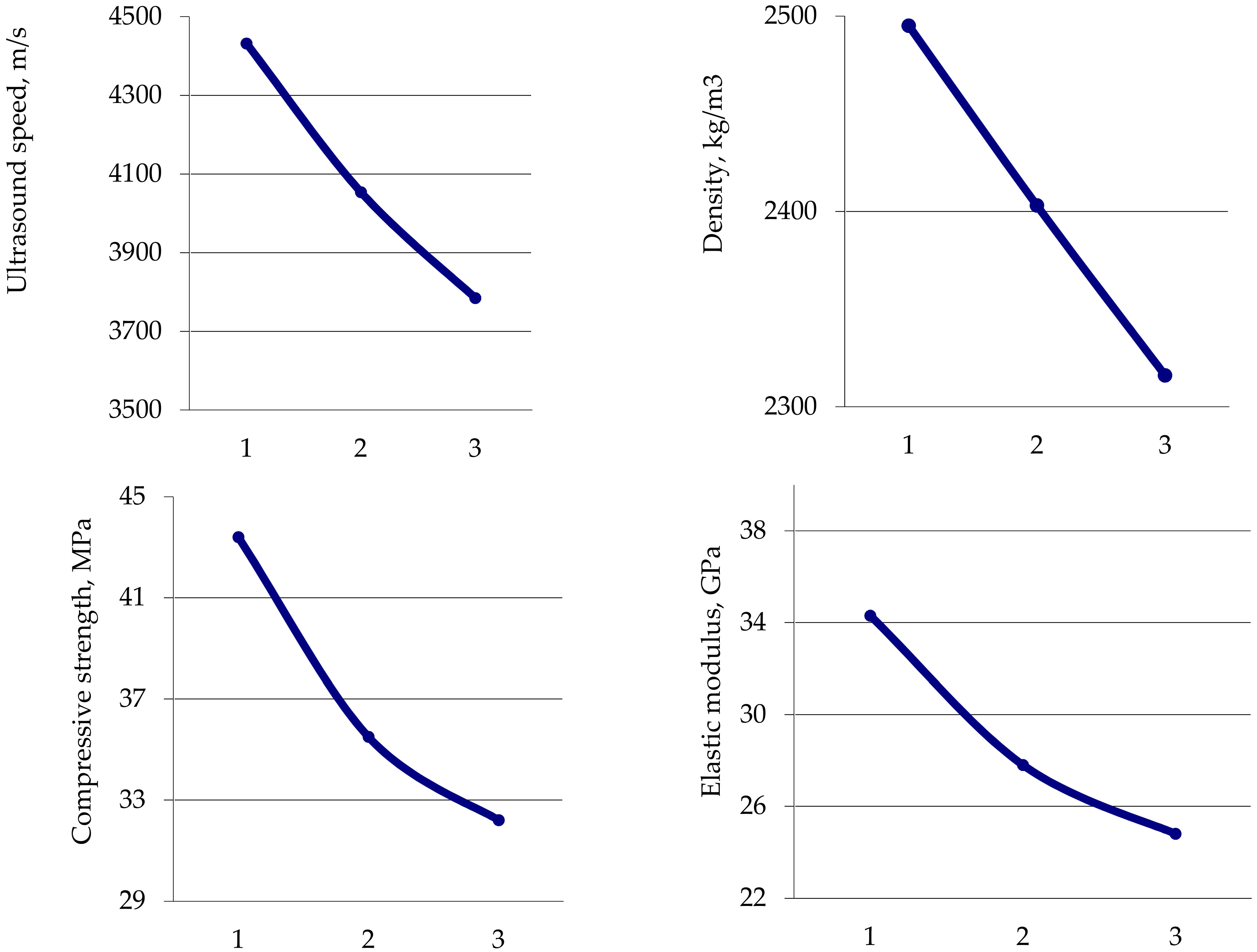
5.2. Study of Differential Design Characteristics of Centrifuged and Vibro-Centrifuged Concretes of Variatropic Sections
5.3. Features of Experimental Research Methods for Differential Characteristics of Concrete by Ultrasonic Method
6. Conclusions
- Experimental methods and instrumental apparatuses were developed for studies of the centrifuged and vibro-centrifuged concrete products with annular cross-sections, which made it possible to assess the picture of the real variatropy of the structure and confirmed that the accepted direction of research was correct.
- An original method of experimental studies of the variatropy of cross-sections of the vibrated, centrifuged and vibro-centrifuged concretes was proposed to determine their integral (common) and differential (differing in layers) strength, strain characteristics and deformation diagrams.
- The experimental studies of the integral characteristics of the vibrated, centrifuged and vibro-centrifuged concretes at the age of 7, 28 and 180 days under compression and tension revealed the following:
- (i)
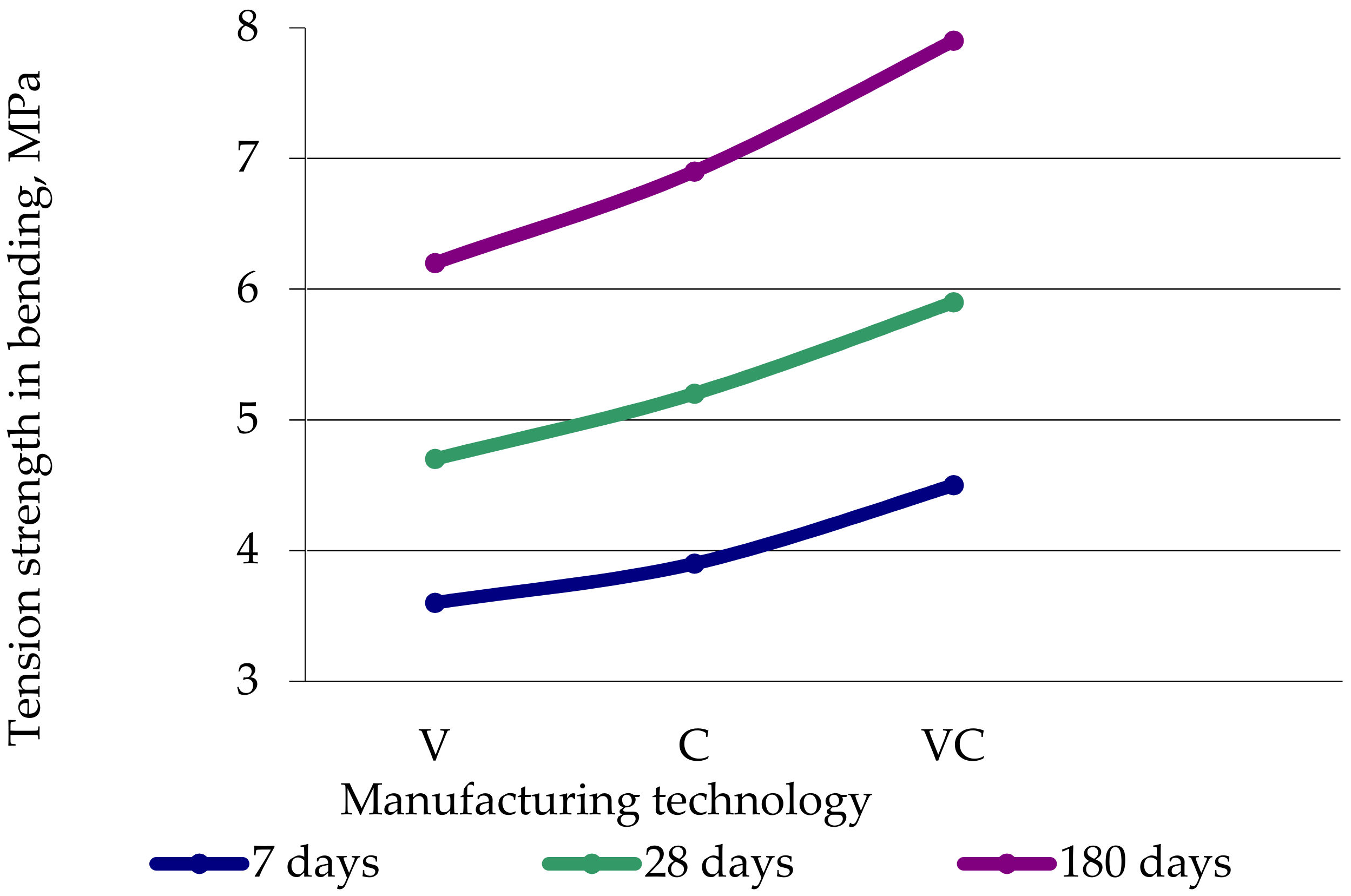
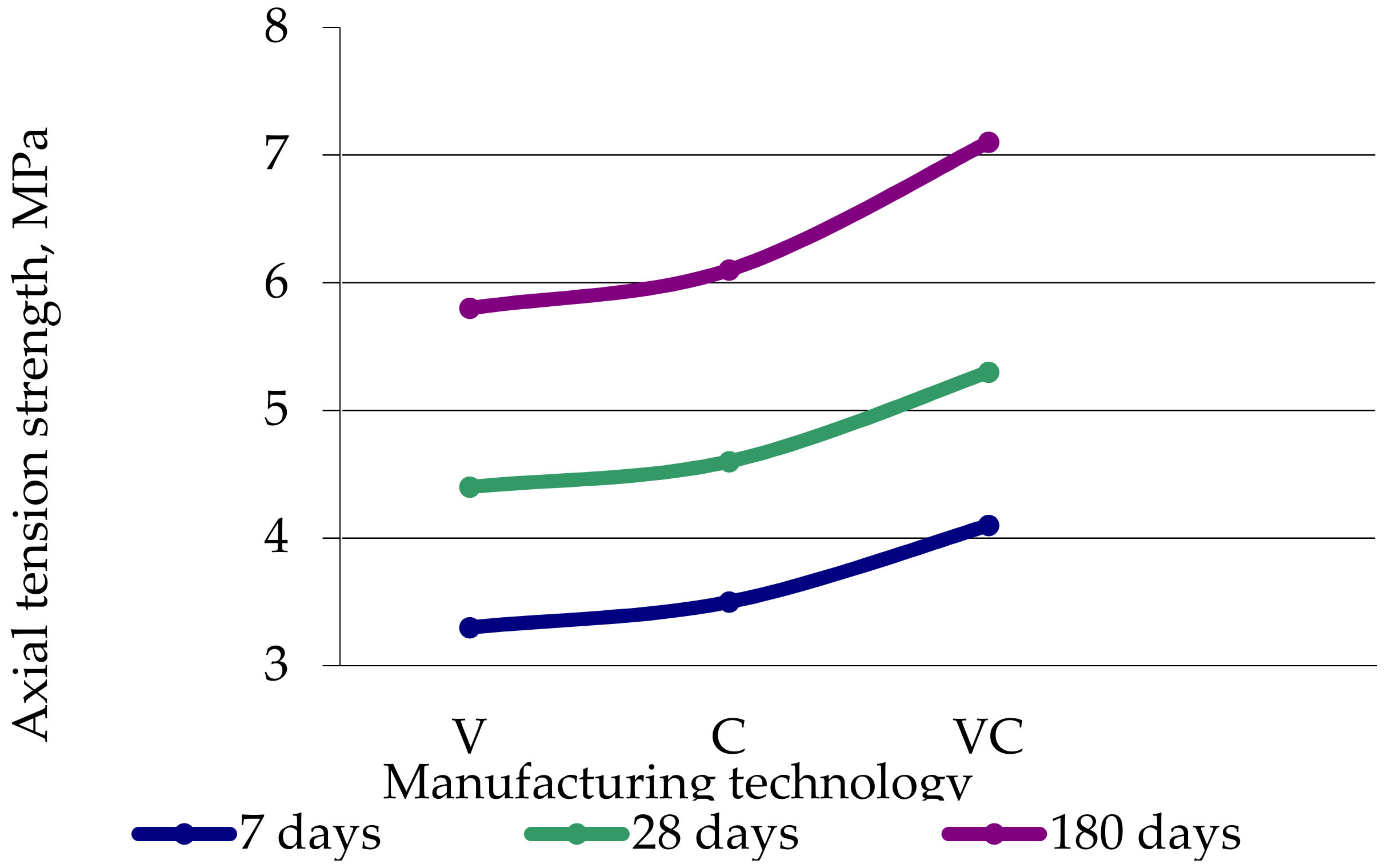
- The characteristics of concretes are higher after vibro-centrifugation compared with centrifugation and vibration, and after centrifugation they are better than after vibration;
- (ii)
- The compression and tension strength increase at all ages up to values of 20–22%;
- (iii)
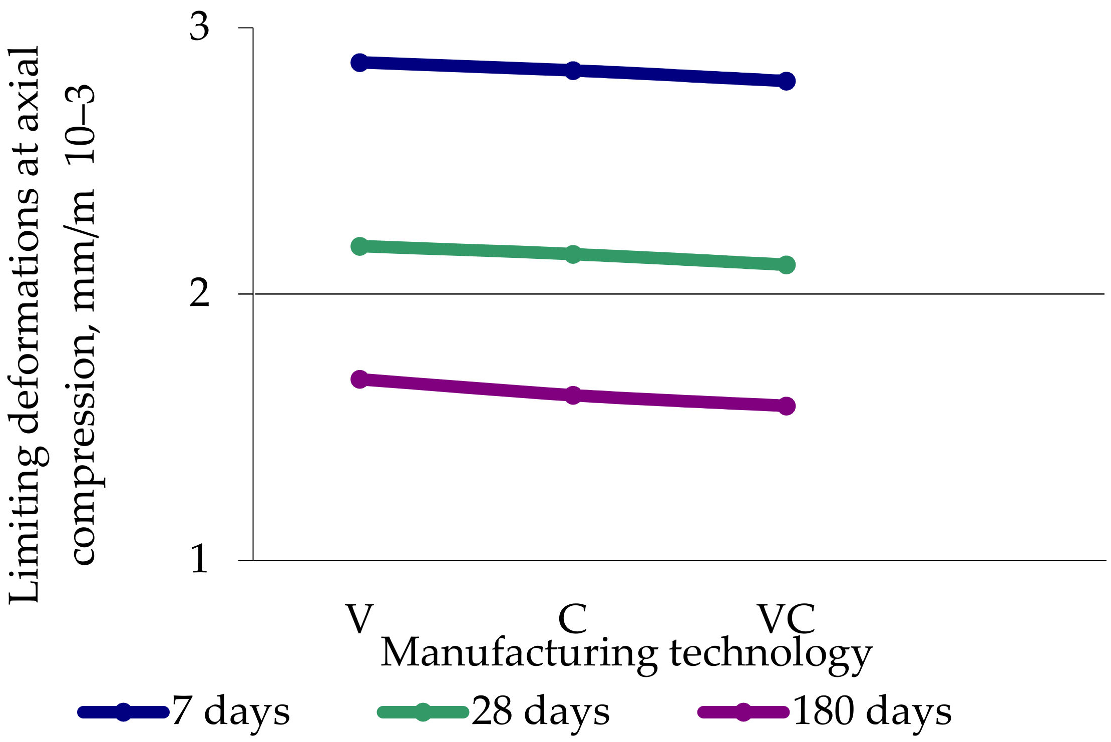
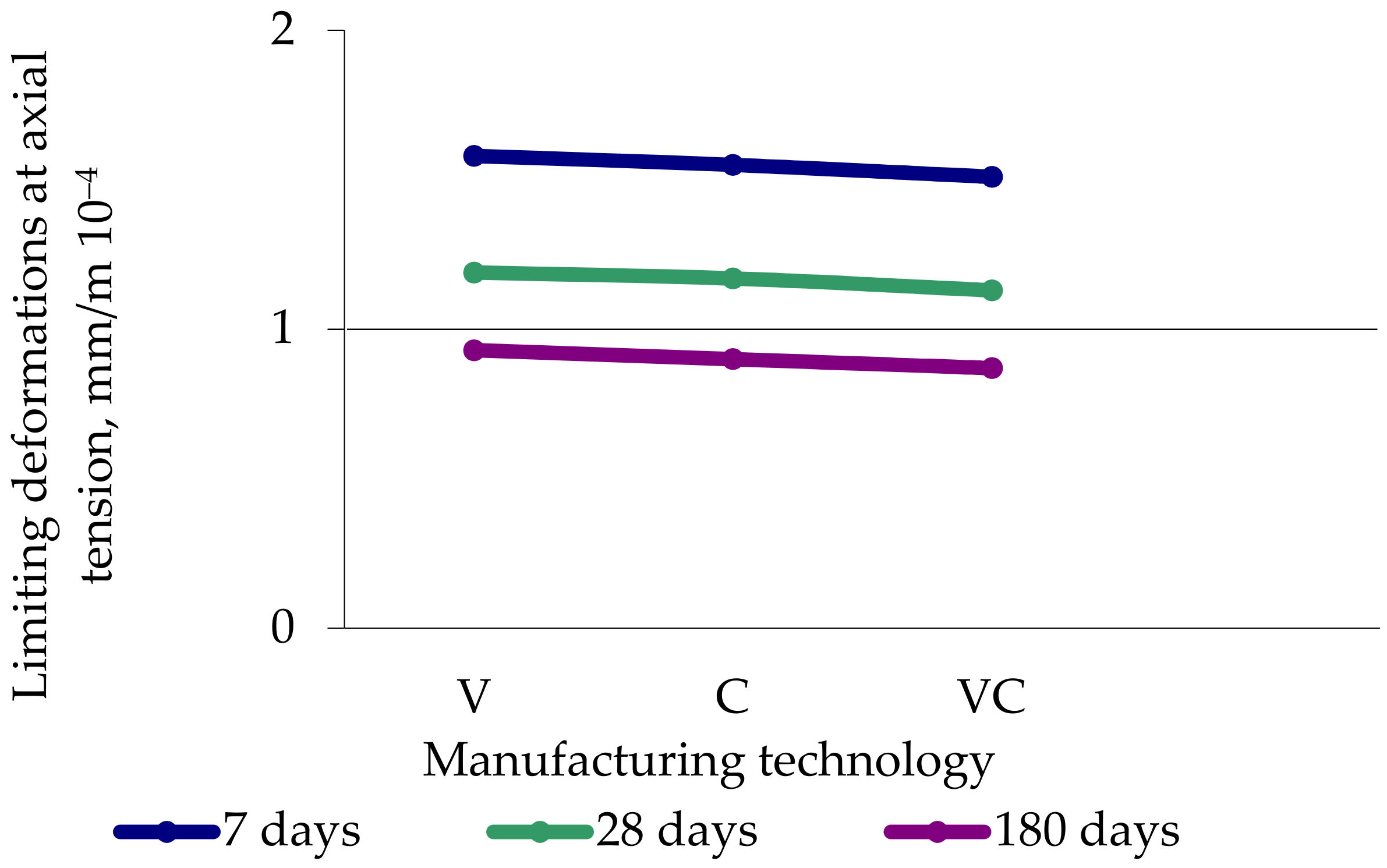
- The limiting strains at axial compression and axial tension decrease up to values of 6–8%;
- (iv)
- The modulus of elasticity at axial compression and axial tension increases up to values of 5–10%.
- It was proved that it becomes possible to obtain concretes with improved structure and higher characteristics at vibro-centrifugation compared with centrifugation and vibration.
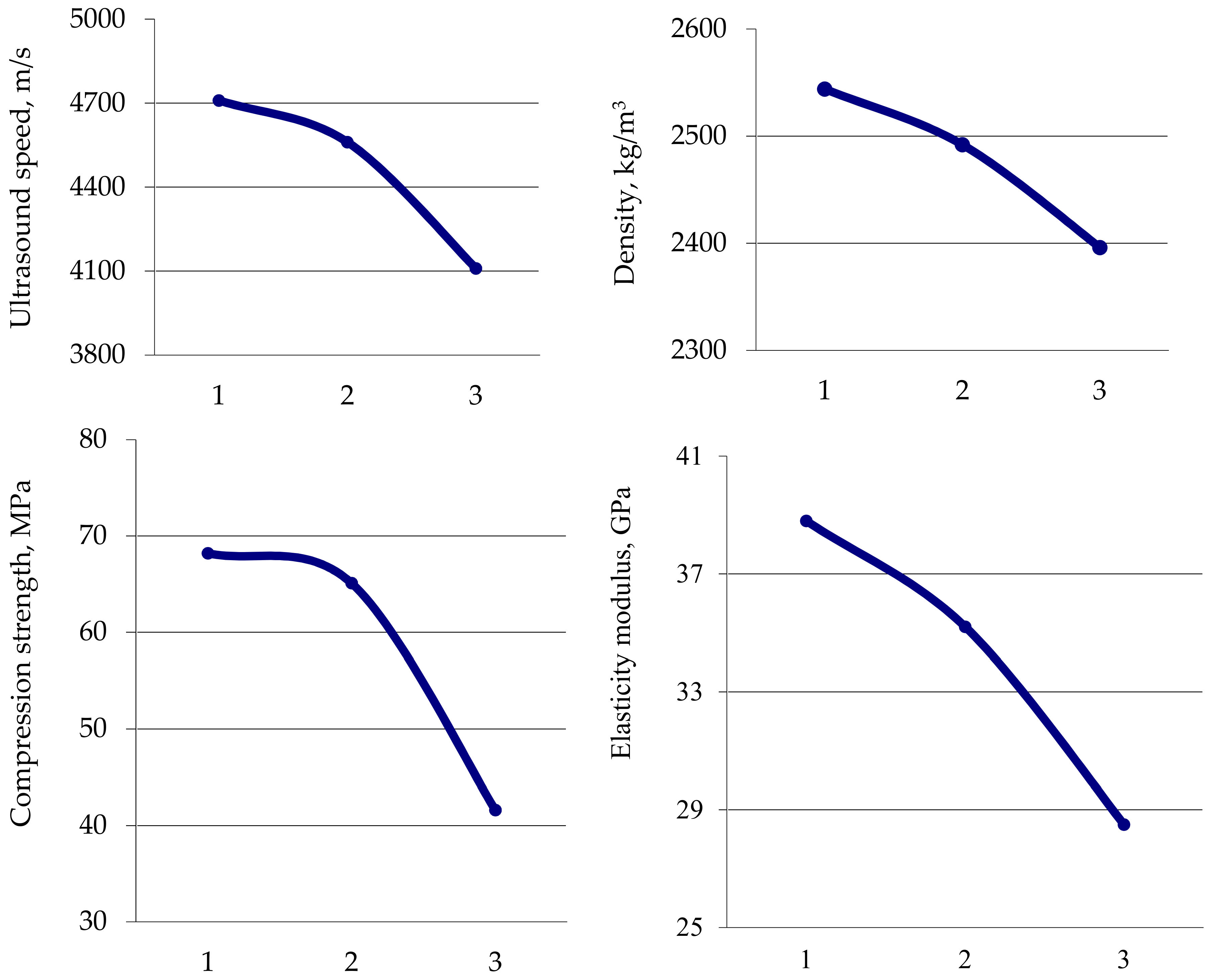
- The experimental studies of the differential characteristics of centrifuged and vibro-centrifuged concretes at compression and tension revealed that the outer layer of concrete has the best characteristics during centrifugation and vibro-centrifugation, and the inner layer has the worst.
- The experimental study confirmed a three-layer model variatropic concrete structure. Differentiation of the characteristics of layers of variatropic concrete was obtained: (i) the concrete of the outer layers has the highest strength, modulus of elasticity and the least deformability; (ii) the concrete of the inner layers has the lowest strength, modulus of elasticity and the highest deformability; (iii) the concrete of the middle layers has average characteristics.
- The diagrams of deformation for the centrifuged and vibro-centrifuged concretes are also differentiated by layers, confirming the variatropy of the structure of such concretes. Of these, the deformation diagrams for the outer concrete layer are the highest in strength, the deformation diagrams for the inner concrete layer are the smallest in strength, and the middle concrete layer demonstrates mean deformation diagrams.
Author Contributions
Funding
Institutional Review Board Statement
Informed Consent Statement
Data Availability Statement
Acknowledgments
Conflicts of Interest
References
- Podolsky, V.I. Reinforced Concrete Supports of the Electric Contact Network. Design, Operation, Diagnostics; All-Russian Scientific-Research Institute of Rail-Road Transport: Moscow, Russia, 2007; p. 152. (In Russian) [Google Scholar]
- Suleimanova, L.A. High-quality energy-saving and competitive building materials, products and structures. Bull. BSTU Named VG Shukhov. 2017, 1, 9–16. (In Russian) [Google Scholar]
- Akhverdov, I.N. Fundamentals of Concrete Physics; Stroyizdat: Moscow, Russia, 1981; p. 464. (In Russian) [Google Scholar]
- Liu, Z.; Chen, X.; Wu, P.; Cheng, X. Investigation on micro-structure of self-compacting concrete modified by recycled grinded tire rubber based on X-ray computed tomography technology. J. Clean. Prod. 2021, 290, 125838. [Google Scholar] [CrossRef]
- Vorobeichikov, S.E.; Fokin, V.A.; Udod, V.A.; Temnik, A.K. A study of two image-recognition algorithms for the classification of flaws in a test object according to its digital image. Russ. J. Nondestruct. Test. 2015, 51, 644–651. [Google Scholar] [CrossRef]
- Dimarogonas, A.D. Vibration of cracked structures: A state of the art review. Eng. Fract. Mech. 1996, 55, 831–857. [Google Scholar] [CrossRef]
- Dado, M.H.; Shpli, O.A. Crack parameter estimation in structures using finite element modeling. Int. J. Solids Struct. 2003, 40, 5389–5406. [Google Scholar] [CrossRef]
- Bamnios, Y.; Douka, E.; Trochidis, A. Crack identification in beam structures using mechanical impedance. J. Sound Vib. 2002, 256, 287–297. [Google Scholar] [CrossRef]
- Cherpakov, A.V.; Shlyakhova, E.A.; Egorochkina, I.O.; Kokareva, Y.A. Identification of Concrete Properties in Beam-Type Structures with Defects Based on Dynamic Methods. Mater. Sci. Forum 2018, 931, 373–378. [Google Scholar] [CrossRef]
- Shevtsov, S.N.; Soloviev, A.N.; Parinov, I.A.; Cherpakov, A.V.; Chebanenko, V.A. Piezoelectric Actuators and Generators for Energy Harvesting—Research and Development; Series: Innovation and Discovery in Russian Science and Engineering; Springer: Cham, Switzerland, 2018; p. 182. ISBN 978-3319756288. [Google Scholar]
- Akopyan, V.A.; Rozhkov, E.V.; Soloviev, A.N.; Shevtsov, S.N.; Cherpakov, A.V. Identification of Damages in Elastic Structures: Approaches, Methods, Analysis; Southern Federal University Press: Rostov-on-Don, Russia, 2015; p. 74. (In Russian) [Google Scholar]
- Wang, Z.; Man, X.T.C.; Finch, R.D.; Jansen, B.H. The Dynamic Behavior and Vibration Monitoring of Reinforced Concrete Beams. J. Test. Eval. 1998, 26, 405–419. [Google Scholar] [CrossRef]
- Orlov, V.; Chichurin, A. On the theory of constructing a numerical-analytical solution of a cantilever beam bend nonlinear differential equation of the first order. J. Phys. Conf. Ser. 2019, 1425, 012129. [Google Scholar] [CrossRef]
- Krasnoshchekov, A.A.; Sobol’, B.V.; Solov’Ev, A.N.; Cherpakov, A.V. Identification of crack-like defects in elastic structural elements on the basis of evolution algorithms. Russ. J. Nondestruct. Test. 2011, 47, 412–419. [Google Scholar] [CrossRef]
- Cherpakov, A.V.; Soloviev, A.N.; Gritsenko, V.V.; Goncharov, O.U. Damages Identification in the Cantilever-based on the Parameters of the Natural Oscillations. Def. Sci. J. 2016, 66, 44–50. [Google Scholar] [CrossRef]
- Popovics, J.S. Comment on ‘‘Determination of elastic constants of a concrete specimen using transient elastic waves’’ [J. Acoust. Soc. Am. 98, 2142–2148 (1995)]. J. Acoust. Soc. Am. 1996, 100, 3451. [Google Scholar] [CrossRef]
- Popovics, J.; Rose, J. An approach for wave velocity measurement in solid cylindrical rods subjected to elastic impact. Int. J. Solids Struct. 1996, 33, 3925–3935. [Google Scholar] [CrossRef]
- Ponzo, F.; Di Cesare, A.; Telesca, A.; Pavese, A.; Furinghetti, M. Advanced Modelling and Risk Analysis of RC Buildings with Sliding Isolation Systems Designed by the Italian Seismic Code. Appl. Sci. 2021, 11, 1938. [Google Scholar] [CrossRef]
- Akopyan, V.A.; Solov’Ev, A.N.; Cherpakov, A.V.; Shevtsov, S.N. On a deformation sign for identifying defects on the basis of the analysis of the forms of the natural vibrations of a cantilever with a notch. Russ. J. Nondestruct. Test. 2013, 49, 579–583. [Google Scholar] [CrossRef]
- Grigoryan, M.N.; Polyakova, T.V.; A Kokareva, Y.; A Parinov, I.; Cherpakov, A.V. The technical state experimental studies of construction with free support in the non-stationary oscillations’ analysis. IOP Conf. Ser. Mater. Sci. Eng. 2021, 1083, 012016. [Google Scholar] [CrossRef]
- Garnier, V.; Corneloup, G.; Sprauel, J.; Perfumo, J. Setting time study of roller compacted concrete by spectral analysis of transmitted ultrasonic signals. NDT E Int. 1995, 28, 15–22. [Google Scholar] [CrossRef]
- Gaydeckp, P.; Burdekin, F. nondestructive testing of reinforced and pre-stressed concrete structures. Nondestruct. Test. Eval. 1998, 14, 339–392. [Google Scholar] [CrossRef]
- Kwon, H.; Joh, C.; Chin, W. Pulse Peak Delay-Total Focusing Method for Ultrasonic Tomography on Concrete Structure. Appl. Sci. 2021, 11, 1741. [Google Scholar] [CrossRef]
- Brigante, M.; Sumbatyan, M.A. Acoustic methods for the nondestructive testing of concrete: A review of foreign publications in the experimental field. Russ. J. Nondestruct. Test. 2013, 49, 100–111. [Google Scholar] [CrossRef]
- Brigante, M.; Sumbatyan, M.A. Acoustic methods in nondestructive testing of concrete: Review of foreign publications in the field of theoretical studies. Russ. J. Nondestruct. Test. 2013, 49, 185–195. [Google Scholar] [CrossRef]
- Kovler, K.; Schamban, I. Mathematical methods of experimental design in Nondestructive. Test. NDT Net 2000, 5. Available online: https://www.ndt.net/article/v05n02/kovler/kovler.htm (accessed on 1 March 2021).
- Jurowski, K.; Grzeszczyk, S. Influence of Selected Factors on the Relationship between the Dynamic Elastic Modulus and Compressive Strength of Concrete. Materials 2018, 11, 477. [Google Scholar] [CrossRef] [PubMed]
- Salman, M.M.; Al-Amawee, A.H. The Ratio between Static and Dynamic Modulus of Elasticity in Normal and High Strength Concrete. J. Eng. Dev. 2006, 10, 163–174. [Google Scholar]
- Tatarinov, A.; Rumjancevs, A.; Mironovs, V. Assessment of cracks in pre-stressed concrete railway sleepers by ultrasonic testing. Procedia Comput. Sci. 2019, 149, 324–330. [Google Scholar] [CrossRef]
- Kim, G.; Loreto, G.; Kim, J.-Y.; Kurtis, K.E.; Wall, J.J.; Jacobs, L.J. In situ nonlinear ultrasonic technique for monitoring microcracking in concrete subjected to creep and cyclic loading. Ultrasonics 2018, 88, 64–71. [Google Scholar] [CrossRef]
- Pahlavan, L.; Zhang, F.; Blacquière, G.; Yang, Y.; Hordijk, D. Interaction of ultrasonic waves with partially-closed cracks in concrete structures. Constr. Build. Mater. 2018, 167, 899–906. [Google Scholar] [CrossRef]
- Kakavas-Papaniaros, P.; Baros, D.; Kalapodis, N.; Anifantis, N. Prediction of mechanical properties of thick concrete members or masonries utilizing ultrasonics. Procedia Struct. Integr. 2018, 10, 311–318. [Google Scholar] [CrossRef]
- Antonaci, P.; Bruno, C.; Gliozzi, A.; Scalerandi, M. Monitoring evolution of compressive damage in concrete with linear and nonlinear ultrasonic methods. Cem. Concr. Res. 2010, 40, 1106–1113. [Google Scholar] [CrossRef]
- Saint-Pierre, F.; Philibert, A.; Giroux, B.; Rivard, P. Concrete Quality Designation based on Ultrasonic Pulse Velocity. Constr. Build. Mater. 2016, 125, 1022–1027. [Google Scholar] [CrossRef]
- Nobile, L.; Nobile, S. Some Recent Advances of Ultrasonic Diagnostic Methods Applied to Materials and Structures (Including Biological Ones). Phys. Procedia 2015, 70, 681–685. [Google Scholar] [CrossRef]
- Patil, S.; Reddy, D.M. Impact damage assessment in carbon fiber reinforced composite using vibration-based new damage index and ultrasonic C-scanning method. Structures 2020, 28, 638–650. [Google Scholar] [CrossRef]
- Hoła, J.; Schabowicz, K. State-of-the-art non-destructive methods for diagnostic testing of building structures—Anticipated development trends. Arch. Civ. Mech. Eng. 2010, 10, 5–18. [Google Scholar] [CrossRef]
- Sun, H.; Zhu, J. Nondestructive evaluation of steel-concrete composite structure using high-frequency ultrasonic guided wave. Ultrasonics 2020, 103, 106096. [Google Scholar] [CrossRef] [PubMed]
- Lee, T.; Lee, J. Setting time and compressive strength prediction model of concrete by nondestructive ultrasonic pulse velocity testing at early age. Constr. Build. Mater. 2020, 252, 119027. [Google Scholar] [CrossRef]
- Lootens, D.; Schumacher, M.; Liard, M.; Jones, S.Z.; Bentz, D.P.; Ricci, S.; Meacci, V. Continuous strength measurements of cement pastes and concretes by the ultrasonic wave reflection method. Constr. Build. Mater. 2020, 242, 117902. [Google Scholar] [CrossRef]
- Lin, S.; Shams, S.; Choi, H.; Azari, H. Ultrasonic imaging of multi-layer concrete structures. NDT E Int. 2018, 98, 101–109. [Google Scholar] [CrossRef]
- Shuyskiy, A.I.; Stel’Makh, S.A.; Shcherban’, E.M.; Kholodnyak, M.G. Investigation of the Influence of the Initial Composition of Heavy Concrete Designed for the Manufacture of Ring-Section Products on its Properties. Mater. Sci. Forum 2018, 931, 508–514. [Google Scholar] [CrossRef]
- Stel’Makh, S.A.; Shcherban’, E.M.; Shuyskiy, A.I.; Nazhuev, M.P. Theoretical and Practical Aspects of the Formation of the Variational Structure of Centrifuged Products from Heavy Concrete. Mater. Sci. Forum 2018, 931, 502–507. [Google Scholar] [CrossRef]
- Stel’makh, S.A.; Shcherban’, E.M.; Kholodnyak, M.G. Analysis of concrete deformation diagram, received by different ways of formation, and their separate layers. IOP Conf. Ser. Mater. Sci. Eng. 2019, 687, 022008. [Google Scholar] [CrossRef]
- Shchutsky, V.L.; Gritsenko, M.Y.; Dedukh, D.A. Investigation of the Physical and Mechanical Properties of Centrifuged Concrete. Eng. J. Don 2015, 4. Available online: http://www.ivdon.ru/en/magazine/archive/n2p2y2015/3000 (accessed on 1 March 2021).
- Stel’makh, S.A.; Scherban’, E.M.; Korobkin, A.P.; Tkacheva, K.E.; Osadchenko, S.A.; Kadrov, A.A. Study of changes in strength properties along section thickness of high-strength centrifuged and vibro-centrifuged concrete. IOP Conf. Ser. Mater. Sci. Eng. 2020, 905, 012060. [Google Scholar] [CrossRef]
- Shcherban’, E.M.; Stel’makh, S.A.; Efimenko, E.A. Deformability and features of destruction of centrifuged concrete during shock loads. AIP Conf. Proc. 2019, 2188, 060002. [Google Scholar] [CrossRef]
- Mailyan, L.R.; Stel’makh, S.A.; Shcherban’, E.M.; Nazhuev, M.P. Setting a diagram approach to calculating vibrated, centrifuged and vibrocentrifuged reinforced concrete columns with a variatropic structure. Russ. J. Build. Constr. Archit. 2021, 49, 30–44. [Google Scholar] [CrossRef]
- Mailyan, L.R.; Stel’makh, S.A.; Shcherban’, E.M.; Kholodnyak, M.G. Determination and use of hidden strength reserves of centrifuged reinforced constructions by means of calculation and experimental methods. Russ. J. Build. Constr. Archit. 2020, 45, 6–14. [Google Scholar]


| No. | Indicator Name | Units | Indicator |
|---|---|---|---|
| 1 | Measurement range of the propagation velocity of ultrasonic waves | m/s | 1000–10,000 |
| 2 | Measurement range of the propagation time of ultrasonic waves | μs | 10–100 |
| 3 | Measurement base for surface end-to-end ultrasound examination | mm | 120 ± 1 |
| 4 | Power consumption, no more than | W | 0.7 |
| 5 | Weight of the device with a complete set, no more than | kg | 1.5 |
| 6 | Overall dimensions (length × width × height): | ||
| (i) electronic unit | mm3 | 205 × 115 × 35 | |
| (ii) surface ultrasound probe | mm3 | 250 × 50 × 100 | |
| (iii) transducer of end-to-end ultrasound examination | mm2 | Ø36 × 62 |
| Characteristics of Concrete | Age, Days | Manufacturing Technology | Deviations, % | ||||
|---|---|---|---|---|---|---|---|
| V | C | VC | Δ1 | Δ2 | Δ3 | ||
| Density, kg/m3 | 7 | 2395 | 2439 | 2445 | 1.8 | 2.1 | 0.2 |
| 28 | 2385 | 2428 | 2434 | ||||
| 180 | 2365 | 2406 | 2421 | ||||
| Compressive strength, MPa | |||||||
| (i) cubic | 7 | 43.7 | 45.5 | 53.3 | 4.2 | 22 | 17.1 |
| 28 | 59.8 | 62.5 | 70.7 | 4.5 | 18.2 | 13.1 | |
| 180 | 76.5 | 81.2 | 92.6 | 6.1 | 21 | 14 | |
| (ii) prismatic | 7 | 33.3 | 34.8 | 40.4 | 4.5 | 21 | 16 |
| 28 | 45.6 | 47.6 | 53.8 | 4.4 | 18 | 13 | |
| 180 | 58.4 | 61.9 | 70.5 | 6 | 20.7 | 13.9 | |
| Tensile strength, MPa | |||||||
| (i) by bending | 7 | 3.6 | 3.9 | 4.5 | 7 | 24 | 16 |
| 28 | 4.7 | 5.2 | 5.9 | 10.6 | 25.5 | 13.5 | |
| 180 | 6.2 | 6.9 | 7.9 | 11.3 | 26.6 | 13.8 | |
| (ii) axial | 7 | 3.3 | 3.5 | 4.1 | 6 | 24 | 16.9 |
| 28 | 4.4 | 4.6 | 5.3 | 4.4 | 20.5 | 15.2 | |
| 180 | 5.8 | 6.1 | 7.1 | 5.2 | 22.4 | 16.4 | |
| Limiting deformations at axial compression, mm/m × 10−3 | 7 | 2.87 | 2.84 | 2.8 | 1.1 | 2.44 | 1.4 |
| 28 | 2.18 | 2.15 | 2.11 | 1.4 | 3.3 | 1.9 | |
| 180 | 1.68 | 1.62 | 1.58 | 3.6 | 5.9 | 2.5 | |
| Limiting deformations at axial tension, mm/m × 10−4 | 7 | 1.58 | 1.55 | 1.51 | 1.9 | 4.4 | 2.6 |
| 28 | 1.19 | 1.17 | 1.13 | 1.7 | 5.3 | 3.4 | |
| 180 | 0.93 | 0.9 | 0.87 | 3.2 | 6.4 | 3.3 | |
| Elastic modulus, GPa | 7 | 26.1 | 27 | 28.5 | 3.4 | 9.2 | 5.6 |
| 28 | 37.4 | 39.9 | 42.9 | 6.7 | 14.7 | 7.5 | |
| 180 | 48.1 | 52.3 | 56.8 | 8.7 | 18.1 | 8.6 | |
| Characteristic | Technology | |||||
|---|---|---|---|---|---|---|
| Centrifugation | Vibro-Centrifugation | |||||
| Layer | Layer | |||||
| External | Middle | Interior | External | Middle | Interior | |
| Ultrasound speed, m/s | 4432 | 4054 | 3785 | 4710 | 4561 | 4110 |
| Density, kg/m3 | 2495 | 2403 | 2316 | 2544 | 2492 | 2396 |
| Compression strength, MPa | 43.4 | 35.5 | 32.2 | 68.2 | 65.1 | 41.6 |
| Elastic modulus, GPa | 34.3 | 27.8 | 24.8 | 38.8 | 35.2 | 28.5 |
Publisher’s Note: MDPI stays neutral with regard to jurisdictional claims in published maps and institutional affiliations. |
© 2021 by the authors. Licensee MDPI, Basel, Switzerland. This article is an open access article distributed under the terms and conditions of the Creative Commons Attribution (CC BY) license (https://creativecommons.org/licenses/by/4.0/).
Share and Cite
Mailyan, L.R.; Stel’makh, S.A.; Shcherban’, E.M.; Khalyushev, A.K.; Smolyanichenko, A.S.; Sysoev, A.K.; Parinov, I.A.; Cherpakov, A.V. Investigation of Integral and Differential Characteristics of Variatropic Structure Heavy Concretes by Ultrasonic Methods. Appl. Sci. 2021, 11, 3591. https://doi.org/10.3390/app11083591
Mailyan LR, Stel’makh SA, Shcherban’ EM, Khalyushev AK, Smolyanichenko AS, Sysoev AK, Parinov IA, Cherpakov AV. Investigation of Integral and Differential Characteristics of Variatropic Structure Heavy Concretes by Ultrasonic Methods. Applied Sciences. 2021; 11(8):3591. https://doi.org/10.3390/app11083591
Chicago/Turabian StyleMailyan, Levon R., Sergey A. Stel’makh, Evgenii M. Shcherban’, Alexander K. Khalyushev, Alla S. Smolyanichenko, Alexander K. Sysoev, Ivan A. Parinov, and Alexander V. Cherpakov. 2021. "Investigation of Integral and Differential Characteristics of Variatropic Structure Heavy Concretes by Ultrasonic Methods" Applied Sciences 11, no. 8: 3591. https://doi.org/10.3390/app11083591
APA StyleMailyan, L. R., Stel’makh, S. A., Shcherban’, E. M., Khalyushev, A. K., Smolyanichenko, A. S., Sysoev, A. K., Parinov, I. A., & Cherpakov, A. V. (2021). Investigation of Integral and Differential Characteristics of Variatropic Structure Heavy Concretes by Ultrasonic Methods. Applied Sciences, 11(8), 3591. https://doi.org/10.3390/app11083591