Article

Which Is the Motion State of a Droplet on an Inclined Hydrophilic Rough Surface in Gravity: Pinned or Sliding?

1
Key Laboratory of E&M, Zhejiang University of Technology, Ministry of Education & Zhejiang Province, Hangzhou 310023, China
2
State Key Lab of Transducer Technology, Shanghai Institute of Microsystem and Information Technology, Chinese Academy of Sciences, Shanghai 200050, China
*
Author to whom correspondence should be addressed.
Appl. Sci. 2021, 11(9), 3734; https://doi.org/10.3390/app11093734
Submission received: 25 March 2021 / Revised: 16 April 2021 / Accepted: 18 April 2021 / Published: 21 April 2021
(This article belongs to the Special Issue Physics and Mechanics of New Materials and Their Applications 2020)

Abstract

:
The motion state of a droplet on an inclined, hydrophilic rough surface in gravity, pinned or sliding, is governed by the balance between the driving and the pinned forces. It can be judged by the droplet’s shape on the inclined hydrophilic rough surface and the droplet’s contact angle hysteresis. In this paper, we used the minimum energy theory, the minimum energy dissipation theory, and the nonlinear numerical optimization algorithm to establish Models 1–3 to calculate out the advancing/receding contact angles ( θ a / θ r ), the initial front/rear contact angles ( θ 1 0 / θ 2 0 ) and the dynamic front/rear contact angles ( θ 1 * / θ 2 * ) for a droplet on a rough surface. Also, we predicted the motion state of the droplet on an inclined hydrophilic rough surface in gravity by comparing θ 1 0 ( θ 2 0 ) and θ 1 * ( θ 2 * ) with θ a ( θ r ). Experiments were done to verify the predictions. They showed that the predictions were in good agreement with the experimental results. These models are promising as novel design approaches of hydrophilic functional rough surfaces, which are frequently applied to manipulate droplets in microfluidic chips.

1. Introduction

Droplets on surfaces are a phenomenon observed in everyday life, as well as in many environmental or industrial applications: coating processes [1,2,3], combustion processes [4,5,6], printing [7,8], self-cleaning surfaces [9,10,11], self-catchment surfaces [12,13,14], protein adsorption chips, etc. [15,16,17]. The study of the motion states of droplets on an inclined, hydrophilic rough surface in gravity is a fundamental problem in the mechanics of wetting and spreading [18,19,20,21,22,23,24,25], which facilitates a better understanding of how to manipulate a droplet on a rough surface. Obviously and simply, a small droplet on an inclined hydrophilic rough surface has two main motion states: pinned and inchworm sliding. However, predicting the motion state of a droplet on an inclined, hydrophilic rough surface is more complicated and difficult, because it concerns the surface inclination, the droplet shape, the droplet’s contact angle hysteresis, and the dynamic behavior of the droplet’s three-phase contact line.
There have been many studies to predict the pinned or sliding state of a Newtonian fluid (water, glycerol etc.) droplet on an inclined, smooth surface. The earliest theoretical work was attributed to Furmidge et al. [26]. In their theory, when a droplet stays on an inclined, smooth surface, the component of the gravitational force along the inclined surface F g can be expressed by
F g = m g sin ϕ
where m g is the gravitational force.
For a Newtonian fluid droplet, the pinned force F p is equal to the capillary force, and can be expressed by
F p = γ lv w × [ cos θ r cos θ a ]
where γ lv the liquid-vapor surface tension, w the width of the drop perpendicular to the motion, θ a is the advancing contact angle, and θ r is the receding contact angle, respectively. If F g F p the droplet slips, whereas if F g < F p the droplet is pinned. Subsequently, Hashimoto et al. [27] studied the motion states of a droplet on an inclined, rough surface. They used almost the same method as Furmidge’s method to predict the droplet’s motion state, only replacing θ a and θ r on a smooth surface with that on a rough surface. In the Furmidge and Hashimoto methods, w is always replaced with the contact circle diameter of a droplet on a horizontal plane. Their predictions did not consider the shape change of a droplet’s shape when the droplet stays on an inclined surface; therefore, their prediction results contain many errors.
After these works, Masao Doi et al. [28,29,30] used the minimum energy dissipation principle to analyze the evolution of the droplet’s shape when a droplet begins to stay on an inclined surface. They derived the droplet’s motion state by solving a series of equations of contact line evolution. However, for a rough surface the equations of the droplet’s three-phase contact line evolution are very complicated and not easily solved. Then, Legendre et al. [31,32,33] developed a volume of fluid (VOF) method and corresponding JADIM software solver, which could numerically simulate the changes of the droplet shapes and the dynamic front/rear contact angles ( θ 1 * / θ 2 * ), when a droplet stays on an inclined, smooth surface. By comparing θ 1 * / θ 2 * with θ a / θ r , they judged the motion state of a droplet on an inclined surface in gravity. However, for a rough surface, the VOF method needs to finely mesh the bottom of a droplet, due to micro or nano structures on the hydrophilic rough surface. Maybe it is complicated and trivial. Frechette et al. [34] did many experiments of droplets on the inclined, smooth surfaces and showed the relationship between the droplets’ motion states and the changes of contact angles. However, they did not give the theoretical models.
Our research is also for Newtonian fluid droplets. We used the minimum energy theory and the minimum energy dissipation theory to analyze the motion states of a droplet on an inclined, hydrophilic rough surface in gravity, and gave the corresponding prediction method. We did the following steps. First, we set up Model 1 to calculate θ a and θ r . Second, we set up Model 2 to calculate out the initial droplet profile Ω 0 , the initial droplet front contact angle θ 1 0 , and the initial droplet rear contact angle θ 2 0 , when a droplet begins to stay on an inclined hydrophilic rough surface. Third, we set up Model 3 to calculate out the dynamic droplet profile Ω * (* represents every position during droplet motion), the dynamic front contact angle θ 1 * , and the dynamic rear contact angle θ 2 * when the droplet stretches or contracts its three-phase contact line on the inclined, rough surface. Fourth, we gave out the prediction for the motion states of a droplet on an inclined, hydrophilic rough surface. Finally, we did many experiments to verify the predictions, and found that the predictions are in good agreement with the experimental results.
We gave a simple description for the methods of Models 1–3 and the prediction, which will be described in detail in the following sections. Model 1 was based on the minimum energy theory. As is shown in Figure 1a, a droplet was imaged to stay on a flat hydrophilic rough surface. When we imaged to continuously add the volume of the droplet, but fixed the three-phase contact line, we could gain the potential energy Δ E . When Δ E is equal to the energy barrier E barr , preventing the contact line from moving, the contact angle is θ a . In contrast, we could calculate θ r by imaging to continuously decrease the volume. Model 2 was based on the minimum energy theory. As is shown in Figure 1b, when a droplet was initially plated on an inclined surface, the sum of gravitational energy and the interface free energy is minimal. We gave out the integral expression of the sum energy, numerically dispersed the droplet, minimized, and got the initial shape Ω 0 , θ 1 0 / θ 2 0 . Model 3 was based on the minimum energy dissipation theory. As is shown in Figure 1c, when a droplet moves on an inclined surface, the droplet has the local minimum sum energy on each point of droplet inchworm motion. We dispersed the droplet, minimized the sum energy with the constraint of contact line length, and calculated out the dynamic shape Ω * and θ 1 * / θ 2 * . As is shown in Figure 1d,e, the prediction was based on comparing θ 1 0 / θ 2 0 and θ 1 * / θ 2 * with θ a / θ r . We thought that the front contact line of droplet moves if θ 1 0 ( θ 1 * ) ≥ θ a and the rear contact line of droplet moves if θ 2 0 ( θ 2 * ) ≤ θ r ; otherwise, they are pinned. Furthermore, the droplet can keep sliding if both the front and the rear contact lines move. Otherwise, the droplet will be pinned finally when both the front and the rear contact lines stop.
We gave a simple example to predict the droplet motion state of “stretching-to-pinned” on an inclined rough SiO2 surface, which will be described in detail in Section 4.3.1. A SiO2 surface was patterned by circular microstructures ( d = 6 μm, h = 12 μm, and a = 60 μm). The droplet had the volume of 40 μL, and the surface was 39° inclined to the horizontal plane. As shown in Table 1, using Models 1–3 we got θ a = 75.61°, θ r = 42.91°, θ 1 0 = 77.71°, θ 2 0 = 46.43°, θ 1 * = 75.48°, and θ 2 * = 44.05°. Because θ 1 0 > θ a and θ 2 0 > θ r , the rear end of the droplet is pinned and the front end advances, initially leading to drop stretching. Stretching increases the three-phase contact line length and decreases θ 1 * and θ 2 * . In one point of motion, θ 1 * = 75.48° < θ a and θ 2 * = 44.05° > θ r , which lead to the droplet being pinned. The droplet motion state was regarded as “stretching-to-pinned”.
In this work, the buoyancy force can be ignored due to the low air density; similarly, the fluid drag force can be ignored due to the near-zero slip velocity. In other practical scenarios, such as slurry Taylor droplets on inclined surfaces, both the buoyancy force and fluid drag forces should be considered [35,36].

2. Theoretical Model

2.1. Model 1 for the θ a and θ r of a Droplet on the Hydrophilic Rough Surface

A droplet on the homogeneous hydrophilic rough surface is always in Wenzel state. We only calculated θ a and θ r of a droplet on a rough surface in Wenzel state. For an equilibrium droplet on a horizontal rough surface, when the droplet volume V 1 decreases or increases to the interval V 1 r < V 1 < V 1 a , but the three-phase contact line keeps immobile, the apparent contact angles (ACAs) corresponding to the critical V 1 r and V 1 a are the receding contact angle θ r and the advancing contact angle θ a , respectively.
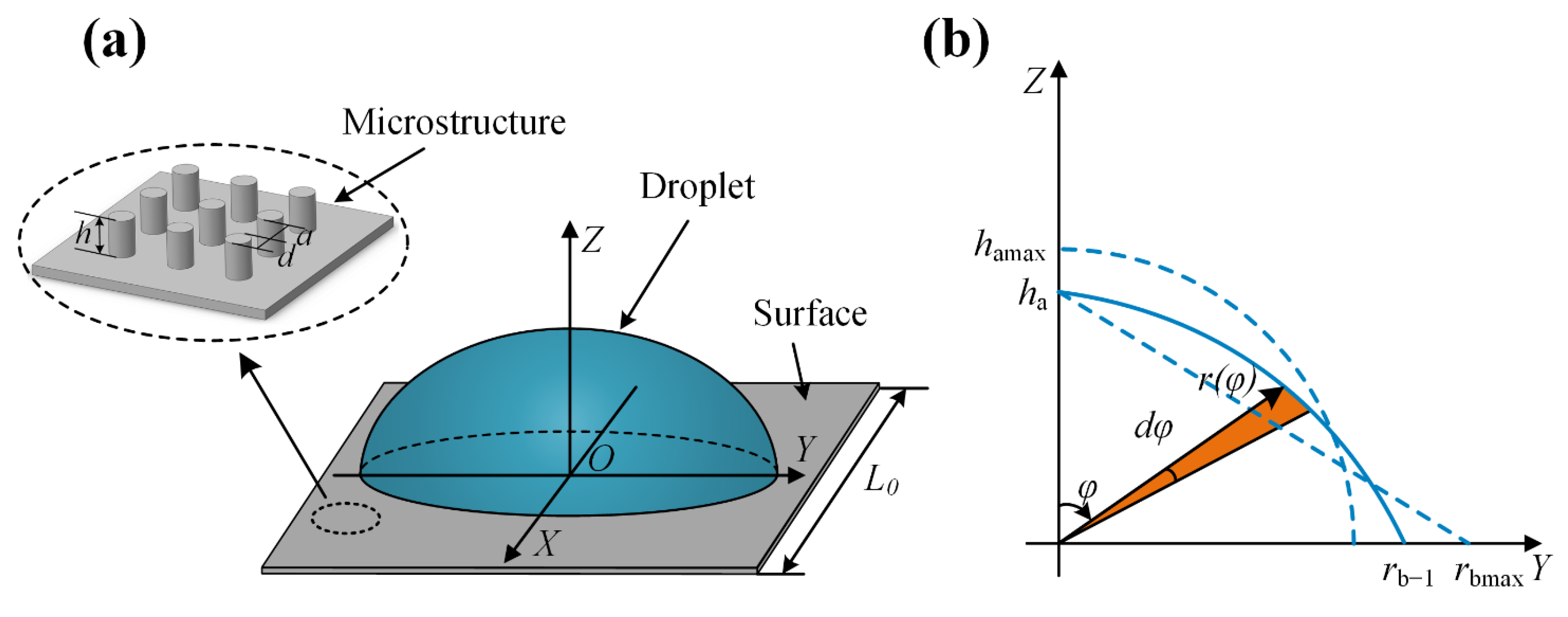
As is shown in Figure 2, the droplet on a rough horizontal surface and the relative energy of the system E w 1 can be expressed by
E w 1 = π γ lv r gh r b 1 2 cos θ e + 0 π 2 1 2 π ρ g r 4 ( φ ) sin φ cos φ + 2 π γ lv r ( φ ) sin φ r 2 ( φ ) + ( d r ( φ ) d φ ) 2 d φ
where r gh = 1 + π d h ( a + d ) 2 is the roughness factors, r b 1 the radius of contact circle on the surface, ρ the density of the liquid, g the gravitational acceleration, φ is the angle between the radius vector and the positive z-axis, r ( φ ) is the length of radius vector, γ lv is the interface tension coefficient of the liquid vapor, and θ e is the equilibrium contact angle on a smooth flat surface (for details, see Sections S3.1 and S3.2 in Supplementary Materials).
The droplet staying on a rough surface reaches the minimum relative energy. Using the finite-difference method and the nonlinear optimization algorithm, we calculated the equilibrium of relative total energy E wmin 1 and the equilibrium contact circle radius r b (for details, see Sections S3.3 and S3.4 in Supplementary Materials).
As is shown in Figure 3a, we increased the droplet volume Δ V but kept the contact circle immobile r [ n + 1 ] = r b ; the droplet has the local minimum relative energy E v + Δ v fix . Also, we increased the droplet volume Δ V and let the contact circle be mobile to get the whole minimum relative energy E v + Δ v . When the droplet keeps the contact circle immobile, the droplet has the planar potential energy Δ E = E v + Δ v fix E v + Δ v . The energy barrier E barr , which prevents the droplet’s three-phase contact line from moving, can be calculated by [37,38,39]
E barr = U l act = 2 π a + d + 2 h a + d U r b
where U is the adhesive friction between liquid and solid, and l act the actual length of the contact line. The moment Δ V increases to make Δ E = E barr , the three-phase contact circle begins to advance, and the corresponding contact angle is θ a . On the other hand, as is shown in Figure 3b, the moment Δ V decreases to make Δ E = E barr , the three-phase contact circle begins to recede, and the corresponding contact angle is θ r . (for details, see Sections S3.5–S3.8 in Supplementary Materials).

2.2. Model 2 for the Initial Front Contact Angle θ 1 0 and the Initial Rear Contact Angle θ 2 0 When a Droplet Begins to Stay on an Inclined, Hydrophilic Rough Surface

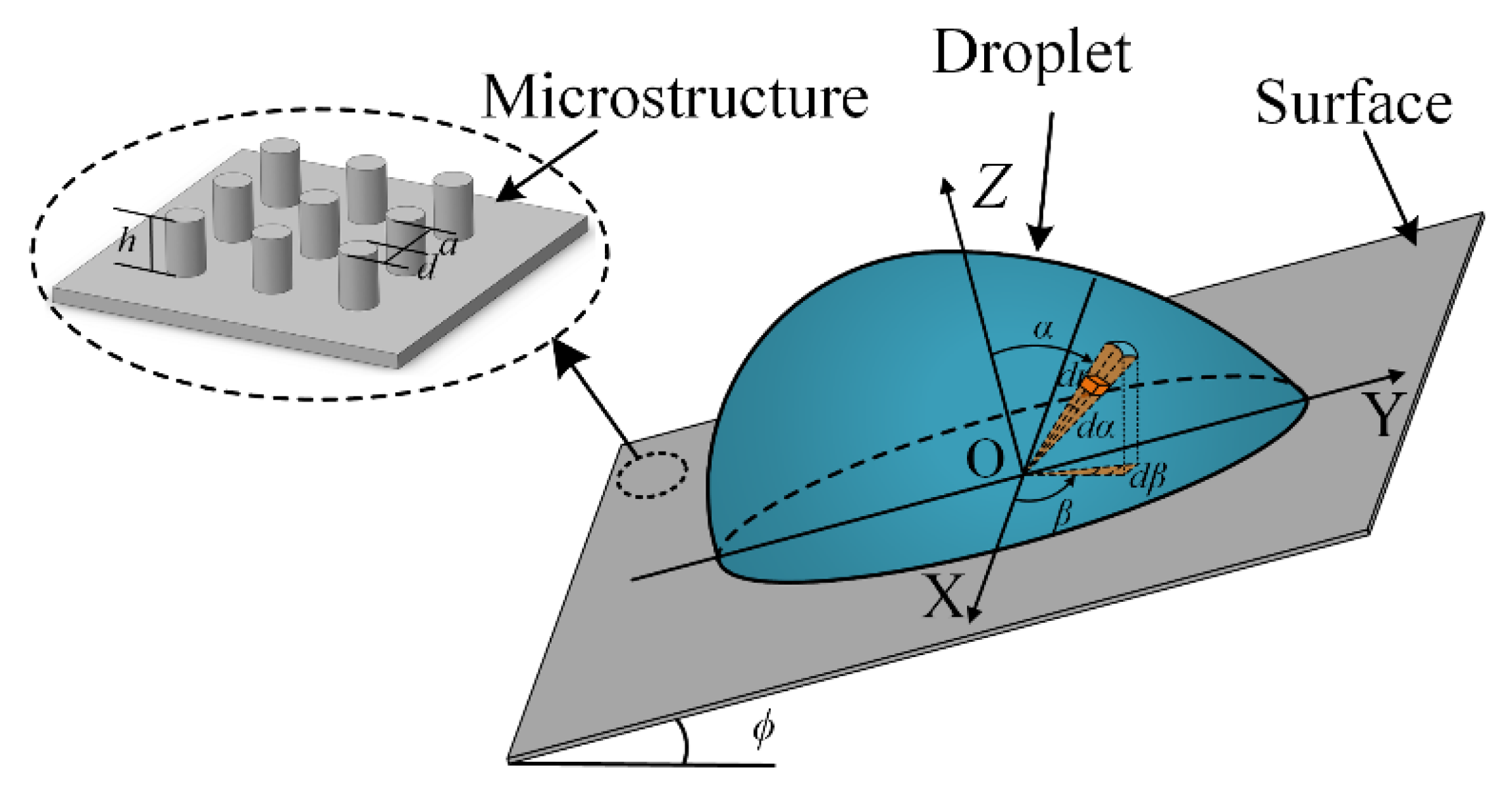
As is shown in Figure 4, the droplet initially stays on the hydrophilic rough surface inclined to the horizontal plane with a tilt angle ϕ . We selected the rough surface as the XOY plane. One point on the symmetry axis of the droplet base was defined as the origin O, the direction going ascent along the inclined surface was defined as the positive Y direction, the direction vertical to the surface and going to droplet curvature was defined as the positive Z direction, and the inside direction vertical to the YOZ plane was defined as the positive X direction. Also, we defined the vector from O to one point on the surface of the droplet as r ( β , α ) , where the azimuth angle β ( π β π ) was the angle from the positive X axis to the projection of r ( β , α ) on the XOY plane, and the zenith angle α ( 0 α π 2 ) was the angle from the positive Z axis to r ( β , α ) . The length r ( β , α ) was defined as r ( β , α ) .
The relative total energy E w 2 of the system on the inclined rough surface can be expressed as the following (for the deduction, see Sections S5.1 and S5.2 in Supplementary Materials):
E w 2 = γ lv π 2 π 2 { 0 π 2 { 1 2 γ lv ρ g r 4 ( β , α ) sin α × ( sin α sin β ) 2 + cos 2 α sin [ arccot ( sin α sin β cos α ) + ϕ ] + 2 r ( β , α ) sin α r 2 ( β , α ) + [ r ( β , α ) α ] 2 } d α r gh r 2 ( β , π 2 ) cos θ e } d β
where r ( β , π 2 ) is the length variable of the radius vector, with the zenith angle r ( β , π 2 ) .
The droplet forms its initial shape at the minimum relative energy. Using the finite-difference method and the nonlinear optimization algorithm, we simulated the initial droplet profile Ω 0 , the initial front contact angle θ 1 0 , the initial rear contact angle θ 2 0 , and the initial droplet contact line length l 0 for a droplet on the inclined hydrophilic rough surface (for details, see Sections S5.3 and S5.4 in Supplementary Materials).

2.3. Model 3 for the Dynamic Front Contact Angles θ 1 * and the Dynamic Rear Contact Angles θ 2 * When a Droplet Evolves Its Contact Line Length on an Inclined, Hydrophilic Rough Surface

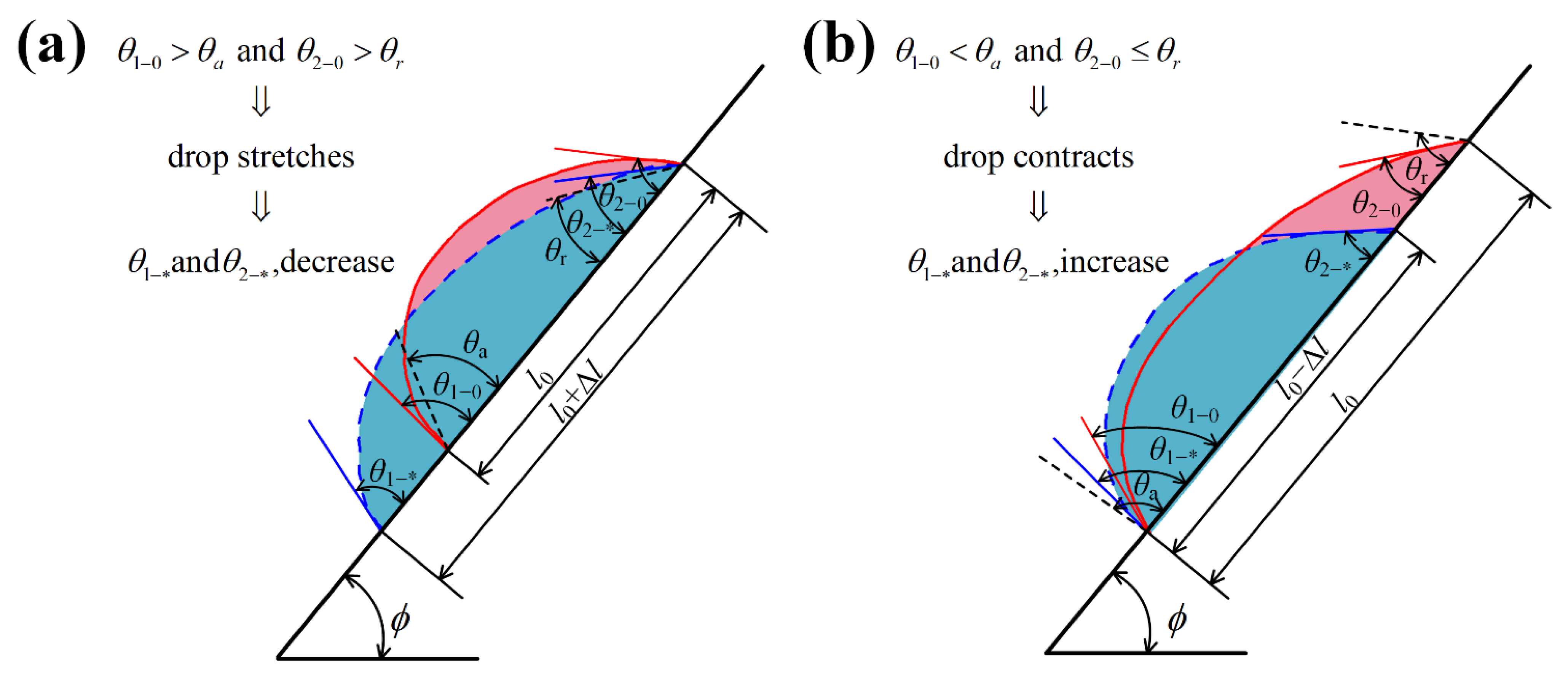
The initial state of the droplet is the whole minimum relative energy state, but it is certainly unstable if θ 1 0 θ a or θ 2 0 θ r . As is shown in Figure 5a, when θ 1 0 θ a and θ 2 0 > θ r , the front end of the droplet advances while the rear end stays pinned, leading to drop stretching. Alternatively, as shown in Figure 5b, when θ 1 0 < θ a and θ 2 0 θ r , the rear end of the droplet retracts while the front end stays pinned, leading to drop contracting. When the droplet’s contact line moves, the front contact angles and the rear contact angles will change with the change of the droplet contact line length. Every contact line length corresponds to the droplet’s dynamic front contact angle θ 1 * and the droplet’s dynamic rear contact angle θ 2 * . According to minimum energy dissipation principle, the droplet has local minimum total potential energy at every contact line length, whether stretching or contracting. In Model 3, we first set the length as l given . Second, with the constraint l given , we minimized the local total potential energy E w 2 and calculated the dynamic droplet shape Ω * , θ 1 * , and θ 2 * corresponding to l given . Using the algorithm for continuously changing the set l given , we can calculate θ 1 * and θ 2 * at every point during the droplet moving period. (for the algorithm and the flow chart, see Sections S6.1 and S6.2 in the Supplementary Materials).

2.4. The Prediction Method of the Droplet: Pinned or Sliding

When the droplet stays on an inclined, hydrophilic rough surface, we can predict the front end of the three-phase contact line, moving or not, by the comparison between θ 1 0 / θ 1 * and θ a , and predict the rear end of the three-phase contact line moving or not by the comparison between θ 2 0 / θ 2 * and θ r . According to the motion state of the front and the rear end of the three-phase contact line, we finally predict the droplet being pinned or sliding. The prediction procedure is divided into five steps, as follows (for the flow chart, see Section S7 in Supplementary Materials):
  • Step 1: We used Model 1 to calculate the advancing angle θ a and the receding angle θ r ;
  • Step 2: We used Model 2 to calculate the initial droplet profile Ω 0 , the initial droplet front contact angle θ 1 0 , and the initial droplet rear contact angle θ 2 0 ;
  • Step 3: We used θ 1 0 , θ 2 0 , θ a , and θ r to first judge the motion state of the droplet:
    (1)
    If θ 1 0 < θ a and θ 2 0 > θ r , the droplet is pinned;
    (2)
    If θ 1 0 θ a and θ 2 0 θ r , the droplet is sliding;
    (3)
    If θ 1 0 < θ a and θ 2 0 θ r , the droplet is contracting—we then went to Step 4 and further judged the motion state of the droplet;
    (4)
    If θ 1 0 θ a and θ 2 0 > θ r , the droplet is stretching—we then went to Step 5 and further judged the motion state of the droplet.
  • Step 4: For the contracting droplet, we used Model 3 to calculate out θ 1 * and θ 2 * . By constraining the contact line length l given = l 0 j δ l   ( j = 1 , 2 , 3 ) , we calculated every θ 1 * and θ 2 * corresponding to every contact line length during the droplet contracting period. Then, we calculated θ 1 * when θ 2 * = θ r . Subsequently, we made the judgment that the droplet is contracting-to-pinned if θ 1 * < θ a , and the droplet is contracting-to-sliding if θ 1 * θ a ;
  • Step 5: For the stretching droplet, we used Model 3 to calculate out θ 1 * and θ 2 * . By constraining the contact line length l given = l 0 + i δ l   ( i = 1 , 2 , 3 ) , we calculated every θ 1 * and θ 2 * corresponding to every contact line length during the droplet stretching period. Then, we calculated θ 2 * when θ 1 * = θ a . Subsequently, we made the judgment as to that the droplet is stretching-to-pinned if θ 2 * > θ r , and the droplet is stretching-to-sliding if θ 2 * θ r .

3. Experiments

3.1. SiO2 Rough Surface Fabrication and Measurement

3.1.1. SiO2 Rough Surface Fabrication

The fabrication process for SiO2 rough surfaces started from 4 inch, n-type (100) silicon wafers. Firstly, the AZ4620 photoresist was patterned for the diameter d and the periodic spacing a of the periodic circular microstructures. Secondly, deep reactive ion etching (DRIE) was processed for the height h of circular microstructures. Thirdly, the wet thermal oxidation was processed to grow 500 nm thick silicon dioxide covered on the surfaces.

3.1.2. SiO2 Rough Surface Measurement

The morphologies of SiO2 rough surfaces were measured by field emission scanning electron microscopy (FE-SEM, S4700, Hitachi, Japan). As is shown in Figure 6, the parameters of microstructures ( d , a and h ) were defined in the SEM images. The fabricated SiO2 rough surfaces were decorated by the microstructures with parameters d = 6 μm, h = 12 μm, and a = 60 μm.

3.2. Characterization of Droplet Equilibrium Contact Angles

We used an SDC-80 (Sindin, China) profile and contact angle measurement to characterize the droplet equilibrium contact angles on smooth surfaces. Droplets were set on the horizontal table. We took pictures for the equilibrium droplets and gained the equilibrium contact angles. As is shown in Figure 7, the equilibrium contact angle on the smooth PMMA surface was 74.73 ± 0.74°, and the angle for the smooth SiO2 surface was 65.57 ± 1.27°.

3.3. Characterization of Droplet Motion on Inclined Surfaces

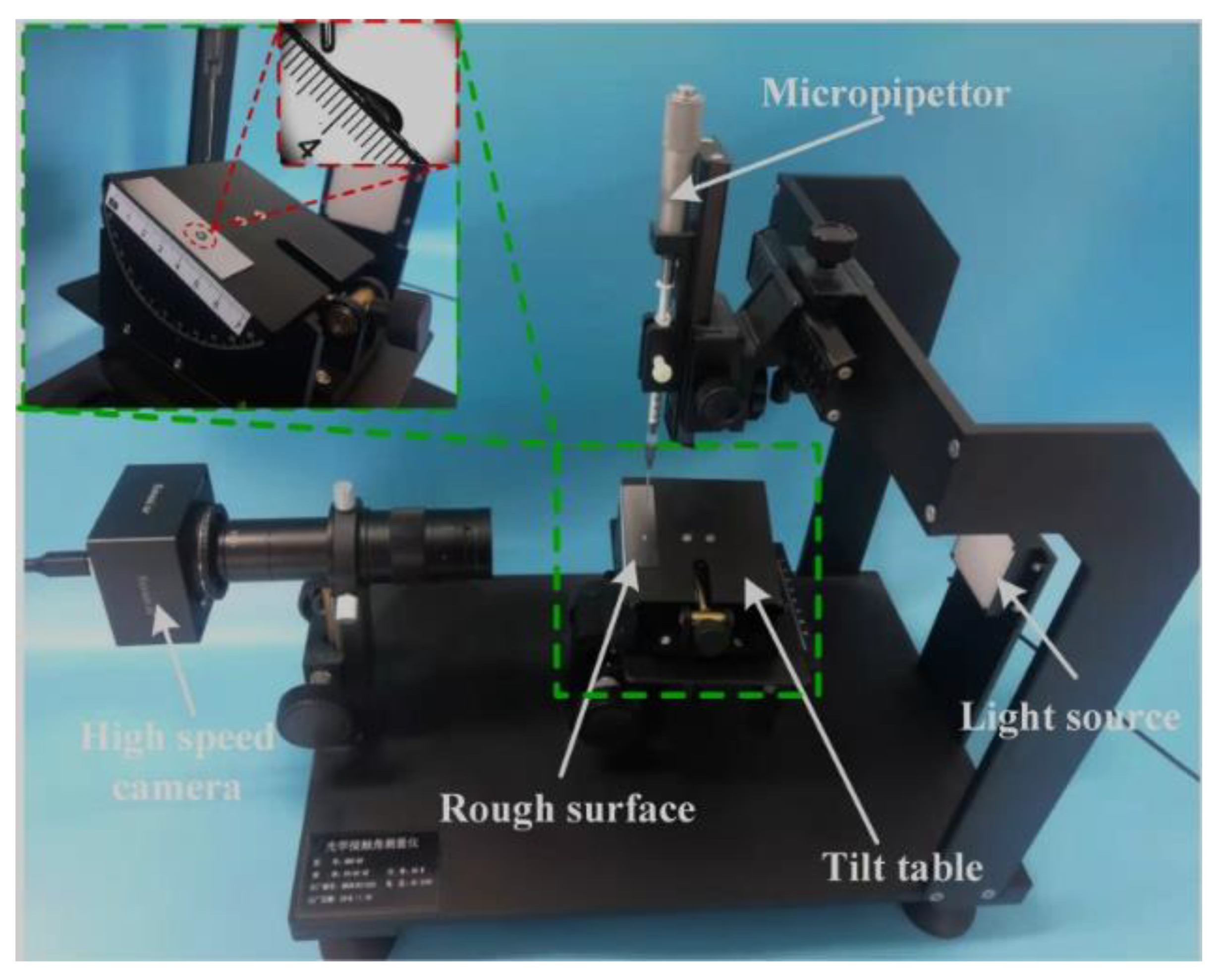
As is shown in Figure 8, also on a SDC-80, a hydrophilic rough surface was laid on an inclined table. The droplets were emitted from a needle to the rough surface. The droplet shapes and motion states were recorded by a side video camera, whose optical axis was perpendicular to the trajectory of the droplets. By different droplets’ volumes, different tilt angles, and different hydrophilic rough surfaces, we got different experimental data about droplets’ profiles ( Ω 0 , Ω * ), droplets’ front contact angles ( θ 1 0 , θ 1 * ), and droplets’ rear contact angles ( θ 2 0 , θ 2 * ).

4. Results and Discussion

4.1. The Advancing and Receding Contact Angles( θ a / θ r ) Change with the Droplet Volume

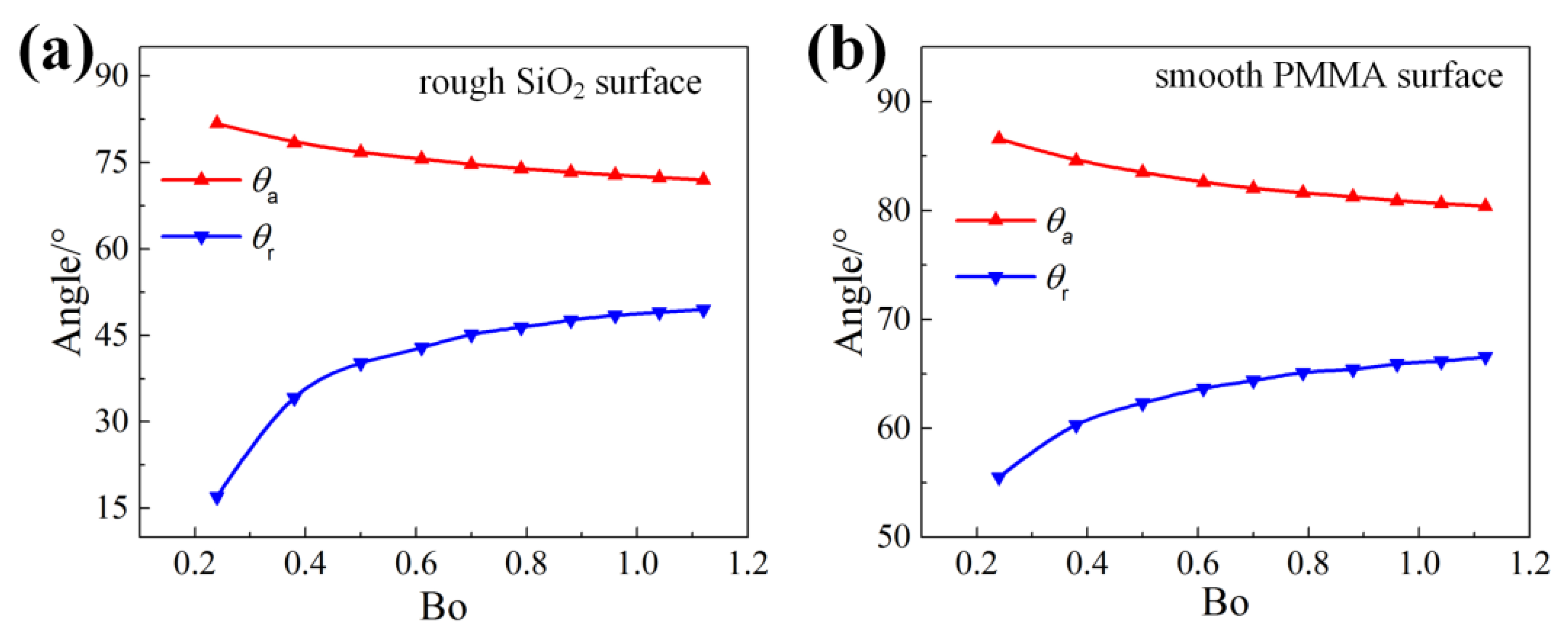
We introduced the droplet bond number (for water, B o = ( 2.73 × 10 3 ) 2 ( 3 V 4 π ) 2 3 ) to study the relationship between the droplet volume and the advancing/receding angle ( θ a / θ r ). The bigger the droplet Bond number is, the larger the droplet volume is. As shown in Figure 9, when the bond number increases, θ a goes down and θ r goes up. The so-called contact angle hysteresis is expressed by C A H = θ a θ r . The larger the volume of droplet is, the smaller CAH is, and the easier it is for the droplet to move.

4.2. The Initial Front and Rear Contact Angles ( θ 1 0 / θ 2 0 ) Change with the Droplet Volume and the Surface Tilt Angle

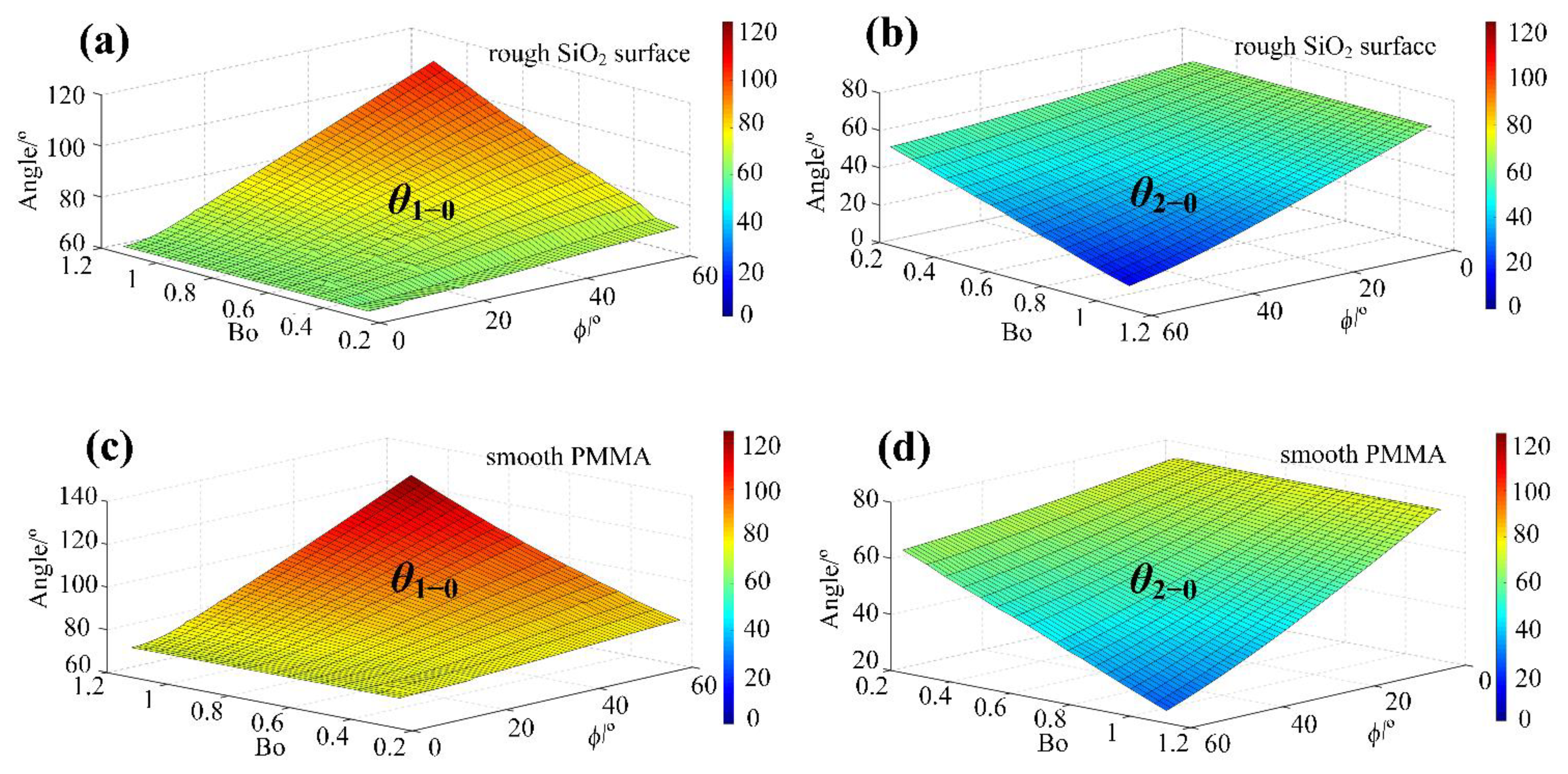
As is shown in Figure 10, with the increase of Bo, θ 1 0 goes up and θ 2 0 goes down. Also, with the increase of the φ , θ 1 0 goes up and θ 2 0 goes down.

4.3. Prediction Results Compared with Experiments

4.3.1. Droplets on an inclined Rough SiO2 Surface

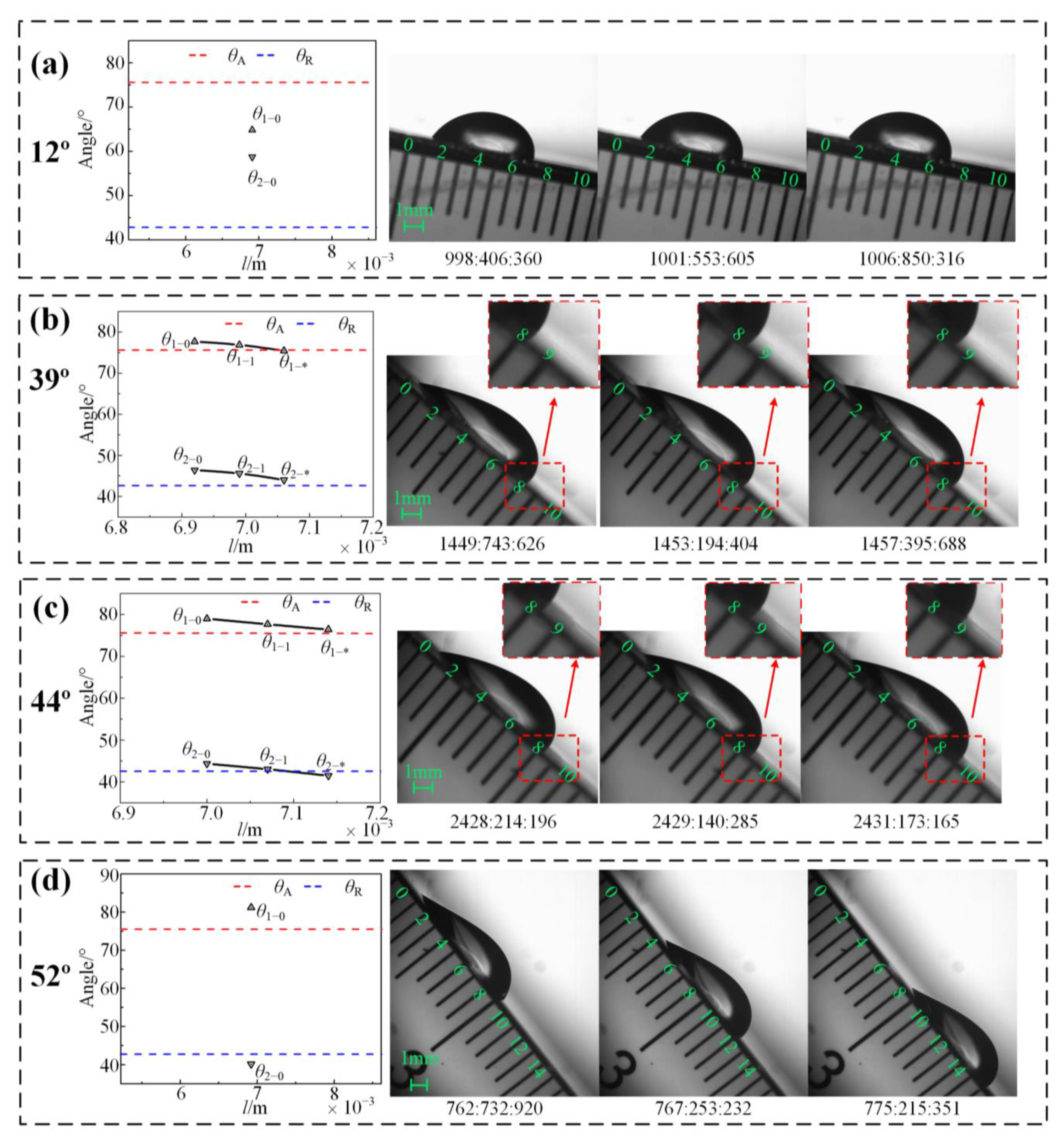
As is shown in Table 2 and Figure 11, when the tilt angles of the rough SiO2 hydrophilic surface change from 12° to 52°, the final motion states of droplets on the inclined surface change from “pinned” to “sliding”. The results from Model 1 show that the θ a and θ r of the SiO2 rough surface, decorated by microstructures ( d = 6 μm, h = 12 μm, and a = 60 μm), are 75.61° and 42.91°, respectively.
For the surface with tilt angle 12°, results from Model 2 and the prediction were θ 1 0 = 64.85° < θ a and θ 2 0 = 58.74° > θ r , respectively. We predicted that the motion state of the droplet would be “pinned” on the 12° inclined SiO2 surface.
For the surface with tilt angle 39°, the results from Models 2 and 3 and the prediction, in the droplet’s initial state, were that θ 1 0 = 77.71° > θ a and θ 2 0 = 46.43° > θ r lead to drop stretching. At one point (*), θ 1 * = 75.48° θ a and θ 2 * = 44.05° > θ r led to drop pinning. We predicted the motion state of the droplet would be “stretching-to-pinned” on a 39° inclined SiO2 surface.
For the surface with tilt angle 44°, results from Models 2 and 3 and the prediction, in the droplet’s initial state, was that θ 1 0 = 79.01° > θ a and θ 2 0 = 44.39° > θ r lead to drop stretching, respectively. At one point *, θ 1 * = 76.42° > θ a and θ 2 * = 41.51° < θ r lead to drop sliding. We predicted the motion state of droplet is “stretching-to-sliding” on the 44° inclined SiO2 surface.
For the surface with tilt angle 52°, results from Model 2 and the prediction in the droplet’s initial state were θ 1 0 = 81.21° > θ a and θ 2 0 = 40.19° < θ r , respectively. We predicted the motion state of the droplet is “sliding” on the 52° inclined SiO2 surface.
We did experiments to verify predictions. Experimental results showed that when the surfaces tilt angles were in the range 40° < ϕ < 42°, the motion state of the droplet is “contracting-to-pinned”, which has 1~2° errors with the prediction results 39° ≤ ϕ < 44°. It was showed that the experimental data agreed well with the prediction results (for video, see Video S1–S4 in the Supplementary Materials).

4.3.2. Droplets on an Inclined, Smooth PMMA Surface

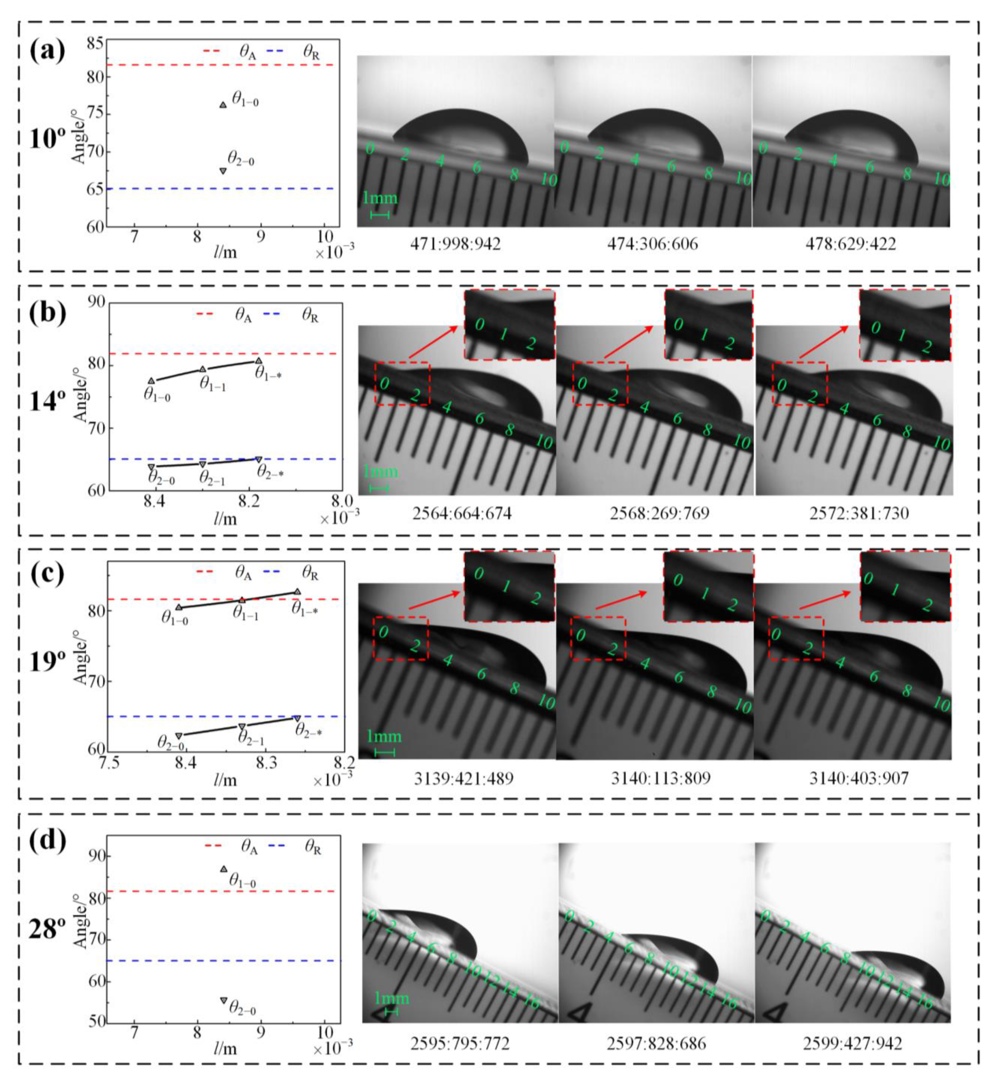
As is shown in Table 3 and Figure 12, when the tilt angles of the smooth PMMA hydrophilic surface change from 10° to 28°, the final motion states of droplets on the inclined surface change from “pinned” to “sliding”. Results from Model 1 indicate that the θ a and θ r of the smooth PMMA surface are 81.62° and 65.10°, respectively.
For the surface with tilt angle 10°, the results from Model 2 and the prediction were that θ 1 0 = 76.20° < θ a and θ 2 0 = 67.56° > θ r , respectively. We predicted that the motion state of droplet is “pinned” on the 10° inclined PMMA surface.
For the surface with tilt angle 14°, the results from Models 2 and 3 and the prediction, in the droplet’s initial state, were θ 1 0 = 77.48° < θ a and θ 2 0 = 63.89° < θ r , leading to drop contracting, respectively. At one point (*), θ 1 * = 80.71° < θ a and θ 2 * = 65.13° θ r lead to drop pinning. We predicted the motion state of droplet would be “contracting-to-pinned” on the 14° inclined PMMA surface.
For the surface with tilt angle 19°, the results from Models 2 and 3 and the prediction, in the droplet’s initial state, was that θ 1 0 = 80.42° < θ a and θ 2 0 = 62.37° < θ r , leading to drop contracting, respectively. At one point (*), θ 1 * = 82.64° > θ a and θ 2 * = 64.86° < θ r , leading to drop sliding. We predicted the motion state of droplet is “contracting-to-sliding” on the 19°, inclined PMMA surface.
For the surface with a tilt angle of 28°, the results from Model 2 and the prediction, in the droplet’s initial state, were that θ 1 0 = 86.85° > θ a and θ 2 0 = 55.71° < θ r , respectively. We predicted the motion state of droplet would be “sliding” on the 28° inclined PMMA surface.
We did experiments to verify our predictions. Experimental results showed that when the surface tilt angles are in the range 19° < ϕ < 23°, the motion state of droplet is “contracting-to-pinned”; this has 4~5° errors, with prediction results at 14° < ϕ < 19°. It was shown that the experimental data agreed well with the prediction results (for video, see Video S5–S8 in the Supplementary Materials).

5. Conclusions

All this work contributes to understanding the wetting and the spreading properties of a droplet on an inclined, hydrophilic rough surface, both theoretically and practically. In this paper, we used the minimum free energy theory, the minimum energy dissipation theory, and nonlinear optimization algorithms to model and calculate the advancing/receding contact angles ( θ a / θ r ), the initial front/rear contact angles ( θ 1 0 / θ 2 0 ), and the dynamic front/rear contact angles ( θ 1 * / θ 2 * ) of a droplet on an inclined hydrophilic rough surface. Also, we predicted the droplet motion state by comparing θ 1 0 ( θ 2 0 ) and θ 1 * , ( θ 2 * ) with θ a ( θ r ). Additionally, experiments were done to verify the predictions. The experimental data were found to agree with the predictions. Our method can be used to optimize the hydrophilic rough surface, which can be used to exploit devices like variable-focus lances, electronic displays, and micro-fluidic systems.

Supplementary Materials

The following are available online at https://www.mdpi.com/article/10.3390/app11093734/s1, Figure S1: a profile of the half-droplet, Figure S2: the flow chart of “subprofile”, Figure S3: the flow chart of “subfixcircle”, Figure S4: the flow chart of “subadvrec”, Figure S5: the droplet on the inclined hydrophilic rough surface, Figure S6: the flow chart of “subtiltinitial”, Figure S7. the flow chart of “subtiltchange”, Figure S8. the flow chart of “prediction”. Video S1: droplets pinned on rough SIO2 surface, Video S2: droplets stretching-to-pinned on rough SIO2 surface, Video S3:droplets stretching-to-sliding on rough SIO2 surface, Video S4:droplets sliding on rough SIO2 surface, Video S5: droplets pinned on smooth PMMA surface, Video S6: droplets contracting-to-pinned on smooth PMMA surface, Video S7:droplets contracting -to-sliding on smooth PMMA surface, Video S8:droplets sliding on smooth PMMA surface.(1) Text Supplementary Materials for the derivation and calculation of models and the prediction method. (2) Video Supplementary Materials, including the movies of drop motion.

Author Contributions

Formal analysis, L.J., C.S., Z.Z., and J.H.; methodology, Y.B.; software, Y.G. and Y.B.; writing—original draft, J.D.; writing—review and editing, J.D. and Y.G. All authors have read and agreed to the published version of the manuscript.

Funding

This work is supported by the National Natural Science Foundation of China, under grant 51875527; the National Natural Science Foundation of China, under grant 52075492; the Project of Outstanding Youth Fund in Zhejiang Province of China, under grant LR18E050002; and the National Outstanding Youth Science Fund Project of the National Natural Science Foundation of China, under grant 52006195.

Institutional Review Board Statement

Not applicable.

Informed Consent Statement

Not applicable.

Data Availability Statement

Data sharing not applicable.

Acknowledgments

We are grateful to the anonymous reviewers for constructive comments that improved the quality of the work.

Conflicts of Interest

The authors declare no competing financial interests.

References

  1. Ye, Y.; Liu, Z.; Liu, W.; Zhang, D.; Zhao, H.; Wang, L.; Li, X. Superhydrophobic oligoaniline-containing electroactive silica coating as pre-process coating for corrosion protection of carbon steel. Chem. Eng. J. 2018, 348, 940–951. [Google Scholar] [CrossRef]
  2. Wang, K.; Hou, D.; Wang, J.; Wang, Z.; Tian, B.; Liang, P. Hydrophilic surface coating on hydrophobic PTFE membrane for robust anti-oil-fouling membrane distillation. Appl. Surf. Sci. 2018, 450, 57–65. [Google Scholar] [CrossRef]
  3. Eykens, L.; Rose, K.; Dubreuil, M.; De Sitter, K.; Dotremont, C.; Pinoy, L.; Van Der Bruggen, B. Functionalization of a Hydrophilic Commercial Membrane Using Inorganic-Organic Polymers Coatings for Membrane Distillation. Appl. Sci. 2017, 7, 637. [Google Scholar] [CrossRef] [Green Version]
  4. Yang, W.; Huang, H.; Yan, W. Thermal Lattice Boltzmann Simulation of Evaporating Thin Liquid Film for Vapor Generation. Appl. Sci. 2018, 8, 798. [Google Scholar] [CrossRef] [Green Version]
  5. Esmaeilnezhad, E.; Karimian, M.; Choi, H.J. Synthesis and thermal analysis of hydrophobic iron oxide nanoparticles for improving in-situ combustion efficiency of heavy oils. J. Ind. Eng. Chem. 2019, 71, 402–409. [Google Scholar] [CrossRef]
  6. Gunay, A.A.; Sett, S.; Oh, J.; Miljkovic, N. Steady Method for the Analysis of Evaporation Dynamics. Langmuir 2017, 33, 12007–12015. [Google Scholar] [CrossRef]
  7. Sun, Q.; Wang, D.; Li, Y.; Zhang, J.; Ye, S.; Cui, J.; Chen, L.; Wang, Z.; Butt, H.-J.; Vollmer, D.; et al. Surface charge printing for programmed droplet transport. Nat. Mater. 2019, 18, 936–941. [Google Scholar] [CrossRef] [Green Version]
  8. Wijshoff, H. Drop dynamics in the inkjet printing process. Curr. Opin. Colloid Interface Sci. 2018, 36, 20–27. [Google Scholar] [CrossRef]
  9. Chauhan, P.; Kumar, A.; Bhushan, B. Self-cleaning, stain-resistant and anti-bacterial superhydrophobic cotton fabric prepared by simple immersion technique. J. Colloid Interface Sci. 2019, 535, 66–74. [Google Scholar] [CrossRef]
  10. Li, J.; Wei, Y.; Huang, Z.; Wang, F.; Yan, X.; Wu, Z. Electrohydrodynamic behavior of water droplets on a horizontal super hydrophobic surface and its self-cleaning application. Appl. Surf. Sci. 2017, 403, 133–140. [Google Scholar] [CrossRef] [Green Version]
  11. Li, Q.; Liu, H.; Zhang, S.; Zhang, D.; Liu, X.; He, Y.; Mi, L.; Zhang, J.; Liu, C.; Shen, C.; et al. Superhydrophobic Electrically Conductive Paper for Ultrasensitive Strain Sensor with Excellent Anticorrosion and Self-Cleaning Property. ACS Appl. Mater. Interfaces 2019, 11, 21904–21914. [Google Scholar] [CrossRef] [PubMed]
  12. Dai, X.; Sun, N.; Nielsen, S.O.; Stogin, B.B.; Wang, J.; Yang, S.; Wong, T.-S. Hydrophilic directional slippery rough surfaces for water harvesting. Sci. Adv. 2018, 4, eaaq0919. [Google Scholar] [CrossRef] [Green Version]
  13. Knapczyk-Korczak, J.; Ura, D.P.; Gajek, M.; Marzec, M.M.; Berent, K.; Bernasik, A.; Chiverton, J.P.; Stachewicz, U. Fiber-Based Composite Meshes with Controlled Mechanical and Wetting Properties for Water Harvesting. ACS Appl. Mater. Interfaces 2019, 12, 1665–1676. [Google Scholar] [CrossRef]
  14. Lu, J.; Ngo, C.-V.; Singh, S.C.; Yang, J.; Xin, W.; Yu, Z.; Guo, C. Bioinspired Hierarchical Surfaces Fabricated by Femtosecond Laser and Hydrothermal Method for Water Harvesting. Langmuir 2019, 35, 3562–3567. [Google Scholar] [CrossRef]
  15. Bokharaei, M.; Saatchi, K.; Häfeli, U.O. A single microfluidic chip with dual surface properties for protein drug delivery. Int. J. Pharm. 2017, 521, 84–91. [Google Scholar] [CrossRef]
  16. Liu, X.; Li, H.; Jia, W.; Chen, Z.; Xu, D. Selection of aptamers based on a protein microarray integrated with a microfluidic chip. Lab Chip 2016, 17, 178–185. [Google Scholar] [CrossRef]
  17. Biočanin, M.; Bues, J.; Dainese, R.; Amstad, E.; Deplancke, B. Simplified Drop-seq workflow with minimized bead loss using a bead capture and processing microfluidic chip. Lab Chip 2019, 19, 1610–1620. [Google Scholar] [CrossRef] [Green Version]
  18. Marsh, J.A.; Garoff, S. Dynamic contact angles and hydrodynamics near a moving contact line. Phys. Rev. Lett. 1993, 70, 2778–2781. [Google Scholar] [CrossRef]
  19. Dussan, E.B.; Chow, R.T.-P. On the ability of drops or bubbles to stick to non-horizontal surfaces of solids. J. Fluid Mech. 1983, 137, 1–29. [Google Scholar] [CrossRef]
  20. Ngan, C.G. On the dynamics of liquid spreading on solid surfaces. J. Fluid Mech. 1989, 209, 191. [Google Scholar] [CrossRef]
  21. Dussan, E.B. On the ability of drops or bubbles to stick to non-horizontal surfaces of solids. Part 2. Small drops or bubbles having contact angles of arbitrary size. J. Fluid Mech. 1985, 151. [Google Scholar] [CrossRef]
  22. Varagnolo, S.; Ferraro, D.; Fantinel, P.; Pierno, M.; Mistura, G.; Amati, G.; Biferale, L.; Sbragaglia, M. Stick-Slip Sliding of Water Drops on Chemically Heterogeneous Surfaces. Phys. Rev. Lett. 2013, 111, 066101. [Google Scholar] [CrossRef] [Green Version]
  23. Xu, H.; Clarke, A.; Rothstein, J.; Poole, R. Viscoelastic drops moving on hydrophilic and superhydrophobic surfaces. J. Colloid Interface Sci. 2018, 513, 53–61. [Google Scholar] [CrossRef]
  24. Yonemoto, Y.; Suzuki, S.; Uenomachi, S.; Kunugi, T. Sliding behaviour of water-ethanol mixture droplets on inclined low-surface-energy solid. Int. J. Heat Mass Transf. 2018, 120, 1315–1324. [Google Scholar] [CrossRef]
  25. Bommer, S.; Scholl, H.; Seemann, R.; Kanhaiya, K.; Sheraton, M.V.; Verma, N. Depinning of Drops on Inclined Smooth and Topographic Surfaces: Experimental and Lattice Boltzmann Model Study. Langmuir 2014, 30, 11086–11095. [Google Scholar] [CrossRef]
  26. Furmidge, C. Studies at phase interfaces. I. The sliding of liquid drops on solid surfaces and a theory for spray retention. J. Colloid Sci. 1962, 17, 309–324. [Google Scholar] [CrossRef]
  27. Miwa, M.; Nakajima, A.; Fujishima, A.; Hashimoto, K.; Watanabe, T. Effects of the Surface Roughness on Sliding Angles of Water Droplets on Superhydrophobic Surfaces. Langmuir 2000, 16, 5754–5760. [Google Scholar] [CrossRef]
  28. Man, X.; Doi, M. Ring to Mountain Transition in Deposition Pattern of Drying Droplets. Phys. Rev. Lett. 2016, 116, 066101. [Google Scholar] [CrossRef] [Green Version]
  29. Xu, X.; Di, Y.; Doi, M. Variational method for liquids moving on a substrate. Phys. Fluids 2016, 28, 087101. [Google Scholar] [CrossRef]
  30. Doi, M. Onsager’s variational principle in soft matter. J. Phys. Condens. Matter 2011, 23, 284118. [Google Scholar] [CrossRef] [PubMed]
  31. Maglio, M.; Legendre, D. Numerical Simulation of Sliding Drops on an Inclined Solid Surface. In Computational and Experimental Fluid Mechanics with Applications to Physics, Engineering and the Environment; Sigalotti, L.D.G., Klapp, J., Sira, E., Eds.; Environmental Science and Engineering; Springer International Publishing: Cham, Switzerland, 2014; pp. 47–69. [Google Scholar]
  32. Dupont, J.-B.; Legendre, D. Numerical simulation of static and sliding drop with contact angle hysteresis. J. Comput. Phys. 2010, 229, 2453–2478. [Google Scholar] [CrossRef]
  33. Legendre, D.; Maglio, M. Numerical simulation of spreading drops. Colloids Surf. A Physicochem. Eng. Asp. 2013, 432, 29–37. [Google Scholar] [CrossRef] [Green Version]
  34. Luo, M.; Gupta, R.; Frechette, J. Modulating Contact Angle Hysteresis to Direct Fluid Droplets along a Homogenous Surface. ACS Appl. Mater. Interfaces 2012, 4, 890–896. [Google Scholar] [CrossRef]
  35. Peng, Z.; Moghtaderi, B.; Doroodchi, E. Suspension stability of slurry Taylor flow: A theoretical analysis. Chem. Eng. Sci. 2017, 174, 459–471. [Google Scholar] [CrossRef]
  36. Peng, Z.; Gai, S.; Barma, M.; Rahman, M.M.; Moghtaderi, B.; Doroodchi, E. Experimental study of gas-liquid-solid flow characteristics in slurry Taylor flow-based multiphase microreactors. Chem. Eng. J. 2021, 405, 126646. [Google Scholar] [CrossRef]
  37. Whyman, G.; Bormashenko, E.; Stein, T. The rigorous derivation of Young, Cassie–Baxter and Wenzel equations and the analysis of the contact angle hysteresis phenomenon. Chem. Phys. Lett. 2008, 450, 355–359. [Google Scholar] [CrossRef]
  38. Bormashenko, E.; Musin, A.; Zinigrad, M. Evaporation of droplets on strongly and weakly pinning surfaces and dynamics of the triple line. Colloids Surf. A Physicochem. Eng. Asp. 2011, 385, 235–240. [Google Scholar] [CrossRef]
  39. Dong, J.; Jin, Y.; Dong, H.; Liu, J.; Ye, S. Numerical Study for a Large-Volume Droplet on the Dual-Rough Surface: Apparent Contact Angle, Contact Angle Hysteresis, and Transition Barrier. Langmuir 2018, 34, 8119–8127. [Google Scholar] [CrossRef]
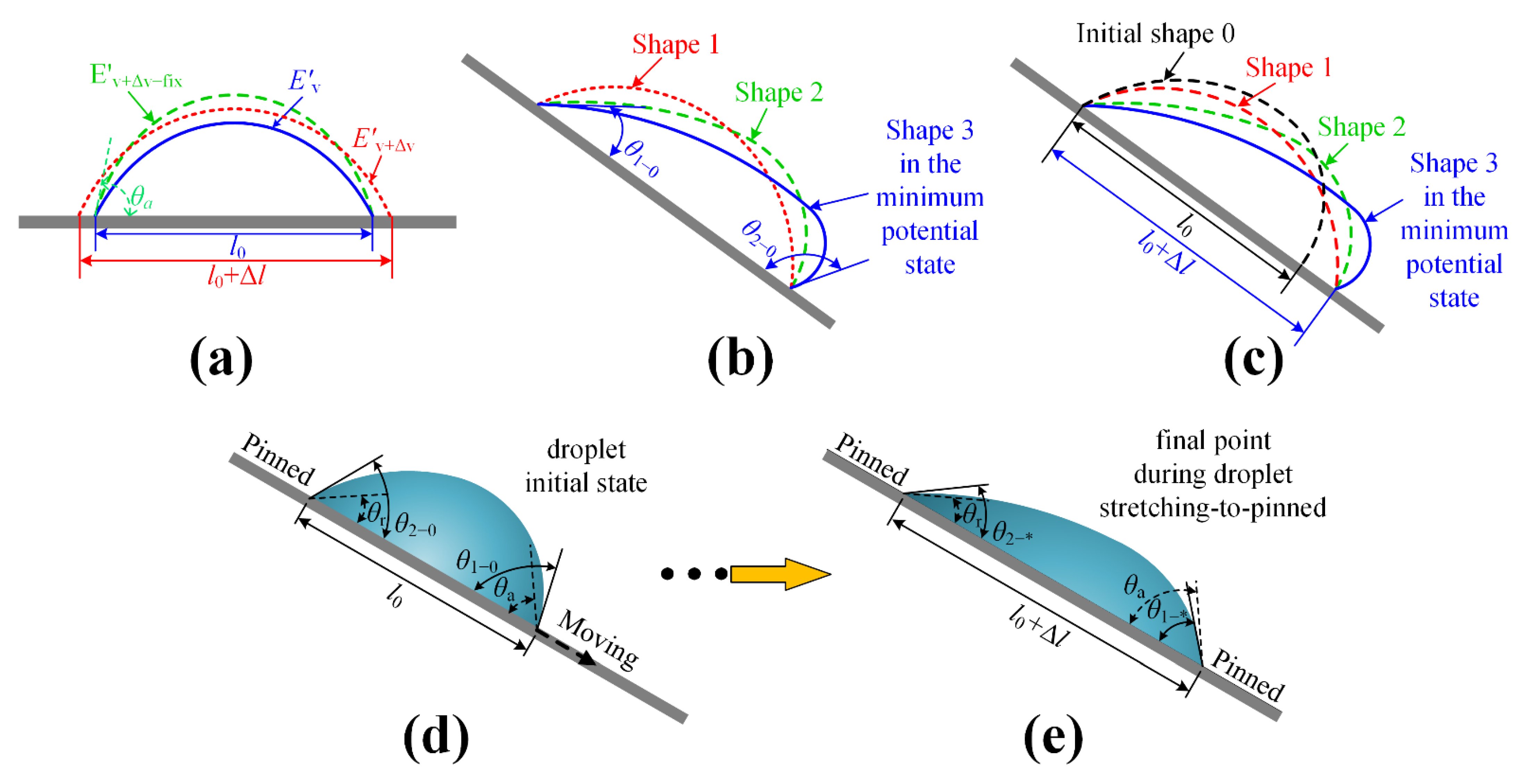
Figure 1. A simple description for methods of Models 1–3 and the predictions. (a) Model 1 description: when the droplet volume increases from V to V + Δ V , but the contact line is fixed, the droplet has the potential energy Δ E = E v + Δ v fix E v + Δ v . When Δ E = E barr , the contact angle corresponding to the fixed contact line is regarded as θ a . (b) Model 2 description: shapes 1–3 represent possible droplet shapes when the droplet is initially placed on the inclined surface. Shape 3 ( Ω 0 ) is in the minimum energy state; θ 1 0 / θ 2 0 can be gained by Ω 0 . (c) Model 3 description: shapes 1–3 represent possible droplet shapes on one point of the droplet stretching motion. Shape 3 ( Ω * ) is in the minimum energy state. θ 1 * / θ 2 * can be gained by Ω * . (d,e) The prediction description. (d) In the initial droplet state, θ 1 0 > θ a and θ 2 0 > θ r , we predicted the front contact line moving and the rear contact line pinned. (e) In one point of droplet motion, θ 1 * < θ a and θ 2 * > θ r , both the front and the rear contact lines are pinned, the droplet will finally be pinned, and the motion state is predicted as “stretching-to-pinned”.
Applsci 11 03734 g001
Figure 2. The sketch of calculation for the relative energy of the system E wmin 1 . (a) A droplet stays on a horizontal rough surface decorated by circular pillars; h is the height of the pillar, d is the diameter of the pillar, and a is the periodic spacing of pillars. (b) A profile of the half-droplet; h a is the distance between the top of the droplet and the surface, h amax is the maximum h a , r b 1 is the radius of contact circle on the surface, r bmax is the maximum r b 1 , and φ ( 0 φ π 2 ) is the angle between the radius vector r ( φ ) and the positive z-axis.
Applsci 11 03734 g002
Figure 3. The sketch of calculations for θ a and θ r . (a) The moment the droplet volume increases to make the contact circle advance, and the ACA is θ a . (b) The moment the droplet volume decreases to make the contact circle recede, the ACA is θ r .
Applsci 11 03734 g003
Figure 4. The droplet on the inclined, hydrophilic rough surface.
Applsci 11 03734 g004
Figure 5. The changes of θ 1 * and θ 2 * in droplet evolution process. (a) θ 1 0 θ a and θ 2 0 > θ r : the drop stretches, and θ 1 * and θ 2 * both decrease. (b) θ 1 0 < θ a and θ 2 0 θ r : the drop contracts, and θ 1 * and θ 2 * both increase.
Applsci 11 03734 g005
Figure 6. SEM pictures of SiO2 rough surfaces. (a) The whole picture of the SiO2 rough surface. (b) The periodic spacing a of the circular microstructures. (c) The diameter d and the height h of the circular microstructures.
Applsci 11 03734 g006
Figure 7. Equilibrium contact angles of water droplets (a) on the smooth PMMA surface and (b) on the smooth SiO2 surface.
Applsci 11 03734 g007
Figure 8. Schematic of the experimental apparatus.
Applsci 11 03734 g008
Figure 9. The relationship between the advancing/receding angle ( θ a / θ r ) and the droplet bond number. (a) The SiO2 rough surface with the microstructures ( d = 6 μm, h = 12 μm, and a = 60 μm). (b) The smooth PMMA surface.
Applsci 11 03734 g009
Figure 10. Changes of front contact angle θ 1 0 and rear contact angle θ 2 0 with bond number Bo and tilt angle φ . (a,b) the SiO2 rough surface ( d = 6 μm, h = 12 μm and a = 60 μm). (c,d) The smooth PMMA surface.
Applsci 11 03734 g010
Figure 11. The simulations, predictions, and experiments of droplets on an inclined rough SiO2 surface. The microstructure parameters are d = 6 μm, h = 12 μm, and a = 60 μm; V = 40 μL. (a) 12°, (b) 39°, (c) 44°, and (d) 52°.
Applsci 11 03734 g011
Figure 12. The simulations, predictions, and experiments of droplets on the inclined, smooth PMMA surface, where V = 60 μL: (a) 10°, (b) 14°, (c) 19°, and (d) 28°.
Applsci 11 03734 g012
Table 1. Numerical results and motion state predictions for the droplet on an inclined, rough SiO2 surface.
Surface Tilt Angle/° Droplet Volume/μL θ a θ r θ 1 0 θ 2 0 Initial Motion State θ 1 * θ 2 * Final Motion State
394075.6142.9177.7146.43stretching75.4844.05stretching-to-pinned
Table 2. Numerical results and motion state predictions of droplets on the inclined rough SiO2 surface a.
Tilt Angle/° θ a θ r θ 1 0 θ 2 0 Initial Motion State θ 1 * θ 2 * Final Motion State
1275.6142.9164.8558.74Pinned--Pinned
3975.6142.9177.7146.43Stretching75.4844.05Stretching-to-pinned
4475.6142.9179.0144.39Stretching76.4241.51Stretching-to-sliding
5275.6142.9181.2140.19Sliding--Sliding
a Microstructure parameters are d = 6 μm, h = 12 μm, and a = 60 μm; U = 2.3 × 10⁻⁵ (N); the volume is 40 μL; γlv = 72.75 mN/m; and θ e = 65.57°.
Table 3. Numerical results and motion state predictions of droplets on the inclined, smooth PMMA surface a.
Tilt Angle/° θ a θ r θ 1 0 θ 2 0 Initial Motion State θ 1 * θ 2 * Final Motion State
1081.6265.1076.2067.56Pinned--Pinned
1481.6265.1077.4863.89Contracting80.7165.13Contracting-to-pinned
1981.6265.1080.4262.37Contracting82.6464.86Contracting-to-sliding
2881.6265.1086.8555.71Sliding--Sliding
aU = 2.1 × 10⁻⁵ (N), the volume is 60 μL, γlv = 72.75 mN/m, and θ e = 74.73°.
Publisher’s Note: MDPI stays neutral with regard to jurisdictional claims in published maps and institutional affiliations.