
Staircase Detection, Characterization and Approach Pipeline for Search and Rescue Robots

 , , and
Abstract
:1. Introduction
2. Materials and Methods
2.1. Dataset
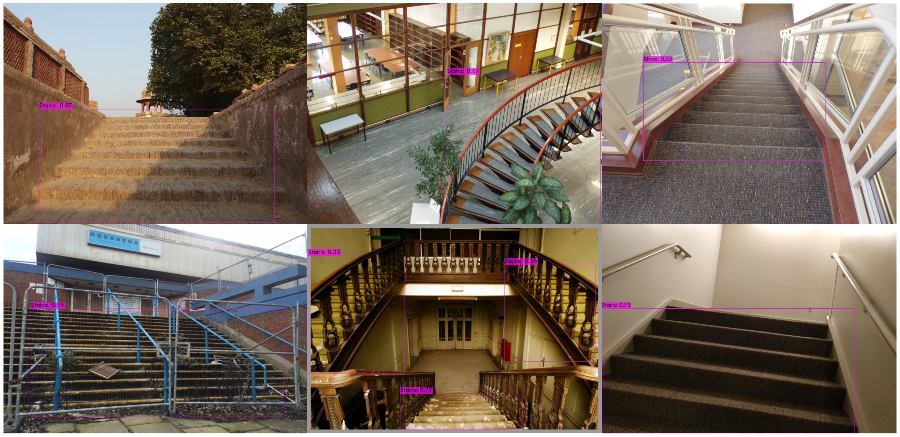
2.2. YOLOv4
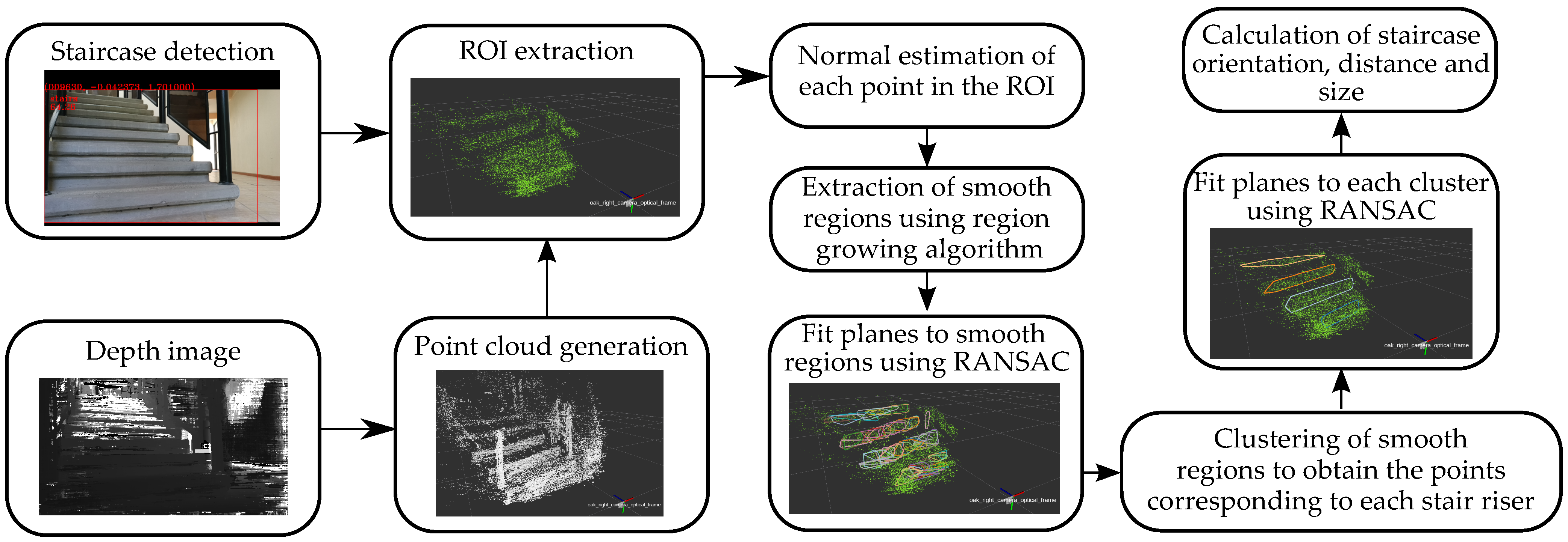
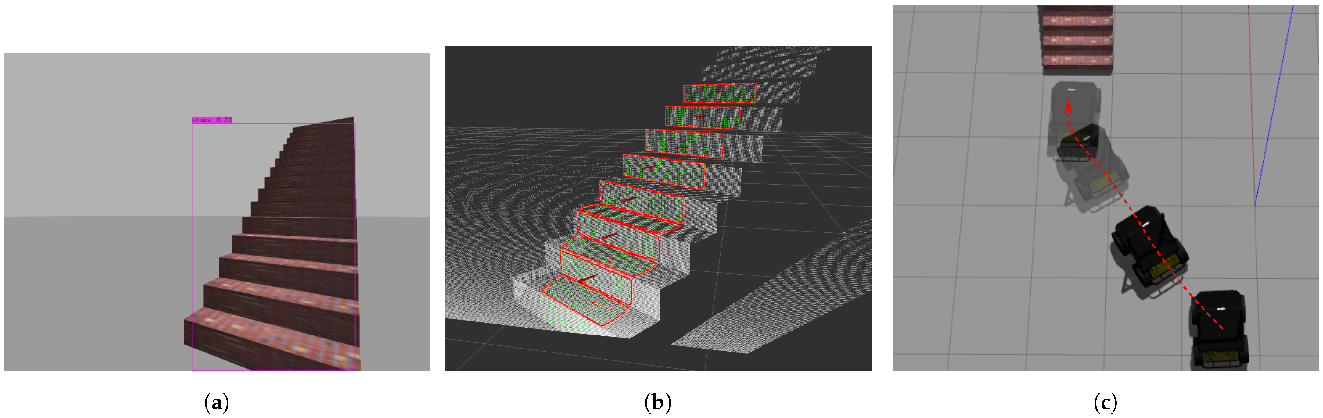
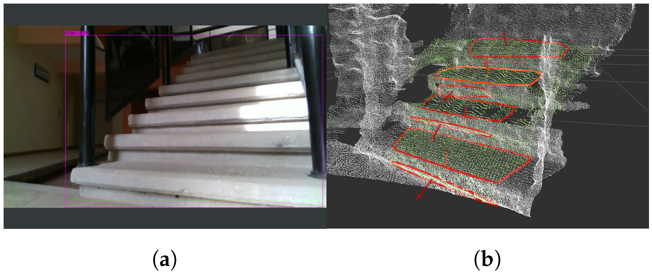
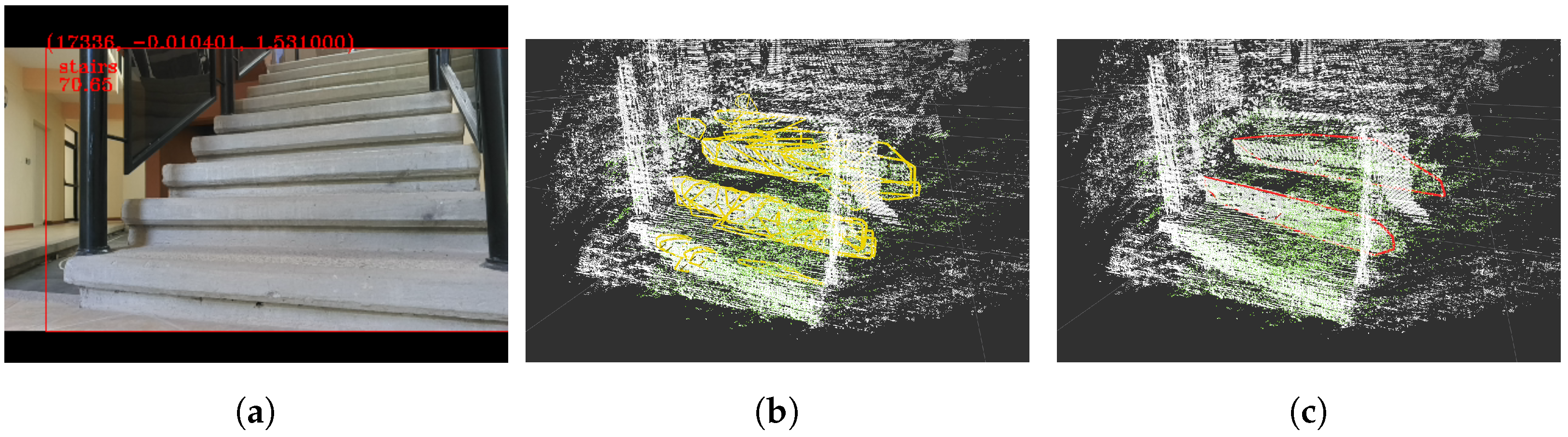
2.3. Staircase Plane Extraction and Characterization
- The angle between planes fitted to each region.
- The vertical distance between the centroid of each region.
- The lateral distance between the centroid of each region.
| Algorithm 1. Algorithm to cluster smooth surfaces |
| Inputs: Point cloud of centroids = , point normals = , |
| clusters of smooth regions = , neighbor finding function , |
| number of directions from initial seed to search for |
| Outputs: Clusters of stair risers |
| while do |
| Nearest neighbors of reference seed |
| current seed |
| initial |
| ▹ remove seed from initial point cloud |
| Indexes of nearest neighbors of current seed |
| while do |
| angle between and |
| distance between and in z direction |
| distance between and in y direction |
| if and and then |
| points of |
| points of |
| current seed |
| ▹ remove seed from initial point cloud |
| Indexes of nearest neighbors of current seed |
| else |
| if and then |
| end if |
| end if |
| end while |
| if size( then |
| end if |
| end while |
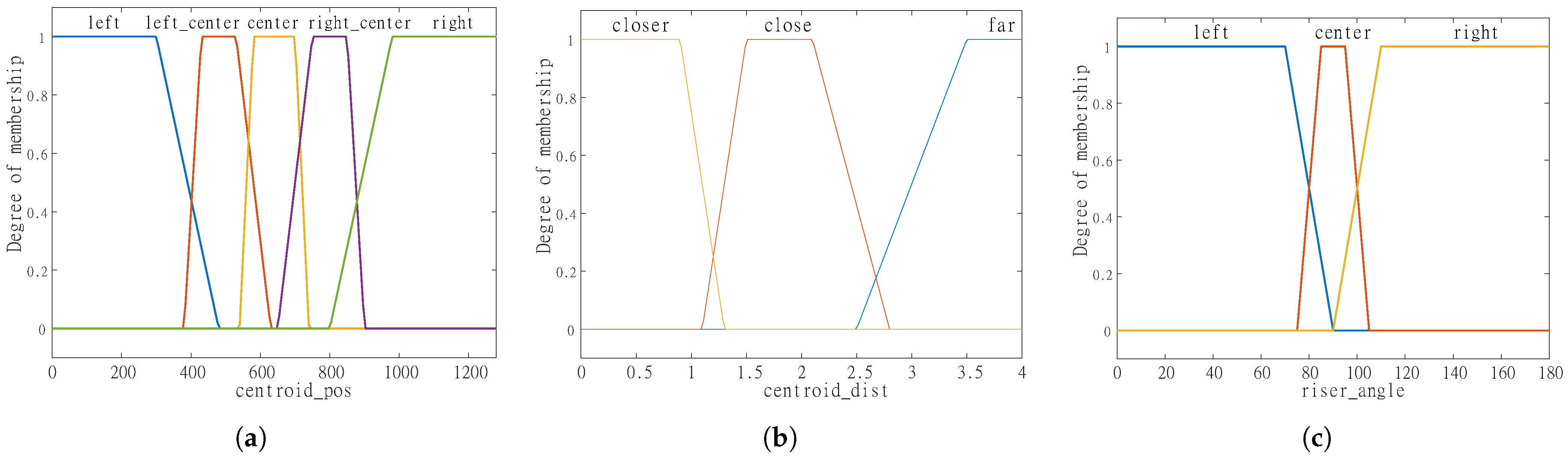
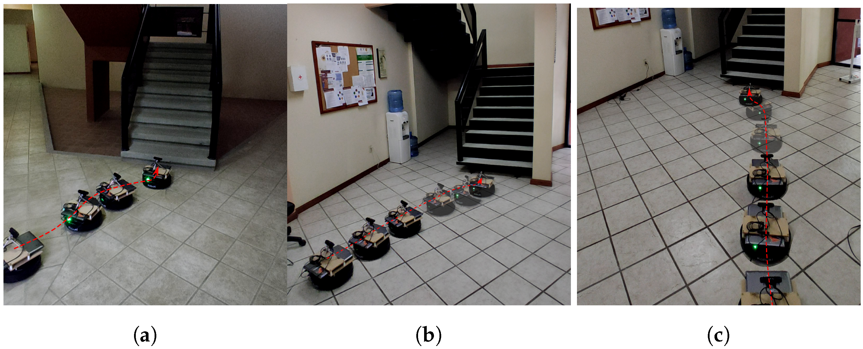
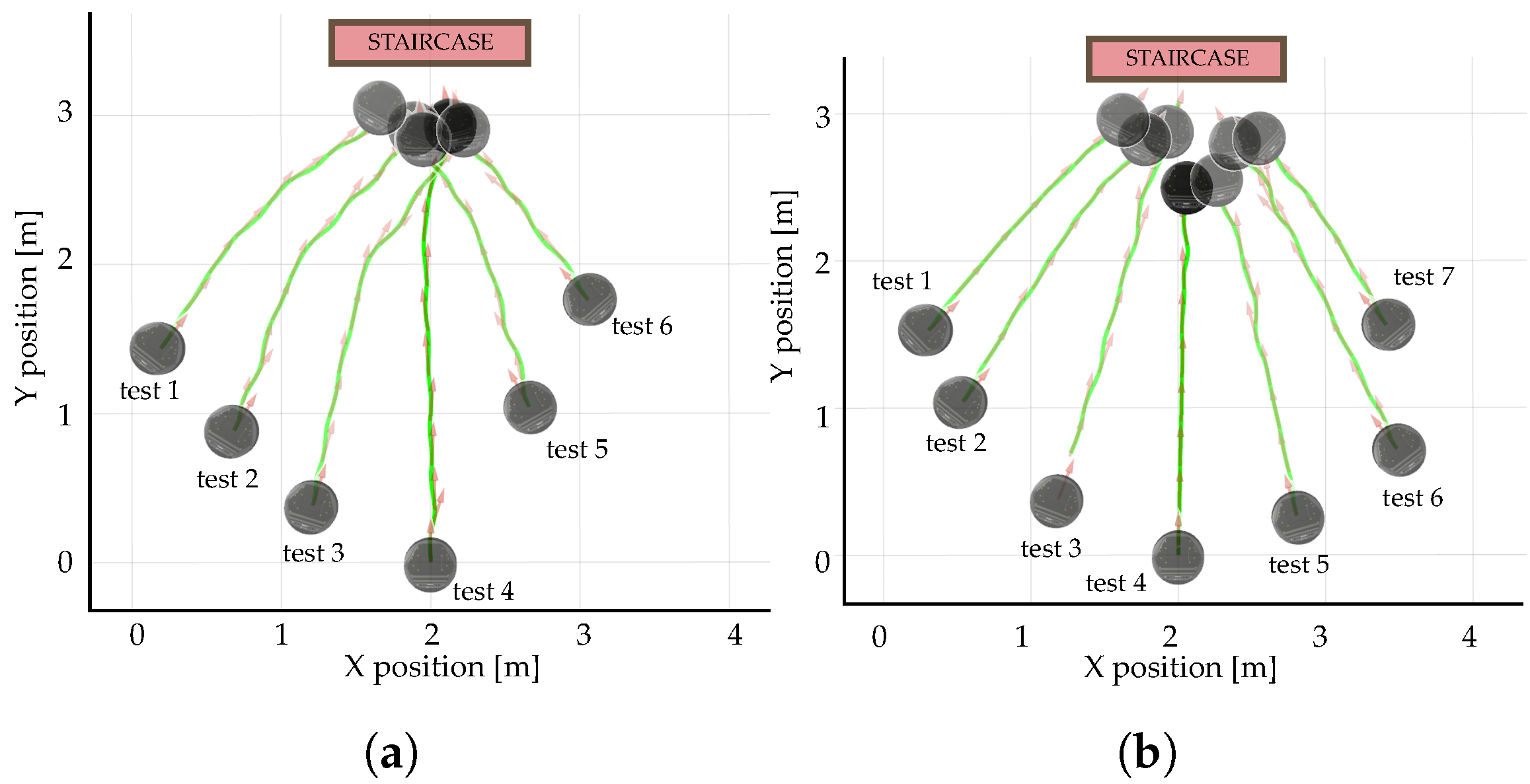
2.4. Fuzzy Controller for Alignment
- Fuzzy variables and fuzzy sets:
- –
- Input variables:
- ∗
- Center of the bounding box with the detected staircase (centroid_pos).
- ·
- Fuzzy sets: left, left_center, center, right_center and right.
- ∗
- Distance to the centroid of the staircase (centroid_dist).
- ·
- Fuzzy sets: closer, close, far.
- ∗
- Staircase orientation (riser_angle).
- ·
- Fuzzy sets: left, center and right.
- –
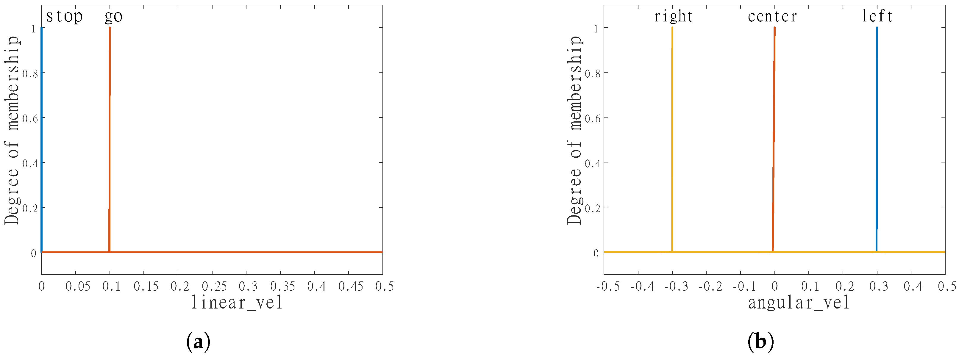
- Output variables:
- ∗
- Linear velocity (linear_vel).
- ·
- Fuzzy sets: stop and go.
- ∗
- Angular velocity (angular_vel).
- ·
- Fuzzy sets: left, center and right.
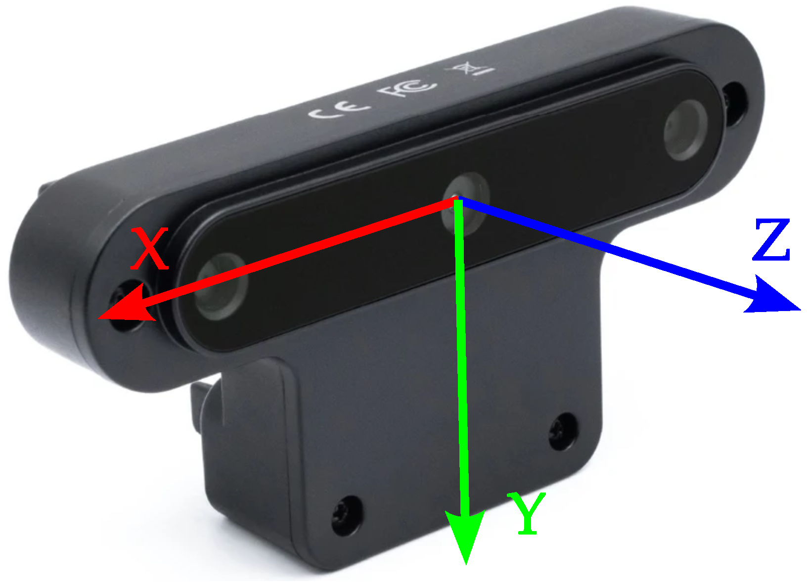
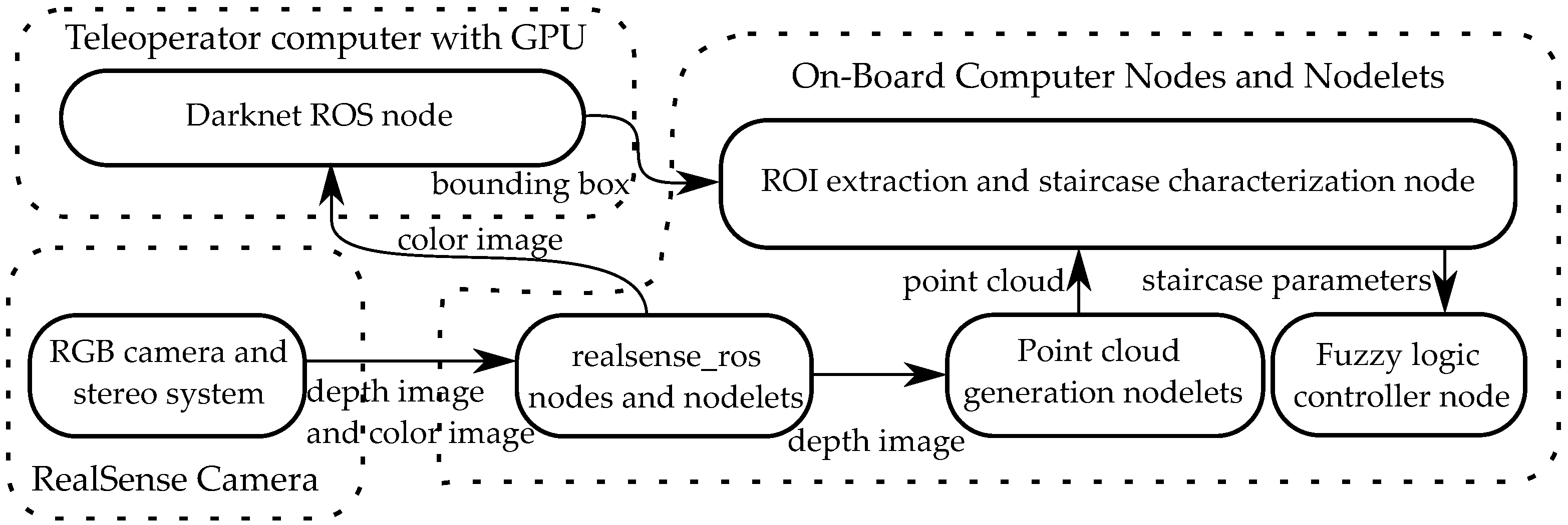
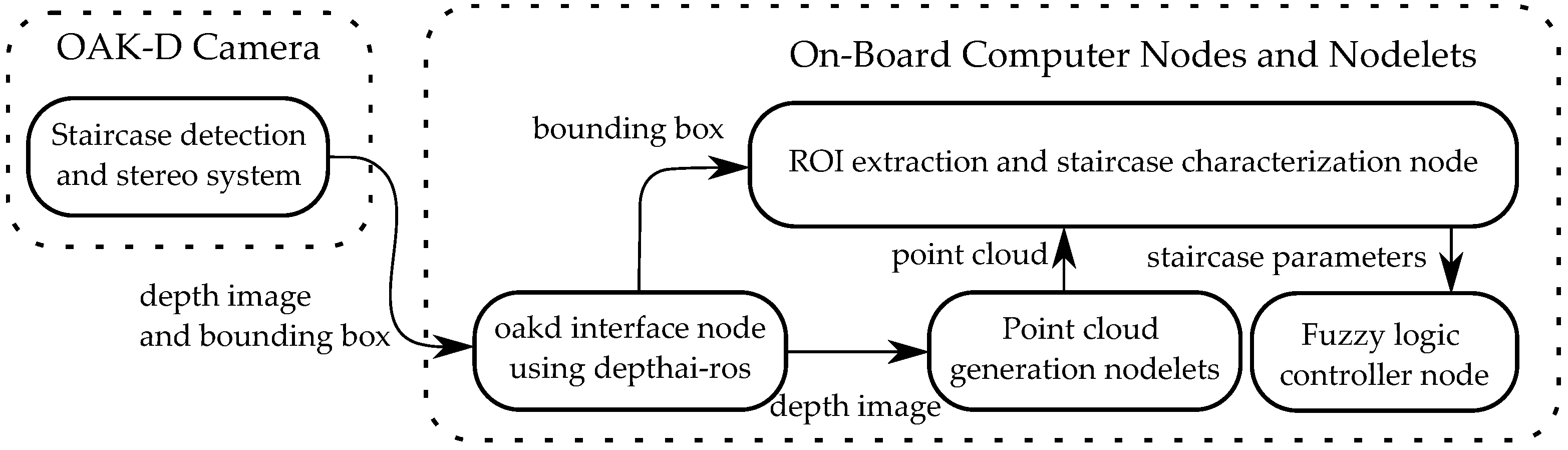
2.5. Description of the Cameras Used
2.6. ROS Pipeline
3. Results
Training of the Detector
- Selecting the appropriate number of iterations and subdivisions of the batch.
- Setting random flag = 1 in config file will increase precision by training YOLO for different resolutions.
- To detect both large and small objects use modified YOLO versions, which include more detection stages (more YOLO layers).
- Use non-labeled images during training.
4. Conclusions
Author Contributions
Funding
Institutional Review Board Statement
Informed Consent Statement
Data Availability Statement
Acknowledgments
Conflicts of Interest
Appendix A

| Rule | IF | THEN | |||
|---|---|---|---|---|---|
| Centroid_pos AND | Centroid_dist AND | Riser_angle | Linear_vel AND | Angular_vel | |
| 1 | left | far | left | go | left |
| 2 | left | far | center | go | left |
| 3 | left | far | right | go | left |
| 4 | left | close | left | go | left |
| 5 | left | close | center | go | left |
| 6 | left | close | right | go | left |
| 7 | left | closer | left | stop | left |
| 8 | left | closer | center | stop | left |
| 9 | left | closer | right | stop | left |
| 10 | left_center | far | left | go | left |
| 11 | left_center | far | center | go | left |
| 12 | left_center | far | right | go | left |
| 13 | left_center | close | left | go | right |
| 14 | left_center | close | center | go | left |
| 15 | left_center | close | right | go | left |
| 16 | left_center | closer | left | stop | left |
| 17 | left_center | closer | center | stop | left |
| 18 | left_center | closer | right | stop | left |
| 19 | center | far | left | go | center |
| 20 | center | far | center | go | center |
| 21 | center | far | right | go | center |
| 22 | center | close | left | go | right |
| 23 | center | close | center | go | center |
| 24 | center | close | right | go | left |
| 25 | center | closer | left | stop | left |
| 26 | center | closer | center | stop | center |
| 27 | center | closer | right | stop | right |
| 28 | right_center | far | left | go | right |
| 29 | right_center | far | center | go | right |
| 30 | right_center | far | right | go | right |
| 31 | right_center | close | left | go | right |
| 32 | right_center | close | center | go | right |
| 33 | right_center | close | right | go | left |
| 34 | right_center | closer | left | stop | right |
| 35 | right_center | closer | center | stop | right |
| 36 | right_center | closer | right | stop | right |
| 37 | right | far | left | go | right |
| 38 | right | far | center | go | right |
| 39 | right | far | right | go | right |
| 40 | right | close | left | go | right |
| 41 | right | close | center | go | right |
| 42 | right | close | right | go | right |
| 43 | right | closer | left | stop | right |
| 44 | right | closer | center | stop | right |
| 45 | right | closer | right | stop | right |
References
- Murphy, R.R. Disaster Robotics; MIT Press: Cambridge, MA, USA, 2014. [Google Scholar]
- Tadokoro, S. Disaster Robotics: Results from the ImPACT Tough Robotics Challenge; Springer: Cham, Switzerland, 2019; Volume 128. [Google Scholar]
- Cong, Y.; Li, X.; Liu, J.; Tang, Y. A stairway detection algorithm based on vision for ugv stair climbing. In Proceedings of the 2008 IEEE International Conference on Networking, Sensing and Control, Sanya, China, 6–8 April 2008; pp. 1806–1811. [Google Scholar]
- Hernández, D.C.; Jo, K.H. Stairway tracking based on automatic target selection using directional filters. In Proceedings of the 2011 17th Korea-Japan Joint Workshop on Frontiers of Computer Vision (FCV), Ulsan, Korea, 9–11 February 2011; pp. 1–6. [Google Scholar]
- Huang, X.; Tang, Z. Staircase Detection Algorithm Based on Projection-Histogram. In Proceedings of the 2018 2nd IEEE Advanced Information Management, Communicates, Electronic and Automation Control Conference (IMCEC), Xi’an, China, 25–27 May 2018; pp. 1130–1133. [Google Scholar]
- Lee, H.W.; Wang, C.; Lu, B.Y. Study on the Computer Vision of the Biped Robot for Stable Walking on the Stairs. In Proceedings of the 2019 IEEE International Conference on Consumer Electronics-Taiwan (ICCE-TW), Yilan, Taiwan, 20–22 May 2019; pp. 1–2. [Google Scholar]
- Zhong, C.; Zhuang, Y.; Wang, W. Stairway detection using Gabor filter and FFPG. In Proceedings of the 2011 International Conference of Soft Computing and Pattern Recognition (SoCPaR), Dalian, China, 14–16 October 2011; pp. 578–582. [Google Scholar]
- Kajabad, E.N.; Begen, P.; Nizomutdinov, B.; Ivanov, S. YOLOv4 for Urban Object Detection: Case of Electronic Inventory in St. In Petersburg. In Proceedings of the 2021 28th Conference of Open Innovations Association (FRUCT), Moscow, Russia, 27–29 January 2021; pp. 316–321. [Google Scholar]
- Patil, U.; Gujarathi, A.; Kulkarni, A.; Jain, A.; Malke, L.; Tekade, R.; Paigwar, K.; Chaturvedi, P. Deep learning based stair detection and statistical image filtering for autonomous stair climbing. In Proceedings of the 2019 Third IEEE International Conference on Robotic Computing (IRC), Naples, Italy, 25–27 February 2019; pp. 159–166. [Google Scholar]
- Ilyas, M.; Lakshmanan, A.K.; Le, A.V.; Mohan, R.E. Staircase recognition and localization using convolution neural network (cnn) for cleaning robot application. Preprints 2018. [Google Scholar] [CrossRef]
- Miyakawa, K.; Kanda, T.; Ohya, J.; Ogata, H.; Hashimoto, K.; Takanishi, A. Automatic estimation of the position and orientation of stairs to be reached and climbed by a disaster response robot by analyzing 2D image and 3D point cloud. Int. J. Mech. Eng. Robot. Res. 2020, 9, 1312–1321. [Google Scholar] [CrossRef]
- Choi, Y.J.; Rahim, T.; Ramatryana, I.N.A.; Shin, S.Y. Improved CNN-Based Path Planning for Stairs Climbing in Autonomous UAV with LiDAR Sensor. In Proceedings of the 2021 International Conference on Electronics, Information, and Communication (ICEIC), Jeju, Korea, 31 January–3 February 2021; pp. 1–7. [Google Scholar]
- Panchi, N.; Agrawal, K.; Patil, U.; Gujarathi, A.; Jain, A.; Namdeo, H.; Chiddarwar, S.S. Deep Learning-Based Stair Segmentation and Behavioral Cloning for Autonomous Stair Climbing. Int. J. Semant. Comput. 2019, 13, 497–512. [Google Scholar] [CrossRef]
- Ciobanu, A.; Morar, A.; Moldoveanu, F.; Petrescu, L.; Ferche, O.; Moldoveanu, A. Real-time indoor staircase detection on mobile devices. In Proceedings of the 2017 21st International Conference on Control Systems and Computer Science (CSCS), Bucharest, Romania, 29–31 May 2017; pp. 287–293. [Google Scholar]
- Sharma, B.; Syed, I.A. Where to begin climbing? Computing start-of-stair position for robotic platforms. In Proceedings of the 2019 11th International Conference on Computational Intelligence and Communication Networks (CICN), Honolulu, HI, USA, 3–4 January 2019; pp. 110–116. [Google Scholar]
- Souto, L.A.; Castro, A.; Gonçalves, L.M.G.; Nascimento, T.P. Stairs and doors recognition as natural landmarks based on clouds of 3D edge-points from RGB-D sensors for mobile robot localization. Sensors 2017, 17, 1824. [Google Scholar] [CrossRef] [PubMed] [Green Version]
- Woo, S.; Shin, J.; Lee, Y.H.; Lee, Y.H.; Lee, H.; Kang, H.; Choi, H.R.; Moon, H. Stair-mapping with point-cloud data and stair-modeling for quadruped robot. In Proceedings of the 2019 16th International Conference on Ubiquitous Robots (UR), Jeju, Korea, 24–27 June 2019; pp. 81–86. [Google Scholar]
- Westfechtel, T.; Ohno, K.; Mertsching, B.; Hamada, R.; Nickchen, D.; Kojima, S.; Tadokoro, S. Robust stairway-detection and localization method for mobile robots using a graph-based model and competing initializations. Int. J. Robot. Res. 2018, 37, 1463–1483. [Google Scholar] [CrossRef]
- Kuznetsova, A.; Rom, H.; Alldrin, N.; Uijlings, J.; Krasin, I.; Pont-Tuset, J.; Kamali, S.; Popov, S.; Malloci, M.; Kolesnikov, A.; et al. The open images dataset v4. Int. J. Comput. Vis. 2020, 128, 1956–1981. [Google Scholar] [CrossRef] [Green Version]
- Bashiri, F.S.; LaRose, E.; Peissig, P.; Tafti, A.P. MCIndoor20000: A fully-labeled image dataset to advance indoor objects detection. Data Brief 2018, 17, 71–75. [Google Scholar] [CrossRef] [PubMed]
- Google. Google Images. Available online: https://www.google.com/imghp?hl=en (accessed on 10 December 2020).
- Tzutalin. LabelImg. Git code. Available online: https://github.com/tzutalin/labelImg (accessed on 7 January 2021).
- Bochkovskiy, A.; Wang, C.Y.; Liao, H.Y.M. Yolov4: Optimal speed and accuracy of object detection. arXiv 2020, arXiv:2004.10934. [Google Scholar]
- Wang, C.Y.; Liao, H.Y.M.; Wu, Y.H.; Chen, P.Y.; Hsieh, J.W.; Yeh, I.H. CSPNet: A new backbone that can enhance learning capability of CNN. In Proceedings of the IEEE/CVF Conference on Computer Vision and Pattern Recognition Workshops, Seattle, WA, USA, 14–19 June 2020; pp. 390–391. [Google Scholar]
- He, K.; Zhang, X.; Ren, S.; Sun, J. Spatial pyramid pooling in deep convolutional networks for visual recognition. IEEE Trans. Pattern Anal. Mach. Intell. 2015, 37, 1904–1916. [Google Scholar] [CrossRef] [Green Version]
- Liu, S.; Qi, L.; Qin, H.; Shi, J.; Jia, J. Path aggregation network for instance segmentation. In Proceedings of the IEEE Conference on Computer Vision and Pattern Recognition, Salt Lake City, UT, USA, 18–23 June 2018; pp. 8759–8768. [Google Scholar]
- Redmon, J.; Farhadi, A. Yolov3: An incremental improvement. arXiv 2018, arXiv:1804.02767. [Google Scholar]
- Rabbani, T.; Van Den Heuvel, F.; Vosselmann, G. Segmentation of point clouds using smoothness constraint. Int. Arch. Photogramm. Remote Sens. Spat. Inf. Sci. 2006, 36, 248–253. [Google Scholar]
- Fischler, M.A.; Bolles, R.C. Random sample consensus: A paradigm for model fitting with applications to image analysis and automated cartography. Commun. ACM 1981, 24, 381–395. [Google Scholar] [CrossRef]
- Grossman, S.I. Álgebra Lineal, 7th ed.; McGraw Hill/Interamericana Editores, S.A. de C.V.: Mexico City, Mexico, 2012. [Google Scholar]
- Luxonis. Depthai-Ros. Git Code. Available online: https://github.com/luxonis/depthai-ros (accessed on 1 August 2021).
- ROS. Depth_img_proc. Package Summary. Available online: http://wiki.ros.org/depth_image_proc (accessed on 17 July 2021).
- Rusu, R.B.; Cousins, S. 3d is here: Point cloud library (pcl). In Proceedings of the 2011 IEEE International Conference on Robotics and Automation, Shanghai, China, 9–13 May 2011; pp. 1–4. [Google Scholar]
- Gazebo. Robot Simulation Made Easy. Available online: http://gazebosim.org/ (accessed on 1 September 2021).
- AlexeyAB. Darknet. Git Code. Available online: https://github.com/AlexeyAB/darknet (accessed on 15 August 2021).


| No. | Total Iterations | Subdivisions | Total Layers | Detection Layers | Random Flag | Negative Images | mAP@0.5 |
|---|---|---|---|---|---|---|---|
| 1 | 2000 | 24 | 38 | 2 | 1 | NO | 59.25% |
| 2 | 2000 | 24 | 127 | 3 | 0 | NO | 76.74% |
| 3 | 4000 | 24 | 31 | 3 | 1 | NO | 45.24% |
| 4 | 4000 | 24 | 38 | 2 | 0 | NO | 66.20% |
| 5 | 2000 | 24 | 38 | 2 | 0 | NO | 63.08% |
| 6 | 4000 | 24 | 38 | 2 | 0 | YES | 65.53% |
| 7 | 10,000 | 8 | 38 | 2 | 0 | YES | 70.93% |
| 8 | 10,000 | 4 | 45 | 3 | 0 | YES | 68.17% |
| 9 | 10,000 | 8 | 45 | 3 | 0 | YES | 65.32% |
| No. | Approximate Training Time [min] | Approximate Inference Time [ms] | Precision | Recall | F1 Score | Avg. IoU | mAP@0.5 |
|---|---|---|---|---|---|---|---|
| 1 | 40 | 5.3 | 0.76 | 0.49 | 0.59 | 55.09% | 59.25% |
| 2 | 186 | 44.1 | 0.80 | 0.69 | 0.74 | 63.62% | 76.74% |
| 3 | 104 | 5.6 | 0.85 | 0.17 | 0.29 | 61.86% | 45.24% |
| 4 | 100 | 5.2 | 0.73 | 0.62 | 0.67 | 52.76 % | 66.20% |
| 5 | 60 | 5.2 | 0.74 | 0.56 | 0.64 | 53.62% | 63.08% |
| 6 | 75 | 5.47 | 0.73 | 0.62 | 0.67 | 54.00 % | 65.53% |
| 7 | 175 | 5.4 | 0.81 | 0.62 | 0.70 | 61.36% | 70.93% |
| 8 | 160 | 6.1 | 0.88 | 0.52 | 0.65 | 67.57 % | 68.17% |
| 9 | 154 | 6.2 | 0.77 | 0.57 | 0.65 | 58.22% | 65.32% |
Publisher’s Note: MDPI stays neutral with regard to jurisdictional claims in published maps and institutional affiliations. |
© 2021 by the authors. Licensee MDPI, Basel, Switzerland. This article is an open access article distributed under the terms and conditions of the Creative Commons Attribution (CC BY) license (https://creativecommons.org/licenses/by/4.0/).
Share and Cite
Sánchez-Rojas, J.A.; Arias-Aguilar, J.A.; Takemura, H.; Petrilli-Barceló, A.E. Staircase Detection, Characterization and Approach Pipeline for Search and Rescue Robots. Appl. Sci. 2021, 11, 10736. https://doi.org/10.3390/app112210736
Sánchez-Rojas JA, Arias-Aguilar JA, Takemura H, Petrilli-Barceló AE. Staircase Detection, Characterization and Approach Pipeline for Search and Rescue Robots. Applied Sciences. 2021; 11(22):10736. https://doi.org/10.3390/app112210736
Chicago/Turabian StyleSánchez-Rojas, José Armando, José Aníbal Arias-Aguilar, Hiroshi Takemura, and Alberto Elías Petrilli-Barceló. 2021. "Staircase Detection, Characterization and Approach Pipeline for Search and Rescue Robots" Applied Sciences 11, no. 22: 10736. https://doi.org/10.3390/app112210736
APA StyleSánchez-Rojas, J. A., Arias-Aguilar, J. A., Takemura, H., & Petrilli-Barceló, A. E. (2021). Staircase Detection, Characterization and Approach Pipeline for Search and Rescue Robots. Applied Sciences, 11(22), 10736. https://doi.org/10.3390/app112210736