Article

Developments of Adapted Clothing for Physically Disabled People with Scoliosis Using 3D Geometrical Model

1
College of Textile and Clothing Engineering, Soochow University, 178 G. J. D. Road, Suzhou 215021, China
2
ENSAIT-GEMTEX Lab., Lille Université, 2 Allée Louise et Victor Champier, 59056 Roubaix, France
3
Ethiopian Institute of Textile and Fashion Technology (EiTEX), Bahir Dar University, Bahir Dar 1037, Ethiopia
*
Authors to whom correspondence should be addressed.
Appl. Sci. 2021, 11(22), 10655; https://doi.org/10.3390/app112210655
Submission received: 3 October 2021 / Revised: 31 October 2021 / Accepted: 1 November 2021 / Published: 12 November 2021
(This article belongs to the Special Issue New Trends in Design Engineering)

Abstract

:

Featured Application

In this current research work, adapted upper bodices clothing in a virtual reality environment for women with scoliosis was developed based on the 3D model of the thorax which helps to easily determine both anthropometric points and morphological curves. Then, a 2D block pattern was then achieved by flattening the 3D patterns through various methods. Different tests considering the evolution of the pathology were also carried out to predict the different styles of clothes. Additionally, the results of the tests also validated our Geometric model of the garment with 3D ease allowances. The proposed methods could benefit the designer, researchers, and manufacturer working in the field of clothing design for physically disables peoples (and, more specifically, for those with scoliosis).

Abstract

Scoliosis is a deformity of the spine that causes disorders of the rib cage. This makes it difficult to design clothes for affected people without following the shape of the rib cage. This paper presents a new 3D clothing design method based on virtual reality for women with physical disabilities such as scoliosis. The current design method is a variation of the draping techniques commonly used by fashion designers to design clothes on a mannequin or human body. However, the current design process highly considers the skeleton and body scan of the person. The skeleton is used to detect the anthropometric points of the patient, while the body scan allows us to detect the morphological contours at the onset of scoliosis. Thus, both allow us to accurately track the patient’s morphology and atypical shape. The position of the morphological contours is indicated by reference marks that are closely associated with the skeleton. This helps to automatically adapt the garment to the evolution of the patient’s pathology over time. The process of creating the 3D garment was processed based on the 3D model of the thorax, which helps to easily determine the anthropometric points and the morphological curves. Using this data, the geometrical model of the garment could be created with 3D ease allowances. The 2D block pattern was then obtained by flattening the 3D patterns using flattening methods. Finally, various tests were performed considering the evolution of pathology to predict the future garment. These tests validate our geometrical model of the garment with 3D ease allowances by comparing the results with previous work.

1. Introduction

The adaptive garment is specifically designed to accommodate the special requirements of people with disabilities and special needs to overcome the challenges associated with self-dressing, health problems, ergonomics comfort, fit, style, fashion etc. For the past few decades, the personalization of clothing for people with disabilities has been a successful business model for many fashion brands [1]. Concepts such as tailor-made design for the customer are also gaining importance and leading to personalized consumer profiles [2,3]. The consumer is supported by a vast set of tools and techniques, which would enable it to be part of the panel of experts with his own experience [4]. In practice, most well-known fashion brands offer some form of mass customization for adapting clothing. However, the majority of solutions only concern the modularity of the products [5]. This means that the individual customer can create their garment using a co-design process from the spectrum of products and variations of given modules. Such tailor-made design for the customer is gaining importance, leading to personalized consumer profiles (which are quite understandable and attractive from a personalizing and marketing point of view). However, it should be noted that the more significant problem of tailoring clothing to the customer’s sizes and shapes has not been resolved. Besides, the traditional pattern-making process is very time-consuming and requires professional fashion design knowledge. To develop a fitting, functional and comfortable garment to meet a specific customer’s individual needs, pattern makers must rely on a “trial and error” procedure [3]. Previous research work has involved and puts a great effort into finding out an optimum clothing design solution to the special demands of an individual through the application of new technologies [6,7]. For example, some researchers have developed custom and special occasion dresses for women that have spina bifida or osteogenesis imperfecta which is a common physical characteristic of severe spinal curvature, resulting in extreme body asymmetry, which requires the use of forearm crutches and waist-to-foot braces for upright mobility [8].
Modelling the 3D garment on the virtual body becomes one of the critical techniques required to implement the designing of not only technical products [9,10] but also functional garments for disabled people [11]. For example, some research work proposed 3D modelling in relation to the virtual fitting by setting up a 3D wireframe model of the garment connected to the wearer by its morphological contours and anthropometric points [1,12]. Another study works on the new design method and virtual prototyping of garments using CASP (curvature, acceleration, symmetry, proportionality) for people with scoliosis peoples taking into account the deformed areas of the body [13]. In general, the design of the garment is carried out directly on a mannequin or wooden mannequin with many precise and repetitive adjustments [14]. This step, commonly known as the draping technique, requires expert manual know-how [15]. Other design methods such as 2D model creation methods are also widely used as they are highly practiced today in a digital environment. Both designing systems not only reduce the time of the design stage following an increasing demand [11] but also represent a possible solution which is cost-effective if implemented in a 3D environment [16,17]. Besides, for the last few decades, adaptive clothing was designed based on a digitized human body by characterizing each body part including the chest, shoulders, scapula, neck, back, hips, lateral parts, etc. However, such designing methods of a sophisticated 3D virtual garment model for a 3D virtual human model are still labor-intensive since most existing garment models are custom-made for a specific human model and cannot be easily reused for other individuals [18].
To solve such problems, we propose a new 3D garment creation process based on virtual reality for people with physical disabilities such as scoliosis. Such a designing method can be considered as a variation of the draping techniques mostly used by designers of fashion houses who create directly on a mannequin or human body. The first specificity of this process is that it is directly connected to the skeleton [19] and the body scan of the person. This makes it possible to follow the patient’s morphology and to consider their atypical shape. The skeleton thus makes it possible to detect the anthropometric points of the patient whereas, the body scan helps to capture the morphological contours at the start of scoliosis. The position of the morphological contours is given by reference marks connected to the skeleton so that the garment could automatically adapt to the evolution of the patient’s pathology over time.

2. The Traditional Design Process of Clothing

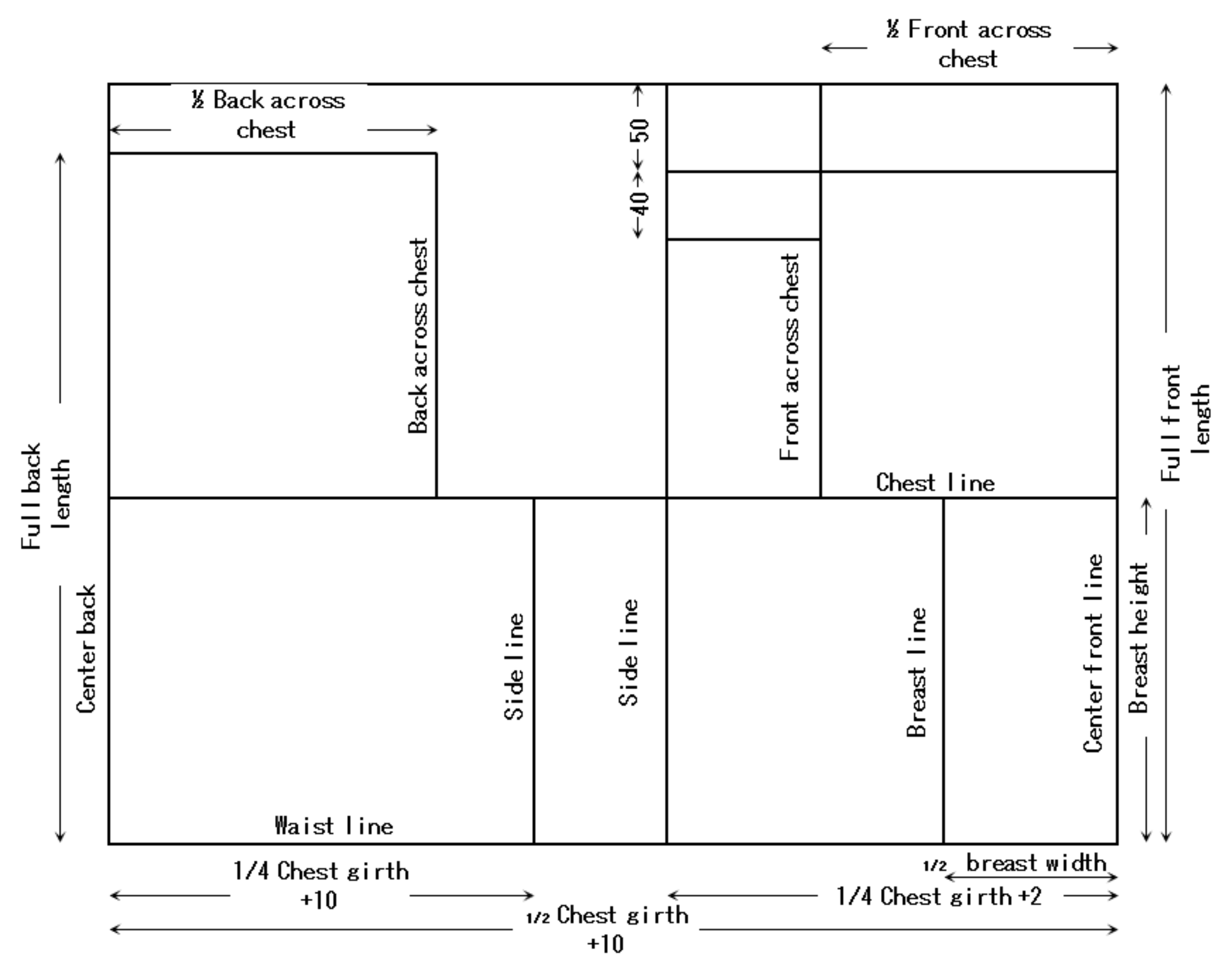
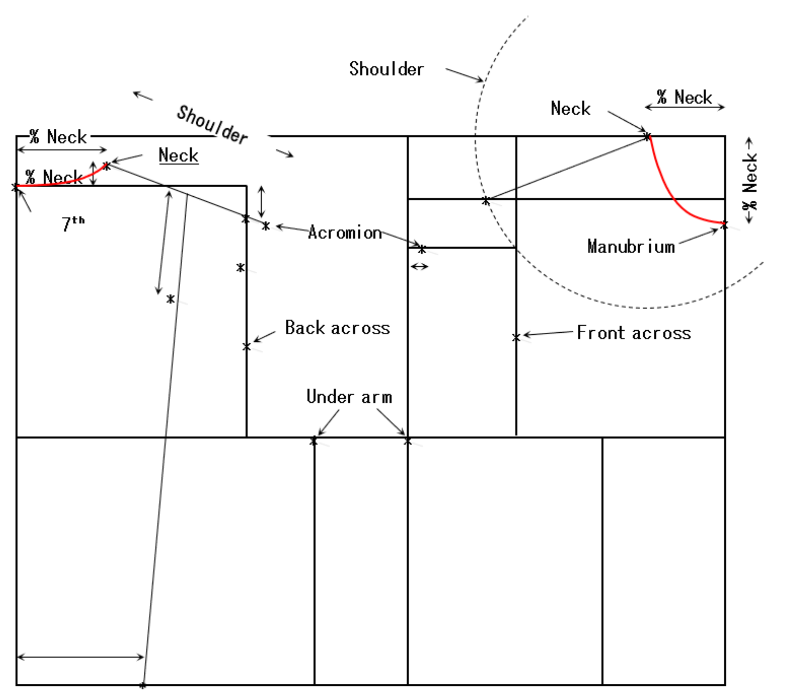
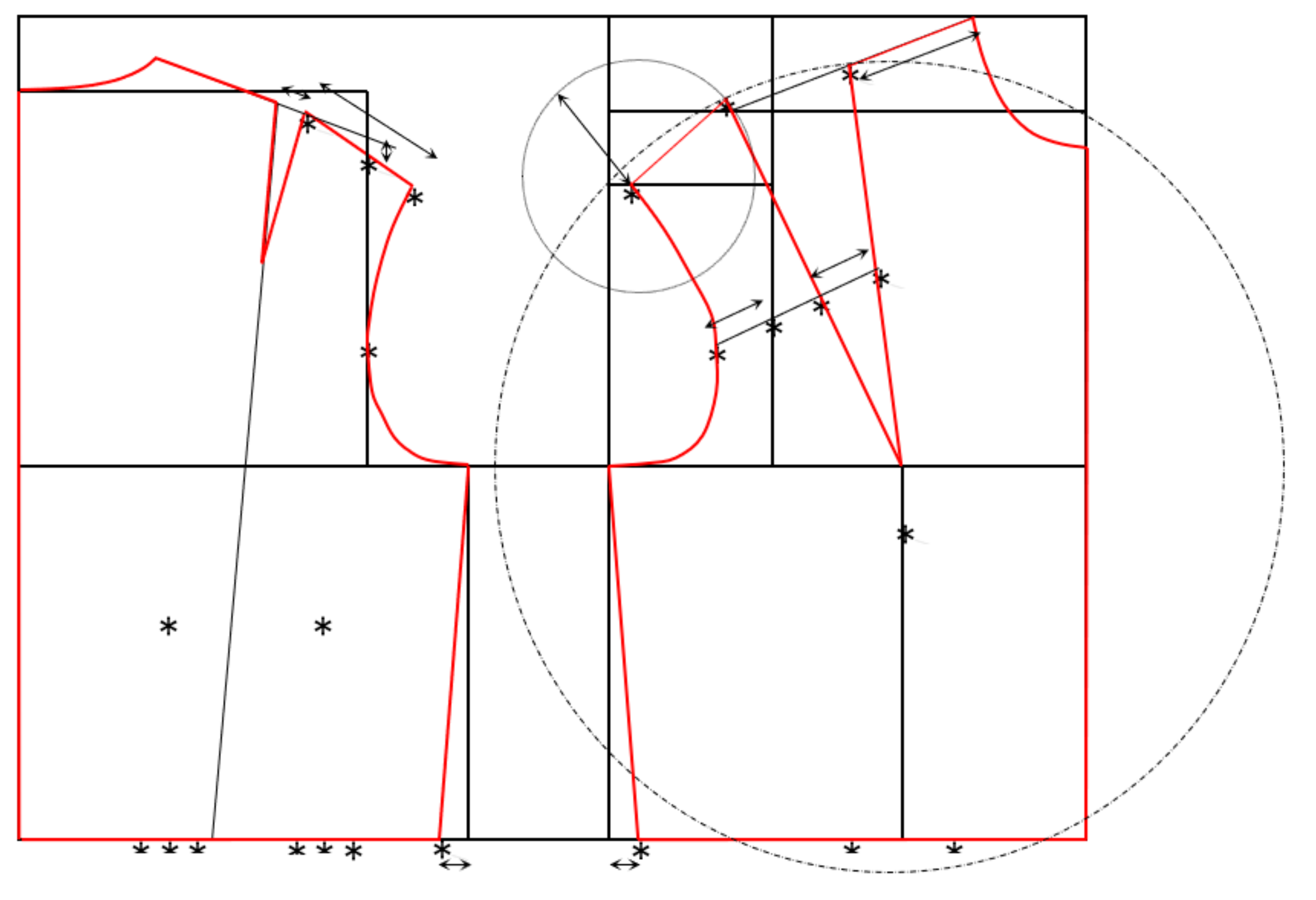
2.1. 2D Block Pattern Creation Process

There are various methods of flat cutting to obtain womens’ block pattern. However, these methods can be different and mostly depend on the country or the designers who developed the method. Besides, even within the same country, there is a possibility of having different methods depending on the fashion school and the teachers. Despite this diversity of design techniques, which depend on the perception of pattern, the transition from 3D to 2D is generally referred to as flattening. However, the results of the different technique remain relatively close; all of the techniques follow a common strategy which involves draping a canvas over the women’s body as close as possible. These methods usually start from a basic rectangle whose horizontal direction represents the greatest morphological contour of the body and whose vertical direction represents the greatest height, as shown in Figure 1 (full anterior length is ½ chest circumference +10).
Such a rectangle is often reduced to two perpendicular lines representing one of the corners of the rectangle, with the same aim of making the patterns according to the measurements of the people. Then, different lines parallel to the bottom horizontal line of the rectangle (Figure 1; waistline) are created. This line makes it possible to position the different morphological contours (chest, breast height, full back length, shoulder slopes by values from 50 to 40) concerning each other in the vertical direction as shown in Figure 1. A similar process is performed vertically for the right and left vertical lines of the rectangle (center front and back lines) to define the other morphological lines (back over chest, front over chest, breast, side). This step separates the front and the back. However, morphological contours alone are not sufficient to create a pattern. The human skeleton, however, does tell us about the anthropometry of the body and its morphology.
Some anthropometric points, such as the acromion, the seventh cervical, the manubrium, the front over the chest, the back over the chest, the axilla, and the side of the neck, as shown in Figure 2 (star points), provide spatial landmarks to create other lines or complementary curves, including the shoulder lines and the neckline, and set the boundaries necessary for the outline of the block pattern. To do this, it is enough to draw the front and rear contours of the block pattern as shown in Figure 3 (line with red color) from the lines characterizing the morphology, passing through the anthropometric points, and integrating the clamps, which allow the flattening of the 3D pattern towards 2D. These darts are located at the chest, shoulder, and waist.

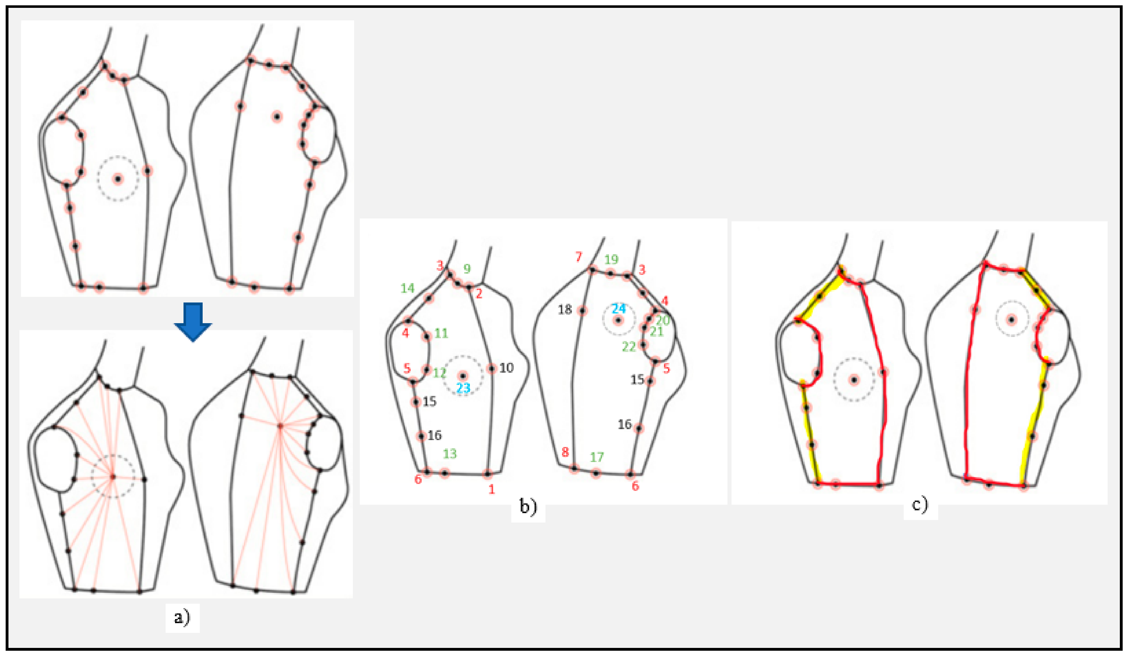
2.2. The Similarity between the 3D and 2D Block Pattern Process

The 3D creation process of the women’s block pattern should follow the design logic of the 2D process. In a first step, this process should identify the morphological contours, locate the anthropometric points, and define each garment’s pattern passing through these strategic points. When creating the 3D pattern on a mannequin, there are some design constraints that must be considered when assembling the product in real or virtual form. These constraints located at the anthropometric point underarm are respected for the tangency of the armhole curves on the contour of the chest, a harmonious continuity of these curves between the front and the back. These constraints are not always sufficiently expressed in the 2D pattern making methods. The difference between 2D and 3D pattern-making methods is that a 2D morphological line represents a 3D morphological contour and the 2D anthropometric point lies in a 3D space. However, one of the biggest differences between the two is the method used to define the 3D ease allowance of the garment. For example, in the case of the 2D creation process, it’s enough to add a value of ease allowance on each contour or line measured on the body. On the other hand, the 3D creation process is much more precise, as the ease allowance is to be spatially controlled by 3D ease allowance zones distributed over the body. Then, it is possible to manage the position, distribution, and balance of the designed garment relative to the wearer’s body and consider morphological deformations. Moreover, the 3D creation process also leads to the personalization of the garment. In contrast, in a 2D process, these ideas are considered when trying on the garment and require multiple real or virtual fittings. Their upstream integration into the 3D creation process drastically shortens the product creation and validation cycle. Besides, in the 3D creation process, it is imperative to anticipate the fall of the garment based on traditional methods of draping on a real body. For this, the contact and non-contact areas must be managed by 3D ease allowance by imagining that the fabric is stretched in some areas, or the fabric follows a draping motion in other areas.

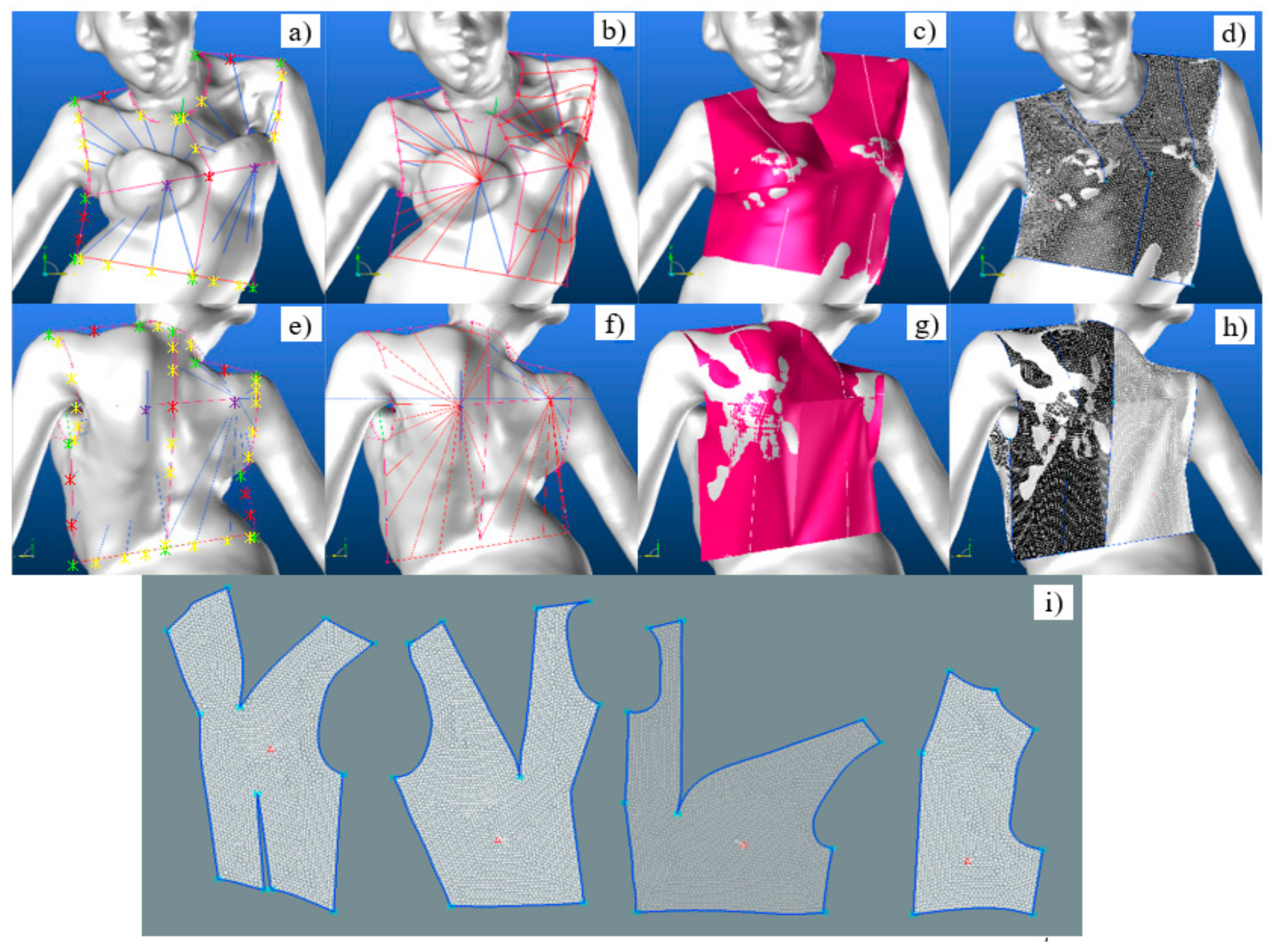
3. 3D Block Pattern Creation Process

The 3D garment creation process is based on a 3D geometric model developed from the conical principle [20] and the improved version for the development of a product adjusted to the morphology of a person with severe scoliosis [21,22]. The women’s block pattern from the conical principle is represented by several triangular planes for the front and the back. The chest and scapulae define the four salient points of the bust as shown in Figure 4a. These represents the common starting points of each triangle for each pattern. The other two ends of the triangles are on the outline of the respective pattern. The outlines in 2D pattern generation are defined by lines with yellow color and curves with blue lines, as shown in Figure 4c. It is created spatially and connected by their ends to the different anthropometric points of the bust as shown in Figure 4b with red color numbering. Other points in the Figure 4b with purple color numbering are strategically located on these lines and curves to improve the monitoring of the body morphology. Basically, they are designed to increase the number of triangles results in a more precise 3D surface mesh of the block pattern.
Later a direct connection by straight lines between the four salient points and the contour points leads to flat triangles. This resulted in a very pronounced collision between the surface of the women’s block pattern and the surface of the body. To avoid such collisions, the lines were then composed of a straight line at the beginning of the contour points. They were extended by curves tangential to the zones around the salient points, which were assimilated in the form of spherical calottes. Another research work also incorporates ease at the salient points, as shown in Figure 5 [17].
In the case of a person with pronounced scoliosis, tests were performed with the 3D geometric model, strictly following the creation strategy, which amounts to the following:
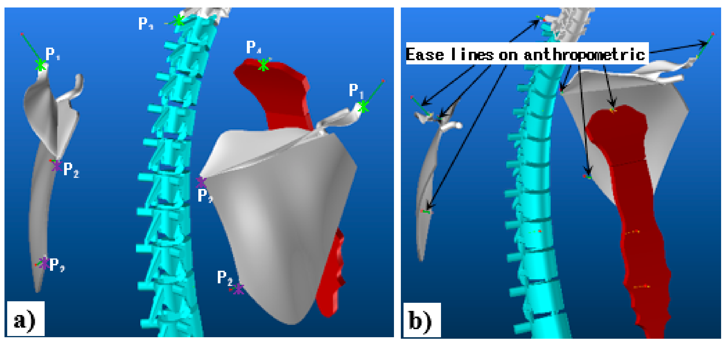
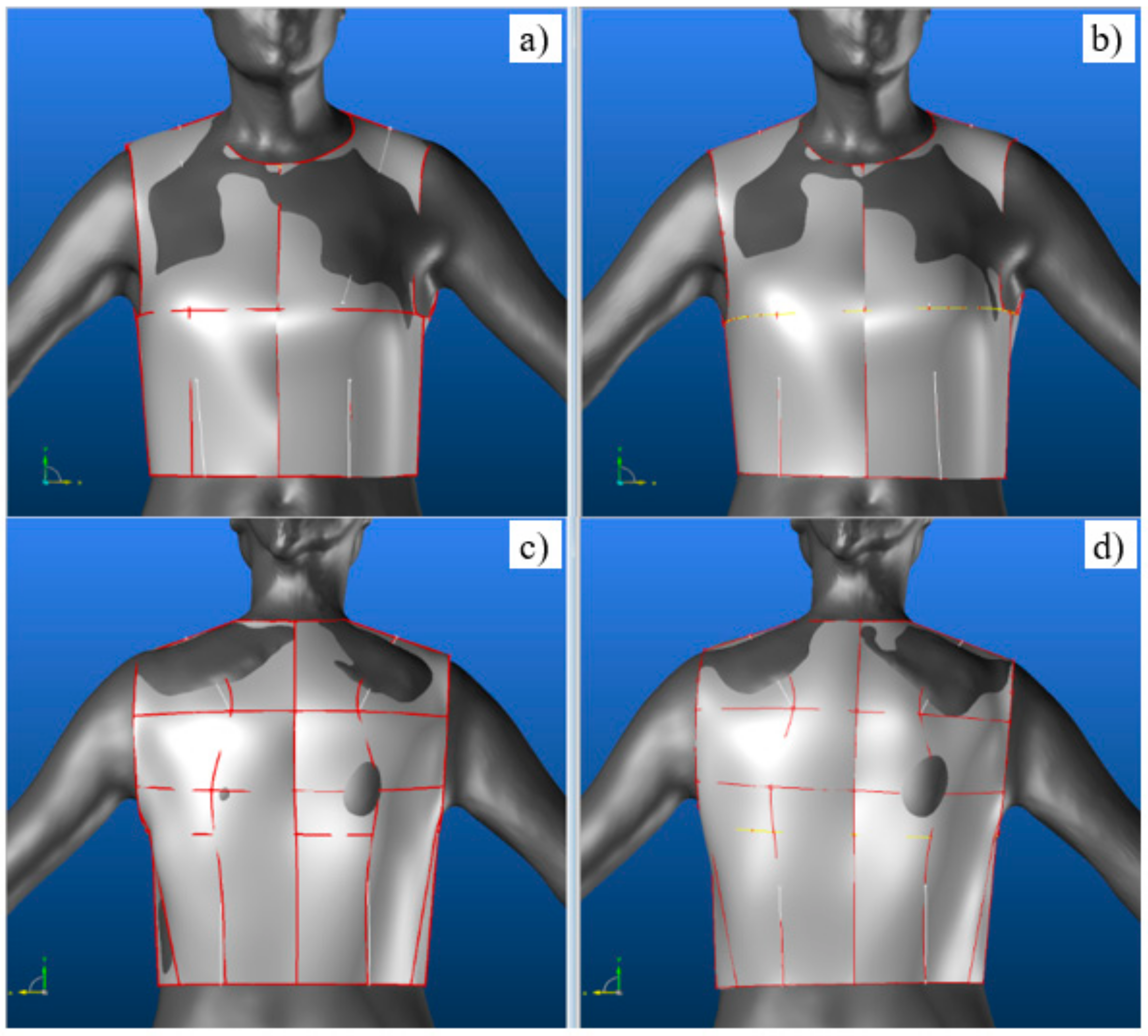
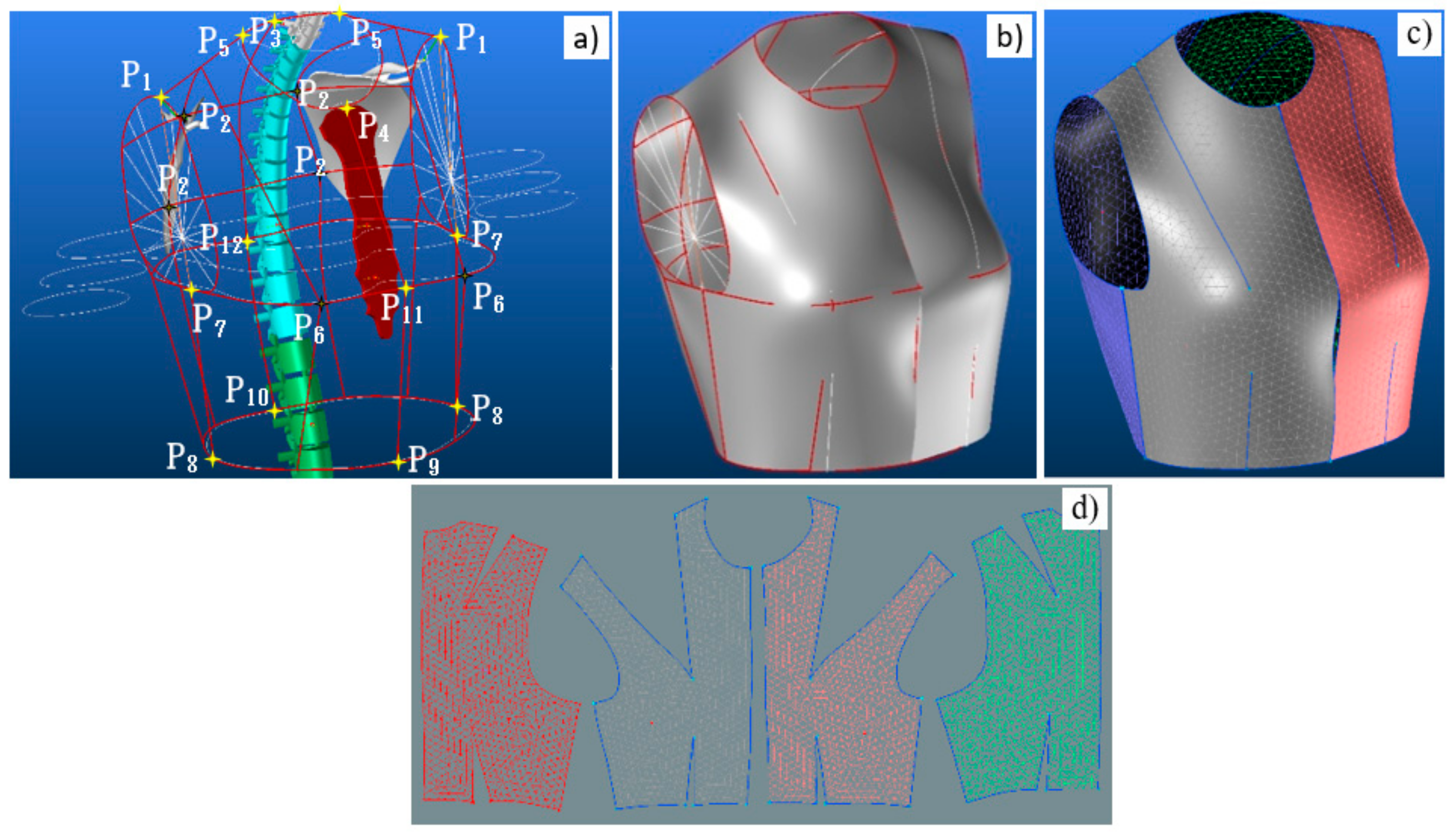
  • Detection of anthropometric points (green star points) and adjustment of ease allowance at each anthropometric point (Figure 6a,e);
  • Detection of protruding (purple star points) and hollow parts of the body (Figure 6a,e);
  • The establishment of the limits of the garment block pattern (red lines and curves) by connecting the anthropometric points (shoulder lines, sidelines, armhole curves, the curve of the middle front, the curve of the middle back) (Figure 6a,e);
  • The positioning of strategic points on the lines and contours (red star points) defining the limits of the garment block pattern (Figure 6a,e);
  • The establishment of distribution points (red star points) between the protruding points of the chest and scapula, between the anthropometric points of the shoulder line and the sideline (Figure 6a,e);
  • The creation of straight lines (blue lines) between the salient points and the contour points of the garment block pattern (Figure 6a,e);
  • The creation of straight/curved lines (curved red lines) between the salient points and the contour points of the garment block pattern (Figure 6b,f);
  • The creation of the surfaces (red surfaces) of each pattern of the block pattern (Figure 6c,g) on which are drawn the lines defining the location of each of the flattening clamps of each pattern (Figure 6c,g);
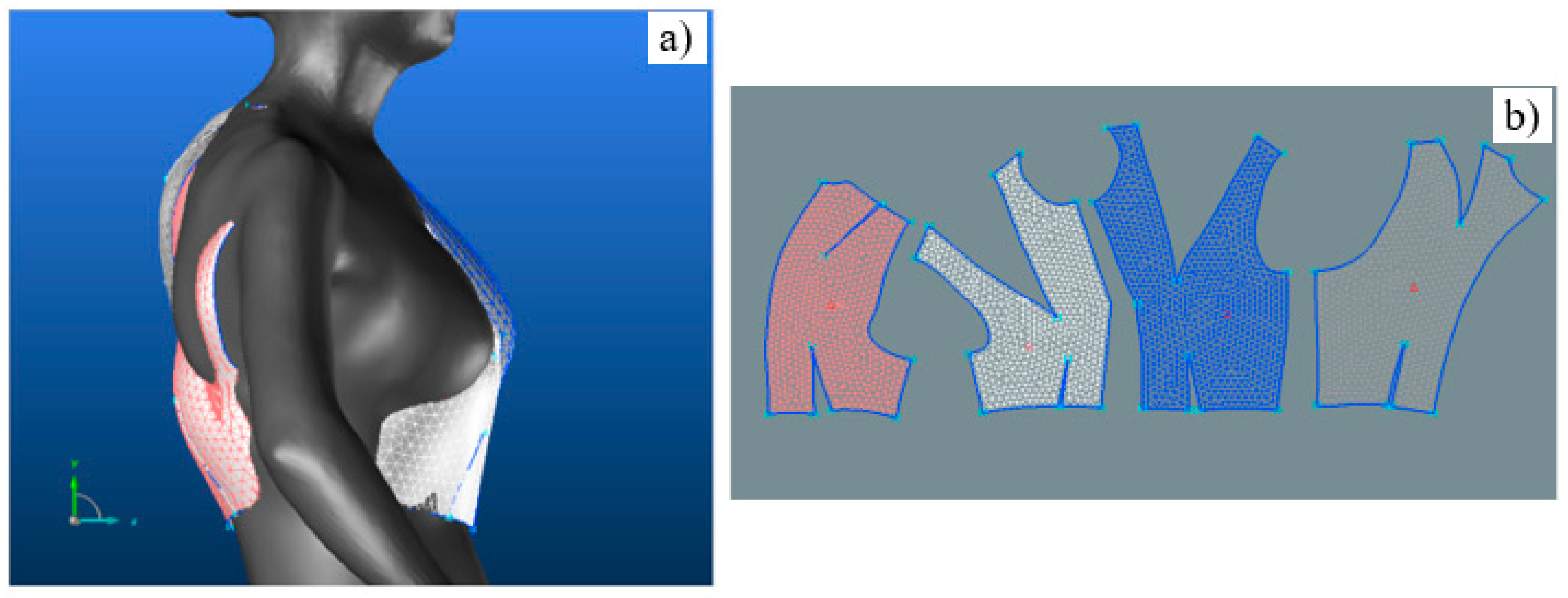
  • The triangular mesh of the surfaces of each pattern of the garment block pattern (Figure 6d,h);
  • The 3D-2D flattening of the meshed surfaces to obtain the four basic block patterns (Figure 6i).

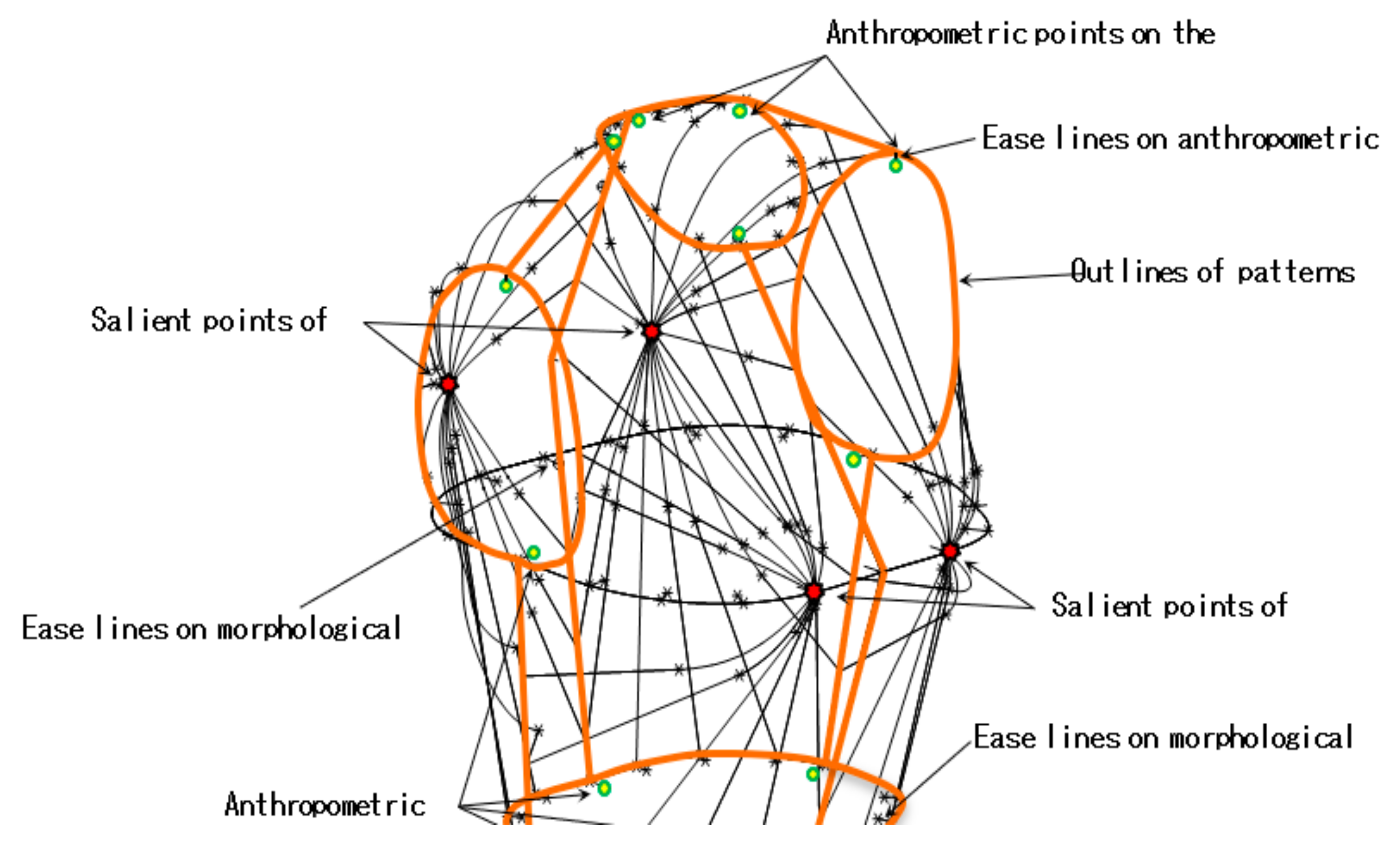
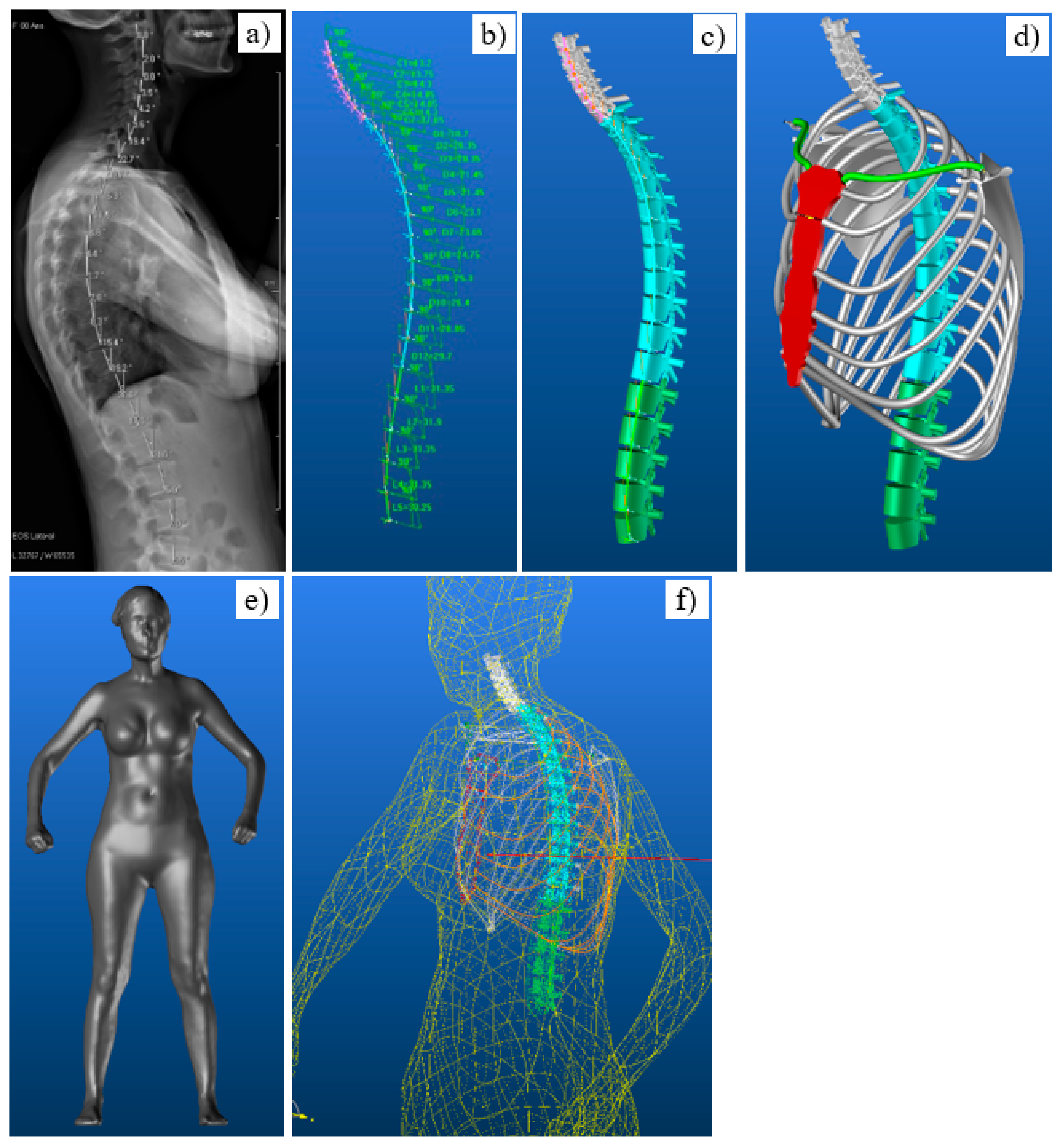
4. 3D Creation Process Connected with the Skeleton

The 3D creation process is interesting due to it leads to a perfect garment fit for the body. It directly relates to the anthropometric data and the morphological contours. Such a method could be also applied to atypical morphologies such as those of scoliosis or another kind of spinal disability. However, certain drawbacks appear despite all of these tailor-made advantages. For example, the detection of anthropometric points and morphological contours is carried out manually and depends on the developer’s finesse. The other concern would be that once the 3D geometric model is created, it can also no longer evolve according to the evolution of the pathology. Scoliosis is a permanent and progressive deviation of the spine. It then leads to a progressive deformation of the thorax and to a particular stage of the disease, namely gibbosity. Therefore, such parameters and specifications should be considered when using the new method to create the 3D block pattern. Therefore, the new 3D geometric model must be associated with the skeleton of the patient with scoliosis, as it fully controls the deformation of the patient’s chest. Thus, the position of the anthropometric points is given by the bones of the skeleton. The morphological contours are created by cross-sections of the scanned surface of the patient’s body. These contours are of course also determined by the skeleton (vertebrae, sternum). The new 3D geometric model must also consider the ease allowance of the garment. Figure 7 shows the structure of this model using the previous model’s strategy with the 3D ease allowance defined by lines of ease distributed at the waist, the chest relative to the morphological contours. The 3D ease allowance is also defined on the different anthropometric points as shown in Figure 7 with green points. For salient points, the straight lines follow the same strategy.

4.1. 3D Model of the Thorax

As shown previously, the 3D creation process must relate to the skeleton of the thorax. In our previous work, we have successfully developed an adaptive 3D thorax model, configured to adapt to any patient morphology with scoliosis [23]. In this work, the pathology develops after a progressive deviation of the spine, adapts to the developing deformity of the spine as well as the angular positions of each of them under different planes, as shown in Figure 8b. The dimensional parameters of the vertebrae are then the height and volume of the thorax. Angular positions manage the deviation of the spine. The 3D model of each vertebra as shown in Figure 8c is connected to the 3D spatial path of the spine (Figure 8b). The 3D thorax model is then connected to each vertebra via the 3D models of the ribs as shown in Figure 8d. In parallel, a 3D scan of the patient as shown in Figure 8e makes it possible to obtain a 3D surface representation of the patient. The complete 3D model of the thorax has been positioned as shown in Figure 8f. The D5 vertebra allows the 3D thorax model to be positioned with precision in the patient’s scan. At this stage, we have the 3D skeleton of the patient integrated into the patient body scan and adapted to the patient’s morphology at a precise moment of his pathology.
Therefore, the current study will use this skeleton to identify the anthropometric points and the morphological contours of the patient and create a garment adapted to this atypical morphology. This garment can then automatically adapt to the deformation of the thorax caused by the spinal deviation.

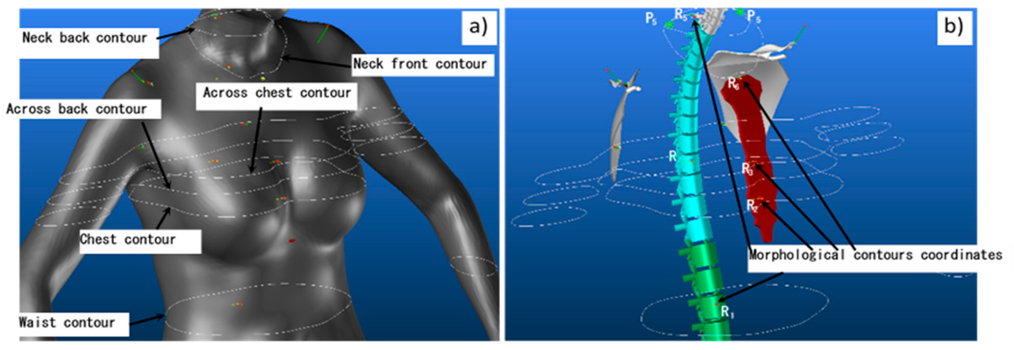
4.2. Detection of Anthropometric Points and Morphological Curves on the Skeleton

The 3D Geometric model of a garment with 3D ease allowances starts with detecting anthropometric points on the skeleton of the 3D thorax model. Here, as shown in Figure 9a, there are three points to detect for each scapula. The first point is for the acromion (P1), the second is for the salient points (P2), and finally the third point is at the end of the seventh cervical (P3). Besides, there is also an additional one point (P4) on the upper/middle part of the manubrium (jugular notch between the two clavicular facets) as shown in Figure 9a. Those different marks are placed on the anthropometric points to create the ease allowance of each point as shown in Figure 9b by the green lines.
The next step is to detect the morphological contours as shown in Figure 10a. For this, the different cut marks were created to get the necessary cross-sections of the scanned body. For example, the first mark, R1, was placed in the middle of the lumbar vertebra L3 which greatly helps to make it possible for defining the contour of the waist. The second mark, R2, was placed on the sternum to provide the chest contour. Its position is relative to a reference R6 located on the anthropometric point P4 as shown in Figure 10b. The contour of the neckline is represented by the two 3D curves which are composed of the front neckline and the back neckline defined in different planes. Another mark, R6, is designed to cut the body at the front neckline, extending the flat area above the chest. Besides, the neckline of the back uses an oriented R5 mark located on the anthropometric point P3 as shown in Figure 10b. The two new anthropometric points, P5, can be then created at the intersection of the front and back necklines. Finally, it is also still very necessary to define the two middle curves of the front and the back. A reference R3 is defined as the reference R2. This mark makes it possible to cut the body at the level of the middle part of the front. The middle of the back is obtained from the mark R7 located in the middle of the dorsal D9.

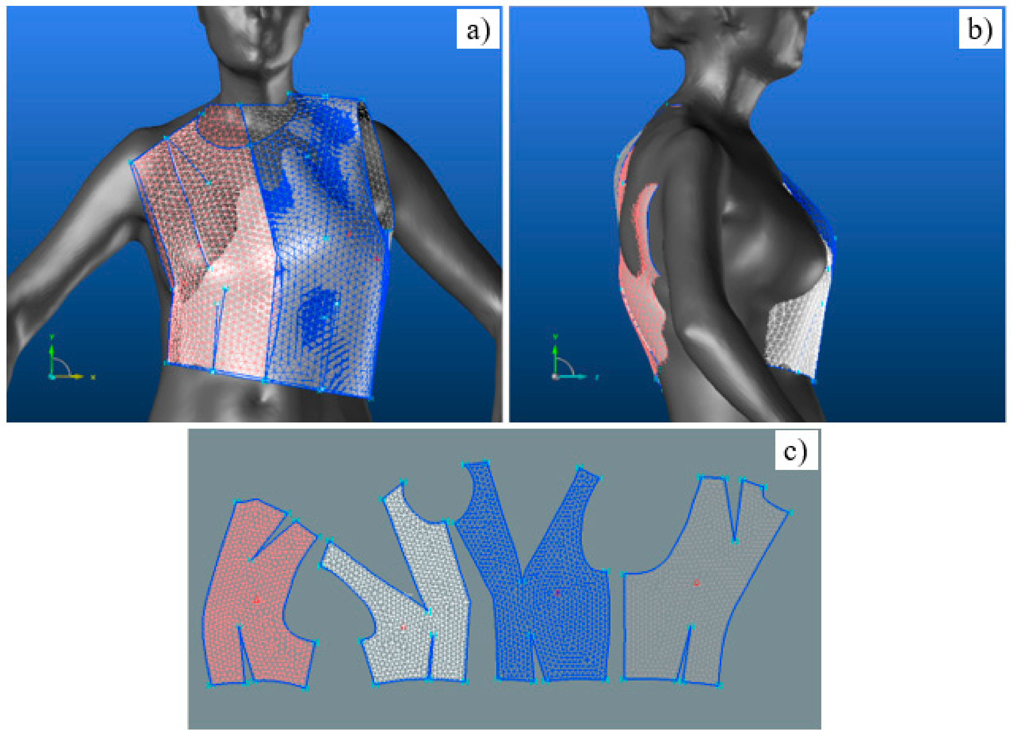
4.3. Developing 3D Model of Adapting Garment

With the recognition of the anthropometric points and the morphological curves that we have marked in the above section, it is now possible to develop the various lines and curves that define the curve mesh of the garment geometric model with 3D ease allowances. The contour of the neck is a 3D curve passing through the end of the ease lines of points P3, P5, P4, and P5 as shown in Figure 11a. The shoulder lines are between P5 and the end of the point lines P1 as shown in Figure 11a. The different morphological contours have been shifted outwards to consider the garment 3D ease allowance. Whereas the two points P7 are then defined on the new chest contour to represent the armpit points as shown in Figure 11a. Likewise, on the new size contour are defined two points (P8 and P7) to create the two sidelines as illustrated in Figure 11a. P7 and P8 result from the intersection between a distribution plan defining the proportion of the pattern of the front to the back and the morphological contours of the chest and the waist [reference plan distribution]. In the same spirit, P9, P11, P10, and P12 are also the result of the intersection between a plane of symmetry and these exact contours (Figure 11a). Of course, these plans are still possible before the deformation of the spine. However, they are then adjusted according to the deformation. For example, P4, P11, and P9 must follow the middle front while P3, P12, and P10 are supposed to fall on the middle back, the spine as shown in Figure 11a. The armholes are positioned relative to points P1 and P7. If one considers only one side, a straight line joins the points P1 and P7, which is defined as a center of distribution of the contour points of the armhole (Figure 11a). This center point is located at the intersection between P1 and P7, and the front middle plane is shown in Figure 10 in reference R3. However, since the armhole on the front is not in the same plane as the armhole on the back, it was necessary to define two design marks in P7 that rotate around an axis represented by the lines P1 and P7. The orientation of the benchmarks is conditioned by the position of the front and back shoulders. Different lines are created on each plane, starting from a central point of a certain length. This helps to define one of the contour points of the armhole of the front or back according to the marking. Later, the angular distribution of these lines allows the positioning of all necessary points to create the half contours of the armholes on the front and back. The protruding points P6 of the front are detected on the new chest contour to create the straight lines joining the contour points of the block pattern at the level of the middle of the shoulder and the waist contour (Figure 11a). The protruding points P2 on the back are used to create the curves joining the contour points of the block pattern at the level of the middle of the shoulder and the waist contour.
The different network of curves and lines as shown in Figure 11b with red color allows to develop and limit the four surfaces of the women’s block pattern a shown in Figure 11b. Later, these surfaces have meshed as shown in Figure 11c by integrating flattening pliers (Figure 11c with blue lines). Finally, the 3D block patterns surface were flattened into 2D block patterns with a flattening process. The flattening result of the four patterns is presented in Figure 11d.

5. Results and Discussion

The geometric model of the garment with 3D ease allowances was first tested on morphology with low scoliosis as shown in Figure 8. Figure 12 shows that the basic bodice correctly follows the morphology if the dimensional parameters of the patient from the EOS scan are applied to it. Since we did not use the spine deformation angles for the first phase, it was found that a slight displacement at the end of the shoulders was caused by the asymmetrical posture of the patient, as shown in Figure 12a,c. After applying the different spinal deformation angles, the geometric model of the garment corrected the defect in the shoulders as shown in Figure 12b. There are also other corrections to the mid-back and mid-front courses that are no longer considered linear. The middle back of the garment perfectly follows the spine.
In the case of a more pronounced development of the spine, as in the patient in Figure 6, it would be sufficient to apply only the angles of deformation of the patient’s spine. Figure 13a,b gives a possible example of the evolution of the patient’s basic bodice with a deformity of the spine evolving towards the patient with a strong deformation. This prediction makes it possible to compare the results of the flattening of such deformation (Figure 13c) with that directly obtained with high scoliosis patient as shown in Figure 6i. In this case, the results from the 2D and 3D of the basic bodice are similar that allows us to validate our geometric model of the adapted garment with 3D ease allowances.
This validation is made even clearer by a complementary rotation in the transverse plane. Comparing Figure 13b and Figure 14a, a displacement can be seen in the upper part of the scapulae. This displacement is directly reflected in the dart opening of each scapula when comparing Figure 13c and Figure 14b.

6. Conclusions

This study proposes a new method for creating 3D garments based on the skeleton and a 3D scan of the body of a female patient with scoliosis. This work aims to automatically obtain the new 3D block pattern every time the patient’s pathology is detected. To create the product in 3D directly on the patient, a lot of experience was required (among other factors). In addition, the patient had to be scanned each time to obtain the new morphology. This new process is based on a geometrical model of the garment with 3D ease allowances. The geometrical model of the garment is linked to a 3D model of the thorax to determine the exact location of the anthropometric points. The 3D model of the thorax also provides us with the position of the morphological curves on the 3D body scan. The results show that all of these data are necessary but sufficient to create the block pattern of a patient. They also show that during the deformation of the spine, this phenomenon is transferred to the 3D model of the thorax and then to the 3D Geometrical model of the garment. Based on the scan of the patient EOS and the analysis of the spatial position of each vertebra, we were able to correct the shape of the spine. It is important to clarify that it is essential to start the process with the two scans of the EOS scanner and the body scanner. Then, the images from the EOS scanner are sufficient to control the shape of the spine and predict the new 3D block pattern through our two models: the 3D model of the chest and the 3D Geometric model of the garment. This technique to control the comfort allowance in a 3D space is crucial as it allows one to control the comfort by zones.

Author Contributions

Conceptualization, S.M. and P.B.; methodology, S.M., P.B., G.T. and M.A.A.; software, S.M., P.B. and M.A.A.; validation, P.B., G.T., M.A.A. and Y.X., formal analysis, S.M. and M.A.A.; investigation, S.M., P.B. and M.A.A.; resources, P.B. and G.T., data curation, P.B., M.A.A., G.T. and Y.X.; writing—original draft preparation, S.M., M.A.A. and P.B.; writing—review and editing, M.A.A., G.T., Y.X. and P.B.; visualization, P.B. and M.A.A.; supervision, P.B. and G.T.; project administration, P.B.; funding acquisition, P.B. and Y.X. All authors have read and agreed to the published version of the manuscript.

Funding

This research was funded by the European Erasmus Mundus Program, as part of the Sustainable Management and Design for Textiles (SMDTex) Project; grant number SMDTex-2017-6 and the APC was supported by the National Natural science Foundation of China and doctoral Funds of Education of China.

Institutional Review Board Statement

Not Applicable.

Informed Consent Statement

Not applicable.

Data Availability Statement

The data presented in this study are available on request from the corresponding authors.

Acknowledgments

The authors would like to thank Lectra for the software.

Conflicts of Interest

The authors declare no conflict of interest.

References

  1. Liu, K.; Zeng, X.; Bruniaux, P.; Tao, X.; Yao, X.; Li, V.; Wang, J. 3D interactive garment pattern-making technology. Comput. Des. 2018, 104, 113–124. [Google Scholar] [CrossRef]
  2. Kulinska, M.; Tartare, G.; Bruniaux, P.; Zeng, X. Online 3D Unsupervised and 2D Supervised Classification in Clients? Pattern Recognition. J. Text. Sci. Eng. 2018, 8, 1–11. [Google Scholar]
  3. Magnenat-Thalmann, N. Designing and animating patterns and clothes. In Modeling and Simulating Bodies and Garments; Springer Science and Business Media LLC: Berlin/Heidelberg, Germany, 2010; pp. 139–159. [Google Scholar]
  4. HwangShin, S.-J.; Istook, C.; Lee, J.-H. Various Men’s Body Shapes and Drops for Developing Menswear Sizing Systems in the United States. J. Korean Soc. Cloth. Text. 2011, 35, 1454–1465. [Google Scholar] [CrossRef] [Green Version]
  5. Gupta, D. Anthropometry and the design and production of apparel: An overview. In Anthropometry, Apparel Sizing and Design; Woodhead Publishing: Southston, UK, 2014; pp. 34–66. [Google Scholar]
  6. Nakić, M.; Bogović, S. Computational Design of Functional Clothing for Disabled People. Tekstliec 2019, 62, 23–33. [Google Scholar] [CrossRef]
  7. Abtew, M.A.; Bruniaux, P.; Boussu, F.; Loghin, C.; Cristian, I.; Chen, Y.; Wang, L. Female seamless soft body armor pattern design system with innovative reverse engineering approaches. Int. J. Adv. Manuf. Technol. 2018, 98, 2271–2285. [Google Scholar] [CrossRef]
  8. Kidd, L.K. A Case Study: Creating Special Occasion Garments for Young Women with Special Needs. Cloth. Text. Res. J. 2006, 24, 161–172. [Google Scholar] [CrossRef]
  9. Abtew, M.A.; Bruniaux, P.; Boussu, F.; Loghin, C.; Cristian, I.; Chen, Y.; Wang, L. A systematic pattern generation system for manufacturing customized seamless multi-layer female soft body armour through dome-formation (moulding) techniques using 3D warp interlock fabrics. J. Manuf. Syst. 2018, 49, 61–74. [Google Scholar] [CrossRef]
  10. Abtew, M.A.; Bruniaux, P.; Boussu, F. Development of adaptive bust for female soft body armour using three dimensional (3D) warp interlock fabrics: Three dimensional (3D) design process. IOP Conf. Ser. Mater. Sci. Eng. 2017, 254, 52001. [Google Scholar] [CrossRef] [Green Version]
  11. Protopsaltou, D.; Luible, C.; Arevalo, M.; Magnenat-Thalmann, N. A body and garment creation method for an internet based virtual fitting room. In Advances in Modelling, Animation and Rendering; Springer: New York, NY, USA, 2002; pp. 105–122. [Google Scholar]
  12. Kulinska, M.; Bruniaux, P.; Ainamo, A.; Zeng, X.; Chen, Y.; E Kerre, E.; Lu, J.; Martinez, L.; Koehl, L. Virtual mannequins and garment parametrization. In Uncertainty Modelling in Knowledge Engineering and Decision Making: Proceedings of the 12th International FLINS Conference; World Scientific: Singapore, 2016; pp. 984–989. [Google Scholar]
  13. Stjepanovič, Z.; Cupar, A.; Jevšnik, S.; Kocjan-Stjepanovič, T.; Rudolf, A. Construction of adapted garments for people with scoliosis using virtual prototyping and CASP method. Ind. Textila 2016, 67, 141–148. [Google Scholar]
  14. Cichocka, A.; Bruniaux, P.; Frydrych, I. 3D Garment Modelling—Creation of a Virtual Mannequin of the Human Body. Fibres Text East Eur. 2014, 22, 123–131. [Google Scholar]
  15. Hong, Y.; Zeng, X.; Bruniaux, P.; Liu, K.; Chen, Y. Collaborative 3D-To-2D Tight-Fitting Garment Pattern Design Process for Scoliotic People. Fibres Text. East. Eur. 2018, 25, 113–118. [Google Scholar] [CrossRef]
  16. Abtew, M.A.; Bruniaux, P.; Boussu, F.; Loghin, C.; Cristian, I.; Chen, Y. Development of comfortable and well-fitted bra pattern for customized female soft body armor through 3D design process of adaptive bust on virtual mannequin. Comput. Ind. 2018, 100, 7–20. [Google Scholar] [CrossRef]
  17. Kulinska, M. Digital Tools for Developing Customized Co-Design Platform with Integration of Comfort and Fashion. Ph.D. Thesis, Lille University, Lille, France, 2018. [Google Scholar]
  18. Li, J.; Ye, J.; Wang, Y.; Bai, L.; Lu, G. Fitting 3D garment models onto individual human models. Comput. Graph. 2010, 34, 742–755. [Google Scholar] [CrossRef]
  19. Mosleh, S.; Abtew, M.A.; Bruniaux, P.; Tartare, G.; Chen, Y. Developing an Adaptive 3D Vertebrae Model of Scoliosis Patients for applied sciences Developing an Adaptive 3D Vertebrae Model of Scoliosis Patients for Customize Garment Design. Appl. Sci. 2021, 11, 1–17. [Google Scholar] [CrossRef]
  20. Efrat, S. Development of a method for generating patterns for garments that conform to the shape of the human body. Ph.D. Thesis, Leicester Polytechnic, Leicester, UK, 1982. [Google Scholar]
  21. Hong, Y.; Bruniaux, P.; Zeng, X.; Curteza, A.; Liu, K. Design and evaluation of personalized garment block for atypical morphology using the knowledge-supported virtual simulation method. Text. Res. J. 2017, 88, 1721–1734. [Google Scholar] [CrossRef]
  22. Hong, Y.; Bruniaux, P.; Zeng, X.; Liu, K.; Curteza, A.; Chen, Y. Visual-Simulation-Based Personalized Garment Block Design Method for Physically Disabled People with Scoliosis (PDPS). Autex Res. J. 2018, 18, 35–45. [Google Scholar] [CrossRef] [Green Version]
  23. Mosleh, S.; Abtew, M.; Bruniaux, P.; Tartare, G.; Xu, Y.; Chen, Y. 3D Digital Adaptive Thorax Modelling of Peoples with Spinal Disabilities: Applications for Performance Clothing Design. Appl. Sci. 2021, 11, 4545. [Google Scholar] [CrossRef]
Figure 1. Morphological lines creation.
Applsci 11 10655 g001
Figure 2. Anthropometric creation points.
Applsci 11 10655 g002
Figure 3. Final pattern drawing.
Applsci 11 10655 g003
Figure 4. (a) classic garment block design method; (b) anatomical landmarks for garment design; and (c) different shape controlling points, lines, and curves.
Applsci 11 10655 g004
Figure 5. 3D ease allowance model. Adapted from ref. [17].
Applsci 11 10655 g005
Figure 6. Design process for a personalized garment block, (ac) and (ef) block surface modelling process of front and back panel, (d) and (h) meshed block garment surface and (i) front and back 2D pattern panels generated from the 3D garment block.
Applsci 11 10655 g006
Figure 7. The geometric model of the garment with 3D ease allowances. Adapted from ref. [17].
Applsci 11 10655 g007
Figure 8. 3D model of the thorax (a) The EOS medical images, (b,c) orientation of the spine in the coronal plane (d) 3D thorax model, (e) scanned body, and (f) modelled spine integrated into the patient’s. Adapted from ref. [23].
Applsci 11 10655 g008
Figure 9. (a) Different detected anthropometric points on the skeleton, and (b) creating of the ease allowance lines using each anthropometric point.
Applsci 11 10655 g009
Figure 10. Detection of morphological contours on the (a) 3D body model and (b) with coordinates on the skeleton.
Applsci 11 10655 g010
Figure 11. 3D Model of garment (a) different lines and curves defined on the skeleton, (b) the network of curves and lines to create the different surfaces of the women’s block pattern, (c) meshed body surfaces are and (d) 2D patterns flattening result of the four patterns.
Applsci 11 10655 g011
Figure 12. Front and back view of a patient wearing the adapting garment, before (a,c) and after (b,d) correction of the spine.
Applsci 11 10655 g012
Figure 13. (a) Front and (b) side views of 3D predictive model of basic bodice garment of the patients with a deformity of the spine with a strong deformation and (c) its flattened 2D patterns.
Applsci 11 10655 g013
Figure 14. 3D/2D model with transverse rotation (a) patient’s basic bodice and (b) the flattened 2D patterns.
Applsci 11 10655 g014
Publisher’s Note: MDPI stays neutral with regard to jurisdictional claims in published maps and institutional affiliations.

