1. Introduction
Interest in establishing an accurate ship production plan to observe delivery dates, reduce costs, and improve productivity is continuously increasing in the shipbuilding industry. Since man-hours is one of the major factors in ship production planning, it is important to predict the required man-hours as early and accurately as possible.
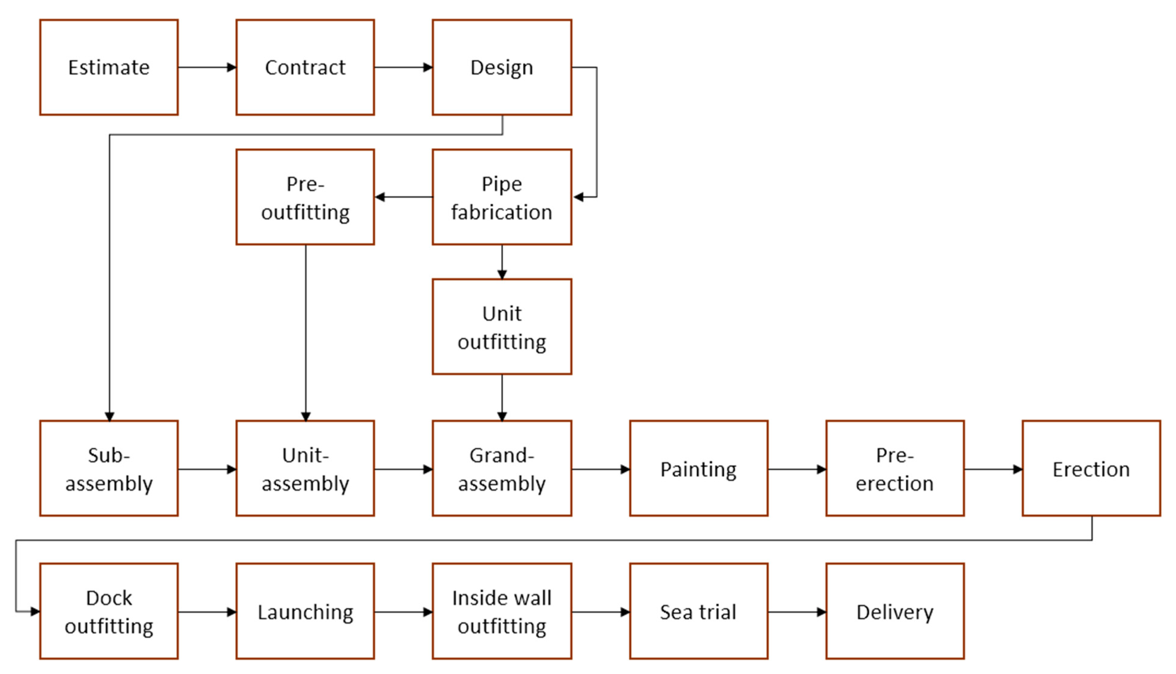
As illustrated in
Figure 1, the shipbuilding process consists primarily of design, fabrication, assembly, outfitting, painting, erection, and sea trial. The most important role in the assembly process is played by welding used in assembly, outfitting, and erection [
1]. The welding man-hour accounts for a significant portion of total shipbuilding man-hours, thus the emphasis on factors affecting the welding man-hour is unavoidably high. As a result, among the various factors influencing welding man-hours, the influence of working posture should be noted.
Many production facilities in shipyards are now being automated, as are welding operations. However, as the assembly stage progresses from sub-assembly to grand-assembly stage, it becomes practically difficult to apply automation to block assembly. Many block structures are not suitable for automated equipment to input, increasing the manual welding rate. Due to the diverse and complex working space within the block, manual welding requires various postures of the welder. The difficulty of each posture is different; therefore, the difference in working time according to the posture occurs [
2,
3,
4]. When the workload during welding is high and the proportion of difficult postures increases, so does the working time, increasing total man-hours. As a result, to create a production plan that accurately reflects the progress in assembly shops, it is necessary to identify the working posture that affects the man-hour early in the planning process and manage the plan so that the work can be completed efficiently.
In manual welding, the welder takes various postures according to the angle and position required to weld the object to the position indicated by the drawing. Manual welding is performed in the current assembly process in four positions: flat, horizontal, vertical, and overhead. The welder normally can check the assembly sequence and welding position from the drawings so that the welding position to be taken can be roughly estimated in advance. However, because the assembly sequence in the drawing may differ from the actual working shop for work efficiency, welding is frequently performed in an arbitrary position different from predicted. Such an arbitrary position in the actual field must also be recognized. Previous attempts to analyze the difference in man-hours based on welding position have been made, but it is difficult to find a study that recognizes an arbitrary position and analyzes the effect of the working posture. As a result, the majority of research has focused on recognizing human motions or working postures.
A difference from the work performed in other industrial fields is that a peculiarly external factor appears in welding. The extremely bright light of the welding arc always causes a visual disturbance, making it difficult to recognize the posture. This phenomenon is an unavoidable obstacle when using any image processing equipment, including RGB-D, and must be overcome for correct posture recognition. In this study, when shooting with an RGB-D camera, we propose a method to remove the obstructive elements from the depth image and restore the damaged image close to the original working posture. The goal is to determine the working position in real-time by detecting the welder’s posture without contact with welders and without space restrictions.
The proposed method searches for the area where the welding arc damages the depth information in the depth image using the image moment. The depth hole filling technique then restores the lost depth information. The welding position is then defined using the body joint coordinates extracted from the depth image, and the classification criteria are established. The convolution neural network (CNN), widely used for image classification among deep learning algorithms, recognizes the kind of welding position to which an arbitrary working posture belongs. The proposed method is expected to help establish a production plan related to man-hours in the shipbuilding industry.
Section 2 briefly introduces previous studies on theories and techniques used in this study. Then,
Section 3 describes the method of removing the disturbing elements from the depth image, restoring to the image without the disturbing elements, and extracting body joints from the restored image. Next, the criteria for classifying welding positions are established, and the comparison and analysis of the result of recognizing the welding positions using CNN is discussed in
Section 4, and finally, the conclusion is reached in
Section 5.
2. Previous Research
2.1. Shipbuilding Man-Hours and Welding Positions
The shipbuilding industry’s production management plan is based on construction man-hours, as such, estimating the required man-hours can help set the exact construction schedule and reduce costs. Since the beginning of time, there have been ongoing studies to establish an efficient production plan in the shipbuilding industry. Scheduling systems that consider the load of various assembly processes [
5] or those that use hierarchical architecture and spatial scheduling [
6] have been developed. Furthermore, a system for managing and predicting a shipyard’s production plan through simulation has always piqued the interest of researchers [
7].
Shipyards have relied on the observation method to directly measure the working time required for each process or task. Recently, studies have been underway to establish a set of formulas for the whole manufacturing process [
8] or to predict the man-hour for each process [
9]. Previous studies have emphasized the importance of welding by carefully considering the effects of welding operations when planning production and calculating man-hours. Since the shipbuilding process requires welding in most assembly shops, the man-hour required for the welding operation occupies a large portion. For this reason, related studies have been conducted to obtain the man-hour of welding operation in the assembly process [
1,
10]. These studies attempted to categorize postures by identifying a difference in man-hours based on working postures. Manual welding, in particular, which plays an important role in the assembly process, demonstrates that the working time varies depending on the welding position.
Many welding operations in the shipbuilding industry are currently being automated. However, as the assembly process progresses from sub-assembly to grand-assembly, the proportion of manual welding increases because automatic welding becomes difficult to apply due to limited space or complicated structural layouts.
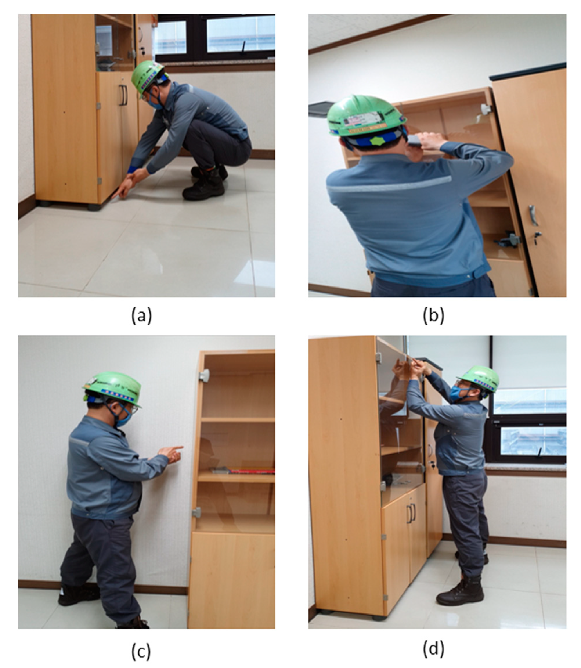
Manual welding requires various working postures. As a representative example, the American Welding Society (AWS) stipulated four general welding positions as shown in
Figure 2: flat, horizontal, vertical, and overhead. Although the above four positions are applied to welding in the shipbuilding assembly process, many different positions are observed depending on the work characteristics.
In the sub-assembly stage, the flat position ratio is high, while the vertical, horizontal, and overhead positions increase as the process progresses to the grand-assembly stage. In the grand-assembly stage, the proportion of welding posture that puts strain on the welder’s muscles increases as the working space narrows and the surrounding structure becomes more complicated. As a result, these welding positions are difficult to maintain for an extended period of time, resulting in decreased work quality or increased man-hours. Furthermore, when working for a long time, a welding position can threaten the safety and health of the worker.
Since the welding man-hour depends on the welding position, the first step is to recognize which welding position an arbitrary working posture belongs. Then, the man-hour required for block assembly can be accurately calculated. Previous studies have attempted methods such as the observation method [
11], rapid upper limb assessment (RULA) [
12], and electromyography [
13]. However, most of them were limited to the analysis of worker’s disease or safety. The purpose of this study is to suggest an automation method that remotely recognizes the working posture of a welder in the actual field in real-time, analyzes the welding position, and links it with man-hours.
2.2. Motion Capture System
To recognize a worker’s posture, it is first necessary to track the movement of the body. Recently, devices capable of tracking various types of body movements have been introduced. These motion capture systems are generally classified into a marker system, a markerless system, and a wearable system. The most accurate and reliable way is to track the body’s motion using a marker system [
14,
15,
16] that attaches a marker to each joint or a wearable sensor, such as an accelerometer or pressure sensor [
17,
18,
19]. Despite their high accuracy, markers or wearable sensors are inconvenient for the subject because separate equipment must be attached to the body ahead of time. There are also limitations to the operational range and location of those systems. Although these devices can be used for simulation in a laboratory setting, they have limitations when it comes to collecting data in a real-world setting.
A widely used method among markerless systems is to use images including depth information. Many studies have been conducted on body tracking and motion analysis using depth images [
20,
21,
22,
23]. There are two methods for creating depth images: extracting features from two-dimensional images and inferring depth through learning [
24,
25,
26,
27] or shooting with a 3D depth camera [
28,
29,
30]. The former method has disadvantages in that an additional process is required to extract and learn features of an image, it takes a lot of time, and the accuracy is low.
A 3D depth sensor has been widely used to take a depth image. There are two types of 3D depth sensors: time of flight (ToF) and LiDAR. The ToF sensor calculates depth information by measuring the time it takes to emit infrared rays and return. This sensor is mainly used for motion capture because of its high accuracy [
31,
32]. Similar to the ToF sensor, the LiDAR sensor generates a depth image by measuring the return time after firing a laser. Some studies track body motion using the LiDAR sensor, but its accuracy is reported to be low [
33,
34]. Furthermore, since motion capture using a LiDAR sensor not only requires a separate RGB camera but has been slow to commercialize, its applicability is currently low [
35].
This study focuses on improving accessibility, portability, and accuracy to collect motion data for posture recognition in real-time. We selected an RGB-D camera based on ToF sensors with cost-effectiveness and excellent usability in the current market. The selected Azure Kinect provides clear resolution and high accuracy through the ToF method using an IR projector and depth sensor [
36].
2.3. Depth Hole Filling
The ToF sensor creates the depth image by measuring the round-trip time of the infrared signal emitted by the IR projector. This method calculates depth by emitting infrared light, thus it is greatly influenced by weather factors such as light, rain, fog, and environmental factors such as the strength of lighting scattering. As a result, the depth measured by the ToF sensor is inaccurate [
37] in the aforementioned environment. It has also been reported that the same type of LiDAR sensor reduces depth calculation accuracy due to ambient lighting and disturbance factors [
38,
39]. As a result, obtaining a depth image using the above sensors is limited when a light source is stronger than necessary.
Various welding methods used in assembly sites include arc, gas, laser, and explosion welding.
welding, which is mainly used in shipbuilding shops, inevitably generates an arc that emits bright light, as shown in
Figure 3.
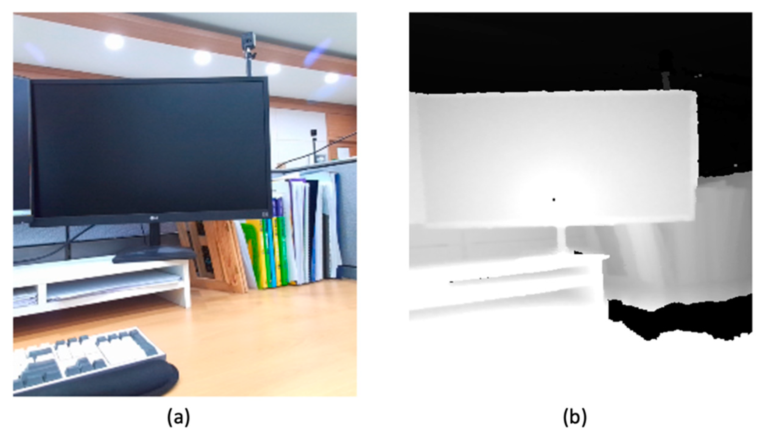
RGB-D cameras have a limitation in being greatly affected by bright sources such as welding arcs. Therefore, when shooting a welding worker, an arc causes the RGB-D camera to fail to measure the reflected signal, resulting in a region where depth information is lost in the depth image. This region is classified as undefined as the area where the RGB-D camera cannot define depth. For example, the undefined region is defined as a depth hole in the depth image and is expressed in black as shown in the right scene of
Figure 4.
When the welding arc and the welder’s body overlap, it is difficult to capture motion accurately because the depth hole obscures the body in the depth image captured by an RGB-D camera. To recognize the body motion or working posture, we must look for a depth hole caused by the welding arc and remove it if it is found.
In previous studies, image inpainting techniques [
40,
41] and image filtering methods [
42,
43,
44] were used to care for depth holes. Image filtering is an operation that creates a new image by using a square matrix and a convolution technique. A guidance image converted from an RGB image to grayscale is required to remove the depth hole using image filtering. However, a guidance image without a welding arc is unavailable in advance for a welding operation in progress, so utilizing the image filtering is not practical.
Image inpainting is, in theory, a technique for repairing damaged areas of an image. Normally, the depth image’s depth holes are searched for and removed. However, in this study, where motion capture accuracy is critical, high accuracy can be obtained even when only the depth hole caused by the interference element is removed. Furthermore, while the depth hole filling speed is adequate for a small amount of image data, removing all of the depth holes for each frame of moving images takes a significant amount of computing time. As a result, data processing speed should be prioritized.
In this study, an image inpainting technique is adopted as a method to remove depth holes. Furthermore, we present a method to search only the depth hole that overlaps the body among the depth holes generated in the depth image.
2.4. Machine Learning Technique for Posture Recognition
Many fields are actively researching posture recognition for worker safety, musculoskeletal disorders, and posture correction. In industries, these studies include the development of a production plan and the enhancement of productivity. A wide range of fields, from the human posture classification field considering simple postures such as sitting, standing, and lying down [
45,
46] to the medical [
47,
48], industrial [
49], and sports [
50] fields, have focused on the definition and recognition of human postures. As hardware for collecting posture recognition data, three-dimensional depth cameras [
51], smartphones [
52,
53], and inertial measurement unit sensors [
17] are used. In addition, machine learning algorithms such as support vector machine (SVM) [
54], CNN [
19], and deep belief network [
55] are widely used to learn posture recognition data in terms of software.
CNN is a well-known machine learning technique that has been widely applied to image classification and recognition. This technique is currently used for image classification [
56] and object detection [
57] in the shipbuilding industry for safety management and productivity improvement. There is no need to manually extract features because CNN learns the features of an object through data. It also has good reusability because it can learn new data based on the existing network. This study proposes a CNN model as a data learning algorithm for the reasons of convenience, reusability, and efficiency.
3. Depth Image Analysis and Body Joint Identification
3.1. Depth Hole Detection
An image including depth information of the welder’s body must be captured with an RGB-D camera to recognize a welding position by extracting body joints. As described earlier, when a welding operation is taken with an RGB-D camera, bright light is generated due to the welding arc, and as a result, a wide range of depth holes are generated.
We are interested in the proportion of manual welding’s vertical and horizontal welding positions that gradually increases with each assembly step during the assembly process. Because most of the welding for these two positions is done in front of the welder’s own body, the depth hole region caused by the arc occurs around the body. As a result, the distinction between the body and the arc is blurred, making it impossible to recognize the exact joint positions, as shown in
Figure 5. Therefore, to capture motion for those welding positions, a process of removing depth holes is required.
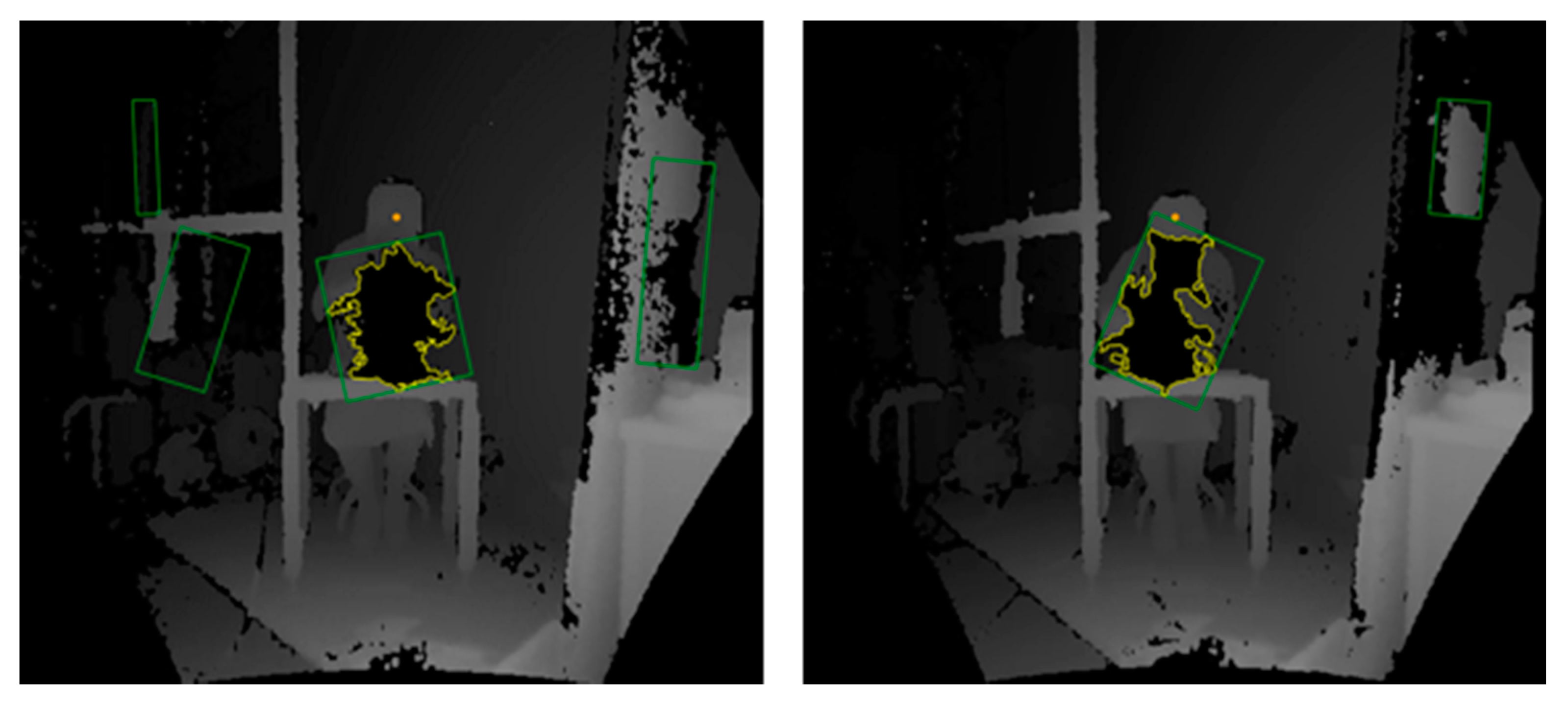
Before removing the depth hole, it is necessary to identify the depth hole that overlaps the body in the depth image. Since welding is carried out in front of the welder for safety, if the scene is taken with an RGB-D camera, the welder’s body appears as a shape surrounding the depth hole, as shown in
Figure 6. Therefore, we use this characteristic to detect the depth hole.
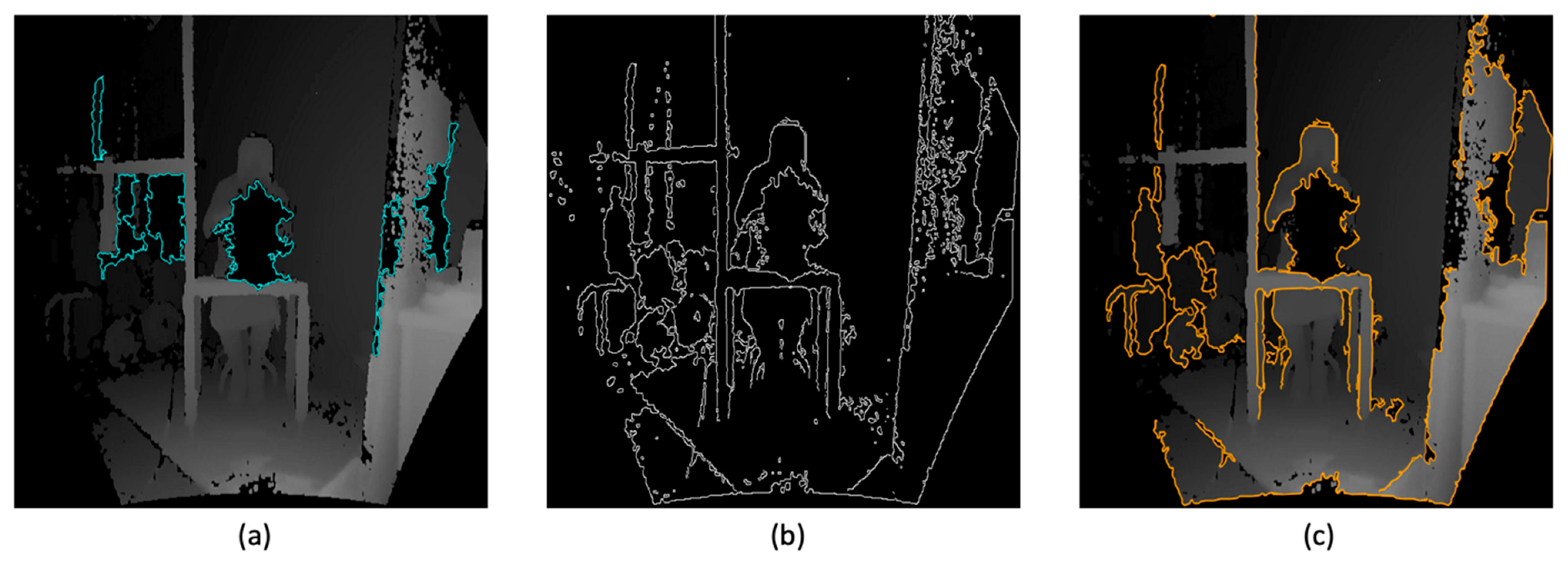
To isolate the depth hole from the body, the depth hole region must be searched. Because the depth hole is recorded as an undefined region in the depth image, the depth hole region can be specified using image pixel analysis. To improve search efficiency, depth holes of a certain size or less are excluded in this case. We use the fact that the rate of change of brightness occurs in the body’s outline to isolate a body part from the surrounding environment. Canny edge detection [
58], which is effective for detecting the rate of change of brightness, is utilized. The result of the searched depth hole and the object separated from the background are visualized in
Figure 7. A plurality of regions recognized as depth holes exists around the welder.
It is necessary to find the depth hole that exists inside the welder’s body, among many depth holes found. In this study, the centroid of an object is utilized by following the rule that the body surrounds the depth hole. The proposed assumption is that the contour of the depth hole, if any, is in most cases tangent to or inside the body contour. In this case, the rectangle circumscribing the depth hole will cover more than half of the body contour area. If the depth hole inside the rectangle circumscribes the object’s centroid estimated as the body contour, it becomes a depth hole overlapping the body. Otherwise, it is treated as noise. Due to the nature of the arc, an exception may occur where a part of the depth hole contour is outside the body contour. Even in this case, the exceptional effect is greatly reduced and ignored with the proposed assumption.
The centroid of the object contour is simply obtained from the spatial moment Equation (1):
where
denotes the general form of the spatial moment,
the zero-order moment of the image,
the first-order moment of the image concerning the
x-axis, and
the first-order moment of the image concerning the
y-axis. The red dots indicate the centroids of all objects separated from the background in
Figure 8.
Many pieces of equipment or objects are arranged near the welding space in an actual welding site. In the depth image, objects at a similar distance to the welder have a brightness similar to that of the welder’s body. Even when the Canny edge algorithm is used in this case, objects with similar brightness and the welder’s body can be recognized as the same object, implying that the background and body are not completely separated. As shown in
Figure 9, there are cases where several rectangles circumscribed in the depth hole are searched. With these rectangles, checking the centroid of the object’s contour alone is not sufficient to determine whether the object is the body or not.
To solve this problem, a unique feature of welding is used. To ensure their safety, welders generally perform their work as far away from the body as possible. At this point, the welder’s head naturally moves away from the arc, and as a result, the depth hole has little effect on the welder’s head. This feature makes determining the welder’s head position simple. Among the many depth holes suspected of overlapping the body, the depth hole closest to the head coordinate is selected in
Figure 10.
3.2. Depth Hole Filling
After selecting the depth hole due to the arc, the image occupied by the depth hole should be replaced with a body image. In this study, the image inpainting technique is used to restore the depth hole by specifying it as a mask and filling it with a color similar to the surrounding color [
59]. Starting from the contour of the selected depth hole, the color is restored toward the inside of the depth hole. The color to be restored uses the pixel’s color value in the area adjacent to the depth hole. The depth hole can be restored to color values expressed by (2) that was used in the fast marching method by Telea [
59]:
where
is the pixel of the region to be restored,
is the pixel of the neighboring region,
is the color value of the neighboring region,
is the gradient, and
is the neighboring region with respect to
, respectively.
Figure 11 shows the restored image where the depth hole around the welder is eliminated.
3.3. Two-Dimensional Body Joint Identification
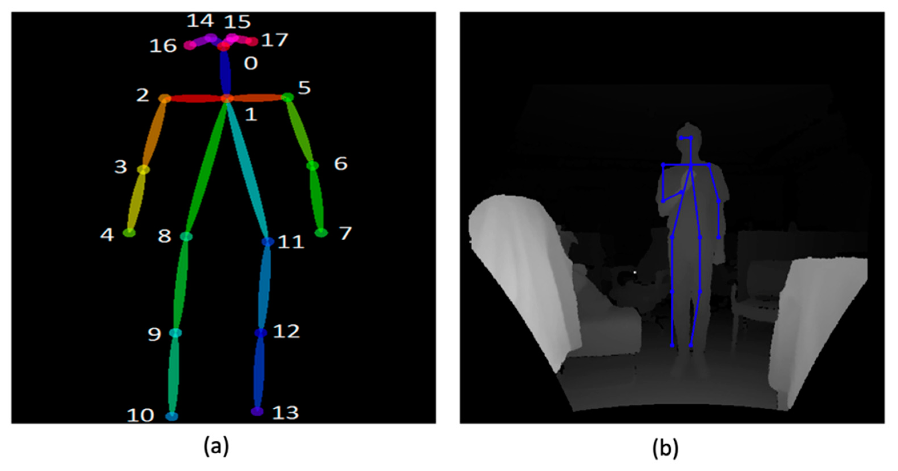
Body joints can be extracted from the restored image where the depth hole is cured. Since the restored image is two-dimensional, we can use various methods for extracting joints from images. In this study, OpenPose [
60], a widely used open source, is used. The joint coordinate structure [
61] we adapt is shown in the left figure of
Figure 12. An example of the body joints extracted corresponding to the structure is illustrated in the right figure.
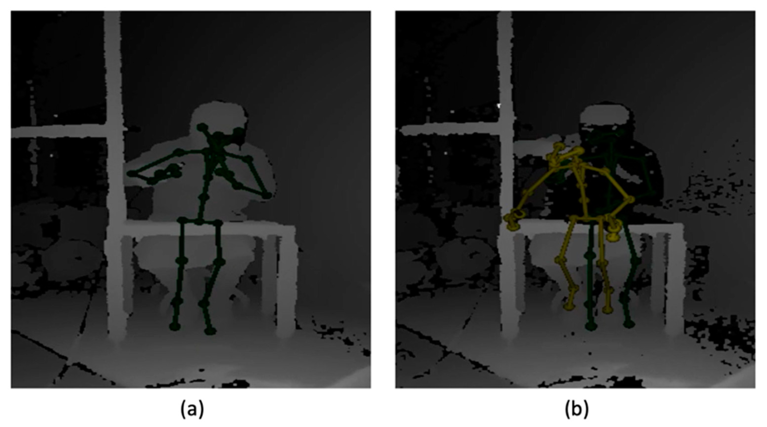
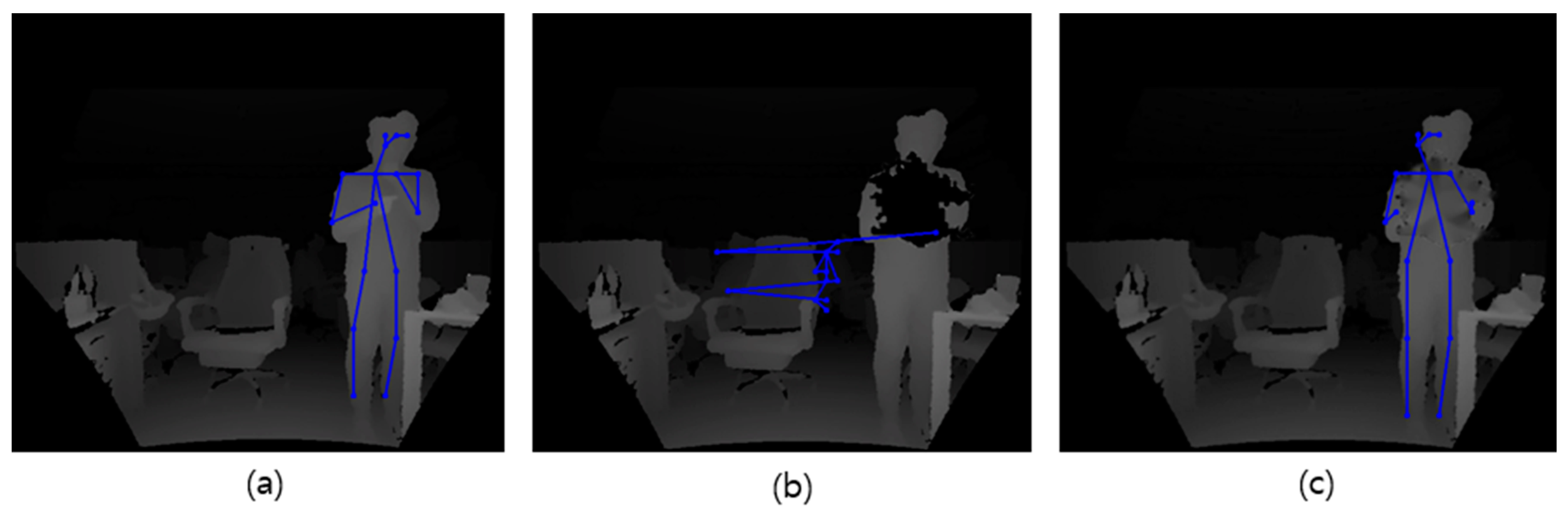
Body joints extracted from two-dimensional images cannot always be accurate. The cause of inaccurate results may be an inherent problem of the depth camera or other obstacles such as measurement errors, interference by the measurement environment, and even the incompleteness of the joint extraction module. An incorrect result caused by the camera error is shown in
Figure 13b. In this case, it is risky to trust the result of joint information using only a single image. Instead, we set up an assumption that the video stream obtained from the depth camera is continuous and enables a ground truth shown in
Figure 13a. Then, we correct the joint coordinates for a frame in question by interpolating the frames before and after the corresponding frame. The interpolation result is shown in
Figure 13c, and it is almost consistent with the ground truth.
3.4. Three-Dimensional Body Joint Construction
Joint coordinates extracted from depth hole filled images cannot provide accurate depth information. Welding, as opposed to general body postures, necessitates complex joint movement. The rotation of the arm, neck, and waist joints appears on a vertical or horizontal basis when performing a welding operation, making it only possible to correctly express a welding posture when accurate depth information is provided. As a result, proper depth information must be included.
The depth image is expressed in grayscale according to the distance from the depth sensor. Joints far from the sensor are displayed as dark, while those close to the sensor are displayed as bright. Therefore, when the welding operation is taken as a depth image, the welder’s body and surrounding objects are expressed as images with different color values according to the distance difference.
In this study, a strategy is used to restore the joint coordinates damaged by the depth hole in the depth image by utilizing the measured depth information of the body part that is not covered. Given that the depth hole has a significant impact on the welder’s arm and body due to welding characteristics, if there is a part of the arm or body for which depth information is measured, the depth hole region is sequentially interpolated and reconstructed using the depth information available. This strategy assumes that recognizing the welding position requires only the relative positional relationship of the joints.
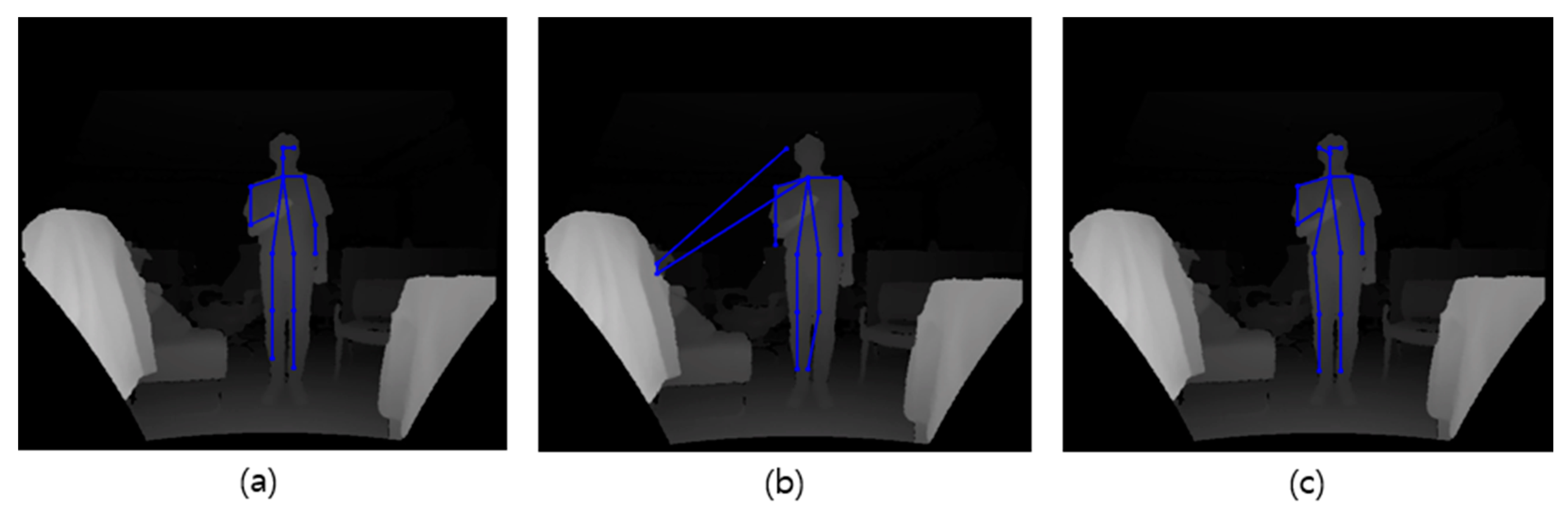
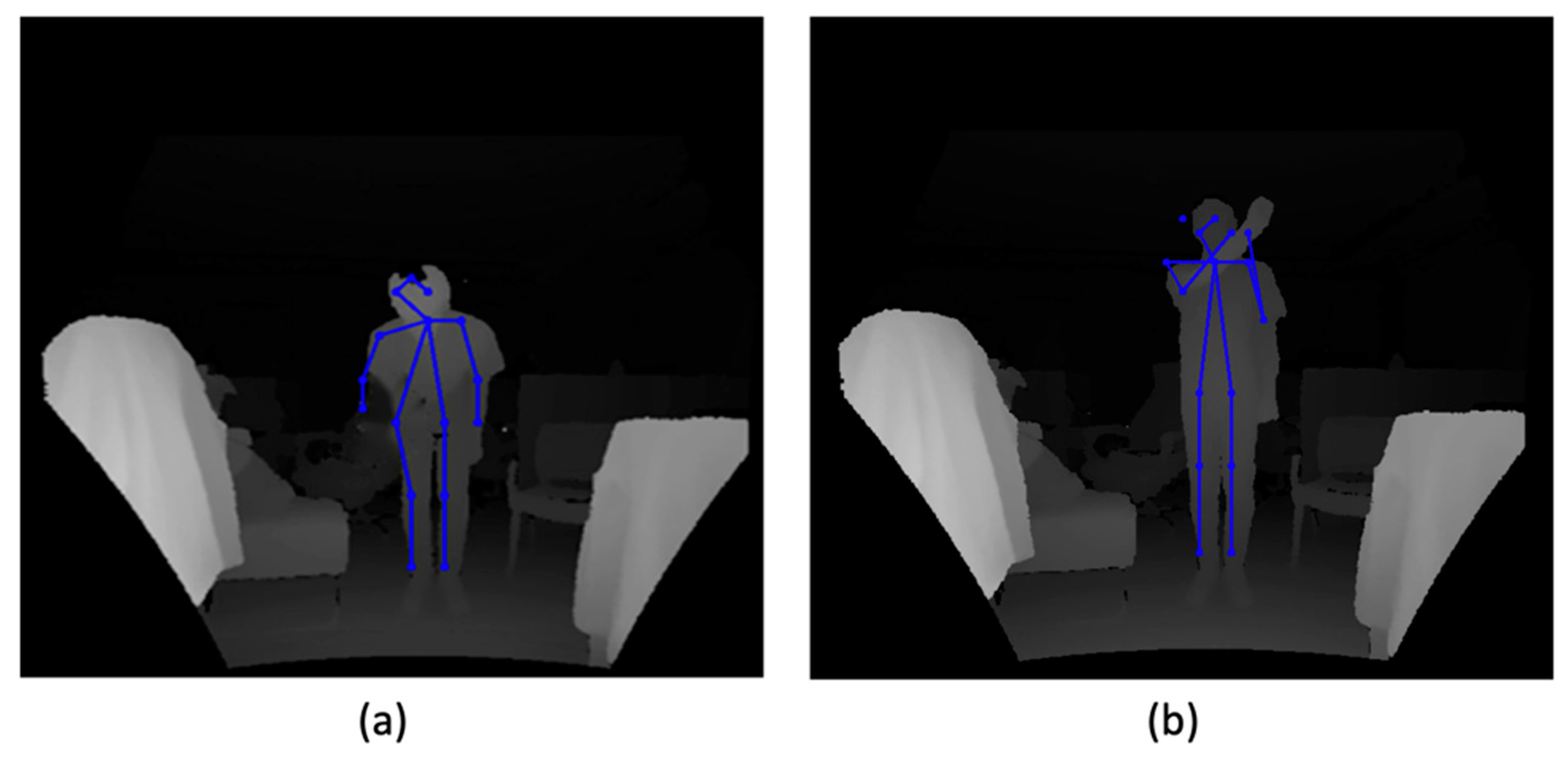
Figure 14 shows the results of comparing the joints extracted using (a) the ground truth without depth hole, (b) the image with the depth hole, and (c) the image with the depth hole removed. The joint coordinate values can be checked in
Table 1, where the error is computed by the difference in the two vectors’ magnitude. The joint coordinates extracted from (a) and (c) images do not show a large error. In (c), an error occurs near the neck and hand that were hidden by the depth hole. Unfortunately, this is a theoretically unavoidable limit. The correlation with other joints is still well maintained.
4. Welding Position Recognition
The analysis of four welding positions was observed during the shipbuilding assembly process. Criteria for classifying a given welding position are established by utilizing the relative relationship of body joint coordinates. When collecting depth image data, these criteria are used in the data labeling process. In addition, CNN, a machine learning technique, is used for posture recognition.
4.1. Classification of Welding Positions
When a welder performs an arbitrary welding operation, determining a standard capable of distinguishing which welding position is taken is required. This study proposes criteria for classifying the welding positions using the positional relationship of the extracted coordinates of body joints.
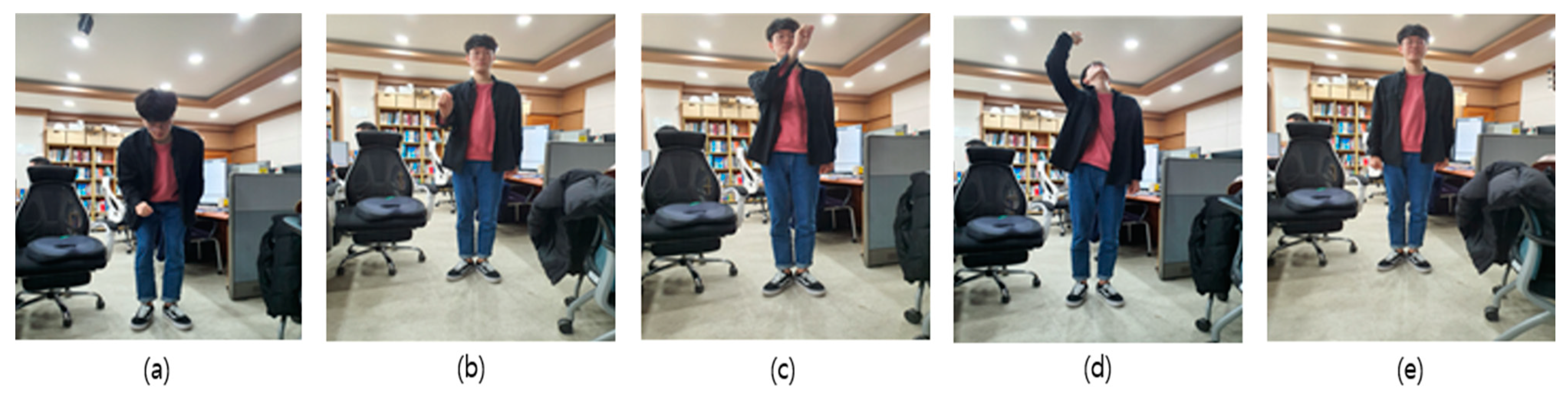
The welding positions to be recognized are based on the standard postures stipulated by the AWS, the data and advice collected from shipyards, and our simulation. Five positions were defined as flat, horizontal, vertical, overhead, and standing. A representative example of the five positions is shown in
Figure 15.
Since the welding position can be distinguished by the movement of the upper body, arm, and hand holding the welding rod, six joints such as head, neck, shoulder, elbow, hand, and pelvis are chosen as main measurement elements. In this study, a method of classifying five positions using the relative relationship of six joint coordinates is proposed in
Figure 16.
Based on the standing position, a different position is determined whenever the positional relationship of the six joint coordinates changes. For example, as shown in
Figure 17, when the coordinates of the neck joint are located farther from the sensor than those of the head joint, and the coordinates of the hand joint are higher than those of the waist joint, it is classified as a flat position. Similarly, when the hand joint is located higher than the neck joint, and the hand joint is positioned to the left of the right shoulder joint for a right-handed person, as shown in
Figure 17b, it becomes a horizontal position. Therefore, before proceeding with learning, the data labeling process that specifies the welding position is performed through the criteria set above.
4.2. Use of Convolution Neural Network
An algorithm that automatically recognizes the classified welding position is necessary. Considering that position recognition is a classification domain that distinguishes different postures, the SVM [
54]), which is the most used model in classification problems, was first considered. SVM is a model that maximizes the distance of the data closest to the decision boundary. To recognize a position with the SVM, body features such as the coordinates or angles of the joints are used as learning data. However, accurate coordinate values from the depth image were not available in this study, hence jeopardizing SVM use.
Another machine learning model considered is the CNN. CNN is a deep learning model with multiple convolutional layers and is most often used in classification problems, especially for image classification. Since CNN learns image features using image data, there is no need for a separate feature extraction process. Therefore, an approach to recognizing welding positions with a CNN model is appropriate.
We used the GoogLeNet network [
62] to train the depth image data. This network becomes deep by introducing the Inception network structure but has the advantage that the amount of computation does not increase significantly because the number of parameters is reduced. It is widely used in image classification problems and is divided into several versions, such as Inception v1, v2, v3, v4, and ResNet. In this study, the welding position is recognized using the pre-trained Inception v3 model. This model uses the Inception module, as shown in
Figure 18, to construct the network structure. Unlike the previous versions, the amount of computation is reduced by the asymmetric convolutional decomposition method.
4.3. Data Collection
A commercially available depth camera was used to capture the learning image. However, it was impossible to film at the actual shipyard due to safety and security concerns, so a detour strategy was used to create an experimental environment in the laboratory. The laboratory environment was designed to be as close to a real job shop as possible, complete with keeping equipment and obstacles.
The camera was installed 1.20 m above the ground, and the experiment was conducted at 3.50 m. For six right-handed adult male subjects, images of five positions were recorded. Subjects received short-term advice and training on welding and the required postures from a welding expert in advance. Following research ethics procedures, prior written consent was made from all participants.
Each working posture was photographed for ten seconds, and the images were divided into 30 frames per second, and a total of 9000 image data were collected for the five welding positions. Thus, a total of 18,000 data were collected, including 9000 image data including depth holes and 9000 restored image data with depth hole filling by the method presented in this study,
Table 2 shows selected examples of the depth images of the data set. In the figure, the depth hole in the overhead is intentionally not removed.
4.4. Recognition of Welding Positions
The acquired 18,000 depth image dataset was divided into training set, validation set, and test set at a ratio of 6:2:2 and trained on the Inception v3 model. Learning was carried out using a model pre-trained with a visual database, ImageNet, and then fine-tuned on a depth image dataset. The loss function is defined as (3):
where
is the probability of belonging to the i-th class,
is the ground truth, and
is the softmax function that expresses the probability of belonging to the ground truth. The smaller the value of the loss function, the better the model performance.
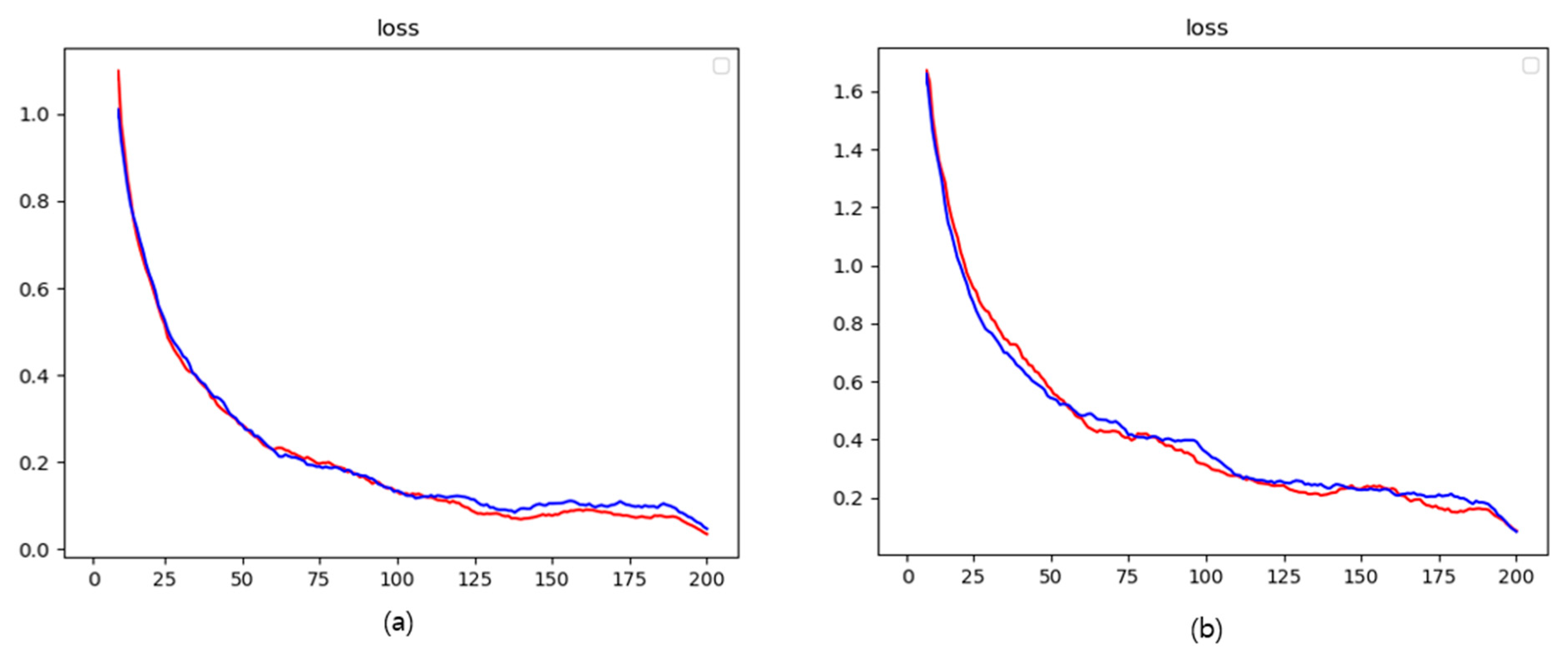
The training was repeated 200 times to measure the accuracy and loss function values, and the results are graphically shown in
Figure 19 and
Figure 20. The final accuracy and loss values are 94.84% and 0.1012 for the validation data with depth holes and 98.96% and 0.0562 for those with depth hole fillings.
The computational environment used when running the CNN model as well as the algorithm proposed in this study is as follows:
- ○
Intel i7-10700K @ 3.80 GHz;
- ○
16 GB RAM;
- ○
NVIDIA GeForce RTX 3070.
The Inception v3 used as a CNN model consists of 42 layers. The last output layer was configured to be classified into 5 classes using the softmax as an activation function. It took about 15 min to train 200 times each for the two cases of (1) images with deep holes, and (2) images with reconstructed deep holes.
The accuracy of the test data is compared in
Table 3. This result reveals that the recognition accuracy of the welding positions improves when the depth hole caused by the arc is removed and restored.
The result of training the depth image on CNN showed higher accuracy than that of training on SVM. The SVM, which analyzed the necessary data from extracted joint coordinates, could not accurately produce the coordinates of the body parts that overlapped the depth hole in flat, vertical, and horizontal positions. The decisive cause is that when any inaccurate joint coordinate exists, the linked joints are not properly calculated due to the hierarchical structure in which the joints of all parts are strictly connected. For this reason, no matter how much training is performed with SVM, the decision boundary to accurately divide the class is not determined, resulting in relatively low accuracy.
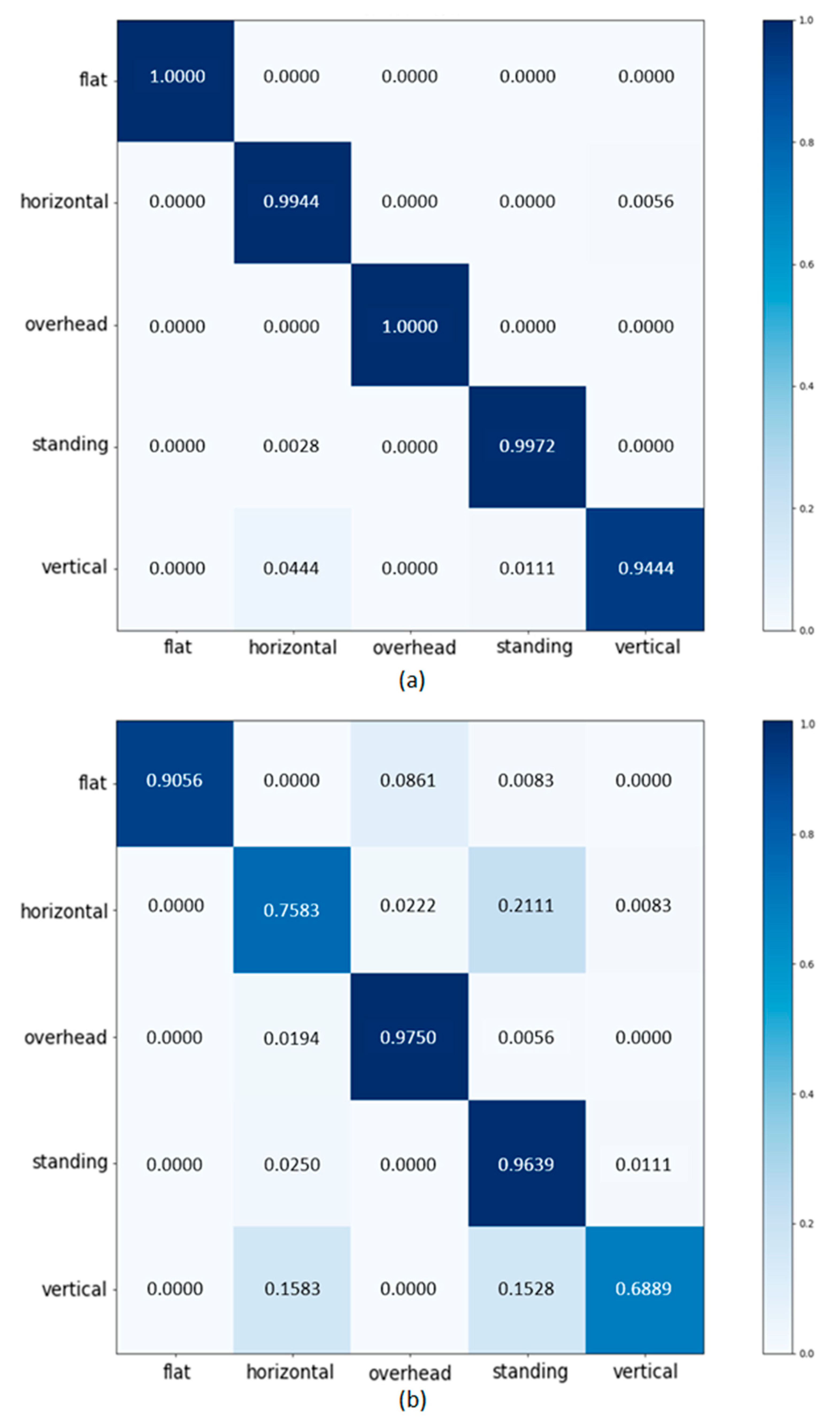
The CNN results for one dataset with depth holes and another dataset with depth hole filling are compared in a confusion matrix in
Figure 21. Both datasets show considerable accuracy for the overhead and standing positions where the depth hole does not cover the welder’s body. On the other hand, in flat, vertical, and horizontal positions where the body and the depth hole overlap, the accuracy in the dataset with the depth hole is significantly lower. As a result, to recognize the correct posture in a welding operation where an obstructive element exists, the cause of the obstructive element must be removed in advance.
4.5. Limitations
Since the size of the welding arc varies, the depth hole region in the depth image caused by the arc varies as well. Because a small depth hole exists inside the welder’s body, the method presented in this study can be used to search for and remove it. On the other hand, a large depth hole that expands out of the body or intermittently overlaps with the undefined regions around the welder makes it difficult to define the correct range of the depth hole, as shown in
Figure 22a,b. In
Figure 22c, a depth hole occurs in a large size that covers both the whole arm and the upper body. In this case, the color necessary for the restoration of the arm cannot be used. In the process of restoring the color, it is impossible to extract the joint of the arm because both the upper body and the arm are restored to the body color.
As a result of observing the actual welding operation, the depth hole caused by the welding arc is rarely larger than the welder’s body, but the possibility cannot be ignored. The limitations should be resolved in future studies to recognize and analyze the welding position in the actual field.
When watching the actual welding operation, there are times when the welder’s hand is higher than the neck in a horizontal position. The depth hole in this position is mostly found on the neck or upper part of the upper body, but it can extend all the way to the head depending on the individual’s working habits. As a result, in this case, the head position cannot be specified. Future research is expected to solve the problem by locating alternative joints, such as the neck and chest, rather than the head.
5. Conclusions
Since frequent manual welding in the shipbuilding assembly process produces different man-hours depending on the working posture, a technique capable of measuring and analyzing the working posture in advance is required. In this study, a method for recognizing working postures using RGB-D cameras was proposed.
A method for resolving the problem of difficult welding position recognition due to the welding arc was presented. We created an algorithm that searches for depth holes in two-dimensional depth images and removes them using the image moment and the image inpainting technique. Two-dimensional coordinates of body joints were extracted from depth images and combined with depth information to create three-dimensional joints using open-source software. Those joints were used to establish a standard for welding positions, and the working postures were recognized and classified based on the standard. The method proposed in this study consists of (1) excluding direct contact or interference with field workers, (2) acquiring data through remote sensing based on an RGB-D camera, (3) recognizing posture using a pre-trained CNN model, and (4) determining the working position in real-time. Thus, the proposed method could provide an efficient tool for measuring and recognizing the working posture in the field using an inexpensive depth camera, by automatically eliminating the disturbance factors of the image. Instead of removing all depth holes from the depth image, we were able to obtain a performance improvement of more than 40% by removing only the necessary parts.
The coordinates of joint extracted from the restored image and those of the ground truth showed a similar tendency overall. The error of the hand and neck joints covered by the depth hole was large, but the correlation between the joints did not change significantly. As a result of classifying the working position by learning the preprocessed depth image on the CNN model, high accuracy of 98.72% was obtained. This shows 13% points higher performance than the 85.83% accuracy of the depth image without preprocessing.
The proposed method can be used in shipbuilding and other industries that require a variety of working postures. Analyzing working postures with high workloads can help prevent accidents and musculoskeletal disorders in workers. Assume, for example, that the recognized welding position is reflected in the formula used to calculate welding man-hours. In that case, it can assist the shipyard in calculating realistic man-hours and thus managing an efficient production schedule.
Interference factors caused by bright light may occur in the field in the electrical, electronic, and optical industries. Furthermore, because construction and sports happen outside, motion capture accuracy may suffer. Thus, the findings of this study are expected to help detect external disturbances or recognize work postures in other industries where accurate depth images are impossible to obtain due to potential disturbances.
Author Contributions
Conceptualization, J.-H.N.; methodology, J.-H.K. and J.-H.N.; software, J.-H.K.; validation, J.-H.K.; formal analysis, J.-H.K. and J.-H.N.; investigation, J.-H.N.; resources, J.-H.K.; data curation, J.-H.K.; writing—original draft preparation, J.-H.K. and J.-H.N.; writing—review and editing, J.-H.N.; visualization, J.-H.K.; supervision, J.-H.N.; project administration, J.-H.N.; funding acquisition, J.-H.N. All authors have read and agreed to the published version of the manuscript.
Funding
This research was supported in part by the project “Development of master data system of lead time for precision enhancement of shipbuilding production management (project ID: 20000208),” sponsored by the Ministry of Trade, Industry, and Energy of Korea.
Institutional Review Board Statement
Not applicable.
Informed Consent Statement
Not applicable.
Data Availability Statement
The study did not report any data.
Conflicts of Interest
The authors declare no conflict of interest.
References
- Cho, K.-K.; Sun, J.-G.; Oh, J.-S. An automated welding operation planning system for block assembly in shipbuilding. Int. J. Prod. Econ. 1999, 60–61, 203–209. [Google Scholar] [CrossRef]
- Ariyanti, S.; Widodo, L.; Zulkarnain, M.; Timotius, K. Design Work Station of Pipe Welding with Ergonomic Approach. Sinergi 2019, 23, 107. [Google Scholar] [CrossRef]
- Zhang, Y.; Wu, X.; Gao, J.; Chen, J.; Xv, X. Simulation and Ergonomic Evaluation of Welders’ Standing Posture Using Jack Software. Int. J. Environ. Res. Public Health 2019, 16, 4354. [Google Scholar] [CrossRef] [PubMed] [Green Version]
- Susihono, W.; Selviani, Y.; Dewi, I.A.K.A.; Liswahyuningsih, N.L.G. Musculoskeletal and Postural Stress Evaluation as a Basic for Ergonomic Work Attitudes on Welding Workers. In Proceedings of the 3rd International Conference on Innovative Research Across Disciplines (ICIRAD 2019); Atlantis Press: Denpansar, Indonesia, 2020. [Google Scholar] [CrossRef] [Green Version]
- Cho, K.; Oh, J.; Ryu, K.; Choi, H. An Integrated Process Planning and Scheduling System for Block Assembly in Shipbuilding. CIRP Ann. 1998, 47, 419–422. [Google Scholar] [CrossRef]
- Lee, J.K.; Lee, K.J.; Park, H.K.; Hong, J.S.; Lee, J.S. Developing scheduling systems for Daewoo Shipbuilding: DAS project. Eur. J. Oper. Res. 1997, 97, 380–395. [Google Scholar] [CrossRef]
- Alfeld, L.E.; Pilliod, C.S.; Wilkins, J.R. The Virtual Shipyard: A Simulation Model of the Shipbuilding Process. J. Ship Prod. 1998, 14, 33–40. [Google Scholar] [CrossRef]
- Choi, W.-S.; Kim, D.-H.; Nam, J.-H.; Kim, M.-J.; Son, Y.-B. Estimating Production Metric for Ship Assembly Based on Geometric and Production Information of Ship Block Model. J. Mar. Sci. Eng. 2021, 9, 39. [Google Scholar] [CrossRef]
- Hur, M.; Lee, S.-K.; Kim, B.; Cho, S.; Lee, D.; Lee, D. A study on the man-hour prediction system for shipbuilding. J. Intell. Manuf. 2013, 26, 1267–1279. [Google Scholar] [CrossRef]
- Pribadi, T.W.; Shinoda, T. Hand Motion Recognition of Shipyard Welder Using 9-DOF Inertial Measurement Unit and Multi Layer Perceptron Approach. IOP Conf. Ser. Earth Environ. Sci. 2020, 557, 012009. [Google Scholar] [CrossRef]
- Wahyuni, D.; Budiman, I.; Sembiring, M.T.; Sitorus, E.; Nasution, H. The workload analysis in welding workshop. IOP Conf. Ser. Earth Environ. Sci. 2018, 126, 012095. [Google Scholar] [CrossRef]
- Ramli, R. Work Posture Analysis of Welding Workers Using the RULA Method. J. Medihealtico 2020, 1, 8–12. [Google Scholar] [CrossRef]
- Lowe, B.D.; Wurzelbacher, S.J.; A Shulman, S.; Hudock, S.D. Electromyographic and discomfort analysis of confined-space shipyard welding processes. Appl. Ergon. 2001, 32, 255–269. [Google Scholar] [CrossRef]
- Canton-Ferrer, C.; Casas, J.R.; Pardàs, M. Marker-Based Human Motion Capture in Multiview Sequences. EURASIP J. Adv. Signal Process. 2010, 2010, 105476. [Google Scholar] [CrossRef] [Green Version]
- Han, S.; Liu, B.; Wang, R.; Ye, Y.; Twigg, C.D.; Kin, K. Online optical marker-based hand tracking with deep labels. ACM Trans. Graph. 2018, 37, 1–10. [Google Scholar] [CrossRef] [Green Version]
- Kolahi, A.; Hoviattalab, M.; Rezaeian, T.; Alizadeh, M.; Bostan, M.; Mokhtarzadeh, H. Design of a marker-based human motion tracking system. Biomed. Signal Process. Control. 2007, 2, 59–67. [Google Scholar] [CrossRef]
- Chen, J.; Qiu, J.; Ahn, C. Construction worker’s awkward posture recognition through supervised motion tensor decomposition. Autom. Constr. 2017, 77, 67–81. [Google Scholar] [CrossRef]
- Miezal, M.; Taetz, B.; Bleser, G. On Inertial Body Tracking in the Presence of Model Calibration Errors. Sensors 2016, 16, 1132. [Google Scholar] [CrossRef]
- Tang, K.; Kumar, A.; Nadeem, M.; Maaz, I. CNN-Based Smart Sleep Posture Recognition System. IoT 2021, 2, 119–139. [Google Scholar] [CrossRef]
- Han, S.; Achar, M.; Lee, S.; Peña-Mora, F. Empirical assessment of a RGB-D sensor on motion capture and action recognition for construction worker monitoring. Vis. Eng. 2013, 1, 6. [Google Scholar] [CrossRef] [Green Version]
- Le, T.-L.; Nguyen, M.-Q.; Nguyen, T.-T.-M. Human Posture Recognition Using Human Skeleton Provided by Kinect. In 2013 International Conference on Computing, Management and Telecommunications (ComManTel); IEEE: Ho Chi Minh City, Vietnam, 2013; pp. 340–345. [Google Scholar] [CrossRef]
- Singh, R.; Khurana, R.; Kushwaha, A.K.S.; Srivastava, R. Combining CNN streams of dynamic image and depth data for action recognition. Multimed. Syst. 2020, 26, 313–322. [Google Scholar] [CrossRef]
- Diego-Mas, J.A.; Alcaide-Marzal, J. Using Kinect™ sensor in observational methods for assessing postures at work. Appl. Ergon. 2014, 45, 976–985. [Google Scholar] [CrossRef] [Green Version]
- Liu, B.; Gould, S.; Koller, D. Single image depth estimation from predicted semantic labels. In Proceedings of the 2010 IEEE Computer Society Conference on Computer Vision and Pattern Recognition, San Francisco, CA, USA, 13–18 June 2010; pp. 1253–1260. [Google Scholar] [CrossRef] [Green Version]
- Jiang, G.; Jin, S.; Ou, Y.; Zhou, S. Depth Estimation of a Deformable Object via a Monocular Camera. Appl. Sci. 2019, 9, 1366. [Google Scholar] [CrossRef] [Green Version]
- He, L.; Yang, J.; Kong, B.; Wang, C. An Automatic Measurement Method for Absolute Depth of Objects in Two Monocular Images Based on SIFT Feature. Appl. Sci. 2017, 7, 517. [Google Scholar] [CrossRef] [Green Version]
- Zhang, W.; Liu, Z.; Zhou, L.; Leung, H.; Chan, A.B. Martial Arts, Dancing and Sports dataset: A challenging stereo and multi-view dataset for 3D human pose estimation. Image Vis. Comput. 2017, 61, 22–39. [Google Scholar] [CrossRef]
- Chen, Y.; Zhou, W. Hybrid-Attention Network for RGB-D Salient Object Detection. Appl. Sci. 2020, 10, 5806. [Google Scholar] [CrossRef]
- Kang, X.; Li, J.; Fan, X.; Wan, W. Real-Time RGB-D Simultaneous Localization and Mapping Guided by Terrestrial LiDAR Point Cloud for Indoor 3-D Reconstruction and Camera Pose Estimation. Appl. Sci. 2019, 9, 3264. [Google Scholar] [CrossRef] [Green Version]
- Quan, L.; Li, H.; Li, H.; Jiang, W.; Lou, Z.; Chen, L. Two-Stream Dense Feature Fusion Network Based on RGB-D Data for the Real-Time Prediction of Weed Aboveground Fresh Weight in a Field Environment. Remote Sens. 2021, 13, 2288. [Google Scholar] [CrossRef]
- Ganapathi, V.; Plagemann, C.; Koller, D.; Thrun, S. Real Time Motion Capture Using a Single Time-of-Flight Camera. In 2010 IEEE Computer Society Conference on Computer Vision and Pattern Recognition; IEEE: San Francisco, CA, USA, 2010; pp. 755–762. [Google Scholar] [CrossRef]
- Routray, J.; Rout, S.; Panda, J.J.; Mohapatra, B.S.; Panda, H. Hand Gesture Recognition using TOF camera. Int. J. Appl. Eng. Res. 2021, 16. [Google Scholar] [CrossRef]
- Yoon, S.; Jung, H.-W.; Jung, H.; Kim, K.; Hong, S.K.; Roh, H.; Oh, B.-M. Development and Validation of 2D-LiDAR-Based Gait Analysis Instrument and Algorithm. Sensors 2021, 21, 414. [Google Scholar] [CrossRef]
- Yoon, J.-S.; Bae, S.-H.; Kuc, T. Human Recognition and Tracking in Narrow Indoor Environment Using 3D Lidar Sensor. In 2020 20th International Conference on Control, Automation and Systems (ICCAS); IEEE: Busan, Korea, 2020; pp. 978–981. [Google Scholar] [CrossRef]
- Brščić, D.; Evans, R.W.; Rehm, M.; Kanda, T. Using a Rotating 3D LiDAR on a Mobile Robot for Estimation of Person’s Body Angle and Gender. Sensors 2020, 20, 3964. [Google Scholar] [CrossRef] [PubMed]
- Tölgyessy, M.; Dekan, M.; Chovanec, Ľ.; Hubinský, P. Evaluation of the Azure Kinect and Its Comparison to Kinect V1 and Kinect V2. Sensors 2021, 21, 413. [Google Scholar] [CrossRef]
- Fang, Y.; Wang, X.; Su, Y.; Zhang, K.; Su, B. The Accuracy Analysis of TOF Camera Based on ANOVA. In 2018 IEEE International Conference on Consumer Electronics-Taiwan (ICCE-TW); IEEE: Taichung, Taiwan, 2018; pp. 1–2. [Google Scholar] [CrossRef]
- Filgueira, A.; González-Jorge, H.; Lagüela, S.; Vilariño, L.D.; Arias, P. Quantifying the influence of rain in LiDAR performance. Measurement 2017, 95, 143–148. [Google Scholar] [CrossRef]
- Goodin, C.; Carruth, D.; Doude, M.; Hudson, C. Predicting the Influence of Rain on LIDAR in ADAS. Electronics 2019, 8, 89. [Google Scholar] [CrossRef] [Green Version]
- Atapour-Abarghouei, A.; Breckon, T.P. A comparative review of plausible hole filling strategies in the context of scene depth image completion. Comput. Graph. 2018, 72, 39–58. [Google Scholar] [CrossRef]
- Daribo, I.; Pesquet-Popescu, B. Depth-Aided Image Inpainting for Novel View Synthesis. In 2010 IEEE International Workshop on Multimedia Signal Processing; IEEE: Saint-Malo, France, 2010; pp. 167–170. [Google Scholar] [CrossRef]
- Danciu, G.; Simona, M.B.; Alexandru, C. Shadow Removal in Depth Images Morphology-Based for Kinect Cameras. In Proceedings of the 16th International Conference on System Theory, Control and Computing, ICSTCC 2012—Joint Conference Proceedings, Sinaia, Romania, 12–14 October 2012; pp. 9–14. [Google Scholar]
- Fu, Y.; Wu, T. Research on Depth Hole Filling Algorithm Based on Kinect. In 2017 IEEE International Conference on Signal Processing, Communications and Computing (ICSPCC); IEEE: Xiamen, China, 2017; pp. 1–5. [Google Scholar] [CrossRef]
- Yang, N.-E.; Kim, Y.-G.; Park, R.-H. Depth Hole Filling Using the Depth Distribution of Neighboring Regions of Depth Holes in the Kinect Sensor. In 2012 IEEE International Conference on Signal Processing, Communication and Computing (ICSPCC 2012); IEEE: Hong Kong, China, 2012; pp. 658–661. [Google Scholar] [CrossRef]
- Ghazal, S.; Khan, U.S. Human Posture Classification Using Skeleton Information. In 2018 International Conference on Computing, Mathematics and Engineering Technologies (iCoMET); IEEE: Sukkur, Pakistan, 2018; pp. 1–4. [Google Scholar] [CrossRef]
- Patsadu, O.; Nukoolkit, C.; Watanapa, B. Human Gesture Recognition Using Kinect Camera. In 2012 Ninth International Conference on Computer Science and Software Engineering (JCSSE); IEEE: Bangkok, Thailand, 2012; pp. 28–32. [Google Scholar] [CrossRef]
- Lu, K.-L.; Chu, E.T.-H. An Image-Based Fall Detection System for the Elderly. Appl. Sci. 2018, 8, 1995. [Google Scholar] [CrossRef] [Green Version]
- Domínguez-Morales, M.J.; Perejon, F.L.; Miró-Amarante, L.; Hernández-Velázquez, M.; Sevillano-Ramos, J.L. Smart Footwear Insole for Recognition of Foot Pronation and Supination Using Neural Networks. Appl. Sci. 2019, 9, 3970. [Google Scholar] [CrossRef] [Green Version]
- Yang, J.; Park, M.-W.; Vela, P.A.; Golparvar-Fard, M. Construction performance monitoring via still images, time-lapse photos, and video streams: Now, tomorrow, and the future. Adv. Eng. Inform. 2015, 29, 211–224. [Google Scholar] [CrossRef]
- Guo, J.; Liu, H.; Li, X.; Xu, D.; Zhang, Y. An Attention Enhanced Spatial–Temporal Graph Convolutional LSTM Network for Action Recognition in Karate. Appl. Sci. 2021, 11, 8641. [Google Scholar] [CrossRef]
- Kapuściński, T.; Warchoł, D. Hand Posture Recognition Using Skeletal Data and Distance Descriptor. Appl. Sci. 2020, 10, 2132. [Google Scholar] [CrossRef] [Green Version]
- Gao, Z.; Liu, D.; Huang, K.; Huang, Y. Context-Aware Human Activity and Smartphone Position-Mining with Motion Sensors. Remote Sens. 2019, 11, 2531. [Google Scholar] [CrossRef] [Green Version]
- Guo, G.; Chen, R.; Ye, F.; Chen, L.; Pan, Y.; Liu, M.; Cao, Z. A Pose Awareness Solution for Estimating Pedestrian Walking Speed. Remote Sens. 2018, 11, 55. [Google Scholar] [CrossRef] [Green Version]
- Žemgulys, J.; Raudonis, V.; Maskeliūnas, R.; Damaševičius, R. Recognition of basketball referee signals from videos using Histogram of Oriented Gradients (HOG) and Support Vector Machine (SVM). Procedia Comput. Sci. 2018, 130, 953–960. [Google Scholar] [CrossRef]
- Gochoo, M.; Akhter, I.; Jalal, A.; Kim, K. Stochastic Remote Sensing Event Classification over Adaptive Posture Estimation via Multifused Data and Deep Belief Network. Remote Sens. 2021, 13, 912. [Google Scholar] [CrossRef]
- Oh, S.-J.; Jung, M.-J.; Lim, C.; Shin, S.-C. Automatic Detection of Welding Defects Using Faster R-CNN. Appl. Sci. 2020, 10, 8629. [Google Scholar] [CrossRef]
- Choi, Y.; Park, J.-H.; Jang, B. A Risk Estimation Approach Based on Deep Learning in Shipbuilding Industry. In 2019 International Conference on Information and Communication Technology Convergence (ICTC); IEEE: Jeju Island, Korea, 2019; pp. 1438–1441. [Google Scholar] [CrossRef]
- Canny, J. A Computational Approach to Edge Detection. IEEE Trans. Pattern Anal. Mach. Intell. 1986, PAMI-8, 679–698. [Google Scholar] [CrossRef]
- Telea, A.A. An Image Inpainting Technique Based on the Fast Marching Method. J. Graph. Tools 2004, 9, 23–34. [Google Scholar] [CrossRef]
- Cao, Z.; Hidalgo, G.; Simon, T.; Wei, S.-E.; Sheikh, Y.A. OpenPose: Realtime Multi-Person 2D Pose Estimation Using Part Affinity Fields. IEEE Trans. Pattern Anal. Mach. Intell. 2019, 43, 172–186. [Google Scholar] [CrossRef] [PubMed] [Green Version]
- OpenPose. Available online: https://cmu-perceptual-computing-lab.github.io/openpose/web/html/doc/index.html (accessed on 5 October 2021).
- Zeng, G.; He, Y.; Yu, Z.; Yang, X.; Yang, R.; Zhang, L. Preparation of novel high copper ions removal membranes by embedding organosilane-functionalized multi-walled carbon nanotube. J. Chem. Technol. Biotechnol. 2015, 91, 2322–2330. [Google Scholar] [CrossRef]
Figure 1.
Overall shipbuilding process.
Figure 1.
Overall shipbuilding process.
Figure 2.
Welding positions: (a) flat, (b) horizontal, (c) vertical, and (d) overhead.
Figure 2.
Welding positions: (a) flat, (b) horizontal, (c) vertical, and (d) overhead.
Figure 3.
Arc generated by gas arc welding.
Figure 3.
Arc generated by gas arc welding.
Figure 4.
Depth hole detection from general objects: (a) RGB image, and (b) its depth map.
Figure 4.
Depth hole detection from general objects: (a) RGB image, and (b) its depth map.
Figure 5.
Motion capture from depth images: (a) correct without arc, and (b) incorrect with depth holes by arc.
Figure 5.
Motion capture from depth images: (a) correct without arc, and (b) incorrect with depth holes by arc.
Figure 6.
Depth images for two welding positions: (a) vertical, and (b) horizontal.
Figure 6.
Depth images for two welding positions: (a) vertical, and (b) horizontal.
Figure 7.
Separation of depth holes and objects from background: (a) depth holes detected, (b) edge detection by Canny edge algorithm, and (c) segmentation of objects.
Figure 7.
Separation of depth holes and objects from background: (a) depth holes detected, (b) edge detection by Canny edge algorithm, and (c) segmentation of objects.
Figure 8.
Centroids of detected objects.
Figure 8.
Centroids of detected objects.
Figure 9.
Multiple depth holes and their bounding rectangles.
Figure 9.
Multiple depth holes and their bounding rectangles.
Figure 10.
Depth holes detected inside body.
Figure 10.
Depth holes detected inside body.
Figure 11.
Depth images: (a) original image with depth holes, and (b) restored image with depth hole eliminated around the welder.
Figure 11.
Depth images: (a) original image with depth holes, and (b) restored image with depth hole eliminated around the welder.
Figure 12.
Body joints: (a) joint structure, and (b) an example of joints extracted from a depth image.
Figure 12.
Body joints: (a) joint structure, and (b) an example of joints extracted from a depth image.
Figure 13.
Comparison of ground truth and interpolated two-dimensional body joints: (a) ground truth, (b) wrong result, and (c) interpolated result.
Figure 13.
Comparison of ground truth and interpolated two-dimensional body joints: (a) ground truth, (b) wrong result, and (c) interpolated result.
Figure 14.
Comparison of ground truth and three-dimensional body joints: (a) ground truth, (b) wrong result with depth hole, and (c) result by the restored image with depth hole filling and adjusted depth.
Figure 14.
Comparison of ground truth and three-dimensional body joints: (a) ground truth, (b) wrong result with depth hole, and (c) result by the restored image with depth hole filling and adjusted depth.
Figure 15.
Five welding positions: (a) flat, (b) vertical, (c) horizontal, (d) overhead, and (e) standing.
Figure 15.
Five welding positions: (a) flat, (b) vertical, (c) horizontal, (d) overhead, and (e) standing.
Figure 16.
Flowchart for welding positions classification.
Figure 16.
Flowchart for welding positions classification.
Figure 17.
Results of classified welding positions: (a) flat, and (b) horizontal.
Figure 17.
Results of classified welding positions: (a) flat, and (b) horizontal.
Figure 18.
Inception module implemented in Inception v3.
Figure 18.
Inception module implemented in Inception v3.
Figure 19.
Accuracy of training data and validation data (red line for training data and blue line for validation data): (a) restored images with depth hole filling, and (b) images with depth holes.
Figure 19.
Accuracy of training data and validation data (red line for training data and blue line for validation data): (a) restored images with depth hole filling, and (b) images with depth holes.
Figure 20.
Loss of training data and validation data (red line for training data and blue line for validation data): (a) restored images with depth hole filling, and (b) images with depth holes.
Figure 20.
Loss of training data and validation data (red line for training data and blue line for validation data): (a) restored images with depth hole filling, and (b) images with depth holes.
Figure 21.
Confusion matrices for two different image sets: (a) restored image, and (b) image with depth holes.
Figure 21.
Confusion matrices for two different image sets: (a) restored image, and (b) image with depth holes.
Figure 22.
Examples of abnormal depth holes: (a) vertical, (b) horizontal welding positions, and (c) a case that covers whole arm and upper body.
Figure 22.
Examples of abnormal depth holes: (a) vertical, (b) horizontal welding positions, and (c) a case that covers whole arm and upper body.
Table 1.
Comparison of body joint coordinates between ground truth and restored image.
Table 1.
Comparison of body joint coordinates between ground truth and restored image.
| Joint | Ground Truth | Restored Image | Error |
|---|
| Head | (489, 175, 75) | (468, 174, 73) | 3.83% |
| Neck | (475, 214, 74) | (464, 205, 47) | 3.37% |
| Right shoulder | (433, 214, 77) | (434, 212, 75) | 0.06% |
| Right elbow | (420, 278, 85) | (420, 276, 85) | 0.21% |
| Right hand | (475, 253, 98) | (434, 263, 91) | 5.75% |
| Right pelvis | (461, 342, 88) | (448, 327, 88) | 3.29% |
Table 2.
Examples of collected dataset: images with depth holes versus restored images with depth hole filling.
Table 3.
Accuracy comparison with two different learning models.
Table 3.
Accuracy comparison with two different learning models.
| Image Dataset | Accuracy by SVM | Accuracy by CNN |
|---|
| Restored images | 74.37% | 98.72% |
| With depth holes | 60.45% | 85.83% |
| Publisher’s Note: MDPI stays neutral with regard to jurisdictional claims in published maps and institutional affiliations. |
© 2021 by the authors. Licensee MDPI, Basel, Switzerland. This article is an open access article distributed under the terms and conditions of the Creative Commons Attribution (CC BY) license (https://creativecommons.org/licenses/by/4.0/).


