Article

Stability and Force Chain Characteristics of “Inclined Step Cutting Body” in Stope

1
College of Geoscience and Surveying Engineering, China University of Mining and Technology-Beijing, Beijing 100083, China
2
School of Geography and Tourism, Shaanxi Normal University, Xi’an 710018, China
*
Author to whom correspondence should be addressed.
Appl. Sci. 2021, 11(21), 10276; https://doi.org/10.3390/app112110276
Submission received: 22 September 2021 / Revised: 18 October 2021 / Accepted: 30 October 2021 / Published: 2 November 2021
(This article belongs to the Special Issue Advanced Numerical Simulations in Geotechnical Engineering)

Abstract

:
In the mining stage of shallow thick coal seam in the western mining area of China, there is often severe mine pressure and serious surface subsidence and damage. In this paper, theoretical analysis and PFC (Particle Flow Code) numerical simulation are combined to study the caving characteristics and force chain evolution characteristics of the overlying strata of stope. We analyze the stability of the structure of the “inclined step cutting body” on the overlying strata and obtain the calculation formula of the support force of the working face based on the instability of the structure. The force chain arch curve equation is modified according to the evolution law of force chains, from which the force chain can be the basis for judging the large area damage of the surface. The results demonstrate that the rock mass i1 ≤ 0.86, the structure of “inclined step cutting body,” is not prone to sliding and instability. Considering that i = 1.0~1.4 under the condition of shallow buried thick coal seam, the structure of the “inclined step cutting body” is prone to being destroyed leading to instability, resulting in severe rock pressure.The minimum supporting force to maintain structural stability is 0.2Fn, which is in line with the actual support force in the mining process of the working face. Taking the mining technical parameters of the nearby working face into the force chain arch formula, it can be concluded that, when the working face advances to 175 m, large-scale subsidence damage begins to appear on the surface, which agrees with the survey results. Therefore, the force chain is the main force system to bear the load of the overlying strata. PFC has unique advantages in simulating discontinuous deformation of overburden rock. The results of the study reasonably explain the phenomena of severe mine pressure and serious surface damage caused by the mining of the shallow thick coal seam working face, which has a certain reference value for preventing ground disasters caused by underground mining and land ecological restoration.

1. Introduction

Shallow buried thick coal seam mainly exists in the mining area of western China, with the characteristics of shallow buried depth, large thickness and simple geological conditions (single stratigraphic change, gentle rock occurrence, stable lithofacies, and no special geological structure such as faults). In the mining stage of shallow coal seam, overburdened rock breaking directly affects the surface, easily producing surface cracks and collapse pits. It not only damages the ecological environment, but it also often connected with the working face, resulting in water leakage accidents as well as endangering the safety of people’s lives and property [1,2]. According to the occurrence characteristics of shallow coal seam, scholars have carried out research on the movement characteristics of overburdened structures [3,4,5,6,7,8,9], surface subsidence and mining fracture development law [10,11,12,13], and achieved rich results. Huang et al. [3,4,5] put forward the “asymmetric triangle arch” of the initial pressure of shallow coal seam and the “step rock beam” structure model of periodic pressure based on a large number of measured data and similar simulation test data. The fracture of the key layer is considered to be the main cause of the surface step subsidence, and the calculation method of the support force of the working face under the shallow coal seam is obtained. Liu et al. [6] and Wang et al. [7] studied the strata stress law of mining under the shallow coal seam through field measurements, theoretical analysis and numerical simulation, and the results showed that the fracture instability of key strata was the root cause of severe mine pressure in the working face. Piotr et al. [8] proposed a method to analyze the stability of the surrounding rock in shallow mines. The feasibility of this method was proved by numerical simulation. Barbato et al. [9] used numerical simulation, field experiments, theoretical analysis and other methods to establish the prediction equation of the horizontal movement of each rock stratum in long arm working face mining. Liu et al. [10] studied the formation mechanism of ground cracks in shallow coal seam based on thin plate theory. It is considered that, when the mining thickness ratio of bedrock is less than 30, ground cracks are easily formed on the surface. Marian et al. [11] studied the surface subsidence pits formed under shallow coal seams by means of photogrammetry, Knothe–Budrik influence function and numerical simulation. It is considered that the main factors affecting the surface discontinuous deformation are mining depth, mining method and fault. Salmi et al. [12] and Trong et al. [13] conducted case studies on the landslide caused by coal mining in northern Natta, Australia. The discontinuous numerical simulation method was used to analyze the ground motion mechanism of landslide formation, and the effects of geological factors, such as rock mass characteristics, bedding and joints on mining landslides were discussed. Based on the field practice, the above studies investigated the characteristics of overlying strata and surface movement and deformation under a shallow coal seam by different means, and explained the weighting phenomenon of the working face.
A large number of studies show that particle matter theory has become a way to solve practical engineering problems [14,15,16,17,18]. De Gennes [14] introduced the physical mechanism of particulate matter in engineering problems and analyzed the mechanical properties of particulate matter. Park et al. [15] weakened the strength characterization of joint elements according to the particle matter theory, and the authors used PFC3D Numerical simulation software to simulate the joint direct shear test of rock specimens. Boull et al. [16] explored the force chain characteristics inside the particles under the shear state of the parallel plate by simulation. The results show that the force chain shape changes with the shear speed, and the contact force size also shows different distribution laws at different times and particle flow states. Lian, Zhang et al. [17] carried out the relevant research on the evolution law of force chains and fitted the curve equation of the force chain arch. Choi et al. [18] examined the effect of barrier locations, in particular the source-to-barrier distance, on the velocity and volume of debris flows via the numerical approach, based on smoothed particle hydrodynamics (SPH). The above research results provide some new ideas for rock stratum simulation.
The overlying strata movement and the evolution process of ground fissures are a discrete medium problem of discontinuous large deformation. A large number of scholars use a series of numerical simulation methods to solve large deformation problems, such as MPM and FEM [18,19,20,21,22,23,24]. However, these methods cannot directly describe the caving characteristics of overlying strata in stopes, and rarely consider the mechanical relationship between the internal particles of strata under a shallow thick coal seam. In view of this, taking the 22,021 working face of a coal mine in the west as the research background, this paper combines both the theoretical analysis and PFC numerical simulation to describe the rock strata collapse morphology in the mining stage of a shallow thick coal seam. The structure of the “inclined step cutting body” under shallow buried thick coal seam is proposed, and its correctness is verified by numerical simulation. The evolution process of force chains under a shallow thick coal seam is revealed for the first time, and the trajectory equation before the instability of the force chain arch is corrected, and the root causes of serious subsidence damage on the surface are explored.

2. Materials and Methods

2.1. Overview of Study Area

The study area is located in the north of Yulin City, Shaanxi Province, China. The terrain is generally high in the northwest and low in the southeast. The highest elevation is 1198.90 m, and the lowest elevation is 1151.2 m. The general elevation is 1150–1200 m. The mining area is located in the edge of the desert; most areas are covered by Quaternary loess (0–20 m thick), the vegetation is scarce and the terrain is relatively flat and belongs to the typical plain landform.
The climate in this area is a temperate continental monsoon climate, with a clear four seasons and less precipitation. The main minable coal seam in the mine field is a 2 # coal seam, which is generally 8–10 m thick. The bedrock is mainly siltstone and mudstone, and the stratum structure is simple. Figure 1 shows the geographical location of the mine field.
The mining coal seam of the 22,021 working face in a mine is 2 # coal seam, which belongs to a near horizontal coal seam. The working face strikes 272 m long, tends to be 120 m long, the average coal thickness is 8 m, and the buried depth is 79–90 m. The working face adopts fully mechanized top coal caving, the longwall backward mining method, all caving methods manage the roof, and the mining progress is about 2 m/d. The overburden composition of the working face is shown in the following Table 1.

2.2. Structural Stability Analysis of ‘Inclined Step Cutting Body’ in Overburden Rock

According to the caving form of overlying strata in the process of the working face advancing, it can be seen that the overlying strata produce the whole inclined shear fracture. The structure formed after the fracture easily produces a sliding motion and causes the overall structure to produce sliding instability. The block that easily produces sliding instability is called the “inclined step cutting body”, as shown in Figure 2. The structural movement will lead to severe pressure on the working face, with a large block contact area, poor bearing capacity and stability. Referring to the structural analysis method of “step rock beam” [25], the mechanical analysis of the “inclined step cutting body” structure was carried out, and the main factors affecting the key blocks were obtained. At the same time, the calculation formula for solving the support force of the working face was provided.
Where Fo and Fn represent the sum of self-weight and load of block o and n(kN);
  • R1 is the supporting force of block o (kN);
  • h is the thickness of the block(m);
  • β is block breaking angle (°);
  • θ1 is the angle of block n (°);
  • QA and QB are the shear force of contact hinges A and B(kN);
  • a is the height of the contact surface (m);
  • d is the subsidence height of block n and o (m);
  • l1 and l2 are the lengths of blocks n and o, respectively (m);
  • W is the subsidence of block o (m);
  • T is the horizontal extrusion pressure between blocks (kN).
The block o in the above structure completely collapsed to the rock at this time, and was completely compacted by the surrounding rock. At the same time, the block n rotated and the block o supported it at point C. At the time available, F o R 1 , Q B 0 .
According to the geometric relationship of rock rotation, the height of rock contact surface a is approximately:
a = 1 / 2 ( h l 1 sin θ 1 ) .
We take M B = 0 for block o and obtain:
F n ( l 2 + 0.5 l 1 cos θ 1 d cot ( β θ 1 ) ) Q A ( l 2 + l 1 cos θ 1 d cot ( β θ 1 ) + h sin β cos ( β θ 1 ) ) + T ( h sin β sin ( β θ 1 ) a W ) = 0 .
Because F o R 1 , Q B 0 , according to F Y = 0 , we get:
Q A F n
Using Equation (3) in Equation (2), we get T:
T = F n ( l 1 cos θ 1 + 2 h sin β cos ( β θ 1 ) ) 2 ( h sin β sin ( β θ 1 ) a W ) .
When the rotation angle of block n reaches the maximum, it can be expressed as:
sin θ 1 max = W / l 1 .
Since the stress of rock block is determined by its length and thickness, in this paper, i 1 = h l 1 (i1 denotes the block indices of the block o):
T = F n ( cos θ 1 + 2 i 1 sin β cos ( β θ 1 ) ) ( 2 i 1 sin β sin ( β θ 1 ) 2 sin θ 1 max i 1 + sin θ 1 ) .
For the structure of the “inclined step cutting body”, the conditions to prevent its sliding instability are as follows:
T tan φ Q A .
In Formula (7), tan φ is the friction coefficient, generally 0.5 [26]. When Equation (6) is introduced into Equation (7):
i 1 0.5 cos θ 1 + 2 sin θ 1 max sin θ 1 2 sin ( β θ 1 ) cos ( β θ 1 ) sin β 1 .
It can be seen that the main factors controlling the sliding instability of the “inclined step cutting body” structure are rock block size and rotation angle. According to the results of the numerical simulation, we take β = 85 ° , θ 1 = 3 ° , θ 1 max = 8 ° , and incorporate them into Equation (8). When i1 ≤ 0.86, the structure of the “inclined step cutting body” is not prone to sliding and instability. The rock mass i = 1.0~1.4 under the condition of shallow buried thick coal seam [25], so the structure of the “inclined step cutting body” is prone to being destroyed leading to instability, and resulting in a steplike subsidence of the surface.
Therefore, in order to control the sliding instability of the “inclined step cutting body” structure, it is necessary to provide a certain support force R for the key blocks to control the sliding instability. The supporting conditions for maintaining structural stability are determined as follows:
T tan φ + R Q A .
Using Equation (6) in Equation (9), the minimum supporting force to maintain structural stability is:
R = F n ( ( 2 i 1 sin β sin ( β θ 1 ) 2 sin θ 1 max i 1 + sin θ 1 0.5 cos θ 1 i 1 sin β cos ( β θ 1 ) ) ) ( 2 i 1 sin β sin ( β θ 1 ) 2 sin θ 1 max i 1 + sin θ 1 ) .
We take β = 85 ° , θ 1 = 3 ° , θ 1 max = 8 ° , and incorporate them into Equation (10), R ≈ 0.2Fn (where Fn is the sum of block self-weight and bearing load, which can be solved in Reference [27]). The results are in line with the actual support force in the mining process of the working face.

2.3. Numerical Simulation of Mining Working Face in the Study Area

2.3.1. Characteristics and Principle of Particle Flow Code Method

The overlying strata movement and deformation caused by coal mining is a large deformation problem. The main popular methods to solve this problem are SPH [18], DEM [19], MPM [20,21,22], FEM [23], PFC [28,29,30] and so on. SPH (Smoothed Particle Hydrodynamics) is a meshless method developed over the past 20 years. This method describes the continuous fluid (or solid) with an interacting particle group. By solving the dynamic equation of the particle group and tracking the trajectory of each particle, the mechanical behavior of the whole system is obtained, which is suitable for solving the dynamic large deformation problem.
DEM (Discrete Element Method) is another powerful numerical method which is used to analyze the dynamic problems of a material system after finite element method and computational fluid dynamics (CFD). The method regards the jointed rock mass as being composed of discrete rock blocks and joint surfaces between rock blocks, which can simulate the nonlinear large deformation characteristics of jointed rock mass more realistically.
MPM (material point method) is a new calculation method which combines the Euler method and the Lagrange method. By mapping the information onto the material point to the node of the background grid using the shape function, the large deformation problem is simulated.
FEM (Finite Element Method), also known as the finite element method, is used to solve the mechanical problems of a continuum by dispersing the continuum into a set of finite-size elements.
PFC (Particle Flow Code) is a discrete element method to simulate the interaction and motion between particles. Different from the method based on continuum mechanics, particle flow theory connects the microscopic mechanical properties and macroscopic mechanical properties of particles, and can reflect the macroscopic state of particles through interaction, which makes the process and results of numerical simulation closer to the real mechanical behavior. Initially, this method is a tool for studying the properties of granular media. It uses the numerical method to divide the object into hundreds of representative particle elements, and expects to use the local simulation results to study the constitutive model of the continuous calculation of boundary value problems. With the development of computer technology, it is possible to simulate practical problems with the particle model. Therefore, particle flow becomes an effective way to solve practical problems [28,29,30].
This paper uses PFC2D 5.0, a computing software developed by Itasca, USA, to study the analysis of granular particles or systems that can be simplified into granular particles. At present, the software consists of two modules: 2D (PFC2D) and 3D (PFC3D). This study adopts the two-dimensional version. The numerical calculation model established by PFC is a bonded particle model, which is composed of multiple particles. Under the action of stress, the interaction between particles makes the relative position change, so that this method can simulate the dynamic evolution process of cracks. The main steps of numerical simulation with the particle flow method are: defining simulation object—establishing the simplified model—supplementing the data of the simulation problem—running the calculation model [28,29,30].
Different from the traditional numerical simulation method, the model established by PFC is dominated by the microscopic properties of particles, which have the characteristics of high efficiency and the blocks formed by particles will not be separated from each other due to failure. The numerical calculation model established by PFC does not need to be meshed as with the finite element method. Therefore, in the simulation calculation, the following assumptions need to be made:
(1)
The basic elements of the particle flow numerical model are spherical or disc-shaped and are rigid bodies;
(2)
The contact area between particles is small, and point contact is the contact mode;
(3)
After the particles are subjected to force, there will be some overlap, but the overlap is very small compared with the particle diameter and is related to the contact force;
(4)
Bonding models of different shapes can be established by contact between particles. The connection strength of the contact area is also inconsistent with that of other areas;
(5)
The shape of the granular element is a disk and a sphere in two and three dimensions, respectively.
In practical applications, the deformation and failure of particle aggregate materials mainly comes from the slip and rotation of particle rigid bodies, and rarely from the single meso-particle itself, so this assumption is reasonable [28,29,30].

2.3.2. Calibrating Mesoparameters of Rock Mass

For the choice of the particle contact constitutive model, the parallel bond model is often used to study the rock fracture problem, but this study found that the particle aggregate of the model often has a small compression:tension ratio, which is inconsistent with the actual rock material [31,32]. The float joint model overcomes this defect and is more suitable for studying the mechanical properties of rock. Therefore, the numerical calculation model in this paper is defined by the flat joint model. The microscopic parameters of the particle flow model are calibrated by the “trial and error method” [33]. The specific steps are as follows: The uniaxial compression test of the numerical simulation of rock and soil is carried out. By continuously adjusting the microscopic parameters of the model, the indoor experimental results are matched with the numerical simulation results, and the corresponding model parameters are finally determined. Table 2 shows the microscopic parameters of rock mass calibration in different strata.

2.3.3. Establishing the Model

Based on the geometric shape of the working face and the actual survey data, the ratio of the periodic weighting step to the length of the working face is 0.1–0.16, and the ratio of the first weighting step to the length of the working face is 0.25. The mechanical parameters of Table 1 can be used to establish a two-dimensional 400 × 108 m2 particle flow mining field model for simulating a coal seam along the strike, as shown in Figure 3.
In the process of model calculation, the left boundary of the open-off cut eye distance model is 50 m, which restricts the horizontal lateral displacement of the left and right boundaries of the model and allows vertical movement. The upper boundary is a free boundary, and the lower boundary restricts the vertical displacement and allows horizontal movement. The model is loaded with gravity (the gravity acceleration is 9.8 m/s2) and advances 8 m each time. The model consists of 174,366 particles with a particle radius ratio of 1.6 and a minimum radius of 20 cm. The overlying strata are layered and simulated by giving different mechanical parameters.

3. Results

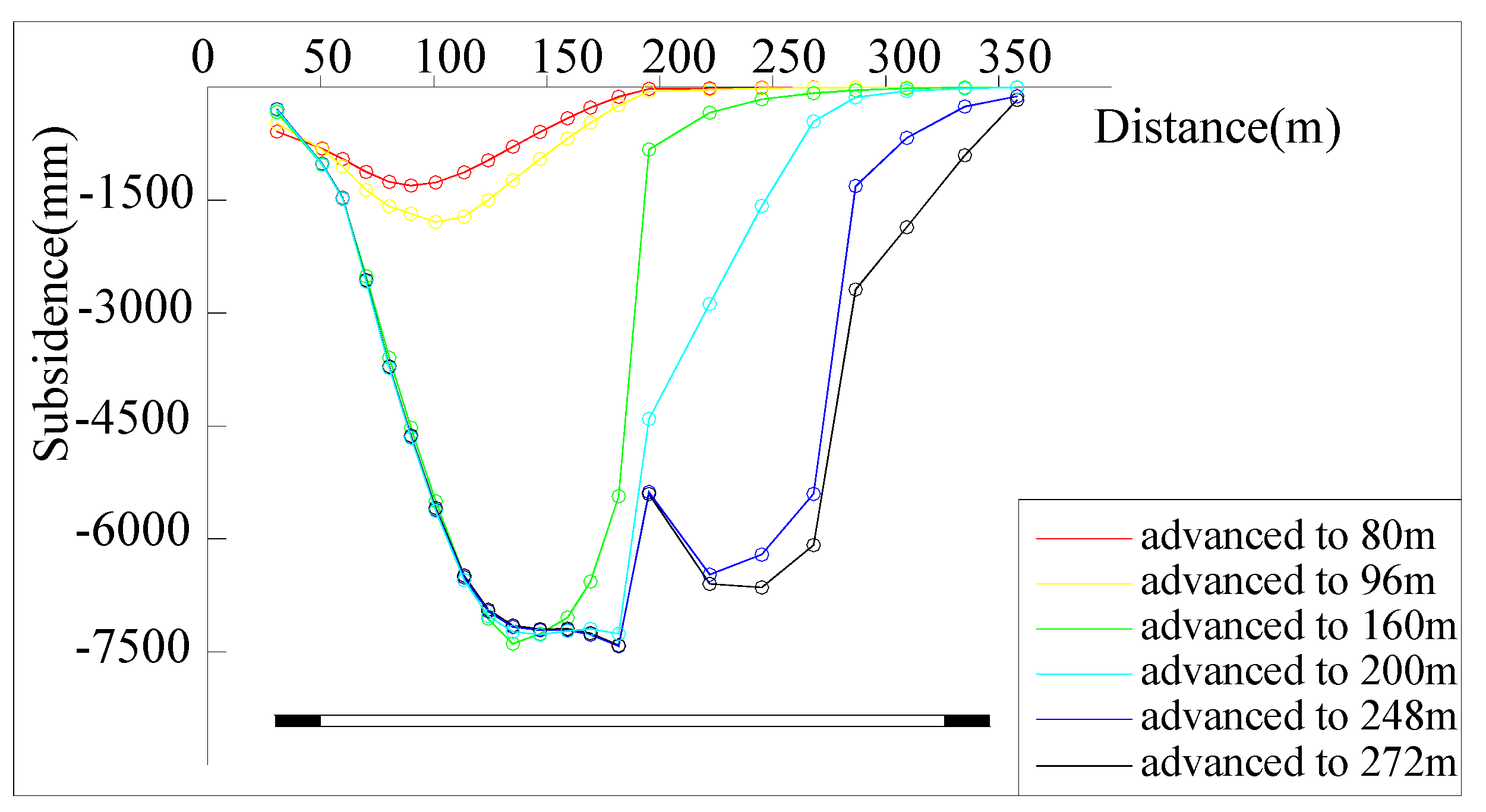
3.1. Morphological Characteristics of Overburden Caving

In the process of the working face advancing, the overlying strata will be affected by different degrees of mining, and the corresponding movement and deformation will occur. Figure 4 shows the evolution of overlying strata collapse in the process of the working face advancing.
The working face is advanced along the uphill direction from the open cut. When the coal seam is mined 80 m, the first caving occurs in the working face, and the caving height is 17.3 m. The development is terminated in the S3 strata, and the collapsed rock blocks are stacked on the coal seam floor. At this time, the mining fractures are mainly distributed in the S2 strata and are separated from the S3 strata. When the coal seam is mined 96 m, the sliding motion of the S2 rock strata due to shear failure leads to sliding instability, forming a “cutting body”. When the coal seam is mined 160 m, 200 m and 248 m, periodic caving appears in the overlying strata, periodic caving step distance is 40–48 m, the surface is accompanied by periodic cracks, mainly existing in the top of the working face and the boundary. Due to the shallow depth of the coal seam, the surface cracks eventually connect with the working face, forming a penetrating mining crack. The surface is characterized by step failure, resulting in the formation of rock pillars. According to the simulation results, it is found that, at the coal mining stage, the overburden failure is ladder-shaped, and the roof will form a “inclined step cutting body” structure, which is prone to sliding instability, as shown in Figure 4. According to the analysis, the overlying strata produced the whole inclined shear fracture in the mining process of a 22,021 working face. Under the influence of its own gravity and coal mining factors, the blocks formed after the fracture are prone to slide and cause instability of the overall structure. The blocks formed after the shear fracture of the overlying strata are called the “cutting body”. The structure formed by the interaction of the “cutting body” is the “inclined step cutting body” structure. Due to the poor bearing capacity of the structure, with the sliding instability, the overburden movement produces more load on the support. At this time, the overlying load is fully transmitted, resulting in severe pressure on the working face, and it is prone to roof fall accidents. The structure reasonably explains the phenomenon of safety accidents in shallow coal seam mining.
Real-time monitoring on the surface is conducted before the excavation. The surface subsidence during the mining process of the working face is recorded and plotted into a curve, which is shown in the diagram in Figure 5. With the enlargement of the mined-out area, the surface subsidence and influence range gradually increase. In the process of coal seam mining, the surface subsidence curve presents a “U” shape. Due to a certain slope on the surface, the curve is not symmetrical to the center of the goaf. In the early stage of working face mining, the subsidence curve was relatively flat. Then, due to the sliding and instability of the overlying rock “inclined step cutting body” structure, there are steps breaking on surface. At this time, the subsidence value of the monitoring point corresponding to the surface will increase sharply with the maximum subsidence reaching 7250 mm. According to the surface rock movement data, the measured maximum subsidence value is 7000 mm. It can be seen that the numerical simulation results are close to the actual results, indicating that the microscopic mechanical parameters of the numerical model taken in this paper are reliable and correct.

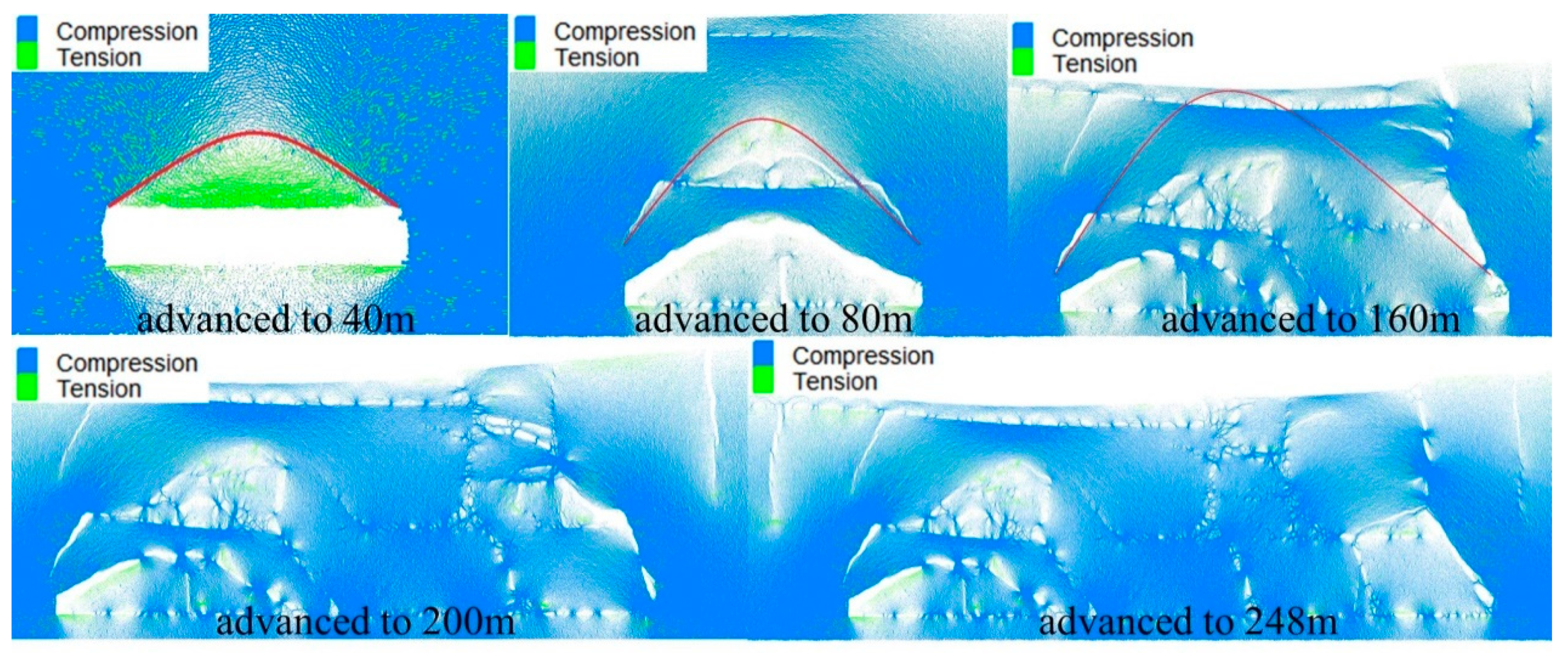
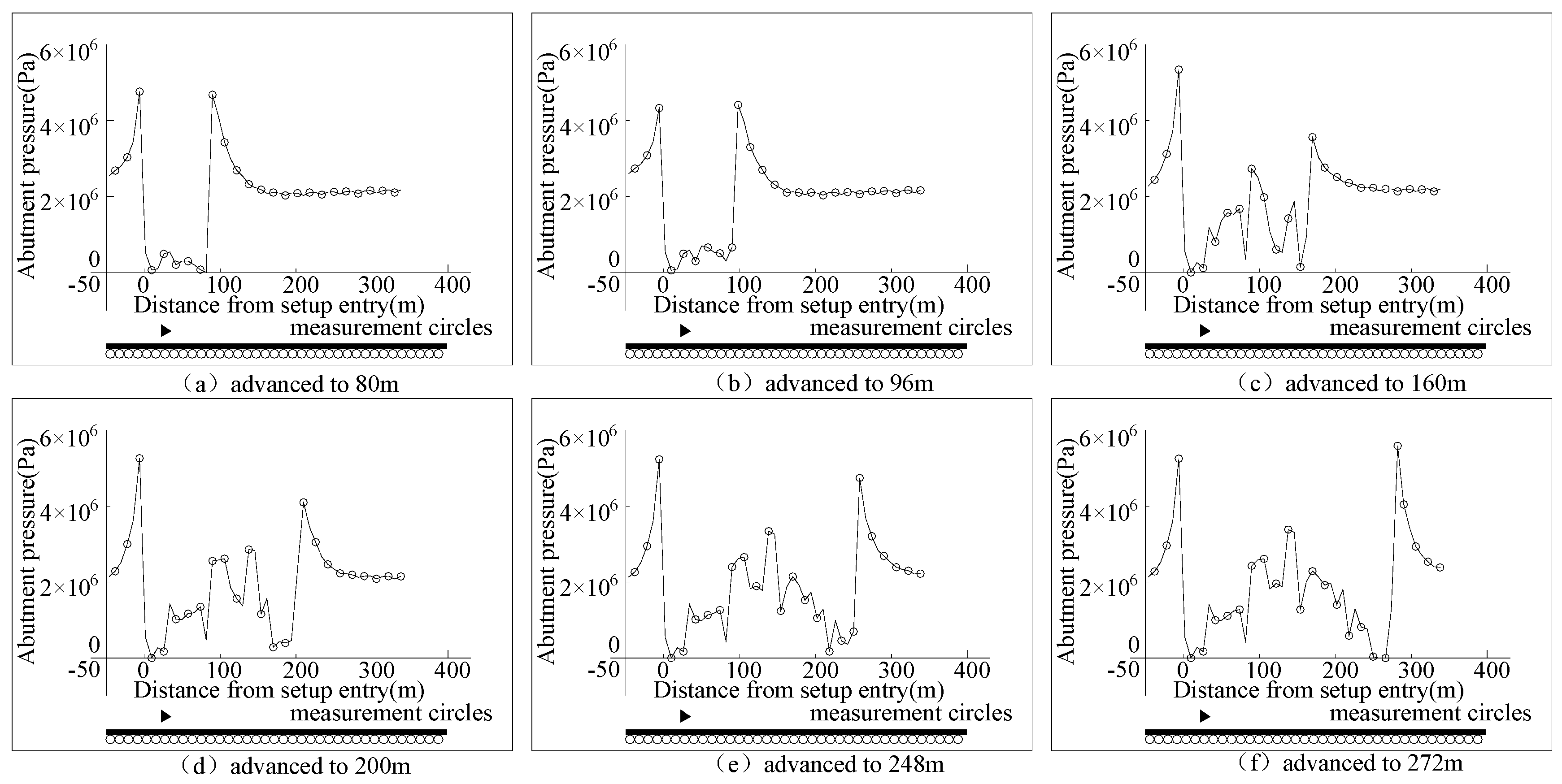
3.2. Distribution Characteristics of Force Chain

3.2.1. Analysis of Force Chain Evolution Law

Force chain is an important concept about granular materials, and is usually a linear-like chain structure formed by the continuous contact of several or dozens of particles. Relevant studies have shown that the bending deformation of the force chain is the internal cause of the deformation of granular material. In the process of numerical simulation, with the increase of external load, the force chain will deform and cause the overburden to break. Therefore, the force chain is the main form of load transfer between particles [34]. Figure 6 is the force chain evolution process in coal seam mining.
In the early stage of mining for the working face, the original balance state of the force chain was broken, and a horizontal force chain arch structure was formed above the goaf. When the coal seam is mined 40 m, the arch height is about 18 m, and the force chain arch takes the weight of the overlying strata in the goaf and makes the surrounding goaf rebalance. The front and rear arch feet of the force chain are located on the side of the coal wall of the unmined coal seam, and the force chain distribution in the unmined area of the working face is in an irregular state, as shown in Figure 6.
With the increasing range of the mined-out area, the span and height of the force chain arch increase. When the coal seam is mined 80 m, the working face collapses for the first time, and the strata are separated. The force chain shape originally located at the low level gradually develops from the arch state to the horizontal state, and a new force chain arch appears in the strata at a higher level, with an arch height of about 34 m.
When the coal seam is mined 160 m, the force chain arch develops to the surface, the height cannot be increased, and the span continues to increase. Due to exceeding its own bearing limit, the force chain arch cannot bear the load of the overlying strata, and fracture instability occurs. At this time, the working face is periodically collapsed, and the collapsed rock mass continues to fill the goaf. Due to the fracture of the force chain arch, a large number of cracks appear in the overlying strata and connect with the surface loose layer, and step subsidence begins to appear at the surface.
As the working face continues to advance, the arch force chain structure gradually disappears due to instability, and the force chain continues to develop forward. When the working face is pushed to 200 m and 248 m, the second and third periodic collapses occur respectively. At this time, at a lower position above the goaf, due to the destruction of the force chain arch, the force chain distribution is transformed into a flat state. In front of the goaf, the force chain is distributed in a vertical state.
In summary, the form of the force chain affected by mining experienced the dynamic process of force chain arch formation—force chain arch development—force chain arch failure. The force chain arch is the main force system to carry the weight of the overlying strata. When it develops to the surface, fracture instability will appear because it cannot continue to develop. At this time, the working face shows periodic collapse, the collapsed rock mass continues to fill the goaf, and step subsidence appears at the surface.
In order to further analyze the stress distribution of overlying strata in the mining process of shallow thick coal seam, the support pressure change above the coal seam is monitored by arranging the measurement circle, as shown in Figure 7. When the coal seam is mined, the increased area of abutment pressure is located in the rear of the unmined coal body and the front of the working face, and the increased area of tensile stress is located directly above the working face. With the continuous advancement of the working face, the maximum abutment pressure values in the front and rear of the goaf gradually increase. When the coal seam is mined 80 m, the working face first collapses, and the maximum abutment pressure of all monitoring points is 4.76 MPa. After that, the working face begins to collapse periodically, and the change of the supporting stress of the overlying rock above the goaf is more complex than that of the coal body. The peak value of the advanced supporting pressure shows a slowly increasing trend, and the position is always located in the front of the working face, which is consistent with the distribution law of the traditional “supporting stress” [17]. After working face mining, the maximum abutment pressure of all monitoring points is 5.58 MPa.

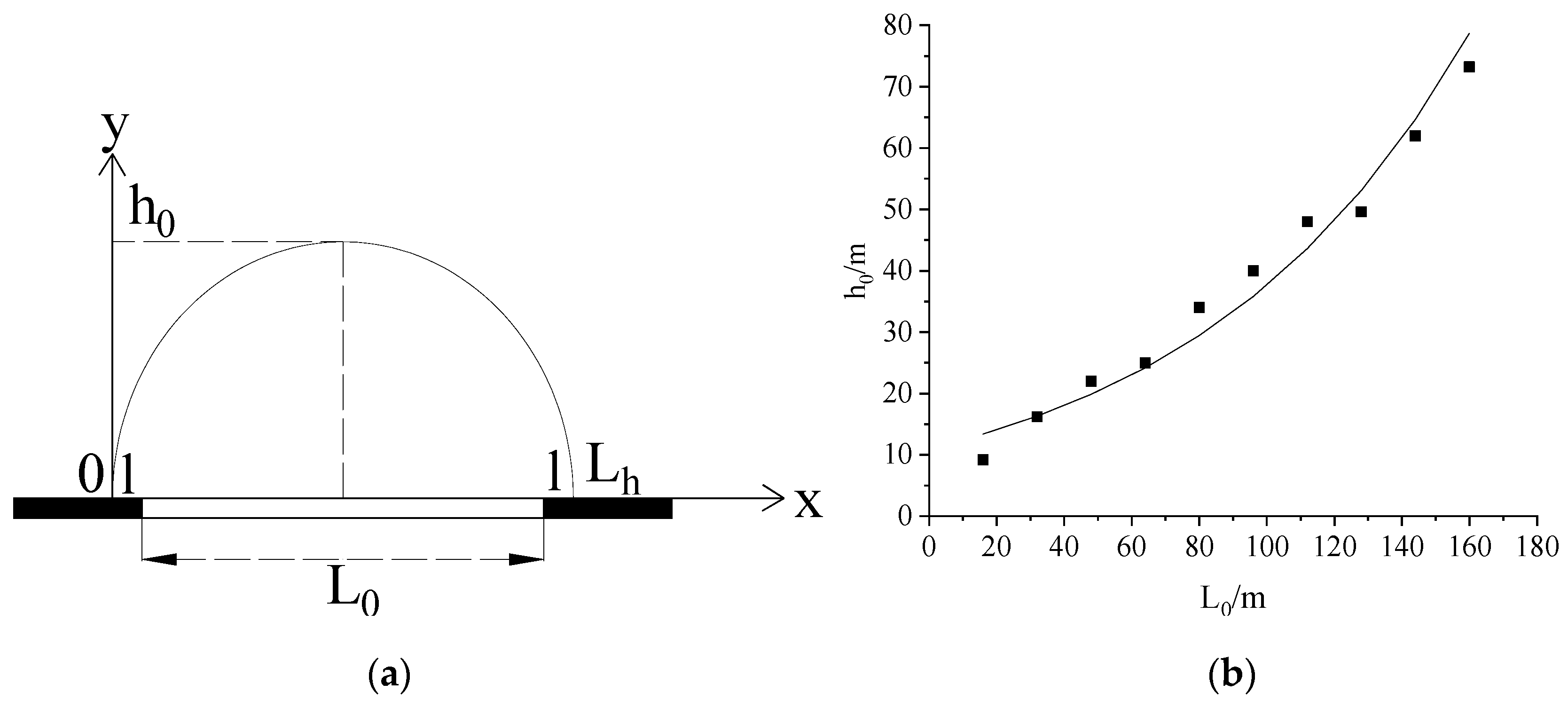
3.2.2. Establishment of Mechanical Model of Force Chain Arch

Further analysis of Figure 6 shows that, in the vicinity of the stope, with the continuous mining of the coal seam, the force chain arch continues to develop, and the height and span increase. When advancing to a certain distance, the force chain arch develops to the surface and becomes unstable due to the failure to withstand the load above. The drawing curve of the shape of the force chain arch before instability is approximately parabolic, as shown in Figure 8a. The distance between the front and rear arch feet is the horizontal axis, and the arch height is the vertical axis. The force chain arch equation can be established as follows:
y = c x ( L h x ) ,
where c is the undetermined coefficient and Lh is the distance between the front and rear arch feet. In reference, the authors equate the arch foot position before and after the force chain with the boundary of the coal pillar, and find that the peak stress point should be located at a certain distance in front of the coal wall. Therefore, the force chain arch equation is modified in this paper. According to the geometric relationship, we can obtain:
L h = L 0 + 2 l ,
where L0 is the advancing distance of the working face and l is the distance from the arch foot to the coal wall. When the coal seam is mined, the arch height of the force chain was h0, the equation satisfied ( L 0 2 + l , h 0 ) , and a substitution was obtained:
c = h 0 ( L 0 2 + l ) 2 .
The relationship between the advancing distance of the working face and the corresponding force chain arch height is shown in Figure 8b. It can be seen from the Figure that the two approximately meet the exponential relationship:
h 0 = a e b L 0 .
From Equations (11)–(14), the trajectory of the force chain arch can be written as follows:
y = a e b L 0 ( L 0 2 + l ) 2 x ( L 0 + 2 l x ) .
According to the numerical simulation results, under the geological and mining conditions a = 10.288, b = 0.013 (a, b are undetermined coefficients, related to the regional rock properties), the distance between the peak point of the support stress of the working face and the coal wall is about 10 m, so the pre-instability equation of the force chain arch is:
y = 10.288 e 0.013 L 0 ( L 0 2 + 10 ) 2 x ( L 0 + 20 x ) .
The force chain arch trajectory equation obtained above can be used as a judgment for large-scale subsidence damage occurring on the surface within the scope of the mine field when other working faces advance to a certain distance.
Taking another 22,064 working face in the same mining area as an example, the average mining depth of the working face is 100 m (that is, the final development height of the force chain arch), and the distance between the peak point of the support stress of the working face and the coal wall is about 8 m. When the coal seam is mined 175 m, the force chain arch develops to the surface, and large-scale subsidence damage begins to appear at the surface. The actual monitoring shows that, when the working face advances to 168 m, a large number of cracks appear on the surface, which is close to the calculation results. The results show that the failure of the force chain arch is the root cause of the surface step subsidence.

4. Discussion

Based on the 22,021 working face, the numerical calculation model is established by PFC, and the overburden caving form and force chain evolution law in the process of the working face advancing are analyzed. It should be noted that the research results of this paper are most suitable for mining in shallow thick coal seam. The main discussion is as follows:
(1)
Under the condition of shallow buried thick coal seam mining, there is trapezoidal damage above the goaf. When the overlying rock falls periodically, periodic cracks appear on the surface. Due to the shallow buried depth, after the end of the mining face, the surface cracks are connected with the working face to form a penetrating mining crack, and the surface subsidence value will change due to the step damage.
(2)
A large number of scholars have carried out a lot of research on the type of overburden structure, formation conditions and motion characteristics, forming the “masonry beam” [25], “step rock beam” [5] theory and analyzing its structural stability. Different from the existing results, this paper considers that the block formed by the fracture of overlying strata in a mined-out area under the condition of shallow buried thick coal seam is an inclined block, rather than a normal block. Therefore, according to the collapse morphology, it is found that the overlying rock will form an “inclined step cutting body” structure in the process of coal seam mining. Through the mechanical analysis of key blocks, it is concluded that the main factors affecting the stability of the structure are rock block size and rotation angle. Because the rock block index of a shallow coal seam is generally more than 1.0, the structure is prone to sliding instability. At the same time, the condition equation for solving the support force is provided, and the calculation results are in line with the actual support force in the mining process of the working face.
(3)
Particle matter is a complex system with internal organic connections formed by the interaction of many discrete particles. The force chain is a linear and relatively stable structure linked between particles in contact. In References [33,34], the force chain and its influence on particle flow motion were discussed. Different from the existing research, this paper links the force chain to the overburden movement, which provides a new idea for explaining the surface subsidence damage. In the mining stage of the working face, there is a force chain network structure in the overlying rock, and the force chain morphology undergoes a dynamic process of force chain arch formation—force chain arch development—force chain arch failure. When the force chain arch develops to the surface due to the failure of continuous development, fracture instability will occur. At this time, the working face will collapse periodically, and there is step sinking at the surface.
In Reference [17], the authors fitted the equation of arch height and coal seam mining distance, but it was not applied to practice and the influence of abutment pressure on the span of the force chain arch was not considered. According to the evolution law of force chains, the force chain arch curve equation is modified and applied to another working face in the same mining area. The theoretical calculation results are consistent with the actual situation, which proves that the failure of the force chain arch is the root cause of the surface step subsidence.
The highlights of this study:
(1)
In this study, for mining under the condition of a shallow buried thick coal seam, the structure of an “inclined step shear body” was proposed for the first time, and its correctness was verified by numerical simulation. The particle flow program was used for the first time to analyze the movement process of overlying strata in the stope from the structure of overlying strata and the internal mechanical state of overlying strata, and the intuitive reasons and root causes of surface step subsidence were obtained.
(2)
This study reveals the evolution process of the force chain under a shallow thick coal seam for the first time and modifies the trajectory equation before the instability of the force chain arch. The analysis shows that the distribution of the force chain is closely related to surface damage.
The limitations of this study:
Due to the large number of calculations, the surface morphology and rock stratum division are simplified, and subsidence research on the mining area under complex geological conditions will be carried out in the next step.

5. Conclusions

(1)
Under the condition of shallow buried thick coal seam mining, the overlying strata above the goaf will form an “inclined step cutting body” structure. Through mechanical analysis, the condition equation for judging the instability of the structure and the formula for solving the support force are established. According to the results of the numerical simulation, when the rock mass i1 ≤ 0.86, the structure of the “inclined step cutting body” is not prone to sliding and instability. Considering that i = 1.0~1.4 under the condition of shallow buried thick coal seam, the structure of the “inclined step cutting body” is prone to being destroyed, leading to instability. The minimum supporting force to maintain structural stability is 0.2Fn, which is in line with the actual support force in the mining process of the working face. The calculation results show that the structural instability is the intuitive reason for the severe weighting of the working face. The research results are more suitable for mining under a shallow thick coal seam. The mining depth is less than 200 m and the coal thickness is greater than 3.5 m.
(2)
In the discrete medium system of discontinuous coal rock, the force chain is the main force system for bearing the load of the overlying strata. Based on the numerical simulation results, the trajectory equation of the force chain arch is corrected. Taking the mining technical parameters of another working face in the same mining area into the formula, it can be concluded that, when the working face advances to 175 m, the force chain arch develops to the surface, and large-scale subsidence damage begins to appear at the surface. The actual monitoring found that, when the working face advances to 168 m, a large number of cracks appear on the surface, which is close to the calculation results. The theoretical calculation results and field measurements show that the instability of the force chain arch will cause a large area of collapse of the overlying rock above the goaf, and induce serious damage to the surface. The failure of the force chain arch is the root cause of the surface subsidence.
(3)
PFC simulates the movement of particles according to Newton’s second law and force-displacement law, which can intuitively see the dynamic evolution process of overburdened structure and fracture development. The results show that the particle flow theory is more suitable for studying the discontinuous deformation of stope overburdening, which is of great significance for the prediction of subsidence failure.

Author Contributions

Conceptualization, Y.Z. (Yanjun Zhang); methodology, Y.Z. (Yanjun Zhang), Y.Y. and H.D.; software, Y.Z. (Yanjun Zhang) and Y.Y.; validation, Y.Z. (Yanjun Zhang); formal analysis, Y.Z. (Yuanhao Zhu) and H.D.; investigation, Y.Z. (Yanjun Zhang) and T.W.; resources, Y.Z. (Yanjun Zhang); data curation, Y.Z. (Yanjun Zhang); writing—original draft preparation, Y.Z. (Yanjun Zhang), Y.Y. and Y.Z. (Yanjun Zhang); Writing—review & editing, Y.Z. (Yanjun Zhang) and Y.Y.; visualization, T.W.; supervision, T.W.; project administration, Y.Z. (Yanjun Zhang), Y.Y. and H.D.; funding acquisition, Y.Z. (Yanjun Zhang), Y.Y. and H.D. All authors have read and agreed to the published version of the manuscript.

Funding

This research was funded by the National Natural Science Foundation of China grant number [51574242, 51404272], the Shanxi Graduate Education Innovation Project of China grant number [2019SY126]. The APC was funded by [51574242].

Conflicts of Interest

The authors declare no conflict of interest.

References

  1. Liu, H.; Deng, K.; Lei, S.; Bian, Z.F.; Chen, D.Y. Dynamic developing law and governance standard of ground fissures caused by underground mining. J. Min. Saf. Eng. 2017, 34, 884–900. [Google Scholar]
  2. Li, J.W.; Li, X.T.; Liu, C.Y.; Wu, X.Y.; Neves, L.C. Dynamic Changes in Surface Damage Induced by High-Intensity Mining of Shallow, Thick Coal Seams in Gully Areas. Adv. Civ. Eng. 2020, 6, 1–16. [Google Scholar] [CrossRef] [Green Version]
  3. Huang, Q.X.; Zhou, J.L.; Cao, J.; Jin, J. Key Stratum Structure and Support Working Resistance of Longwall Face with Large Mining Height in the Shallow Coal Seams, China. Adv. Civ. Eng. 2020, 3, 1–14. [Google Scholar] [CrossRef]
  4. Huang, Q.X.; He, Y.P.; Cao, J. Experimental Investigation on Crack Development Characteristics in Shallow Coal Seam Mining in China. Energies 2019, 12, 1302. [Google Scholar] [CrossRef] [Green Version]
  5. Huang, Q.H.; Zhang, P.; Dong, A.J. Mathematical model of “arch beam” of thick sandy soil layer movementin shallow seam. Rock Soil Mech. 2009, 30, 2722–2726. [Google Scholar]
  6. Liu, Y.J.; Qi, Q.J.; Wang, A.H.; Jiang, B.Y. Influence of Valleys Terrain on Pressure of Fully Mechanized Working Faces in Shallow Coal Seams. Shock Vib. 2021, 2, 1–11. [Google Scholar]
  7. Wang, Z.; Li, J.; Wu, C.; Lv, W.; Zhang, J.; Wang, P.; Li, Z.; Qu, H. Study on Influence Laws of Strata Behaviors for Shallow Coal Seam Mining beneath Gully Terrain. Shock Vib. 2021, 6, 1–12. [Google Scholar]
  8. Piotr, S.; Krzysztof, T. Analytical and numerical method assessing the risk of sinkholes formation in mining areas. Int. J. Min. Sci. Technol. 2015, 25, 85–89. [Google Scholar]
  9. Barbato, J.; Hebblewhite, B.; Mitra, R.; Mills, K. Prediction of horizontal movement and strain at the surface due to longwall coal mining. Int. J. Rock Mech. Min. Sci. 2016, 84, 105–118. [Google Scholar] [CrossRef]
  10. Liu, H.; He, C.G.; Deng, K.Z.; Bian, Z.F.; Fan, H.D.; Lei, S.G.; Zhang, A.B. Analysis of forming mechanism of collapsing ground fissure caused by mining. J. Min. Saf. Eng. 2013, 30, 380–384. [Google Scholar]
  11. Marian, D.P.; Onica, I. Analysis of the Geomechanical Phenomena That Led to the Appearance of Sinkholes at the Lupeni Mine, Romania, in the Conditions of Thick Coal Seams Mining with Longwall Top Coal Caving. Sustainability 2021, 13, 6449. [Google Scholar] [CrossRef]
  12. Salmi, E.F.; Nazem, M.; Deng, K.Z.; Karakus, M. Numerical analysis of a large landslide induced by coal mining subsidence. Eng. Geol. 2017, 217, 141–152. [Google Scholar] [CrossRef]
  13. Trong, N.D.; Wu, J.H. Simulating a mining-triggered rock avalanche using DDA: A case study in Nattai North, Australia. Eng. Geol. 2019, 264, 105386. [Google Scholar]
  14. Gennes, D.P.G. Dynamics of Entangled Polymer Solutions. I. The Rouse Model. Macromolecules 1976, 9, 587–593. [Google Scholar] [CrossRef]
  15. Park, J.W.; Song, J.J. Numerical simulation of a direct shear test on a rock joint using a bonded-particle model. Int. J. Rock Mech. Min. Sci. 2009, 46, 1315–1328. [Google Scholar] [CrossRef]
  16. Le Bouil, A.; Amon, A.; Sangleboeuf, J.C.; Orain, H.; Bésuelle, P.; Viggiani, G.; Chasle, P.; Crassous, J. A biaxial apparatus for the study of heterogeneous and intermittent strains in granular materials. Granular Matter. 2014, 16, 1–8. [Google Scholar] [CrossRef]
  17. Lian, X.; Zhang, Y.; Yuan, H.; Wang, C.; Guo, J.; Liu, J. Law of Movement of Discontinuous Deformation of Strata and Ground with a Thick Loess Layer and Thin Bedrock in Long Wall Mining. Appl. Sci. 2020, 10, 2874. [Google Scholar] [CrossRef] [Green Version]
  18. Choi, S.K.; Park, J.Y.; Lee, D.H.; Lee, S.R.; Kim, Y.T.; Kwon, T.H. Assessment of barrier location effect on debris flow based on smoothed particle hydrodynamics (SPH) simulation on 3D terrains. Landslides 2021, 217–234. [Google Scholar] [CrossRef]
  19. Xu, W.J.; Xu, Q.; Liu, G.Y.; Xu, H.Y. A novel parameter inversion method for an improved DEM simulation of a river damming process by a large-scale landslide. Eng. Geol. 2021, 293, 106282. [Google Scholar] [CrossRef]
  20. Conte, E.; Pugliese, L.; Troncone, A. Post-failure analysis of the Maierato landslide using the material point method. Eng. Geol. 2019, 253, 149–159. [Google Scholar] [CrossRef]
  21. Nguyen, T.S.; Yang, K.H.; Ho, C.C.; Huang, F.C. Postfailure Characterization of Shallow Landslides Using the Material Point Method. Geofluids 2021, 10, 8860517. [Google Scholar]
  22. Troncone, A.; Pugliese, L.; Conte, E. Run-Out Simulation of a Landslide Triggered by an Increase in the Groundwater Level Using the Material Point Method. Water 2020, 12, 2817. [Google Scholar] [CrossRef]
  23. Jin, Y.F.; Yin, Z.Y.; Yuan, W.H. Simulating retrogressive slope failure using two different smoothed particle finite element methods: A comparative study. Eng. Geol. 2020, 279, 105870. [Google Scholar] [CrossRef]
  24. Zhou, Y.; Li, F.; Hai, X.G. Analysis on evolution characteristics for overburden and chain of top-coal using fully mechanized top coal caving mining. J. Min. Saf. Eng. 2018, 35, 751–755, 825. [Google Scholar]
  25. Qian, M.G.; Shi, P.W.; Xu, J.L. Mining Pressure and Strata Control; China University of Mining and Technology Press: Xuzhou, China, 2010. [Google Scholar]
  26. Huang, Q.X.; Shi, P.W.; Qian, M.G. Experiment study on the coefficients of friction and inserting of main roof block corner. Rock Soilmechanics 2000, 21, 60–63. [Google Scholar]
  27. Huang, Q.X. Studies on load-transmitting factor of thick sandy soil layer on key roof stratum in shallow seam mining. Chin. J. Geotech. Eng. 2005, 27, 672–676. [Google Scholar]
  28. Zhou, J.; Chi, Y.; Chi, Y.W.; Xu, J.P. The method of particle flow and PFC2D Code. Rock Soil Mech. 2000, 21, 271–274. [Google Scholar]
  29. Wu, Q.S.; Hu, M.B. Research Progress on Dynamic Model and Experiment of Particle Flow. Rock Soil Mech. 2002, 32, 250–258. [Google Scholar]
  30. Itasca Consulting Group Incorporated. PFC (Particle Flow Code in 2 and 3 Dimensions); Version 5.0 [User’s Manual]; Itasca Consulting Group Incorporated: Minneapolis, MN, USA, 2016. [Google Scholar]
  31. Chen, P.Y. Research progress on pfc2d simulation of crack propagation characteristics of cracked rock. J. Eng. Geol. 2018, 26, 253–264. [Google Scholar]
  32. Wang, C.; Zhang, C.; Zhao, X.; Liao, L.; Zhang, S. Dynamic structural evolution of overlying strata during shallow coal seam longwall mining. Int. J. Rock Mech. Min. Sci. 2018, 103, 20–32. [Google Scholar] [CrossRef]
  33. Lee, H.; Jeon, S. An experimental and numerical study of fracture coalescence in pre-cracked specimens under uniaxial compression. Int. J. Solids Struct. 2011, 48, 979–999. [Google Scholar] [CrossRef] [Green Version]
  34. Sun, Q.C.; Xin, H.L.; Liu, J.G.; Jin, F. Skeleton and force chain network in static granular material. Rock Soil Mech. 2009, 30, 83–87. [Google Scholar]
Figure 1. Geographical location of mine field.
Applsci 11 10276 g001
Figure 2. Structural mechanics model of inclined step-cuting body.
Applsci 11 10276 g002
Figure 3. Numerical model.
Applsci 11 10276 g003
Figure 4. Rock caving patterns at different advancing distances.
Applsci 11 10276 g004
Figure 5. Numerical simulation of subsidence curve.
Applsci 11 10276 g005
Figure 6. Evolution law of force chains.
Applsci 11 10276 g006
Figure 7. Distribution of support pressure.
Applsci 11 10276 g007
Figure 8. Curve track and height relation diagram of the force chain arch. (a) Curve track of force chain arch. (b) Arch height relationship of force chain.
Applsci 11 10276 g008
Table 1. Composition of coal seam overburden.
NumberLithologicDepth (m)Depth (m)
S4Loess layer5–1616
S3Siltstone4460
S2Mudstone3090
S1Coal898
S0Gritstone10108
Table 2. Micromechanical parameters of strata.
SymbolDescriptionLoess Layer Siltstone Mudstone Coal Gritstone
γ (KN/m3)Volume-weight17242414.225.1
R(cm)Minimum radius of particles2020202020
Rmax/RminParticle Radius Ratio1.61.61.61.61.6
E* (GPa)Effective modulus of flat joint0.4231.2413.624.2419.72
K*Rigidity ratio of flat joint22222
σ c (MPa)Average tensile strength and standard deviation of flat joints0.1/0.0251.8/0.50.8/0.20.25/0.06251.1/0.275
c (MPa)Average cohesion and standard deviation of flat joints4/120/520/510/2.520/5
Note: In other numerical models, E generally represents the elastic modulus, and K generally represents the bulkmodulus. In order to distinguish these similar symbols, this paper uses E* to represent the effective modulus of flatjoint and K* to represent the rigidity ratio of flat joint.
Publisher’s Note: MDPI stays neutral with regard to jurisdictional claims in published maps and institutional affiliations.

