
Physical Simulation of the Spectrum of Possible Electromagnetic Effects of Upward Streamer Discharges on Model Elements of Transmission Line Monitoring Systems Using Artificial Thunderstorm Cell

 ,
,
Abstract
:Featured Application
Abstract
1. Introduction
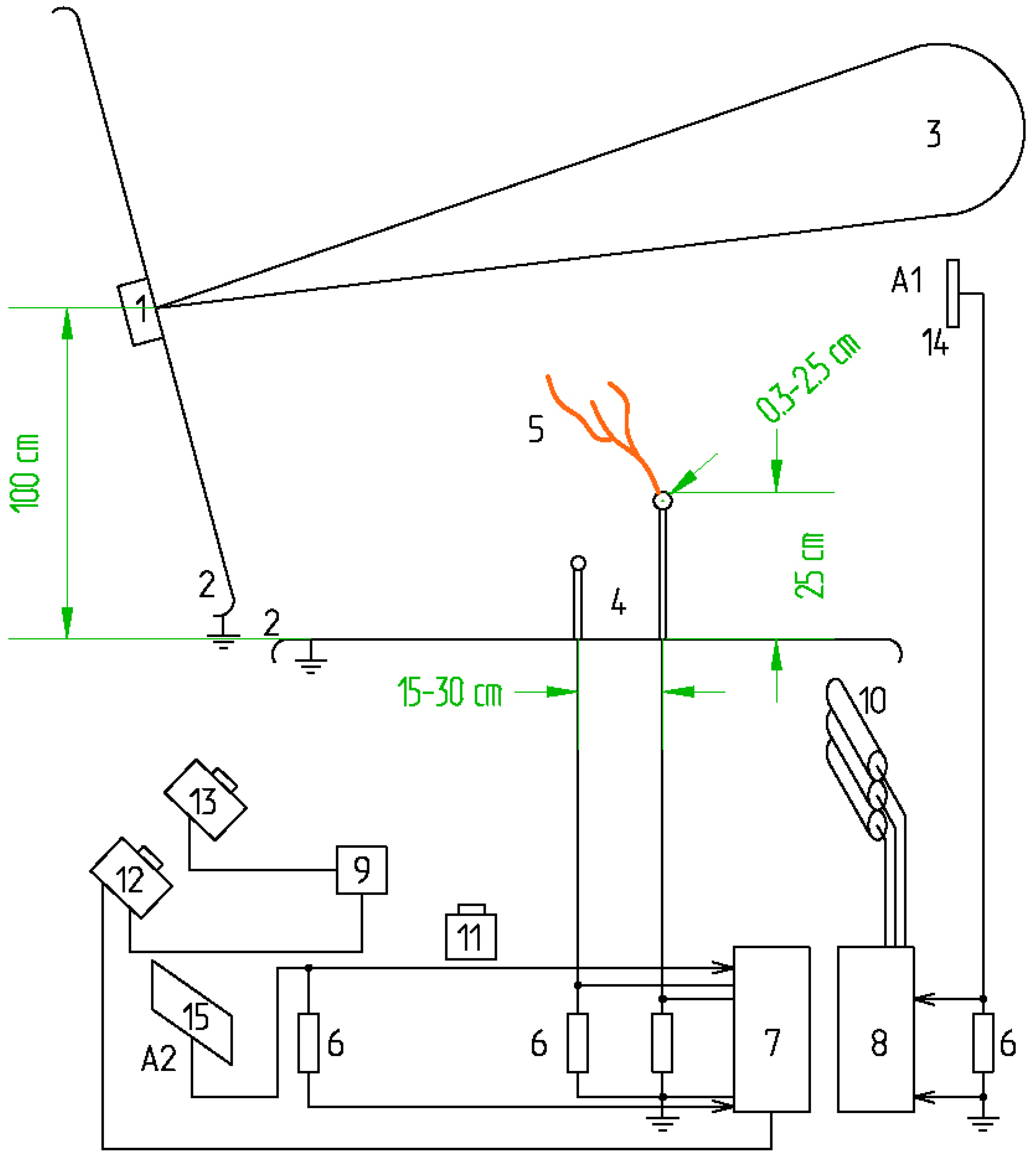
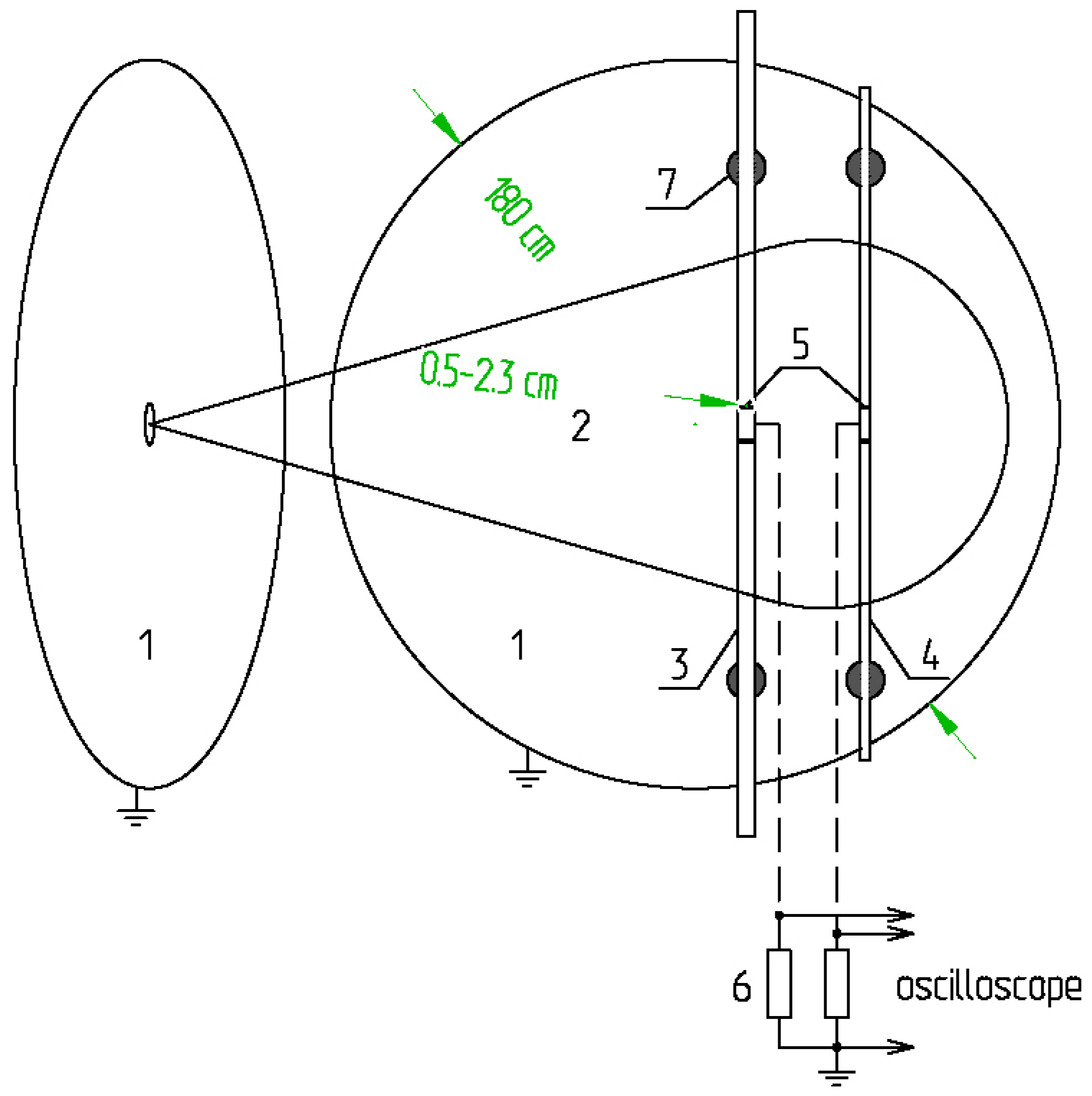
2. Experimental Schemes
3. Analysis of Results and Discussion
4. Conclusions
Author Contributions
Funding
Institutional Review Board Statement
Informed Consent Statement
Data Availability Statement
Conflicts of Interest
References
- Hu, Y.; Liu, K. Inspection and Monitoring Technologies of Transmission Lines with Remote Sensing; Academic Press: Cambridge, MA, USA, 2017. [Google Scholar]
- Li, S.; Li, J. Condition monitoring and diagnosis of power equipment: Review and prospective. High Volt. 2017, 2, 82–91. [Google Scholar] [CrossRef]
- Deng, C.-J. Challenges and Prospects of Power Transmission Line Intelligent Monitoring Technology. Am. Res. J. Comput. Sci. Inf. Technol. 2019, 4, 1–11. [Google Scholar]
- Zhirui, L.; Shengsuo, N.; Nan, J. Current Status and Development Trend of AC Transmission Line Parameter Measurement. Autom. Electr. Power Syst. 2017, 41, 181–191. [Google Scholar]
- Liu, Y.; Yin, H.; Wu, T. Transmission Line on-line Monitoring System Based on Ethernet and McWiLL. In Proceedings of the International Conference on Logistics Engineering, Management and Computer Science (LEMCS 2015), Shenyang, China, 26–28 June 2015; pp. 680–683. [Google Scholar]
- Working Group on Monitoring & Rating of Subcommittee 15.11 on Overhead Lines. Real-Time Overhead Transmission-Line Monitoring for Dynamic Rating. IEEE Trans. Power Deliv. 2016, 31, 921–927. [Google Scholar] [CrossRef]
- Xing, Z.; Cui, W.C.; Liu, R.; Zheng, Z. Design and Application of Transmission Line Intelligent Monitoring System. In Proceedings of the 2020 International Conference on Energy, Environment and Bioengineering (ICEEB 2020), Xi’an, China, 7–9 August 2020; Volume 185. [Google Scholar] [CrossRef]
- McCall, J.C.; Spillane, P.; Lindsey, K. Determining Crossing Conductor Clearance Using Line-Mounted LiDAR. In Proceedings of the CIGRE US National Committee 2015 Grid of the Future Symposium, Paris, France, 12 October 2015. [Google Scholar]
- Wydra, M.; Kubaczynski, P.; Mazur, K.; Ksiezopolski, B. Time-Aware Monitoring of Overhead Transmission Line Sag and Temperature with LoRa Communication. Energies 2019, 12, 505. [Google Scholar] [CrossRef] [Green Version]
- Chen, H.; Qian, Z.; Liu, C.; Wu, J.; Li, W.; He, X. Time-Multiplexed Self-Powered Wireless Current Sensor for Power Transmission Lines. Energies 2021, 14, 1561. [Google Scholar] [CrossRef]
- Hoole, P.R.P.; Sharip, M.R.M.; Fisher, J.; Pirapaharan, K.; Othman, A.K.H.; Julai, N.; Rufus, S.A.; Sahrani, S.; Hoole, S.R.H. Lightning Protection of Aircraft, Power Systems and Houses Containing IT Network Electronics. J. Telecommun. Electron. Comput. Eng. 2017, 9, 3–10. [Google Scholar]
- Ahmad, M.R.; Esa, M.R.M.; Cooray, V.; Dutkiewicz, E. Interference from cloud-to-ground and cloud flashes in wireless communication system. Electr. Power Syst. Res. 2014, 113, 237–246. [Google Scholar] [CrossRef]
- Borisov, R.K.; Zhulikov, S.S.; Koshelev, M.A.; Maksimov, B.K.; Mirzabekyan, G.Z.; Turchaninova, Y.S.; Khrenov, S.I. A Computer-aided design system for protecting substations and overhead power lines from lightning. Russ. Electr. Eng. 2019, 90, 86–91. [Google Scholar] [CrossRef]
- Cooray, V. Lightning Electromagnetics; IET Publishing: London, UK, 2012. [Google Scholar]
- Cooray, V.; Cooray, G. Electromagnetic fields of accelerating charges: Applications in lightning protection. Electr. Power Syst. Res. 2017, 145, 234–247. [Google Scholar] [CrossRef]
- Nag, A.; Murphy, M.J.; Schulz, W.; Cummins, K.L. Lightning location systems: Insights on characteristics and validation technique. Earth Space Sci. 2015, 2, 65–93. [Google Scholar] [CrossRef]
- Chen, M.; Du, Y.; Burnett, J.; Dong, W. The electromagnetic radiation from lightning in the interval of 10 kHz to 100 MHz. In Proceedings of the 12th International Conference on Atmospheric Electricity, Versailles, France, 9–14 June 2003. [Google Scholar]
- Makela, J. Electromagnetic Signatures of Lightning near the HF Frequency Band; Finnish Meteorological Institute: Helsinki, Finland, 2009. [Google Scholar]
- Dong, W.; Liu, H. Observation of compact intracloud discharges using VHF broadband interferometer. In Proceedings of the 2012 International Conference on Lightning Protection (ICLP), Vienna, Austria, 2–7 September 2012. [Google Scholar]
- Rakov, V.A. Electromagnetic Methods of Lightning Detection. Surv. Geophys. 2013, 34, 731–753. [Google Scholar] [CrossRef]
- Temnikov, A.G. Using of artificial clouds of charged water aerosol for investigations of physics of lightning and lightning protection. In Proceedings of the 2012 International Conference on Lightning Protection (ICLP), Vienna, Austria, 2–7 September 2012. [Google Scholar] [CrossRef]
- Bazelyan, E.M.; Raizer, Y.P. Lightning Physics and Lightning Protection; IoP Publishing: Bristol, UK; New York, NY, USA, 2000. [Google Scholar]
- Esa, M.R.M.; Ahmad, M.R.; Cooray, V. Wavelet analysis of the first electric field pulse of lightning flashes in Sweden. J. Atmos. Res. 2014, 138, 253–267. [Google Scholar] [CrossRef]
- Temnikov, A.G.; Chernensky, L.L.; Belova, O.S.; Orlov, A.V.; Zimin, A.S. Spectral characteristics of discharges from artificial charged aerosol cloud. In Proceedings of the 2014 International Conference on Lightning Protection (ICLP), Shanghai, China, 11–18 October 2014. [Google Scholar]
- Cooray, V.; Cooray, G. The Electromagnetic Fields of an Accelerating Charge: Applications in Lightning Return-Stroke Models. IEEE Trans. Electromagn. Compat. 2010, 52, 944–955. [Google Scholar] [CrossRef]
- Cooray, V.V.; Cooray, G. Electromagnetic radiation field of an electron avalanche. Atmos. Res. 2012, 117, 18–27. [Google Scholar] [CrossRef]
- Shi, F.; Liu, N.; Dwyer, J.R.; Ihaddadene, K.M.A. VHF and UHF electromagnetic radiation produced by streamers in lightning. Geophys. Res. Lett. 2019, 46, 443–451. [Google Scholar] [CrossRef] [Green Version]
- Gushchin, M.E.; Korobkov, S.V.; Zudin, I.Y.; Nikolenko, A.S.; Mikryukov, P.A.; Syssoev, V.S.; Sukharevsky, D.I.; Orlov, A.I.; Naumova, M.Y.; Kuznetsov, Y.A.; et al. Nanosecond electromagnetic pulses generated by electric discharges: Observation with clouds of charged water droplets and implications for lightning. Geophys. Res. Lett. 2021, 48, e2020GL092108. [Google Scholar] [CrossRef]
- Judge, M.A.; Manzoor, A.; Ahmed, F.; Kazmi, S.; Khan, Z.A.; Qasim, U.; Javaid, N. Monitoring of Power Transmission Lines Through Wireless Sensor Networks in Smart Grid. In Proceedings of the 11th International Conference on Innovative Mobile and Internet Services in Ubiquitous Computing, Torino, Italy, 28–30 June 2017. [Google Scholar]


| Amplification Coefficient | Group I | Group II | Group III |
|---|---|---|---|
| Current amplitude, A | 8.45 | 5.11 | 3.26 |
| Maximal current rise velocity, A/ns | 0.13 | 0.17 | 0.14 |
| Impulse duration, µs | 2.65 | 5.24 | 2.98 |
| Flowing charge, µC | 4.38 | 4.17 | 1.96 |
| Amplification Coefficient | Group I | Group II | Group III |
|---|---|---|---|
| Current amplitude, A | 8.89 | 3.04 | 2.19 |
| Maximal current rise velocity, A/ns | 0.10 | 0.13 | 0.12 |
| Impulse duration, µs | 4.12 | 7.08 | 9.23 |
| Flowing charge, µC | 6.54 | 5.09 | 4.12 |
| Source of Effect | Streamer Corona (Rod Model Element) | Streamer Corona (Elongated Model Element) | ||
|---|---|---|---|---|
| Amplification Coefficient | Signal Amplitude, A | Signal Duration, µs | Signal Amplitude, A | Signal Duration, µs |
| Group I | 0.94 | 1.06 | 1.18 | 1.12 |
| Group II | 1.36 | 0.31 | 1.41 | 0.52 |
| Group III | 1.02 | 0.69 | 1.22 | 0.97 |
| Amplification Coefficient | Group I | Group II | Group III |
|---|---|---|---|
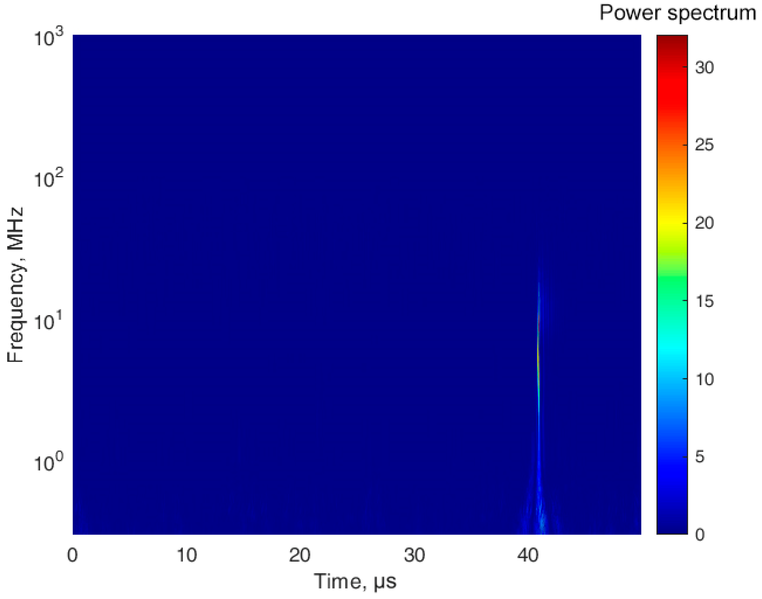
| Upper level of the characteristic frequency, MHz | 9.9 | 13.2 | 83.5 |
| Frequency of the maximal intensity, MHz | 0.9 | 1.1 | 5.8 |
| Maximal intensity, A2 | 2300 | 900 | 450 |
| Amplification Coefficient | Group I | Group II | Group III |
|---|---|---|---|
| Upper level of the characteristic frequency, MHz | 6.8 | 5.2 | 9.5 |
| Frequency of the maximal intensity, MHz | 0.5 | 0.4 | 1.8 |
| Maximal intensity, A2 | 3600 | 800 | 200 |
| Amplification Coefficient | Group I | Group II | Group III |
|---|---|---|---|
| Upper level of the characteristic frequency, MHz | 111 | 795 | 397 |
| Frequency of the maximal intensity, MHz | 10 | 76 | 27 |
| Maximal intensity, A2 | 10 | 14 | 9 |
| Amplification Coefficient | Group I | Group II | Group III |
|---|---|---|---|
| Upper level of the characteristic frequency, MHz | 123 | 809 | 528 |
| Frequency of the maximal intensity, MHz | 8 | 68 | 18 |
| Maximal intensity, A2 | 12 | 10 | 9 |
Publisher’s Note: MDPI stays neutral with regard to jurisdictional claims in published maps and institutional affiliations. |
© 2021 by the authors. Licensee MDPI, Basel, Switzerland. This article is an open access article distributed under the terms and conditions of the Creative Commons Attribution (CC BY) license (https://creativecommons.org/licenses/by/4.0/).
Share and Cite
Lysov, N.; Temnikov, A.; Chernensky, L.; Orlov, A.; Belova, O.; Kivshar, T.; Kovalev, D.; Voevodin, V. Physical Simulation of the Spectrum of Possible Electromagnetic Effects of Upward Streamer Discharges on Model Elements of Transmission Line Monitoring Systems Using Artificial Thunderstorm Cell. Appl. Sci. 2021, 11, 8723. https://doi.org/10.3390/app11188723
Lysov N, Temnikov A, Chernensky L, Orlov A, Belova O, Kivshar T, Kovalev D, Voevodin V. Physical Simulation of the Spectrum of Possible Electromagnetic Effects of Upward Streamer Discharges on Model Elements of Transmission Line Monitoring Systems Using Artificial Thunderstorm Cell. Applied Sciences. 2021; 11(18):8723. https://doi.org/10.3390/app11188723
Chicago/Turabian StyleLysov, Nikolay, Alexander Temnikov, Leonid Chernensky, Alexander Orlov, Olga Belova, Tatiana Kivshar, Dmitry Kovalev, and Vadim Voevodin. 2021. "Physical Simulation of the Spectrum of Possible Electromagnetic Effects of Upward Streamer Discharges on Model Elements of Transmission Line Monitoring Systems Using Artificial Thunderstorm Cell" Applied Sciences 11, no. 18: 8723. https://doi.org/10.3390/app11188723
APA StyleLysov, N., Temnikov, A., Chernensky, L., Orlov, A., Belova, O., Kivshar, T., Kovalev, D., & Voevodin, V. (2021). Physical Simulation of the Spectrum of Possible Electromagnetic Effects of Upward Streamer Discharges on Model Elements of Transmission Line Monitoring Systems Using Artificial Thunderstorm Cell. Applied Sciences, 11(18), 8723. https://doi.org/10.3390/app11188723