Article

Reinforced Concrete Beams Retrofitted with External CFRP Strips towards Enhancing the Shear Capacity

by
George C. Manos
* and
Konstantinos B. Katakalos
Laboratory of Strength of Materials and Structures, Aristotle University, 54006 Thessaloniki, Greece
*
Author to whom correspondence should be addressed.
Appl. Sci. 2021, 11(17), 7952; https://doi.org/10.3390/app11177952
Submission received: 21 July 2021 / Revised: 20 August 2021 / Accepted: 23 August 2021 / Published: 28 August 2021
(This article belongs to the Special Issue Seismic Assessment and Design of Structures)

Abstract

:
The practical difficulties in upgrading the structural performance of existing reinforced concrete (RC) structures is discussed, when retrofitting structural members by conventional RC jacketing. The use of retrofitting schemes employing externally applied fiber reinforcing polymer (FRP) strips attracted considerable research attention as a preferable alternative. Such retrofitting FRP schemes aiming to upgrade the shear capacity of existing RC beams have been examined in many published works employing such externally applied FRP shear reinforcing schemes without confronting the practical difficulties arising from the presence of the RC slab. Anchoring external CFRP strips aiming to shear upgrade, which is the focus here, overrides this difficulty. It is shown that effective anchoring, using either mechanical anchors such as the ones devised by the authors or CFRP anchor ropes produced by the industry, can effectively upgrade the shear capacity of an RC T-beam under-designed in shear to the desired level. A novel laboratory test set-up, devised by the authors, can be utilized to quantify the tensile capacity of CFRP stirrups with or without anchors, that can be of practical use. The predicted, according to design guidelines, upgraded shear capacity of the tested prototype RC T-beam, employing the used shear retrofitting schemes, under-estimates the measured shear capacity by 58%. This conservatism can counter-balance uncertainties arising from in situ conditions in constructing the various parts of such a shear retrofitting scheme.

1. Introduction

In many European countries, a large proportion of the building stock constructed after the end of WWII is multi-story reinforced concrete (RC) structural formations composed of slabs, beams, columns, and shear walls cast in place. The ease offered by this type of construction and the relatively low cost compared to alternative structural forms led to RC building becoming dominant in many countries. Unfortunately, a large number of these buildings were designed and constructed to resist low levels of seismic actions as shown by the development of serious structural damage when subjected to strong earthquake excitations [1]. During the last thirty years, a large volume of research on the seismic response of RC structural components and structural systems has provided a strong basis for upgrading the seismic provisions of RC structural design. Therefore, RC buildings that are currently designed and constructed according to such upgraded seismic code provisions can meet future earthquake excitations, as defined from probabilistic studies for each country, developing controlled structural damage that ensures that such RC buildings will not collapse. Moreover, the structural damage which will develop for the “design” earthquake is repairable. In this way, upgraded design seismic codes safeguard against the loss of life as well as against excessive repair costs for contemporary RC buildings. In contrast, old existing buildings are quite vulnerable to severe structural damage for such “design” earthquakes that could lead to collapse and the loss of life, as was the case during many strong past earthquakes around the world. Confronted with such a seismic risk, research efforts have focused on devising retrofitting techniques capable of upgrading the seismic resistance of such relatively “weak” RC structural formations. This was a difficult task because, whereas reinforced concrete construction offers very substantial flexibility when cast in place, it offers no such flexibility when it is hardened. Therefore, it is quite difficult to introduce any alterations or additions to the structural elements themselves or to the structural system as a whole. A typical retrofitting technique devised for strengthening such “weak” RC structures is to upgrade the capacity of selected critical structural elements of the structural system (e.g., weak columns) with RC jackets, providing in this way the required upgrade in strength and ductility (Figure 1a,b).
A well-known construction technique for strengthening existing reinforced concrete (RC) structural elements is to apply such RC jacketing surrounding the old structural elements with these new RC jackets. RC jackets are constructed using concrete of high bond strength and low shrinkage characteristics together with additional steel reinforcement and occasionally fiber-reinforced polymer composites. A variety of techniques have been investigated in the past to strengthening under-designed RC beams, RC columns, and RC joints employing such RC jacketing techniques. Published research [2,3,4,5,6,7,8,9,10,11] has shown that such external RC jacketing improves both the flexural and shear capacity, increases stiffness and ductility together, and provides for higher axial load capacity to under-designed structural members than prior to such RC jacketing. Code provisions [12] include guidelines for the design of RC jackets. RC jacketing was utilized in the past either by strengthening structural members being damaged after a strong intensity earthquake sequence or as a preventing measure for “weak” structures due to the outcome of a relevant inspection prior to an earthquake. Such RC jacketing during the last decades has been the most favorable choice for structural engineers in seismic-prone areas.
Figure 1. (a) RC jacket of columns employing shotcrete (gunite). (b) RC jacket of column and beam at the region of their joints employing shotcrete (gunite) [13].
Applsci 11 07952 g001
However, there are also certain difficulties in employing such RC jacketing techniques. It requires specialized in situ labor and equipment; it also requires perforating the floor RC slab, by partially breaking structural elements in order to place the needed additional steel reinforcement, either longitudinal or transverse steel reinforcement. Moreover, employing such RC jacketing techniques increases the dimensions of the upgraded structural members, resulting in an increase in their stiffness and their dead load. This may not be always desirable. At the same time, such RC jackets result in a decrease in the available internal free space or applying RC jackets may face prohibitions in the external space of the structural system from adjacent buildings. The increase in mass and stiffness, resulting from RC jacketing, may change the dynamic characteristics of the whole structural system and may also cause, in some cases, undesirably increased demands at specific structural elements.
Such RC jacketing of critical structural elements can be combined, when possible, with additions to a structural system of extra shear walls along its height in proper locations. This combination can reduce excessive displacement response in a way that the demands to the critical elements are met with the corresponding capacities [13]. This retrofit concept is quite effective; however, the construction of such jackets represents a degree of practical difficulties and response issues, as mentioned before.
During the last decades, alternative retrofitting techniques were developed aiming to provide practical solutions to the in situ RC jacketing difficulties for the various RC structural elements [14,15,16,17,18,19,20,21]. Obviously, apart from the structural elements themselves, the more difficult regions for effectively retrofitting an existing RC structure are the critical areas of the structural member connections (joints) as well as the connections with the foundation. Both, the structural connections and the foundation are very critical areas that require special consideration in both identifying the nature of the probable structural damage as well as proposing countermeasures. The main flexural structural damage in slabs and beams develops in the areas of maximum bending moments. For the beams, this usually develops near the joints with the columns and shear walls where large bending moments are expected to arise due to the seismic loads. Similarly, at the ends of the beams are areas of large shear forces from the combination of earthquake forces with the dead and live loads; these will cause the appearance of shear damage in the form of diagonal cracks. The presence of large bending moments mainly from the seismic loads together with large axial forces will cause the formation of flexural damage at the top and the toe of columns, whereas the presence of shear forces from the seismic loads together with axial forces will lead to the formation of shear damage at the columns, a very dangerous form of damage (see Figure 2a,b). The presence of large shear forces from seismic loads, together with relatively low-level axial forces, will lead to the development of another dangerous form of shear damage in the shear walls (see Figure 3b), whereas the presence of short columns will lead to the development of large shear forces from seismic loads and the development again of shear damage, as shown in Figure 3a.
Alternative retrofitting techniques to RC jacketing have been developed, which employ fiber-reinforced polymers (FRP) attached externally with special organic resins or inorganic matrices to weak structural elements. This external application has in some cases specific practical advantages when the resulting structural performance is upgraded in the desired way [22,23,24,25,26,27,28,29,30,31,32,33,34]. It can be applied to various structural elements of an existing RC structure with a varying degree of effectiveness and difficulty. Thus, such a retrofit is able to easily upgrade the flexural capacity of slabs as the demands are mainly flexural. The same also applies to the flexural upgrade of RC beams for gravitational loads. The shear upgrade presents certain difficulties that are discussed within the rest of the sections of this study. Moreover, the flexural or shear upgrade of beams or columns for seismic loading is more difficult as the regions to be retrofitted are near and include the RC column-to-beam joints. For the RC columns, the flexural upgrade is again quite difficult as the regions to be retrofitted are the ones where the columns are joined with the foundation or with the beam-to-column joints. Alternatively, the shear and the compression capacity of RC columns can be effectively upgraded by externally applied CFRP close hoop strips. A large volume of research has been published utilizing strips made by FRP systems based on epoxy resins as well as high-strength steel fibers (known as SRG or SRP) with either cementitious grouts (SRG) or with organic resins (SFRP) by several researchers [14,15,16,17,18,19,20,21,22,23,24,25,26,27,28,29,30,31,32,33,34,35,36,37,38,39,40,41,42,43]. A typical mode of failure is reported to be the delamination of these FRP strips [35,36,37]. Using FRP strips based on steel wires is relatively limited when compared to the strips based on carbon fibers (CFRP).
This study focuses on the specific problem of RC T-beams which are under-designed in shear. This is a relatively common problem that is due to outdated seismic code provisions with relatively low seismic force levels used in the past, which resulted in relatively low shear force demands for such RC beams in multi-story RC buildings. According to such an outdated seismic design, the shear demands for T-beams were resulting from the combinations including dead and live load and they were met by relatively light transverse reinforcing with open hoop steel stirrups. Instead, current seismic codes result in much larger shear force demands than before at regions where such beams join the columns. In addition, they require that the transverse reinforcement consists of closed hoop steel stirrups. Therefore, it is necessary to strengthen such under-designed RC T-beams deficient in shear capacity. Figure 1b depicts a retrofitting scheme whereby such shear capacity upgrade is carried out by constructing an RC jacket employing extra closed hoop stirrups narrowly spaced. Such a scheme is relatively difficult because it requires the partial breaking of the slab in order to place the closed hoop stirrups and then cast the RC jacket. A relatively simple alternative is to try to attach externally, on the web of such RC T-beam, strips of fiber-reinforced polymers (FRP) in the form of stirrups bonding them to the concrete surface with special epoxy resins. However, even in this case, the main difficulty is to try to add closed hoop FRP stirrups. A large number of experimental investigations were performed with rectangular beam specimens which did not include the slab. In this case, the absence of the slab allows the externally attached FRP strips to have the form of closed hoop stirrups. However, in the vast majority of multistory RC buildings, the slabs are cast in unison with the supporting beams, thus forming typical T-beam structural elements; this does not allow easy passing of such FRP strips in order to form the closed hoop stirrups that are required in order to bring the shear capacity to meet the demands posed by the upgraded seismic design. It was demonstrated that applying open hoop FRP strips, thus avoiding confrontation with breaking the slab, leads to limited shear upgrade because these open hoop FRP stirrups suffer from premature debonding, thus being completely neutralized [35,36,37]. This is presented and discussed in Section 2, Section 3 and Section 4. In Figure 4 an RC T-beam is shown schematically provided with external FRP reinforcement in order to increase its flexural and shear capacity. The positive bending moment capacity increase, as shown in Figure 4, is enhanced by FRP strips bonded at the bottom side of this T-beam with an FRP strip of one or multiple layers (indicated with red color) having as width the width of the bottom side of this T-beam. For negative bending moment capacity increase, the FRP strip should be bonded alternatively at the top side of this T-beam. In this case, this becomes relatively easy because the FRP strip width can be much wider than that bonded at the bottom side. This externally bonded CFRP strip will function in the same way as the internal longitudinal steel reinforcement developing tensile axial forces. The shear capacity is similarly enhanced by the transverse shear FRP open hoop strips (indicated with blue color) bonded externally; they will also develop axial forces resisting in this way the shear force demand after the formation of the diagonal shear cracks through the concrete volume. They will function in the same way as steel shear reinforcement placed internally in the form of steel stirrups.
For either flexural or shear retrofitting utilizing externally bonded FRP strips, it is critical to investigate the capacity of the relevant bond surfaces which will be called to transfer the axial forces that develop in these FRP strips in each case. When the level of these axial tensile forces exceeds the corresponding bond capacity the debonding mode of failure appears rendering the relevant FRP reinforcement completely ineffective. This represents a serious limitation in applying such external FRP retrofitting either for flexural or shear upgrading. One effective way towards this objective has been to provide various practical schemes of anchoring that combined with the FRP strips can transfer the desired level of axial force beyond the limit posed by the relevant bonding surface as indicated in Figure 4. This has been the focus of the research reported here.
In order to confront the unsatisfactory performance due to the debonding mode of failure various anchoring schemes have been devised [44,45,46,47,48,49,50,51,52,53,54,55,56,57]. Tanarslan et al. [44] reported on the performance of RC shear deficient T-beams strengthened with carbon fiber reinforced polymers (CFRP) systems with and without mechanical anchoring in several different configurations tested under cyclic loading conditions. Manos et al. [45,46,47,48,49,50,51,52,53], as well as Katakalos et al. [54], used either CFRP or SFRP for shear strengthening. The authors of this work have devised and tested such anchoring schemes [48] which combined with externally applied FRP strips can provide the required substantial shear upgrade of RC T-beams, deficient in shear, as is presented in what follows. Moreover, a number of alternative anchoring devices to be used in shear strengthening schemes together with externally applied FRP strips are also presented and discussed. All these anchoring schemes together with external FRP strips can form equivalent closed hoop stirrups which can provide the required upgrade in shear strength for such deficient RC T-beams. In the following sections, the force transfer mechanism that is mobilized for open hoop CFRP strips with or without anchoring devices, used as transverse shear reinforcement, is presented and discussed. This is carried out initially utilizing a novel experimental set-up employing small-length “unit T-beam” specimens hosting such CFRP strips (Section 2 and Section 3). By comparing the obtained experimental results, the capacity of such CFRP strips, with or without anchoring devices, can be demonstrated. Moreover, the various failure modes involved in these transfer force mechanisms and their corresponding bearing capacity can be studied in some depth. These tested novel anchoring schemes have been devised by the authors (Patent No: EP2336455-(A1), 2011 [48]) and by the industry [52]. Both of these anchoring schemes try to tackle in an efficient and practical way the difficulty posed by the presence of the RC slab as part of the RC T-beam cross-section, as previously outlined. After studying the force transfer mechanism through the relatively small-length “unit T-beams”, the capability and effectiveness of such CFRP strips as transverse shear reinforcement, with or without anchoring devices, is demonstrated by applying the same anchoring schemes to an RC T-beam of prototype dimensions being subjected to appropriate laboratory testing as is described in Section 2 and Section 4. This “unit T-beam” and prototype T-beam experimental sequence is presented in a combined way within the present manuscript. In this way, the effectiveness of such a shear upgrade of under-designed RC T-beams is clearly demonstrated in a stepwise combined and documented way. Such a procedure has an additional practical significance because it can be also utilized for similar alternative retrofitting schemes.

2. Materials and Methods

In order to check the ability of such equivalent closed hoop stirrup schemes to upgrade the shear capacity RC T-beam structural elements, specimens of prototype dimensions are constructed and tested in the laboratory. These specimens are deliberately designed to be deficient in shear from the beginning, as is shown by the reinforcing details in Figure 5a,b. Figure 5c depicts the way such a specimen is supported and loaded with a loading arrangement known as four-point flexure, whereby the load is gradually increased monotonically until each specimen reaches its limit state. As can be seen in Figure 5a–c, such a “prototype RC T-beam” specimen is provided with sufficient top and bottom longitudinal steel reinforcement (three reinforcing steel bars of 20 mm diameter each) to provide considerable flexural capacity. In terms of geometry, support conditions, loading and longitudinal, or transverse reinforcing this prototype T-beam is symmetric along a vertical axis going through its mid-span. Three distinct regions can be seen along the specimen’s length with respect to its shear reinforcement. At the very far left and right ends, the transverse reinforcement consists of narrow spaced (every 15 mm) steel close hoop stirrups of 8mm diameter. This is done in order to prohibit any shear failure at these regions hosting the supports as well as to provide sufficient confinement in order to enhance the bond strength of the longitudinal reinforcement in this region. Next, there is a 900 mm long central region where the steel close hoop stirrups of 8 mm diameter are spaced every 70 mm. This central region of the specimen is not required to resist any shear because of the employed loading; however, the used stirrups can enhance the flexural capacity by providing confinement to the compressive zone as well as prohibiting, up to a degree, of the buckling of the longitudinal reinforcement at the compressive tope zone because of the development of large bending moments at this region.
Finally, there are two regions between the supports and the central region that are left without any internal shear reinforcement in terms of steel stirrups (east and west parts). These two regions develop under the employed loading large shear demands. Therefore, it is expected that because of this intentional shear deficiency the prototype RC T-beam in its virgin state will fail in shear in these regions. In this way, in the initial loading stage, this represents the initial control stage whereby the shear resistance is provided only by the concrete volume. Next, during three distinct loading stages corresponding to three distinct retrofitting schemes (see Section 2.2), these regions are provided with an externally applied specific shear reinforcing scheme. Each of these three distinct retrofitting schemes employs either open hoop or equivalent closed hoop FRP strips; the measured shear capacity during each of these three distinct retrofitting stages is compared to the corresponding capacity of the control virgin stage. In this way, the ability of each retrofit to upgrade the shear resistance is demonstrated. The results of the observed performance of this prototype RC T-beam, without or with a shear strength upgrade, are presented in Section 4. The prototype RC T-beam as well as the “unit T-beams”, described in Section 2.1, were built with the same concrete (the concrete compressive strength is listed in Table 1), reinforcing bars (typical tensile test shown in Figure 6a), and carbon FRP strips (typical tensile test shown in Figure 6b). From a series of laboratory tests, the compressive strength of the concrete was found equal to fck = 19.94 MPa, the yield and ultimate strength of the longitudinal reinforcing bars were found equal to 524.6 MPa and 683 MPa, whereas the ultimate strain of the CFRP material was found equal to 0.015 for Young’s modulus approximately equal to 260 GPa which is in agreement with the value given by the manufacturers.

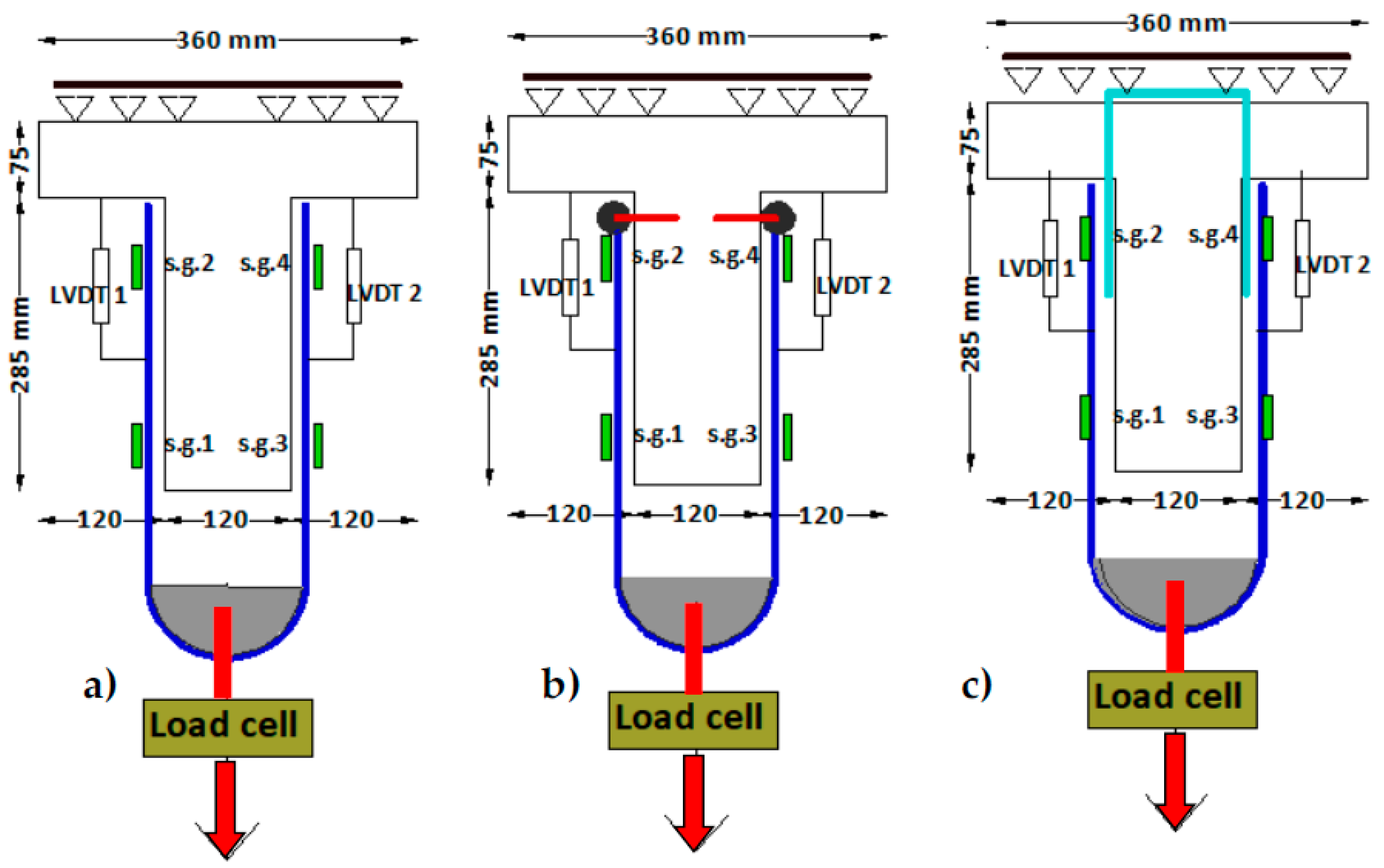
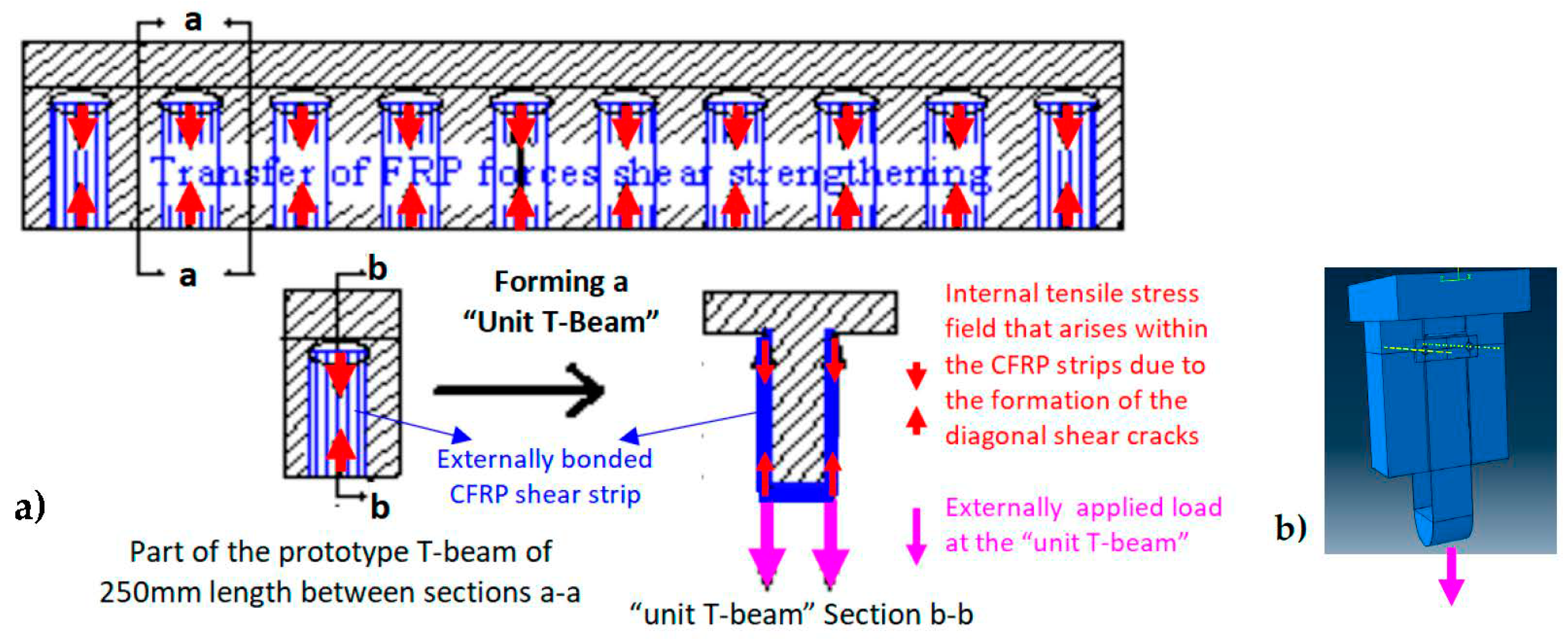
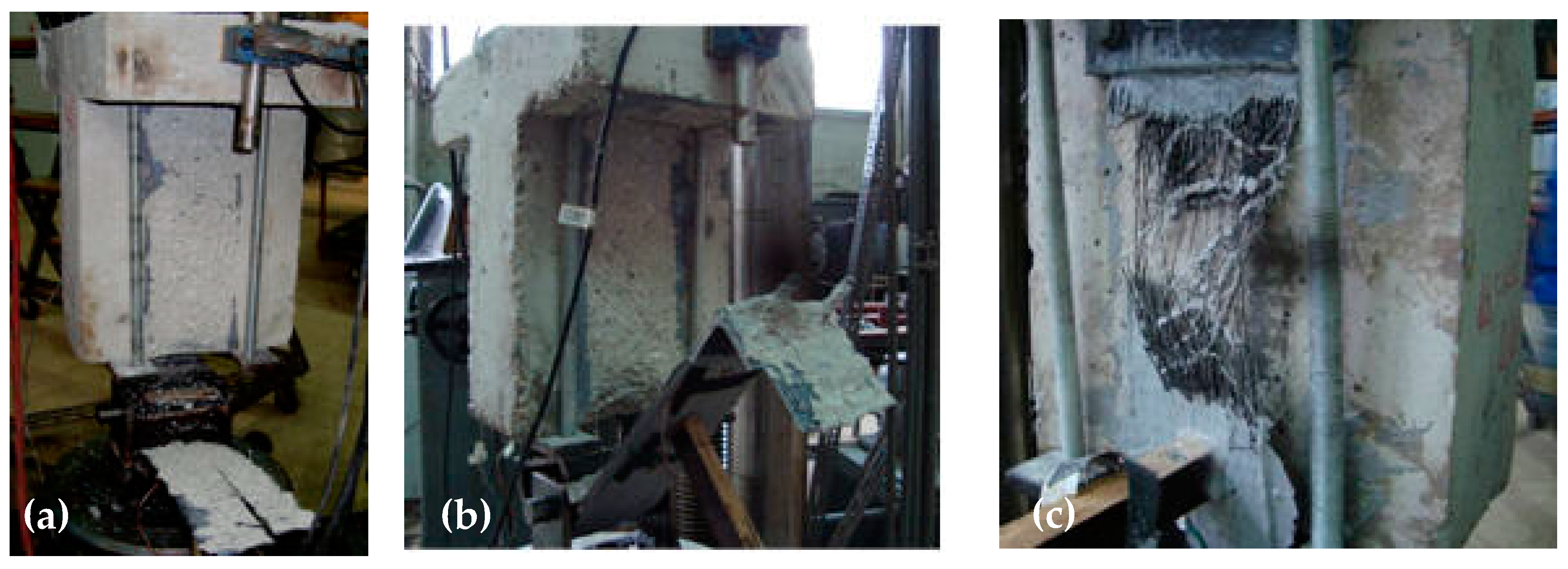
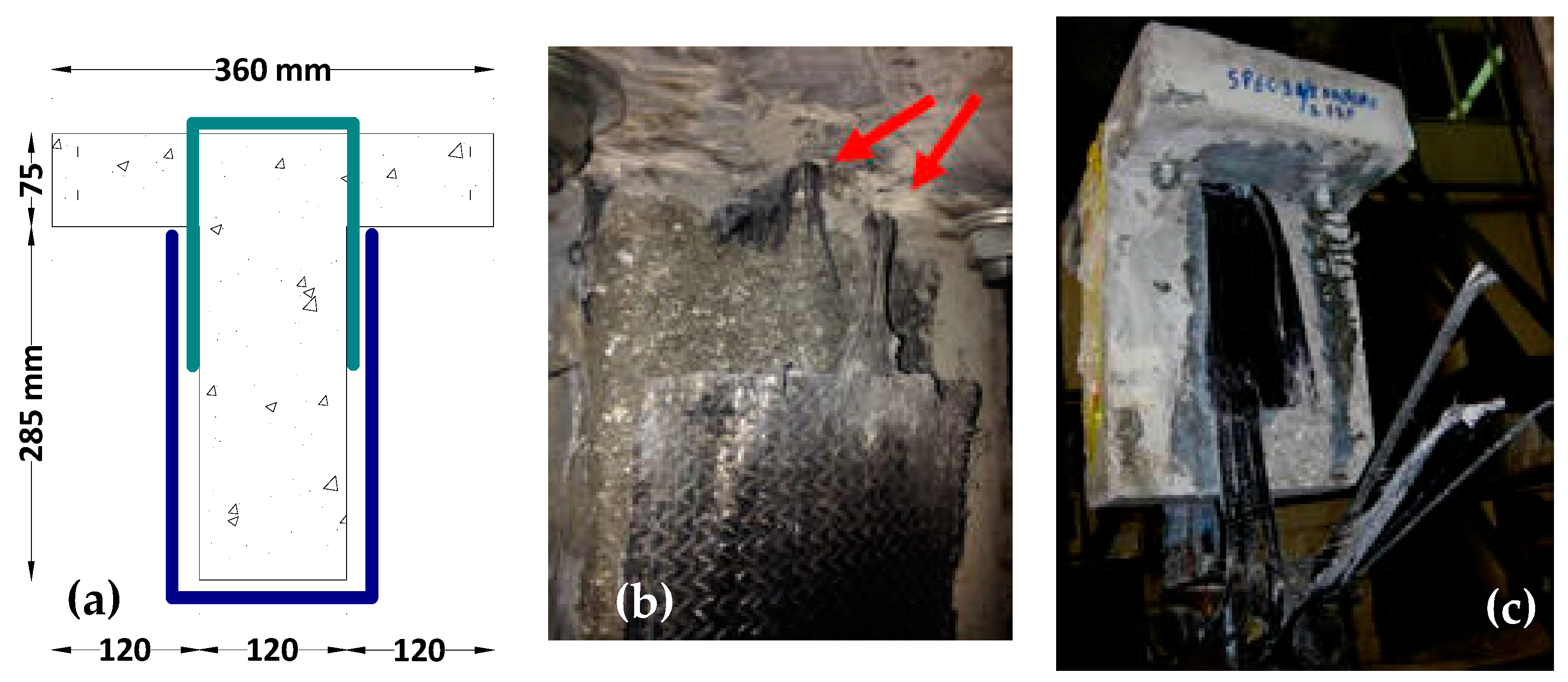
2.1. A Novel Laboratory Set-Up to Test the Force Transfer Mechanism for Open Hoop CFRP Strips with or without Specific Mechanical Anchoring Devices

Before testing the simple-supported prototype RC T-beam depicted in Figure 5a–c without or with CFRP external transverse shear reinforcement, a simple experimental procedure was conceived in order to study the force transfer mechanisms that develop in this external CFRP strip transverse shear reinforcement and the concrete volume. For this purpose, T-beam specimens were constructed of relatively small length having the same cross-section as the prototype T-beam of full length (Figure 5b). The length of these specimens, denoted as “unit T-beams”, was equal to 250 mm, which was sufficient to provide the necessary bond surface to house a CFRP external transverse shear reinforcing strip having a width of approximately 100 mm, as shown in Figure 7a,b (see also Figure 10a–c).
Figure 8a–d depicts the corresponding cross-sections of such “unit T-beam” specimens hosting a typical CFRP shear strip (100 mm wide) bonded to such a “unit T-beam” specimen with resin provided by the manufacturers, following the typical for the CFRP construction technique. A simple experimental loading procedure is used, aiming to quantify the axial tensile capacity of FRP shear strips without or with an anchoring device, which is its main forcing transfer mechanism, as indicated in Figure 9a–c, and the interaction with the concrete volume. As can be seen in Figure 8a–d, these specimens have the same cross-section as the prototype full-length RC T-beam (Figure 5a–c). However, as explained before, the length of these specimens, named “unit T-beams”, is equal to 250 mm which is a portion of the full-length prototype RC T-beam, as indicated in Figure 5a–c, Figure 7a,b, and Figure 10a–c, which is sufficient to host the width of one CFRP shear strip. In order to study the force transfer behavior of the CFRP stirrups, each “unit T-beam” is subjected to a tensile stress field by applying an external vertical load, as shown in Figure 7b and Figure 9a–c with an arrow. In this way, the force transfer mechanism under investigation was replicated, as will be explained in detail in what will follow. The experimental set-up for testing these “unit T-beam” specimens is shown in Figure 9a–c. Each of these specimens, after the CFRP strip was set approximately seven days after being bonded at both sides of the “unit T-beam” in all cases, were loaded axially as indicated in these figures. In this way, each side of the tested CFRP strip is subjected to tension with an axial tensile force resultant assumed to be ½ of the externally applied load that needs to be transferred in a way similar to the force transfer mechanism shown in Figure 7a,b. As described before, the same force transfer mechanism develops in the corresponding full-length prototype RC T-beam (Figure 5a–c and Figure 7a) in order to resist the shear, after the development of the diagonal shear cracks. The CFRP strips are bonded in both cases, with or without the presence of an anchoring device. Instrumentation was provided to monitor the variation of the externally applied tensile axial load, as well as the relative slip displacement of the top end of the attached CFRP strip and the concrete surface of the web. Four strain gauges (s.g.1 to s.g.4, shown in Figure 9a–c) were bonded in place, two at each side of the CFRP strip. These strain gauges were placed at the vertical axis of symmetry of each CFRP strip/specimen at two heights along the bonded surface as shown in Figure 9a–c. The applied axial loading in this way reproduced the state of stress that develops after the formation of diagonal shear cracks at open hoop FRP strips in prototype T-beams (Figure 7a).
The following limit states were expected to occur during the “unit T-beam” loading. (a) Debonding of the CFRP strip of the concrete bond surface; (b) tensile rupture of the CFRP strip; (c) failure of the anchoring device. In all these “unit T-beams” shear strengthening schemes, shown in Figure 8a–d and Figure 9a–c, open hoop CFRP strips were employed in an effort to avoid breaking the RC slab of the “unit T-beam”, apart from drilling relatively small diameter holes. This technique is designed to be applied in the same way to the full-length prototype RC T-beams, providing in this way a construction retrofitting technique that has a significant practical advantage. In the first scheme, the open hoop CFRP strip was simply attached at the sides (webs) and bottom of the “unit T-beam”, as shown in Figure 8b and Figure 9a, leaving the R/C slab undisturbed (Lu et al., 2005 [35], Wu et al., 2010 [36], Manos et al., 2013 [37]). Alternatively, in the second scheme, the open hoop CFRP strip was again attached at the sides of the “unit T-beam” employing this time side mechanical anchors devised by the authors [48], as shown in Figure 8c and Figure 9b. Finally, in the last shear retrofitting scheme (Figure 8d), before attaching the open hoop CFRP strip at the sides and bottom of the R/C T-beam, as was carried out before, a CFRP anchor rope, which was specially provided by the FRP industrial suppliers [52], was inserted from the top of the slab through 16 mm diameter holes that were drilled for this purpose, as shown in Figure 8d and Figure 9c. After this, CFRP anchor rope is placed in position through these holes and its fibers are spread out at the sides of the “unit T-beam” in such a way that this rope becomes flat and obtains a considerable width in order to be attached to the open hoop CFRP strip placed from the bottom of the T-beam. Epoxy resin is used to both fill the fibers of this CFRP anchor rope as well as to attach these spread rope fibers to the fibers of the open hoop CFRP strip. The same retrofitting process was also applied when upgrading in shear the prototype RC T-beam, as described in Section 2.2.

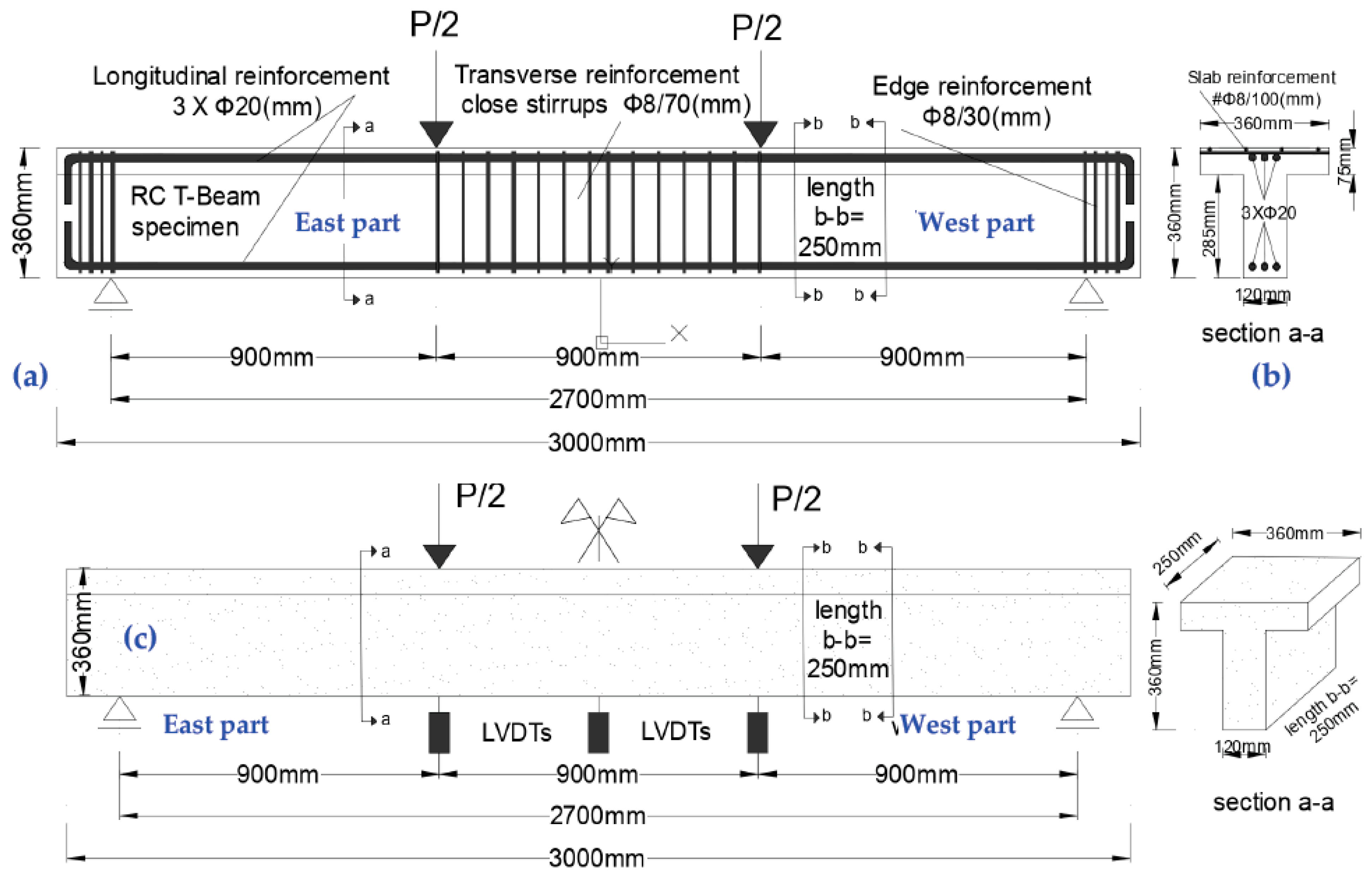
2.2. Four-Point Bending of a Prototype RC T-Beam with Various Shear Retrofirring Schemes

The full-length prototype RC T-beam described earlier (Figure 5a–c) was tested under four-point bending loading in order to quantify its shear capacity under the following four distinct stages. This prototype RC T-beam had, when tested during all four stages described in detail from (a) to (d) in what follows (Figure 5 and Figure 10a–d), a clear span equal to 2700 mm. The central vertical load was monotonic and was applied through a stiff steel girder supported at the upper side of the T-beam at two points located 900 mm from the two end vertical supports. This vertical load was measured by a load cell located at mid-span, whereas the vertical deflections were recorded by displacement transducers at mid-span as well as at the two locations coinciding with the two points of applied load as indicated in Figure 5c.
(a)
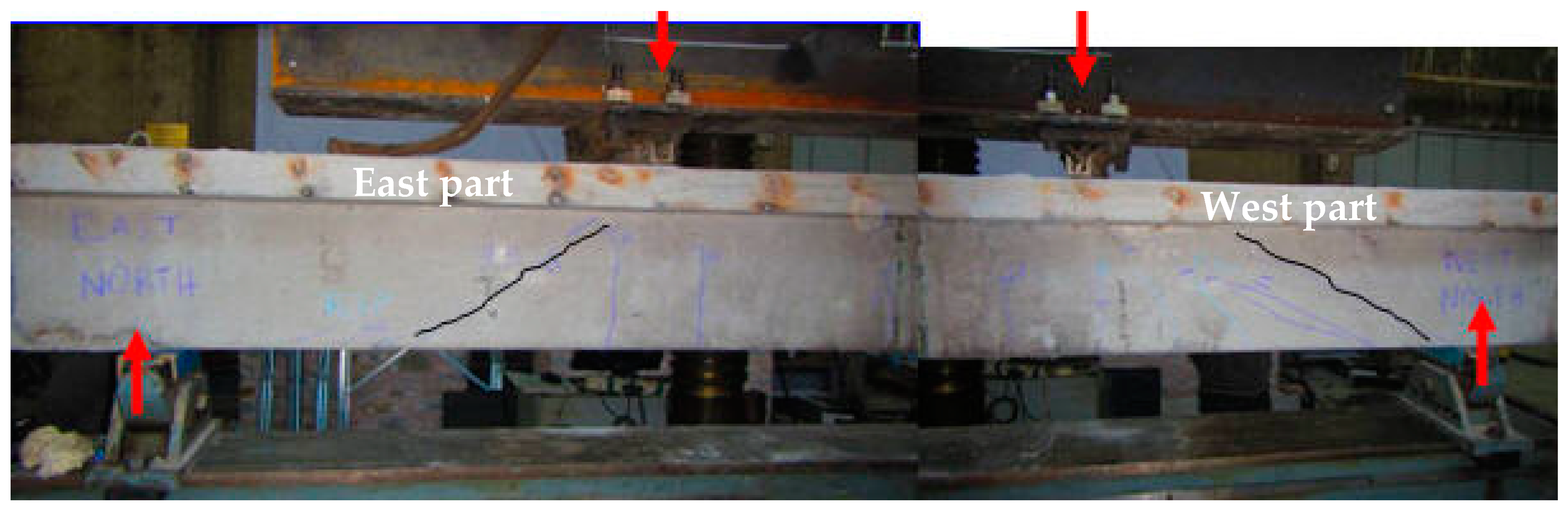
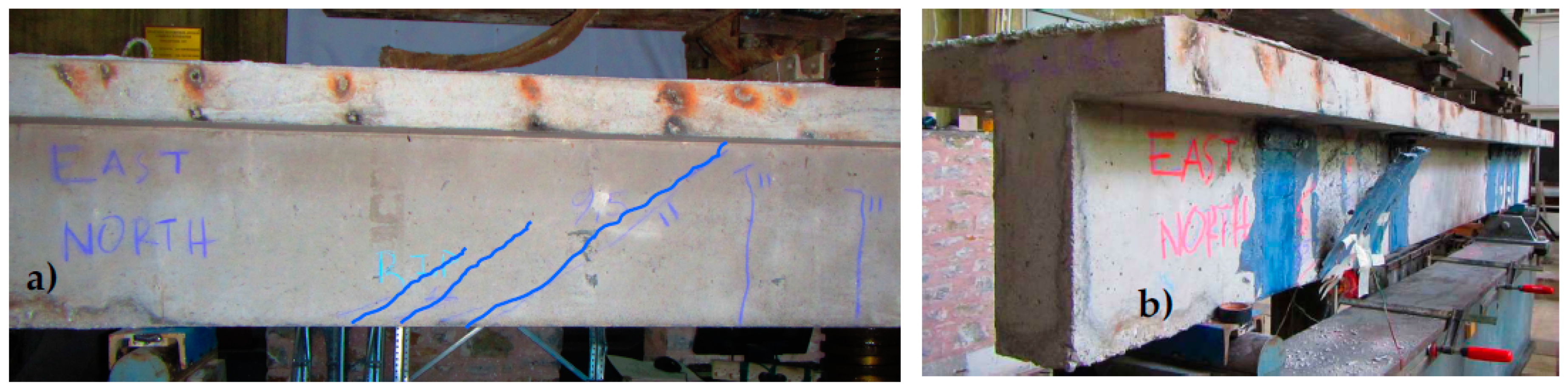
At this virgin stage, the prototype RC T-beam, having its east and west parts intentionally deficient in shear, was loaded prior to any shear retrofitting (Figure 5c) until the appearance of diagonal cracks, indicating that the shear capacity limit state was reached.
(b)
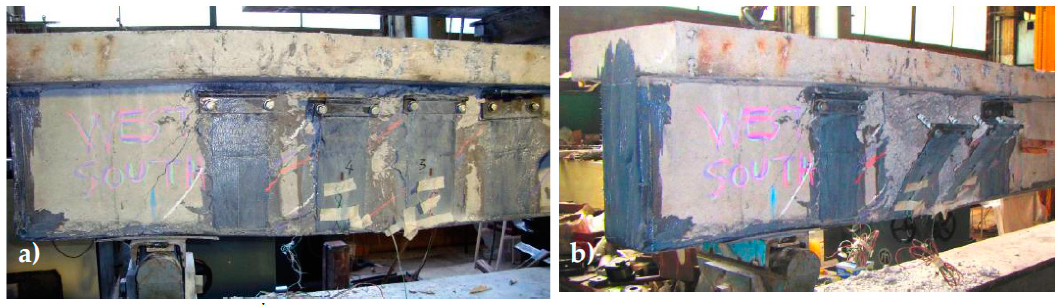
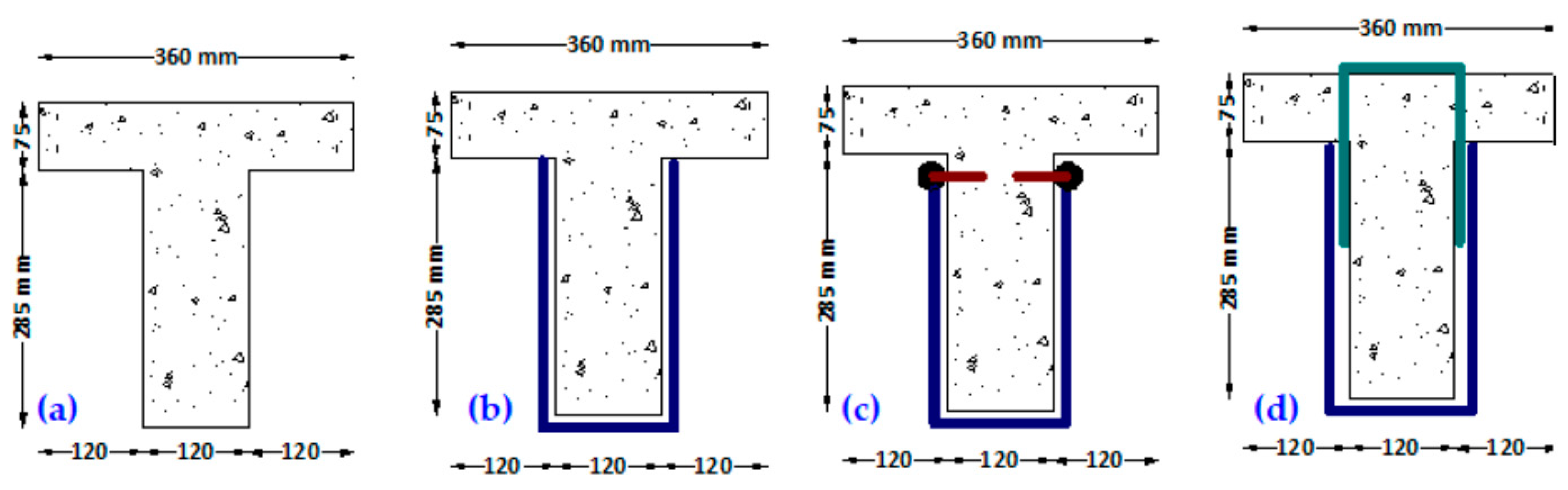
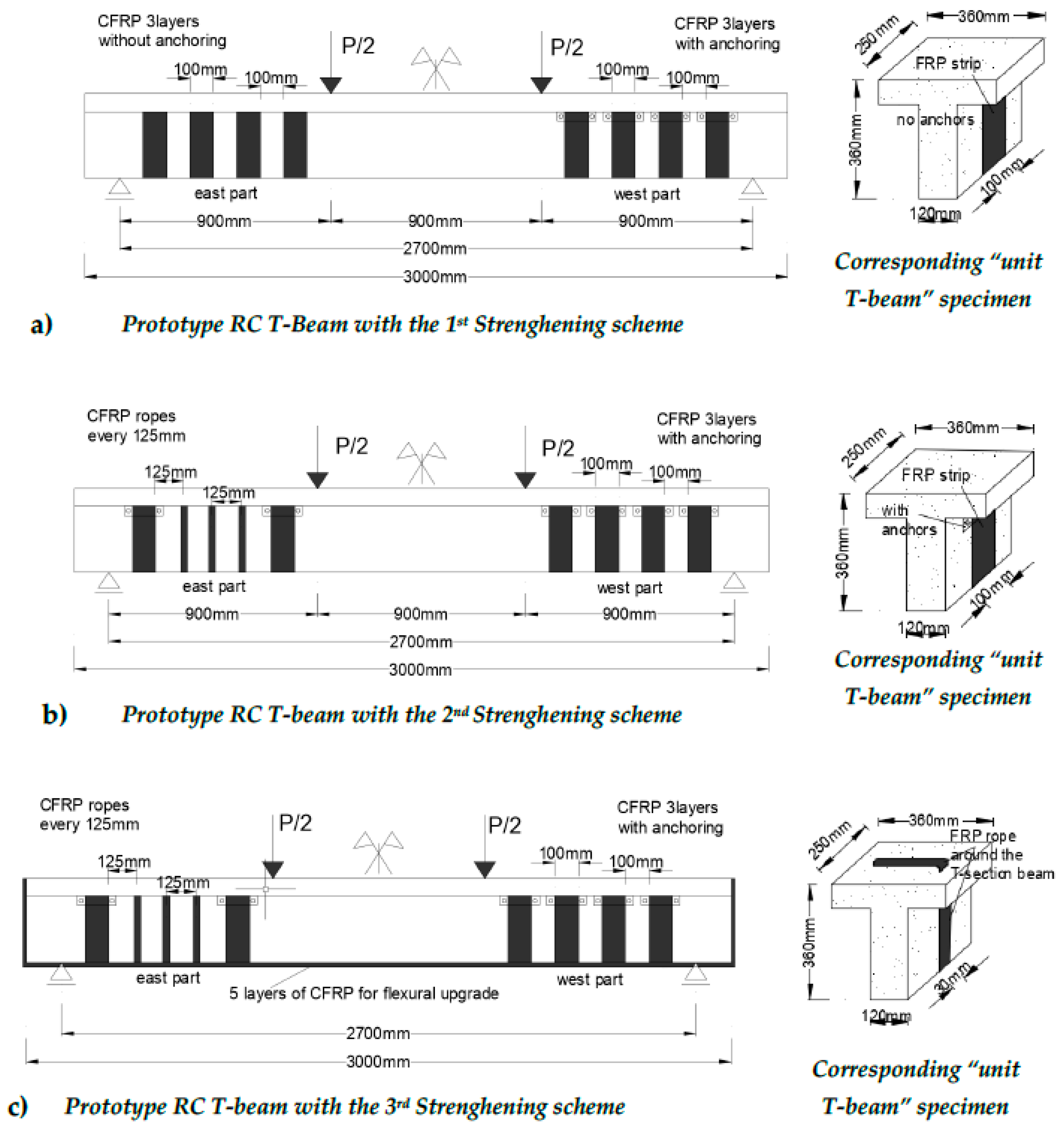
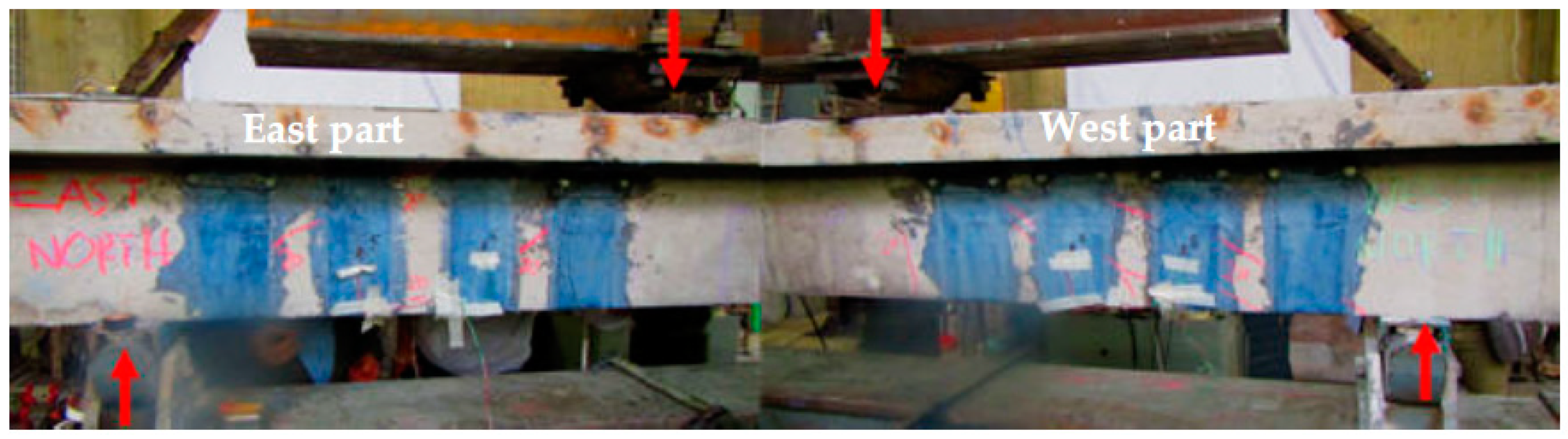
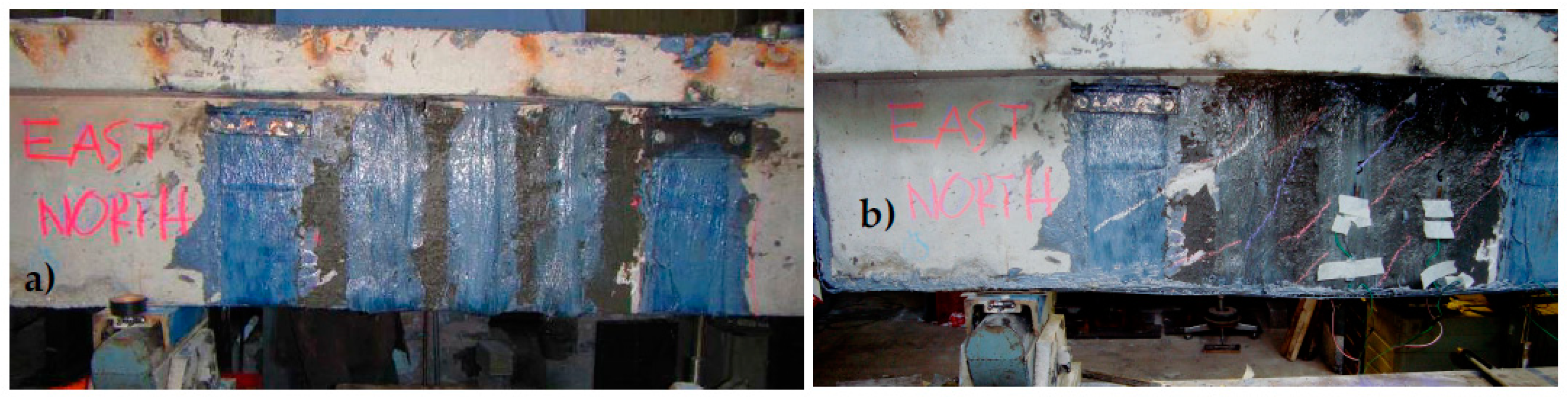
At this 2nd stage, the 1st shear strengthening scheme was applied by employing the external application of open hoop CFRP strips. At the West part, four (4) 3-layer open hoop CFRP strips were employed (Figure 10a) having 0.131 mm thickness, 100 mm width, and spaced at 200 mm intervals measured from their centerline. These West part CFRP strips employed the anchor scheme of Figure 8c and Figure 9b. At the East part, four (4) 3-layer open hoop CFRP strips were employed again, the same as at the west part of the T-beam, however, without any anchors (Figure 8b and Figure 9a). Each CFRP strip layer was 0.131 mm thick and 100 mm wide and were spaced at 200 mm intervals measured from their centerline, as were the CFRP strips at the East part. This was carried out in order to study the debonding mode of failure for the CFRP strips attached to this part. As will be discussed in Section 4, the limit state, in this case, was the debonding of the unanchored CFRP strips of the East part.
(c)
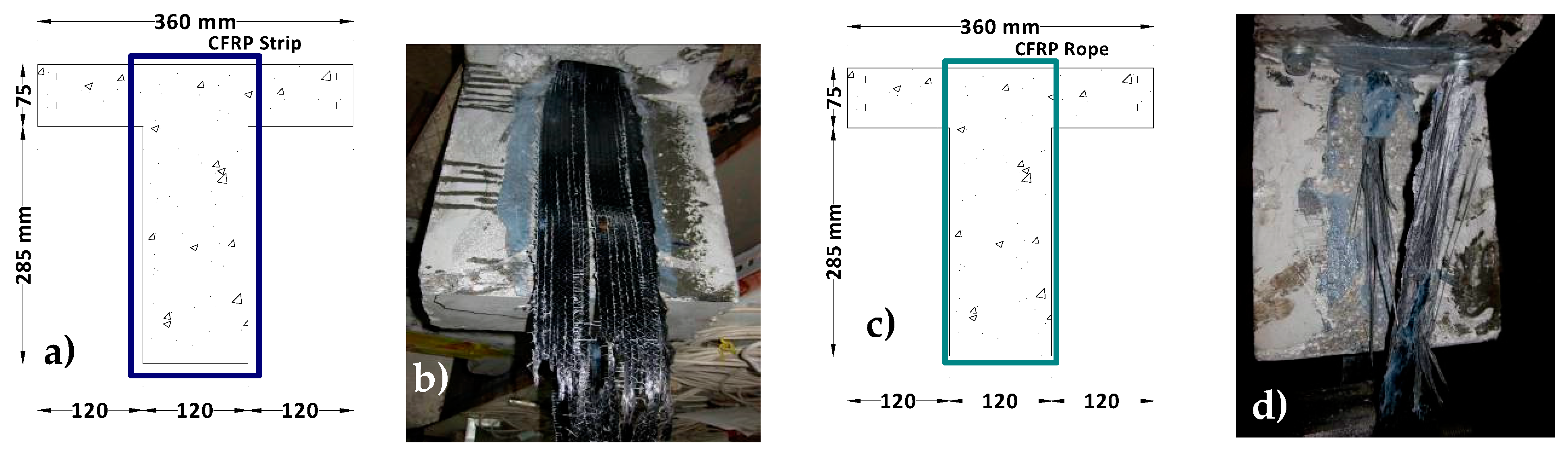
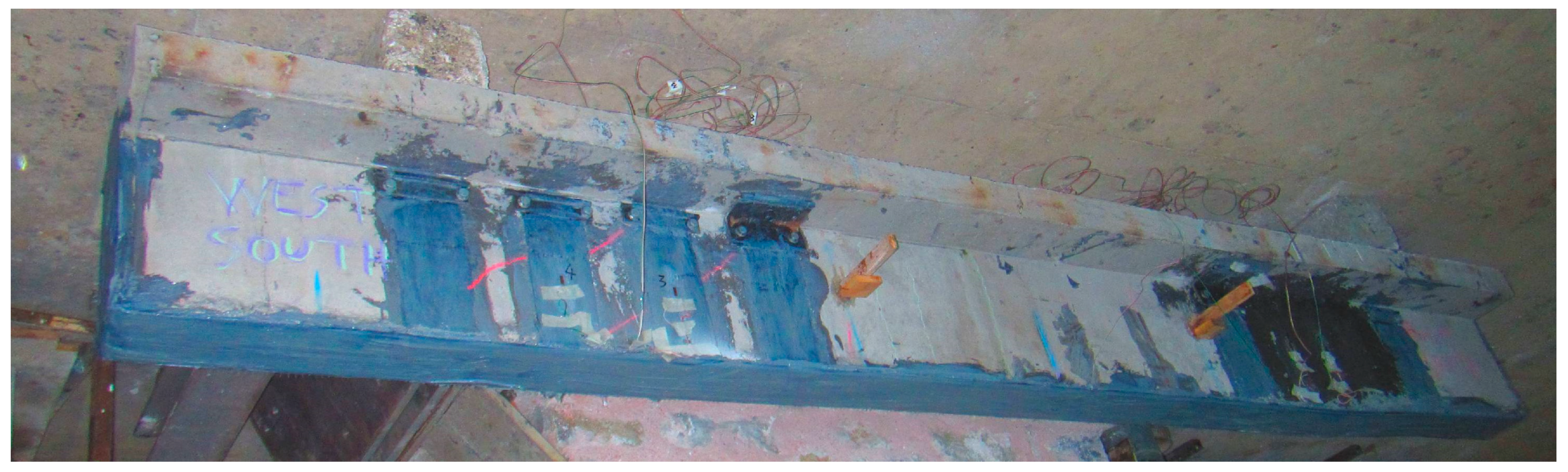
At this 3rd stage, the 2nd shear strengthening scheme was applied. The two debonded at the previous stage unanchored CFRP strips, located at the East part, were replaced by three closed hoop CFRP anchor rope stirrups each with a cross-section equal to 28.0 mm2 (see Section 3.3). Holes were drilled in the slab of the specimens for these closed hoop ropes to go through, whereas these ropes took the shape of a CFRP strip along the webs and the bottom side of the specimen. The CFRP strips anchored with steel anchored devices at the West part were left without any modification because they did not exhibit signs of any distress during the previous stage (Figure 10b).
(d)
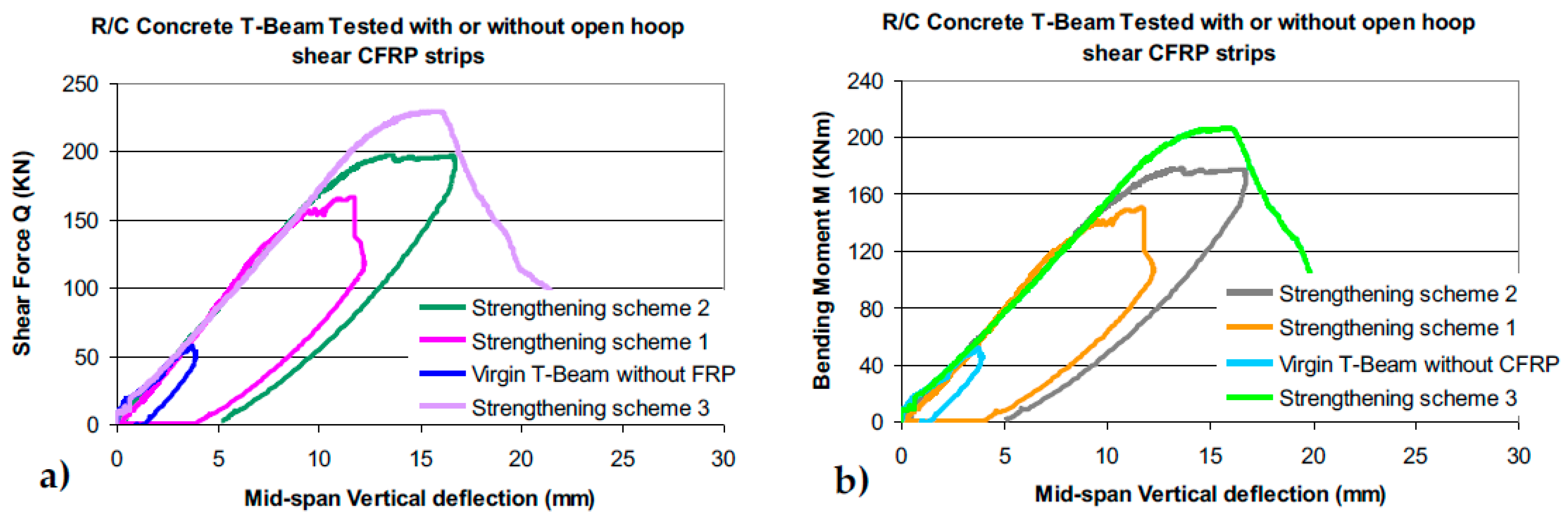
Finally, at the 4th stage, the 3rd strengthening scheme was applied. It involved flexural strengthening consisting of five (5) CFRP layers (each layer being 0.131 mm thick and 120 mm wide) attached at the bottom side of the T-beam specimen, as is depicted in Figure 10c.
The obtained response during all these four distinct stages for the examined prototype RC T-beam during the above four distinct stages are presented and discussed in Section 4.

3. Measured Response from Testing the Capacity and Force Transfer Mechanism of External CFRP Shear Stirrups without or with an Anchoring Device Utilizing “Unit T-Beam” Specimens

In what follows, the measured response obtained from two distinct sequences of tests employing “unit T-beam” specimens with various types of CFRP stirrups, with or without anchoring, is presented and discussed. Figure 11a,b depict the measured response in terms of applied total tensile load versus the strain readings that developed at the locations of the four strain gauges shown in Figure 9a–c. Figure 11a depicts a typical plot of the measured response for the CFRP strips without any anchoring (Figure 8b and Figure 9a), whereas, Figure 11b is the corresponding typical response for the CFRP strips that are provided with steel anchors in addition to bonding at the sides of the “unit T-beam” specimens (Figure 8c and Figure 9b).
It can be seen in Figure 11a, although the strain readings exhibit quite a different variation versus the applied load at the initial stages of the loading sequence, the strain value recorded by all four strain gauges becomes almost identical when the load reaches its maximum value prior to the debonding failure. The strain readings at locations s.g.1 and s.g.3 increase in a more gradual trend with the load increase. This should be attributed to the CFRP—concrete volume interaction at the bonding surface, which is not uniform from the beginning of the loading sequence. From the strain recordings, it can be seen that the CFRP strips are more stressed at the lower side (near the location where the load is applied) rather than the upper side. This process depends on the amplitude of the load and how the bond surface interacts with the CFRP strip and the host concrete surface. During a previous investigation performed by the authors, it was shown that the proper treatment of this host concrete surface prior to bonding of the CFRP strips could result in a substantial increase in the corresponding force transfer capacity [37]. As expected, the presence of the anchoring devices diminishes the importance of this bonding mechanism because the force transfer mechanism and the corresponding capacity depend primarily on the effective performance of the anchoring device. The steel anchoring device employed here has been developed and patented by the authors [48] to be effective after being through numerous laboratory tests.
As can be seen in Figure 11b, the variation of the strain readings against the load at the four strain gauge locations, when the anchor devices are present, are not very different. At the maximum load for this case, the readings at locations s.g.1 and s.g.3 are almost the same and larger than the corresponding readings at locations s.g.2 and s.g.4. This must be attributed to the fact that the presence of the anchoring device disturbs the uniformity of the axial stress field at close proximity to these anchoring devices, whereas this axial stress field is certainly less disturbed at the level of s.g.1 and s.g.3. Following this rationale, the maximum average axial strain value measured at locations s.g.1 and s.g.3 is utilized in Table 2, which includes a summary of the obtained results

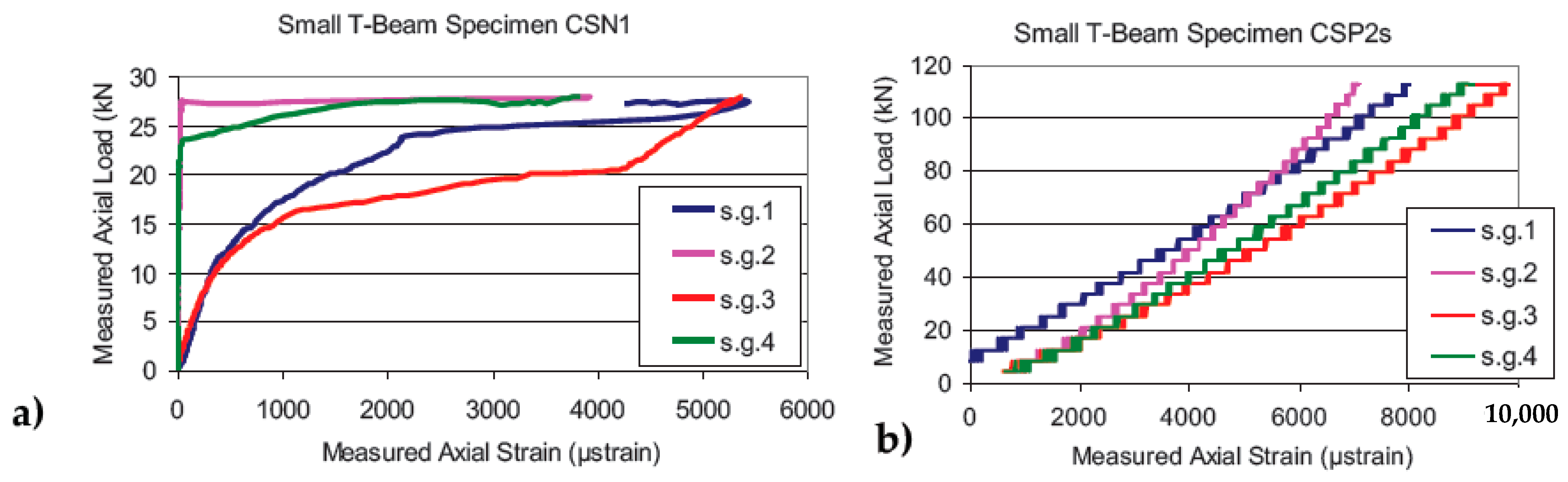
3.1. “Unit T-Beams” with Open Hoop CFRP Strips Employing Specific Mechanical Anchoring Devices

The tested “unit T-beam” specimens in this sequence are listed in column (1) of Table 2 with their code name stating the presence (or not) of an anchoring device for the CFRP strips. Moreover, the preparation of the concrete surface where the CFRP is attached is also indicated. Column 2 of Table 2 lists the average maximum value of the axial strain that was measured at locations s.g.1 and s.g.3 [53]. Column (3) of Table 2 lists the maximum total applied load value during each test. Column (4) lists the value of the total axial load based on the measured average maximum axial strain value (column 2) and the measured Young’s modulus value of the used CFRP strips equal to 234 GPa. It is assumed that the CFRP strips of the tested specimen develop this maximum strain value for the whole width of its cross-section at both sides of the “unit T-beam”. Each CFRP layer had a thickness of 0.131 mm and a width of 100mm. A reasonably good agreement can be seen by comparing the measured total maximum load values (Table 2 column 3) with the corresponding values calculated in the way described earlier (Table 2 column 4). It can be concluded that, for design purposes, it is very important to be able to ascertain with confidence the axial strain level that can be assumed to arise in these FRP strips. Towards this objective, it is important to approximate the effectiveness of the bonding surface or of a specific anchoring device and on this basis to adopt the appropriate axial strain value for the FRP strips. The following summarizes the most important observations of the behavior exhibited by either the used CFRP strips or the specific mechanical anchoring devices used in these tests.
(a1) The debonding of the CFRP strip from the concrete surface was observed for strain/stress levels well below the strain limits given by the manufacturers of the FRP materials. The strain/stress levels accompanying this debonding mode of failure continually decrease when one increases the layers of the FRP strip, and consequently its thickness and cross-sectional area, rendering such layer increase totally ineffective unless it is combined with some type of anchoring. This type of failure, which is expected to occur in similar practical applications, is depicted in Figure 12a as observed during the current investigation.
(a2) From the preceding discussion, it becomes obvious that the debonding mode of failure prevails in almost all cases where an open hoop FRP strip is simply attached without any anchoring. However, the effective anchoring of such an open hoop FRP strip is not easy. Thus, the second category of modes of failure includes limit states in which the final debonding and failure of the FRP strip is a result of the interaction between the FRP strip and the used anchoring scheme. In many cases, the employed anchoring scheme is insufficient to withstand the level of axial force that the FRP strip can withstand by itself in ideal axial tension conditions leading to either local failure of parts of the anchoring scheme or local failure of the FRP strip in areas neighboring the anchor or both. Again, the increase of the layers of the FRP strip, and consequently of its thickness and cross-sectional area, results in a corresponding increase in the demands on the various parts of the anchoring scheme to withstand this increased CFRP strip capacity leading to partial successive failure of the anchoring device. This type of failure is depicted in Figure 12b as was observed during the current investigation for an anchoring scheme that proved ineffective and is not reported further in this paper.
(a3) The final mode of failure is in a form of tensile failure of the FRP strip. The closer this tensile failure resembles an ideal symmetric axial tensile failure of the FRP strip the higher the axial strain/stress levels that would develop, thus, resulting in higher exploitation of the capabilities of the FRP material. This desirable FRP strip performance is observed when the used anchoring scheme is effective in inhibiting any asymmetric local deformation patterns for the axial tensile force levels that correspond to such relatively high strain/stress levels of the FRP strip. The final limit state condition is that of the fracture of the FRP strip that is obviously preceded by its debonding. This type of failure is depicted in Figure 12c, as observed during the current investigation. For a given effective anchoring scheme linked with an FRP strip having a given number of layers, a successive increase in the number of layers will eventually lead to the failure of the anchoring scheme, unless it is properly redesigned.

3.2. “Unit T-Beams” with Open Hoop CFRP Strips Employing CFRP Anchor Ropes

This section presents the measured response obtained from an additional loading sequence investigating a different type of anchoring scheme (Figure 13a) utilizing again the “unit T-beam” loading process. This time, before attaching the open hoop CFRP strip at the sides and bottom of the R/C beam, a CFRP anchor rope is inserted from the top through 16mm diameter holes that are drilled in the R/C slab of the T-beam for this purpose. The effective cross-sectional area of this CFRP rope is equal to 33.1 mm2 and Young’s modulus is equal to 240 GPa. After this CFRP anchor rope has been placed in position through these holes, its fibers are spread at the sides of the beam in a way that this rope becomes flat and obtains a considerable width in order to be attached to the single-layer open hoop CFRP strip, which is put in place from the bottom of the T-beam. This anchoring scheme was studied in two different ways. First, one anchor rope was used with its axis located at the mid-axis of the width of the open hoop CFRP strip.
First, there are the three specimens, using a single anchor rope, with the code name SW600C/1 No1, No2, and No3 (column1, Table 3). In addition, a double anchor rope was placed side-by-side along the width of the open hoop CFRP strip. There are four specimens utilizing this double anchor rope with the code name SW600C/2 No1, No2, No3, and No4 (coulmn1, Table 3). In column 2 of Table 3, the total maximum measured load for each specimen is listed, whereas, column 3 lists the average values of the axial strains measured at both sides of the CFRP strip at the time instant that the specimen was subjected to the maximum load value of column 2. Column 4 of Table 3 lists the axial load valued obtained on the basis of the strain values of column 3 (with the value of Young’s Modulus equal to 234 GPa) and the cross-sectional area of the CFRP strip. Because this anchoring scheme used in all these cases is not expected to disturb the distribution of the axial stress field at the location of the four strain gauges, the average value of all four strain gauges during the occurrence of the maximum load is utilized in Table 3. The following are the main observations.
(a2) When a single CFRP rope was used in the anchoring scheme of the 1-layer open hoop CFRP strip, the observed failure was mainly at this anchor rope (see Figure 13b). On the contrary, when double CFRP anchor ropes were used to anchor the open hoop CFRP strips the obtained tensile capacity resulted in an effective anchoring scheme leading to the tensile fracture of the single-layer CFRP strip (Figure 13c).
(b2) As can be seen from the obtained maximum axial load values listed in Table 3 (column 2), when a single CFRP anchor rope is used the average maximum axial load value is equal to 66.12 kN (SDEV = 4.54 kN, 6.9% of the average maximum value). In comparison, when double CFRP anchor ropes are used then the average maximum axial load value is equal to 86.12 kN (SDEV = 19.58 kN, 22.7% of the average maximum value), representing a substantial increase. The use of double anchor ropes also succeeded in changing the mode of failure from the anchor rope to the CFRP strip in all cases, which should be considered as a preferable performance.
(c2) A relatively large SDEV value in the axial tensile load capacity results can be seen when double anchor ropes are used. This indicates a degree of uncertainty in achieving desired high values of tensile bearing capacity when applying a relatively large number of anchor ropes. The largest measured tensile capacity when using double anchor ropes is equal to 105.98 kN, which represents a 60% increase from the measured average capacity when using a single anchor rope. At the same time, the smallest bearing capacity when using double anchor ropes is equal to 61.86 kN, which represents a 7% decrease from the measured average capacity when using a single anchor rope. This should be attributed to the interaction between the anchor ropes and the CFRP strip at the common bond surface and should be investigated further.
(d2) Reasonably good agreement can be seen by comparing the measured total maximum load values (column 2 of Table 3) with the corresponding values calculated in the way described earlier (column 4 of Table 3), with the exception of the specimen listed in the last row of Table 3. It can be again concluded that for design purposes it is very important to be able to ascertain with confidence the axial strain level that can be assumed to be able to be sustained in these CFRP strips. Towards this objective, it is important to approximate the effectiveness of the bonding surface or of a specific anchoring device and on this basis to adopt the appropriate axial strain value for the CFRP strips.

3.3. “Unit T-Beams” with Either Closed Hoop CFRP Strips or Closed Hoop Single CFRP Anchor Rope

In order to have a direct measurement of the tensile capacity of either the CFRP strips themselves or the CFRP anchor ropes when in position, extra “unit T-beam” specimens were constructed whereby the CFRP strip (specimens ref-1 and ref-2, Figure 14a,b) and the CFRP rope (specimens SWFX No1, No2 and No3, Figure 14c,d) were accommodated in a closed hoop formation and were subjected to the same loading arrangement depicted in Figure 9c. The obtained results are listed in Table 4.
As can be seen from the obtained maximum axial load values listed in Table 4, when a closed hoop single CFRP anchor rope is used the average maximum axial load value is equal to 70.79 kN (SDEV = 4.21 kN, 5.9% of the average maximum value). When a closed hoop single CFRP strip is used, the average maximum axial load value is equal to 85.63 kN (SDEV = 18.43 kN, 21.52% of the average maximum value). From these maximum load values, it can be concluded that when the used single layer CFRP strip is anchored with a single CFRP anchor rope the tensile failure is expected to occur at the rope (70.79 kN < 85.63 kN). On the contrary, when the used single layer CFRP strip is anchored with a double CFRP anchor rope the tensile mode of failure is expected to occur on the CFRP strip (85.63 kN < δ * 70.79 kΝ, with the value of δ being larger than 1.25 signifying the degree of effectiveness of the double anchor rope when compared to that of a single anchor rope, given the uncertainty of the performance of multi-anchor ropes described in Section 3.2 and Table 3.

4. Results of the Measured Behaviour of a Prototype R/C T-Beam in Its Virgin Condition as Well as Being Upgraded in Shear with Various External CFRP Strips

In what follows, the measured response of the tested prototype RC T-beam during the four distinct stages of sequentially applying is described in Section 2.2. CFRP strip shear retrofitting schemes are presented and discussed.

4.1. Virgin Prototype RC T-Beam without Any External CFRP Strip Shear Reiforcement

Initially, this prototype RC T-beam was loaded at its virgin stage until the shear limit-state was reached with the appearance of diagonal shear cracking patterns at the East and West parts for a maximum shear force value equal to 57.39 kN. This is depicted in Figure 15.

4.2. Prototype RC T-Beam witht External CFRP Strip Shear Reiforcement Which Includes at the East Part Unancored CFRP Strips (1st Shear Strengthening Scheme)

The limit state this time (1st shear strengthening scheme, Figure 16) resulted, as expected, in the debonding mode of failure of the East side unanchored CFRP strips as shown in Figure 17b for a shear force equal to 166.77 kN. The corresponding maximum bending moment value is equal to 150.09 kNm. This shear force value is more than three times larger than the shear capacity measured for the un-strengthened virgin T-beam. The variation of the applied shear force versus the vertical deflection of the virgin and the strengthening with this 1st shear strengthening scheme T-beam is depicted in Figure 18a, whereas, Figure 18b depicts the comparison of the measured bending moment response between the Virgin T-beam and the T-beam having been retrofitted with the 1st strengthening scheme (a-Shear force versus the deflection at mid-span, b-Bending moment versus the deflection at mid-span). A comparison of the modes of failure after the maximum load was reached is depicted in Figure 17a for the virgin T-beam without any external shear CFRP strips (development of diagonal shear cracks), and in Figure 17b for the T-beam retrofitted according to the 1st shear strengthening scheme. As can be seen in Figure 17b, the limit state, in this case, was the debonding of the open hoop CFRP strips without anchoring. It is important to underline that the West part of this T-beam, although subjected to the same shear force level as the East part, did not show signs of any distress. This is due to the presence of the effective anchors that accompanied the open hoop CFRP strips at this location. The design of this CFRP anchoring scheme was facilitated by specially designed software [47] as well as valid numerical simulations [51].

4.3. Prototype RC T-Beam witht External CFRP Shear Reiforcement Having all the CFRP Stirups Either Anchored at the West Part or Closed CFRP Rope Both at the East Part (2nd Shear Strengthening Scheme)

At this stage (2nd shear strengthening scheme), the two debonded at the previous stage unanchored CFRP strips, located at the East part, were replaced by three closed hoop CFRP anchor rope stirrups similar to the one tested in Section 3.3 (see Section 2.2 and Figure 10b). These closed hoop CFRP ropes can be seen in Figure 19a, whereas, Figure 19b depicts the traces of the diagonal cracks. Further development of these diagonal cracks was successfully prohibited by these closed hoop anchor ropes.
Figure 20a,b depicts the comparison of the measured response between the Virgin T-beam and the T-beam having been retrofitted with either the 1st or 2nd strengthening scheme (a-Shear-force versus the deflection at mid-span, b-Bending-moment versus the deflection at mid-span). This 2nd strengthening scheme was capable of upgrading the shear resistance of the specimen in such a way that the flexural mode of failure developed this time. This is evident from the ductile nature of the variation of either the shear force (Q, Figure 20a) or the bending moment (M, Figure 20b) response versus the deflection at mid-span. The maximum shear force recorded for the 2nd shear strengthening scheme was equal to 197.43 kN and the corresponding maximum bending moment value was equal to 177.68 k Nm.

4.4. Prototype RC T-Beam witht External CFRP Shear Reiforcement Having All the CFRP Stirups Either Anchored at the West Part or Closed CFRP Rope Both at the East Part Together with a Flexural Upgrade (3rd Strengthening Scheme)

Finally, for the 3rd strengthening scheme 3, whereas all types of external shear CFRP stirrups were left unchanged from the previous stage, a flexural strengthening was added consisting of five (5) CFRP layers (see Section 2.2). This is also depicted in Figure 21 (see also Figure 10c). This is evident from the measured shear force (Q) or bending moment (M) response versus the deflection at mid-span depicted in Figure 22a,b, respectively. The maximum shear force recorded for the 3rd shear strengthening scheme was equal to 229.55 kN and the corresponding maximum bending moment value was equal to 206.60 kNm. The used flexural strengthening scheme prohibited the development of any flexural mode of failure, as was the case for the 2nd strengthening scheme, and allowed the development of the shear limit state. This was of course a research objective, whereas the design objective is the ductile flexural response to prevail. In Figure 23a the West part of this 3rd strengthening scheme of the prototype RC T-beam prior to testing is shown; the externally bonded CFRP strips anchored with mechanical anchor [48] can be seen in this figure. The same West part of this T-beam is shown in Figure 23b at the end of testing for this 3rd strengthening scheme. The amplitude of the stress levels that developed at the CFRP strips and their anchors during this loading sequence led to the partial failure of the used anchoring devices when the applied load reached its maximum value as sown in Figure 23b. The widening of the shear diagonal cracks at this West part and the consequebt partial crushing of the concrete volume in the anchoring region reduced considerably the effectiveness of this anchoring scheme and led to the observed considerable decrease in the shear capacity of the tested T-beam (Figure 22a).

5. Discussion of the Shear Performance of the Prototype R/C T-Beam without and with Shear Strengthening

This section summarizes the observed performance of the tested prototype RC T-beam when virgin and compared it with the corresponding performance of the same T-beam being retrofitted with the described in Section 4 strengthening schemes 1st, 2nd, and 3rd.
Table 5 lists the measured response in terms of the maximum measured values of shear force (Qm) and bending moment (Mm) for the virgin T-beam, and the corresponding values for the T-beam being retrofitted in three distinct stages as described in Section 2.2 and Section 4. The same table also lists predicted maximum shear force and bending moment values, as will be described in what follows. In columns (1) and (2) of this table, the description of this T-beam and the relevant retrofitting scheme is described in brief. Columns (3) and (4) of Table 5 list the measured maximum values of the shear force and the bending moment, respectively. In column (3), the measured increase in the maximum shear force (Qm) that could be resisted during the relevant test, as a result of the applied strengthening scheme, is also listed. These increased values (%) were obtained using as a basis the maximum shear force measured for the virgin T-beam. It must be underlined again here that this specimen was intentionally under-designed in shear. Because of this, the increase in shear capacity that was finally achieved reached 300%. However, in practical cases whereby the structural member will possess a certain level of initial shear capacity from the existing internal shear steel reinforcement, the shear capacity increase by such retrofitting is expected to reach a rather modest value. The following are the important points that must be considered here from the presented results.
-
The 1st Strengthening scheme has the limitation of employing unanchored CFRP strips. This limitation should be considered in design as it means that the full tensile potential of the applied CFRP strip layers is not fully exploited.
-
This limitation was dealt with by the 2nd strengthening scheme where all the parts of the external shear CFRP reinforcement were either CFRP strips provided with mechanical anchors (East) or closed hoop CFRP anchor ropes (West). This resulted in such a considerable upgrade of the resulting shear capacity that this prototype RC T-beam could not be forced enough in order to reach its shear capacity at this retrofitting stage. It instead reached its flexural limit state.
-
Because of this, the 3rd strengthening scheme was applied in order to upgrade the flexural capacity of the prototype RC T-beam at this stage in order to prohibit the flexural failure and to lead towards reaching again a shear limit state. This time, the shear limit state appeared in the form of partial failure of the employed mechanical anchoring devices, which became ineffective, as described. This fact points to the importance of designing the anchoring system to be able to sustain the full potential capacity of the CFRP strips that are supported by it. As was underlined with the first comment, the full tensile potential of the applied CFRP strip layers is not exploited either because of the premature debonding or of the failing of the employed anchoring devices.
-
All the above require a careful step-by-step design of all these partial aspects of a shear retrofitting scheme, as will be also discussed below.
In column 6 of Table 5, the predicted shear force (Vp) and bending moment (Mp) capacity values are listed based on the detailing of the original virgin T-beam together with all the additional CFRP detailing of each retrofitting scheme. Towards this objective, a software built for this purpose was utilized, that calculated both the shear and flexural capacity of such a T-beam [49] at the various stages. The calculations to obtain the flexural capacity are based on a well-established theory of the RC cross-sections assuming as limit states either the yield and fracture of the longitudinal tensile reinforcement or the limit tensile strain (0.7%) of the longitudinal CFRP strip attached at the bottom side of such a T-beam together with the compressive limit-state of the top fiber of the cross-section (0.3% limit compressive strain). All the measured geometric details of the T-beam cross-section and mechanical properties of all the used materials (see Section 2), are utilized by this software as input data. Towards obtaining the shear capacity predictions (Vp) for the tested T-beam, use is made of the contribution by the concrete part (Vc) adopting the formula proposed by Zsutty [58]. The contribution of the various schemes of CFRP external shear reinforcement (VCFRP) is added on the concrete contribution, as shown by the following Equations (1) and (2), where the cross-section of a single CFRP strip is equal to ACFRP the CFRP Young’s modulus is equal to ECFRP and εCFRP is the maximum tensile strain level assumed to develop at the CFRP strip being crossed by the diagonal shear cracks. Coefficient 2 at the front of the right part of Equation (2) accounts for the fact that the development of the diagonal shear crack is resisted by both sides of the hoop-shaped shear reinforcement surrounding the T-beam cross-section from both sides.
Vp = Vc + VCFRP
VCFRP = 2·ACFRP·ECFRP·εCFRP
The provisions of the Greek guidelines [12] for retrofitting RC structural elements with externally attached FRP strips are utilized to calculate the CFRP external shear contributions. These guidelines provide upper acceptable limits for the tensile strain (εCFRP) that such external shear reinforcement is allowed to develop. This tensile strain limit has a relatively low value for unanchored FRP strips, thus taking into account the debonding mode of failure. As indicated by Equation (1), the shear CFRP strip contribution is added to the shear contribution of the concrete resulting in the shear force predictions assuming debonding limit-state which is denoted as strip debVp in Table 5 column 6. The presence of an anchoring system or closed hoop strips leads to accepting relatively higher tensile strain values (εCFRP) than before, according to the same provisions. In this case, the presence of anchoring or the nature of closed hoops is assumed to lead to the tensile rupture of the FRP material as limit-state. Again, applying Equation (2) and assuming as limit-state the rupture of the CFRP (either strip or rope) the corresponding shear capacity predictions are obtained which are denoted as either strip rupVp or rope rupVp (Table 5 column 6). In predicting the shear force or bending moment capacities, in the way described, the safety coefficients adopted in relevant design guidelines were set to be equal to 1. This way of obtaining the shear force capacity of RC beams strengthened by external FRP shear reinforcement is in line with the rationale followed by many relevant design guidelines [12,59,60,61] with a varying degree of complexity. D’Antino and Triantafillou [62] present an extensive review of a wide range of such design guidelines utilizing an extensive database of experimental results of RC beams strengthened with externally applied shear FRP retrofitting schemes. The following summarizes the main observations from comparing these predictions with the corresponding measurements.
-
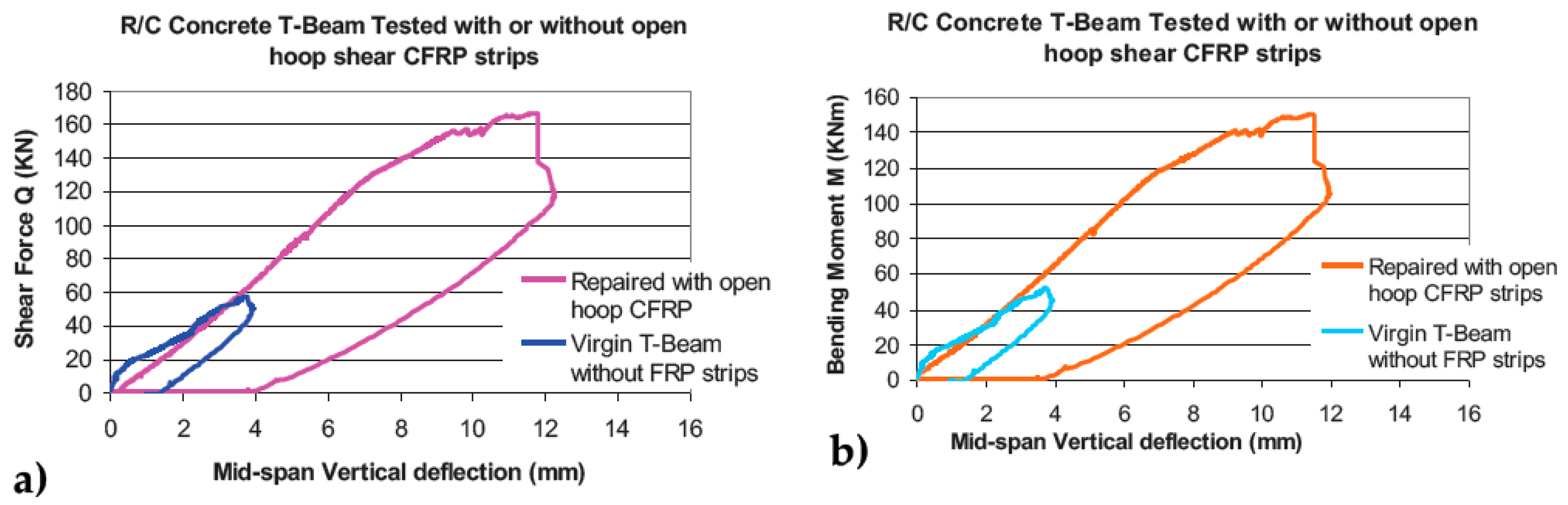
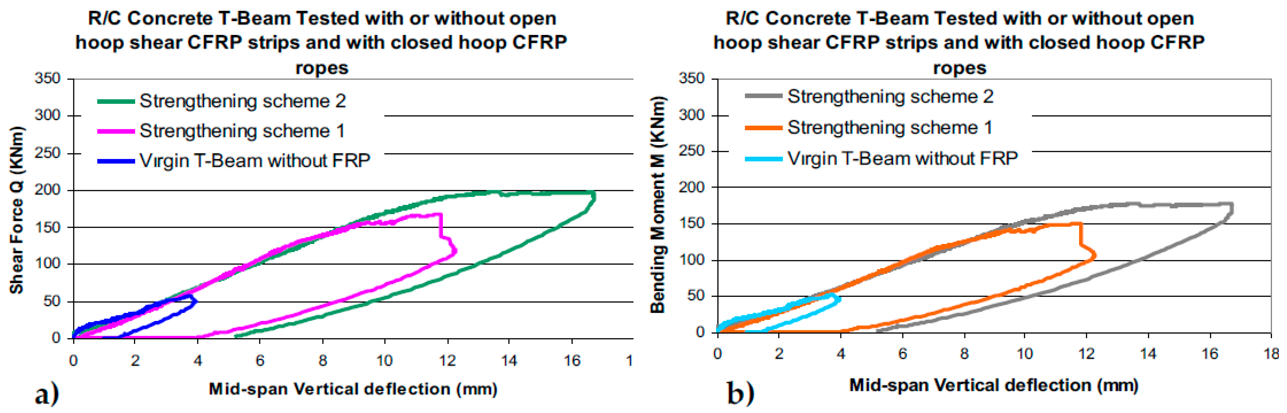
The shear force capacity of the concrete, as found by the virgin beam results, is very well predicted. The concrete shear force resistance is also kept when predicting the total shear force resistance for the 2nd, 3rd, and 4th strengthening scheme. This is due to the fact that the formation of diagonal cracking during the loading of the virgin T-beam at all subsequent stages did not reduce this shear resistance because the loading stopped before any significant widening of these diagonal cracks could take place. All the subsequent shear retrofitting schemes managed to prohibit any detrimental widening of these diagonal cracks till the last stage (last phase of loading during the 4th strengthening scheme). This can be seen in Figure 23a,b.
-
For the 2nd strengthening scheme, which exhibited flexural limit state, its measured flexural capacity of the tested RC T-beam is also very well predicted Therefore, the discrepancies between measured and predicted capacity values are limited to the CFRP shear contributions.
-
For the 1st shear strengthening scheme the predicted shear capacity value, based on the debonding limit state, is equal to 69% of the measured value.
-
The 2nd shear strengthening scheme cannot be used for this purpose because during this testing stage the shear capacity was not reached due to exceeding the flexural limit state.
-
The 3rd shear strengthening scheme can be used with certain reservations because it is based on the assumption of the rupture of either the CFRP shear strips with anchors or the CFRP closed hoop anchor ropes. However, the actual limit state, as described, was that of partial damage of the used mechanical anchors. This is a topic of a more detailed analysis beyond the current presentation. Despite this limitation, a comparison of the predicted shear capacity values (based on the assumed strip rupture limit state) with the measured value (actually resulting from the anchor damage) reveals that the predicted shear capacity value corresponds to approximately 65% of the measured value.
-
The above discrepancies would be larger if the comparison would be made excluding the concrete shear force contribution. In this case for the case of debonding limit-state, the predicted CFRP contribution is equal to 58.6% of the measured value which is almost the same as for the case of the rupture limit-state whereby the predicted CFRP contribution is equal to 58% of the measured value.
-
A possible explanation for these discrepancies is the inherent conservativism in the design guidelines reluctant to adopt either higher values of axial tensile strains for these externally applied CFRP shear reinforcement than the ones assumed or the participation of a larger number of CFRP strips than the ones assumed. This conservativism is justified, up to a point, because during practical applications in situ conditions, such as the preparation of the bond surface, the rounding of the corners, the proper attachment of the CFRP strips or ropes were found to have an important influence on the final effectiveness of such shear retrofitting schemes. In addition, it was also shown that employing wider CFRP strips does not lead to the expected increase in the shear capacity. Moreover, it must be underlined that the reported results were obtained for monotonic slow-rate loading. Finally, as was shown by the 3rd shear strengthening scheme of the current study, the performance of each of the adopted anchoring scheme components is another additional critical step for the effectiveness of a retrofitting scheme for practical applications. Various anchoring schemes are proposed in the literature combined with specific externally applied CFRP retrofitting schemes towards upgrading the flexural or the shear capacity of RC beams [45,46,47,48,49,50,51,52,53,54,55,56,57]. The importance of effective anchoring has been emphasized throughout this study.

6. Conclusions

-
Using a simple laboratory test setup, devised by the authors, the tensile capacity of CFRP strips without any anchors or with mechanical anchors or anchor ropes can be found together with the corresponding tensile capacity and mode of failure of the assembly (CFRP strip and anchor). This may be of practical use when testing the effectiveness of such an external shear retrofitting scheme.
-
An effective anchoring, using either a mechanical anchor such as the one devised by the authors or a CFRP anchor rope produced by the industry, can upgrade substantially the shear capacity of a RC T-beam under-designed in shear. The examined anchors in this study resolve the retrofitting difficulty created by the presence of RC slabs, thus having an advantage in practical applications.
-
The predicted, according to design guidelines, upgraded shear capacity of the tested prototype RC T-beam with the used shear retrofitting schemes, under-estimate the measured shear capacity by 58%. This conservatism can counter-balance uncertainties arising from in situ conditions in constructing the various parts of such a shear retrofitting scheme. It must be also underlined that the results presented here were derived for monotonic and not for cyclic loading.
-
The emphasis in this work was given to externally applied CFRP shear retrofitting schemes by examining ways to counteract one of their basic disadvantages which is premature debonding. It must be underlined that this is not always possible. Therefore, applying traditional RC jacketing schemes remains a valid alternative, despite practical difficulties.

7. Patents

G. C. Manos, K. Katakalos, and V. Kourtides, “Construction System for Strengthening an Existing Structure with Tension Sheets and a Respective Anchoring Device and Method” Patent No: EP2336455-(A1), 2011.

Author Contributions

G.C.M., was responsible for the concept and the design/execution of all the experimental sequences, the supervision of all the tests, the recording and analysis of all the experimental results, the writing of the manuscript and the observations and the conclusions drawn. K.B.K., was responsible for the design and construction of all specimens, the execution of all tests and the recording and analysis of all the experimental results as well as of the administration of the contacts with the industry providing all the retrofitting materials. He also designed and edited all included figures and edited the final text. All authors have read and agreed to the published version of the manuscript.

Funding

This research received no external funding. The facilities of the Laboratory of Strength of Materials and Structure of Aristotle University were utilized exclusively during all experimental sequences.

Institutional Review Board Statement

Not required.

Informed Consent Statement

Not applicable.

Data Availability Statement

Any additional information can be requested by the corresponding author.

Acknowledgments

The material for the CFRP strips and the CFRP anchor ropes were provided by Sika Hellas. The epoxy resins were also provided by Sika Hellas under the code name SikaDur330.

Conflicts of Interest

The authors declare no conflict of interest.

References

  1. Manos, G.C. Consequences on the Urban Environment in Greece Related to the Recent Intense Earthquake Activity. J. Civ. Eng. Arch. 2011, 5, 1065–1090. [Google Scholar] [CrossRef]
  2. Alcocer, S.A.; Jirsa, J.O. Strength of reinforced concrete frame connections rehabilitated by jacketing. ACI Struct. J. 1993, 90, 249–261. [Google Scholar]
  3. Rodriguez, M.; Park, R. Seismic Load Tests on Reinforced Concrete Columns Strengthened by Jacketing. ACI Struct. J. 1994, 91, 150–159. [Google Scholar] [CrossRef]
  4. Bracci, J.M.; Reinhorn, A.M.; Mander, J.B. Seismic resistance of reinforced concrete frame designed for gravity loads: Performance of structural systems. ACI Struct. J. 1995, 92, 597–609. [Google Scholar]
  5. Tsonos, A.G. Lateral load response of strengthened reinforced concrete beam-to-column joints. ACI Struct. J. 1999, 96, 46–56. [Google Scholar]
  6. Fardis, M.N.; Biskinis, D.E. Performance-based engineering for earthquake resistant reinforced concrete structures: A volume Honoring Shunsuke Otani. In Deformation Capacity of RC Members, as Controlled by Flexure or Shear; Kabeyasawa, T., Shiohara, H., Eds.; University of Tokyo: Tokyo, Japan, 2003; pp. 511–530. [Google Scholar]
  7. Engindeniz, M.; Kahn, L.F.; Zureick, A.-H. Repair and strengthening of reinforced concrete beam–column joints: State of the art. ACI Struct. J. 2005, 102, 1–14. [Google Scholar]
  8. Vandoros, K.G.; Dritsos, S.E. Concrete jacket construction detail effectiveness when strengthening RC columns. Constr. Build. Mater. 2008, 22, 264–276. [Google Scholar] [CrossRef]
  9. Karayannis, C.G.; Chalioris, C.E.; Sirkelis, G.M. Local retrofit of exterior RC beam–column joints using thin RC jackets—An experimental study. Earthq. Eng. Struct. Dyn. 2008, 37, 727–746. [Google Scholar] [CrossRef]
  10. Calvi, G.M. Choices and criteria for seismic strengthening. J. Earthq. Eng. 2013, 17, 769–802. [Google Scholar] [CrossRef]
  11. Vitiello, U.; Asprone, D.; Di Ludovico, M.; Prota, A. Life-cycle cost optimization of the seismic retrofit of existing RC structures. Bull. Earthq. Eng. 2017, 15, 2245–2271. [Google Scholar] [CrossRef]
  12. KANEPE. Guidelines for Retrofitting RC Structures; Greek Organization of Antiseismic Planning and Protection: Athens, Greece, 2013. [Google Scholar]
  13. Manos, G.C.; Papanaoum, E. Assessment of the earthquake behavior of Hotel Ermionio in Kozani, Greece constructed in 1933 before and after its recent retrofit. In Earthquake Engineering Retrofitting of Heritage Structures, Design and Evaluation of Strengthening Techniques; Syngellakis, S., Ed.; Wessex Institute of Technology: Southampton, UK, 2013; pp. 25–40. ISBN 978-1-84564-754-4. eISBN 978-1-84564-755-1. [Google Scholar]
  14. Mosallam, A.S. Evaluation and construction of composite strengthening systems for the Sauvie Island Bridge. In FRP Composites in Civil Engineering—CICE 2004; CRC Press: Boca Raton, FL, USA, 2004; pp. 715–723. [Google Scholar]
  15. Mosallam, A.S.; Bayraktar, A.; Elmikawi, M.; Pul, S.; Adanur, S. Polymer composites in construction: An overview. SOJ Mater. Sci. Eng. 2015. Available online: https://escholarship.org/content/qt5xf7s8nj/qt5xf7s8nj.pdf (accessed on 20 July 2021).
  16. Saadatmanesh, H.; Malek, A.M. Design guidelines for flexural strengthening of RC beams with FRP plates. J. Compos. Constr. 1998, 2, 158–164. [Google Scholar] [CrossRef]
  17. Nanni, A. Flexural Behavior and Design of RC Members Using FRP Reinforcement. J. Struct. Eng. 1993, 119, 3344–3359. [Google Scholar] [CrossRef]
  18. Shahawy, M.; Beitelman, T.E. Static and Fatigue Performance of RC Beams Strengthened with CFRP Laminates. J. Struct. Eng. 1999, 125, 613–621. [Google Scholar] [CrossRef]
  19. Bakis, C.E.; Bank, L.C.; Brown, V.L.; Cosenza, E. Fiber-Reinforced Polymer Composites for Construction—State of the Art Review. J. Compos. Constr. 2002, 6, 73–87. [Google Scholar] [CrossRef] [Green Version]
  20. Minnaugh, P.L.; Harries, K.A. Fatigue behavior of externally bonded steel fiber reinforced polymer (SFRP) for retrofit of reinforced concrete. Mater. Struct. 2008, 42, 271–278. [Google Scholar] [CrossRef]
  21. Manos, G.C.; Katakalos, K. The Use of Fiber Rein-forced Plastic for the Repair and Strengthening of Existing Reinforced Concrete Structural Elements Damaged by Earthquakes. In Fiber Reinforced Polymer—The Technology Applied for Concrete Repair; Masuelli, M.A., Ed.; Intech Open: London, UK, 2013; ISBN 978–953–51–0938–9. [Google Scholar]
  22. Huang, X.; Birman, V.; Nanni, A.; Tunis, G. Properties and potential for application of steel reinforced polymer and steel reinforced grout composites. Compos. Part B Eng. 2005, 36, 73–82. [Google Scholar] [CrossRef]
  23. Katakalos, K.; Papakonstantinou, C. Fatigue of Reinforced Concrete Beams Strengthened with Steel-Reinforced Inorganic Polymers. J. Compos. Constr. 2009, 13, 103–112. [Google Scholar] [CrossRef]
  24. Mossallam, A.S. (Ed.) Innovative Systems for Seismic Repair and Rehabilitation of Structures, Design and Applications; Sage Publishing Company: Thousand Oaks, CA, USA, 2000; ISBN 9781566769648. ISBN 1566769647. [Google Scholar]
  25. Khalifa, A.; Nanni, A. Rehabilitation of rectangular simply supported RC beams with shear deficiencies using CFRP composites. Constr. Build. Mater. 2002, 16, 135–146. [Google Scholar] [CrossRef]
  26. Anil, O. Strengthening of RC T-section beams with low strength concrete using CFRP composites subjected to cyclic load. Constr. Build. Mater. 2008, 22, 2355–2368. [Google Scholar] [CrossRef]
  27. Casadei, P.; Nanni, A.; Alkhrdaji, T.; Thomas, J. Performance of Double-T Prestressed Concrete Beams Strengthened with Steel Reinforcement Polymer. Adv. Struct. Eng. 2005, 8, 427–442. [Google Scholar] [CrossRef]
  28. Barton, B.; Wobbe, E.; Dharani, L.; Silva, P.; Birman, V.; Nanni, A.; Alkhrdaji, T.; Thomas, J.; Tunis, G. Characterization of reinforced concrete beams strengthened by steel reinforced polymer and grout (SRP and SRG) composites. Mater. Sci. Eng. A 2005, 412, 129–136. [Google Scholar] [CrossRef]
  29. Papakonstantinou, C.G.; Katakalos, K. Flexural behavior of reinforced concrete beams strengthened with a hybrid inorganic matrix—steel fiber retrofit system. Struct. Eng. Mech. 2009, 31, 567–585. [Google Scholar] [CrossRef]
  30. Thermou, G.E.; Katakalos, K.; Manos, G. Experimental investigation of substandard RC columns confined with SRG jackets under compression. Compos. Struct. 2018, 184, 56–65. [Google Scholar] [CrossRef]
  31. Thermou, G.E.; Katakalos, K.; Manos, G. Influence of the cross section shape on the behaviour of SRG-confined prismatic concrete specimens. Mater. Struct. 2015, 49, 869–887. [Google Scholar] [CrossRef]
  32. Thermou, G.E.; Katakalos, K.; Manos, G. Concrete confinement with steel-reinforced grout jackets. Mater. Struct. 2014, 48, 1355–1376. [Google Scholar] [CrossRef]
  33. Arduini, M.; Di Tommaso, A.; Nanni, A. Brittle failure in FRP plate and sheet bonded beams. ACI Struct. J. 1997, 94, 363–370. [Google Scholar]
  34. Prota, A.; Yong, T.K.; Nanni, A.; Pecce, M.; Manfredi, G. Performance of shallow reinforced concrete beams with externally bonded steel-reinforced polymer. ACI Struct. J. 2006, 103, 163–170. [Google Scholar]
  35. Lu, X.Z.; Teng, J.G.; Yea, L.P.; Jiang, J.J. Bond–slip models for FRP sheets/plates bonded to concrete. J. Eng. Struct. 2005, 27, 920–937. [Google Scholar] [CrossRef]
  36. Wu, Y.; Zhou, Z.; Yang, Q.; Chen, W. On shear bond strength of FRP-concrete structures. Eng. Struct. 2010, 32, 897–905. [Google Scholar] [CrossRef]
  37. Manos, G.; Katakalos, K.; Kourtides, V. The Influence of Concrete Surface Preparation when Fiber Reinforced Polymers with Different Anchoring Devices are Being Applied for Strengthening R/C Structural Members. Appl. Mech. Mater. 2011, 82, 600–605. [Google Scholar] [CrossRef]
  38. Chen, J.F.; Teng, J.G. Shear Capacity of Fiber-Reinforced Polymer-Strengthened Reinforced Concrete Beams: Fiber Reinforced Polymer Rupture. J. Struct. Eng. 2003, 129, 615–625. [Google Scholar] [CrossRef]
  39. Rousakis, T.C.; Saridaki, M.E.; Mavrothalassitou, S.A.; Hui, D. Utilization of hybrid approach towards advanced database of concrete beams strengthened in shear with FRPs. Compos. Part B Eng. 2015, 85, 315–335. [Google Scholar] [CrossRef]
  40. Rousakis, T.C.; Saridaki, M.E. Advanced database of concrete beams strengthened in shear with FRPs. In Proceedings of the Twenty-Second Annual International Conference on Composites/Nano-Engineering (ICCE-22), Saint Julian’s, Malta, 13–19 July 2014; pp. 13–19. [Google Scholar]
  41. Mitolidis, G.J.; Salonikios, T.N.; Kappos, A.J. Test results and strength estimation of R/C beams strengthened against flexural or shear failure by the use of SRP and CFRP. Compos. Part B Eng. 2012, 43, 1117–1129. [Google Scholar] [CrossRef]
  42. Wobbe, E.; Silva, P.; Barton, B.L.; Dharani, L.R.; Birman, V.; Nanni, A.; Alkhrdaji, T.; Thomas, J.; Tunis, G. Flexural Capacity of RC Beams Externally Bonded with SRP and SRG; Society for the Advancement of Material and Process Engineering: Covina, CA, USA, 2004; pp. 2995–3002. [Google Scholar]
  43. Gao, P.; Gu, X.; Mosallam, A.S. Flexural behavior of preloaded reinforced concrete beams strengthened by prestressed CFRP laminates. Compos. Struct. 2016, 157, 33–50. [Google Scholar] [CrossRef] [Green Version]
  44. Tanarslan, H.M.; Altin, S. Behavior of RC T-section beams strengthened with CFRP strips, subjected to cyclic load. Mater. Struct. 2010, 43, 529–542. [Google Scholar] [CrossRef]
  45. Manos, G.C.; Katakalos, K.; Kourtides, V. Study of the Anchorage of Carbon Fiber Plastics (CFRP) Utilized to Upgrade the Flexural Capacity of Vertical R/C Members. In Proceedings of the 14th World Conference on Earthquake Engineering (14WCEE), Beijing, China, 12–17 October 2008; pp. 1079–1095. [Google Scholar]
  46. Manos, G.C.; Katakalos, K.; Kourtides, V. Cyclic Behavior of a Hybrid Anchoring Device Enhancing the Flexural Capacity and Ductility of an R/C Bridge-Type Pier Strengthened with CFRP Sheets. J. Civil Eng. Res. 2013, 3, 52–64. [Google Scholar]
  47. Manos, G.C.; Katakalos, K.; Koidis, G.; Papakonstantinou, C.G. Shear Strengthening of R/C Beams with FRP Strips and Novel Anchoring Devices. J. Civil Eng. Res. 2012, 2, 73–83. [Google Scholar] [CrossRef] [Green Version]
  48. Manos, G.C.; Katakalos, K.; Kourtides, V. Construction Structure with Strengthening Device and Method. European Patent Office Patent Number WO2011073696 (A1), 23 June 2011. [Google Scholar]
  49. Manos, G.C.; Katakalos, K.; Papakonstantinou, C.; Koidis, G. Enhanced Repair and Strengthening of Reinforced Concrete Beams Utilizing External Fiber Reinforced Polymer Sheets and Novel Anchoring Devices. In Proceedings of the 15th World Conference on Earthquake Engineering, Lisbon, Portugal, 24–28 September 2012. [Google Scholar]
  50. Manos, G.C.; Katakalos, K. Investigation of the Force Transfer Mechanisms for Open Hoop FRP Strips Bonded on R/C Beams with or without Anchoring Devices. Open J. Civ. Eng. 2013, 3, 143–153. [Google Scholar] [CrossRef] [Green Version]
  51. Manos, G.C.; Theofanous, M.; Katakalos, K. Numerical simulation of the shear behaviour of reinforced concrete rectangular beam specimens with or without FRP-strip shear reinforcement. J. Adv. Eng. Softw. 2014, 67, 47–56. [Google Scholar] [CrossRef]
  52. Manos, G.C.; Katakalos, K. Experimental Investigation of Concrete Prismatic Specimens, Strengthened with CFRP Strips and FRP Anchorage, under Tensile Loading; Unpublished Internal Technical Report to Sika Hellas; Aristotle University: Thessaloniki, Greece, 2015. [Google Scholar]
  53. Manos, G.C.; Katakalos, K.; Mpalaskas, K. Experimental and Numerical Study of a Novel Anchoring Devices for Open Hoop FRP Strips for under Shear Forces. In Proceedings of the 16th European Conference on Earthquake Engineering, 16th World Conference on Earthquake Engineering, Thessaloniki, Greece, 18–21 June 2018. [Google Scholar]
  54. Katakalos, K.; Manos, G.; Papakonstantinou, C. Seismic Retrofit of R/C T-Beams with Steel Fiber Polymers under Cyclic Loading Conditions. Buildings 2019, 9, 101. [Google Scholar] [CrossRef] [Green Version]
  55. Ababneh, A.N.; Al-Rousan, R.Z.; Ghaith, I.M. Experimental study on anchoring of FRP-strengthened concrete beams. Structures 2019, 23, 26–33. [Google Scholar] [CrossRef]
  56. Eslami, A.; Moghavem, A.; Shayegh, H.R.; Ronagh, H.R. Effect of FRP stitching anchors on ductile performance of shear-deficient RC beams retrofitted using FRP U-wraps. Structures 2019, 23, 407–414. [Google Scholar] [CrossRef]
  57. Chalioris, C.E.; Zapris, A.G.; Karayannis, C.G. U-Jacketing Applications of Fiber-Reinforced Polymers in Reinforced Concrete T-Beams against Shear—Tests and Design. Fibers 2020, 8, 13. [Google Scholar] [CrossRef] [Green Version]
  58. Zsutty, T.C. Beam Shear Strength Prediction by Analysis of Existing Data. J. ACI 1968, 65, 943–951. [Google Scholar]
  59. Eurocode 8—Design of Structures for Earthquake Resistance—Part 3: Assessment and Retrofitting of Buildings 1998–3:2005; CEN: Brussels, Belgium, 2005; pp. 35–55.
  60. ACI. Guide for the Design and Construction of Externally Bonded FRP Systems for Strengthening Concrete Structures; ACI 440.2R-08; American Concrete Institute: Farmington Hills, MI, USA, 2008; p. 45. [Google Scholar]
  61. FIB. Externally Bonded FRP Reinforcement for RC Structures; Bulletin No. 14; FIB: Lausanne, Switzerland, 2001. [Google Scholar]
  62. D’Antino, T.; Triantafillou, T.C.; D′antino, T. Accuracy of design-oriented formulations for evaluating the flexural and shear capacities of FRP-strengthened RC beams. Struct. Concr. 2016, 17, 425–442. [Google Scholar] [CrossRef]
Figure 2. (a) Shear failure of an RC column at the ground floor of a four-story RC building. Athens, Greece 1999 earthquake sequence. (b) Detail of the same shear damage [1].
Applsci 11 07952 g002
Figure 3. (a) Shear failure of an RC short column at the ground floor of a two-story RC building. Aigio, Greece 1995 earthquake sequence. (b) Detail of shear damage of a shear wall at the ground floor of a four-story RC building. Pyrgos, Greece 1993 earthquake sequence [1].
Applsci 11 07952 g003
Figure 4. Force transfer mechanisms for externally bonded FRP strips either for flexural or shear retrofit.
Applsci 11 07952 g004
Figure 5. (a) Reinforcing details of RC T-beam specimen. (b) Cross-section RC T-beam specimen. (c) Four-point loading arrangement used in all tests together with the concept of forming the “unit T-beam” specimens (see also Figure 7a,b).
Applsci 11 07952 g005
Figure 6. (a) Typical tensile test results of longitudinal reinforcement. (b) Typical tensile test results of CFRP strip.
Applsci 11 07952 g006
Figure 7. (a) Force transfer mechanisms for externally bonded CFRP strips for shear retrofit and the concept of forming a “unit T-beam” specimen. (b) Three-dimensional drawing of a limited length unit “T-beam” specimen including a single CFRP strip external transverse shear reinforcement with a steel anchoring device together with the externally applied load.
Applsci 11 07952 g007
Figure 8. (a) R/C T-beam without an FRP strip (b) R/C T-beam with an open hoop FRP strip simply attached. (c) Open hoop FRP strip anchored with a mechanical anchor. (d) Open hoop FRP strip anchored with a rope FRP anchor.
Applsci 11 07952 g008
Figure 9. Testing three different open hoop CFRP strips employing a “unit T-beam” loading arrangement. (a) R/C “unit T-beam” with an open hoop FRP strip simply attached. (b) R/C “unit T-beam” with an open hoop FRP strip anchored with a mechanical anchor. (c) R/C “unit T-beam” with an open hoop FRP strip anchored with a rope FRP anchor.
Applsci 11 07952 g009
Figure 10. (a) 1st strengthening scheme of R/C T-beam (see also Figure 8b and Figure 9a). (b) 2nd strengthening scheme of R/C T-beam (see also Figure 8c and Figure 9b). (c) 3rd strengthening scheme of R/C T-beam (see also Figure 8d and Figure 9c).
Applsci 11 07952 g010
Figure 11. Typical strain gauge readings during the loading process of the CFRP strips bonded to the “unit T-beam” specimens (a) CFRP strips without any anchors (Figure 8b and Figure 9a) (b) CFRP strips with steel anchors (Figure 8c and Figure 9b).
Applsci 11 07952 g011
Figure 12. (a) Debonding mode of failure. (b) Failure of the anchoring scheme accompanied with debonding. (c) Tensile failure of the FRP strip.
Applsci 11 07952 g012
Figure 13. (a) R/C T-beam with an attached open hoop FRP strip anchored with an FRP anchor. (b) Mode of failure of specimen SW600C/1 No 1. Fracture of the CFRP rope. (c) Mode of failure of specimen SW600C/2 No 1. Fracture of the CFRP strip.
Applsci 11 07952 g013
Figure 14. (a) “Unit T-beam” specimens CFRP strip Ref-1 and Ref-2. (b) Failure mode of specimen CFRP strip Ref-1. (c) “Unit T-beam” specimens CFRP Rope SWFX No1, No2 and No3. (d) Failure mode of specimen CFRP Rope SWFX No 2.
Applsci 11 07952 g014
Figure 15. Virgin prototype RC T-beam that reached a shear limit state under four-point bending.
Applsci 11 07952 g015
Figure 16. The East and the West parts of the prototype RC T-beam with the 1st shear strengthening scheme under four-point bending.
Applsci 11 07952 g016
Figure 17. Comparison of failure modes between the prototype RC Virgin T-beam and this T-beam having been retrofitted with the 1st strengthening scheme. (a) Diagonal shear cracks at the East part of the Virgin T-beam. (b) The debonding of two open hoop CFRP strips without anchoring at the East part of this T-beam retrofitted with the 1st strengthening scheme.
Applsci 11 07952 g017
Figure 18. Comparison of the measured response between the Virgin RC prototype T-beam and this T-beam having been retrofitted with the 1st strengthening scheme. (a) Shear force versus the deflection at mid-span. (b) Bending moment versus the deflection at mid-span.
Applsci 11 07952 g018
Figure 19. (a) The 2nd strengthening scheme (East part). (b) Diagonal shear cracks at the East part of the prototype RC T-beam, which were checked by the applied CFRP anchor poles.
Applsci 11 07952 g019
Figure 20. Comparison of the measured response between the prototype RC Virgin T-beam and this T-beam having been retrofitted with the 1st and 2nd strengthening schemes. (a) Shear force versus the deflection at mid-span. (b) Bending moment versus the deflection at mid-span.
Applsci 11 07952 g020
Figure 21. The 3rd strengthening scheme. Open hoop CFRP strips with mechanical anchors at the West part and closed hoop anchor ropes at the East part (The same as in Strengthening scheme 2). The flexural upgrade of the 3rd strengthening scheme consisted of five (5) CFRP layers (each 0.131 mm thick and 120 mm wide) attached at the bottom side of the T-beam specimen.
Applsci 11 07952 g021
Figure 22. Comparison of the measured response between the prototype RC Virgin T-beam, this T-beam having been retrofitted with the 1st, 2nd, and 3rd strengthening schemes. (a) Shear force versus the deflection at mid-span. (b) Bending moment versus the deflection at mid-span.
Applsci 11 07952 g022
Figure 23. (a) The 3rd strengthening scheme (West part). (b) The widening of the shear diagonal cracks and the partial crushing of the concrete volume in the anchoring region reduced considerably the effectiveness of this anchoring scheme.
Applsci 11 07952 g023
Table 1. Results of concrete cylinders tested in uni-axial compression. The specimens’ diameter = 150 mm, height = 300 mm.
Specimen NoMaximum Compressive Axial Load (kN)Compressive Strength (MPa)
Specimen 142023.77
Specimen 233018.67
Specimen 332918.62
Specimen 433118.73
Specimen 535219.92
Average concrete cylinder compressive strength fck = 19.94 MPa (STDEV = 2.21 MPa)
Table 2. Results of “unit T-beam” specimens with open hoop CFRP strips with and without the use of mechanical anchors (Figure 8a–d and Figure 9a–c).
“Unit T-beam” Specimen Code NameMaximum Average CFRP Strip Axial Strain Values Measured at Locations s.g.1–3
(μstrain)
Total Maximum Measured Axial Load (kN)Total Axial Load (kN) Obtained from the Max Average CFRP Axial Strain Values Measured at Locations s.g.1–3/
Failure Mode
(1)(2)(3)(4)
CSN1 * single CFRP layer without anchor, Figure 8b and Figure 9a567027.9434.17/
Debonding
CRN1 ** single CFRP layer without anchor, Figure 8b and Figure 9a711442.6742.87/
Debonding
CSP2s * CFRP with two layers and mechanical anchoring of Figure 8c and Figure 9b9518113.0114.71/
Fracture of FRP
CRP2s ** CFRP with two layers and mechanical anchoring of Figure 8c and Figure 9b8689102.7104.72/
Fracture of FRP
* No special treatment of the bond surface apart from careful cleaning. ** The bond surface was made rough with a special hammer.
Table 3. Measured tensile capacity of open hoop CFRP strips anchored with CFRP ropes.
Code Name of SpecimenMaximum Value of the Total Measured Axial Load (KN)Average Strain from Both Sides of the Strip at Maximum Load (μstrain)Total Axial Load (kN) Obtained from the Average CFRP Axial Strains Measured at Maximum LoadMode of Failure
(1)(2)(3)(4)(5)
SW600C/1 No 1
1 layer CFRP *,
single anchor rope **
60.88390060.42Fracture of anchor rope at upper corner
SW600C/1 No 2
1 layer CFRP *,
single anchor rope **
68.76440068.16Delamination of FRP strips from anchor
SW600C/1 No 3
1 layer CFRP *,
single anchor rope **
68.72440068.16Fracture of anchor rope at upper corner
SW600C/2 No 1
1 layer CFRP *,
double anchor rope **
79.46520080.55Fracture of FRP strip
SW600C/2 No 2
1 layer CFRP *,
double anchor rope **
97.18640099.14Fracture of FRP strip
SW600C/2 No 3
1 layer CFRP*,
double anchor rope **
61.86420065.06Fracture of FRP strip
SW600C/2 No 4
1 layer CFRP *,
double anchor rope**
105.98530082.10Fracture of FRP strip
* 1 layer CFRP strip Area A1 = 33.1 mm2. ** CFRP Anchor Rope Area A2 = 28.0 mm2.
Table 4. Measured tensile capacity of either closed hoop CFRP or closed hoop CFRP anchor ropes (Figure 14a,d).
Code Name of SpecimenMaximum Total Measured Axial Load (KN)Average Strain from Both Sides of the Strip at Maximum Load (μstrain)Total Axial Load (kN) Obtained from the FRP Axial Strains Measured at Maximum LoadMode of Failure
CFRP Strip Ref-1 Closed hoop strip *98.666600102.23Fracture of FRP strip
CFRP Strip Ref-2 Closed hoop strip *72.60510079.00Fracture of FRP strip
CFRP Rope SWFX No 1 Closed hoop anchor rope **69.08--Fracture of anchor rope
CFRP Rope SWFX No 2 Closed hoop anchor rope **75.58--Fracture of anchor rope
CFRP Rope SWFX No 3 Closed hoop anchor rope **67.70--Fracture of anchor rope
* 1 layer CFRP strip Area A1 = 33.1 mm2. ** CFRP Anchor Rope Area A2 = 28.0 mm2.
Table 5. Measured maximum shear force and bending moment values for the virgin and retrofitted specimen and corresponding predicted values.
Description of Tested T-BeamRetrofitting
Description
Maximum Measured Shear Force Qm (kN)/increase %Maximum Measured Bending Moment Mm (kNm)Observed
Mode of Failure
Predictions
Shear Capacity
Vp (kN)/
Flexural Capacity Mp (kNm)
(1)(2)(3)(4)(5)(6)
Virgin---Qm = 57.39/0%Mm = 51.65Diagonal Shear cracksVp =51.0 [58]
/Mp =173.07
1st shear strengthening schemeUnanchored single layer shear CFRP stripsQm = 166.77/190.6%Mm = 150.09Depending on unanchored CFRP open hoop strips (East). Anchored CFRP strips (West) performed OKstrip debVp = 115.11
/Mp = 173.07
2nd shear strengthening schemeAnchored single layer shear CFRP strips (West) or anchored ropes (East)Qm = 197.43/244.0%Mm = 177.68Anchored CFRP ropes (East) and anchored CFRP strips (West) performed OK.
Flexural mode of failure
strip rupVp =151.11
rope rupVp =146.14
/Mp =173.07
3rd flexural strengthening schemeFive (5) CFRP layers attached at the bottom side of the T-beam for flexural upgradingQm = 229.55/300.0%Mm = 206.60Anchors of CFRP strips were damaged (West).
Anchored CFRP ropes (East) performed OK
strip rupVp = 151.11
rope rupVp = 146.14
/Mp =206.26
Publisher’s Note: MDPI stays neutral with regard to jurisdictional claims in published maps and institutional affiliations.

