1. Introduction
The extension of laser beam cutting (LBC) as a cutting process in industrial processes is due to the advantages it generates. Laser beam processing allows for cutting a wide range of materials with different mechanical properties. The optimization of the cutting parameters, which results from the concentration of the laser beam in a very small point, on the surface of the material to be processed, will lead to faster processing of various materials with lower processing costs.
The use of laser in cutting and processing metallic materials has been researched in many specialized works. Tatzel et al. showed the effect of the focusing position on the induced heat affecting the laser-cut edges of 3-mm-thick stainless steel. The process parameters observed during cutting were speed, assistant gas pressure and focusing position. The latter has proven to be an important parameter if a high processing quality is to be achieved [
1]. Levichev et al. shows that continuous heating of the semifinished part during oxygen-assisted cutting decreases the quality and generates material losses to thick metal plates, where the cutting speed is low. The cutting experiments took place on a soft steel with a thickness of 15 mm using a 4 KW power laser. Three methods were used to obtain high quality of the cut surface: optimizing the input parameters for preheated areas, using active cooling to eliminate heat excess and using active cooling to avoid heated regions [
2]. Madic et al. showed that the optimization of laser cutting parameters is necessary to obtain a quality cut at low cost, using a CO
2 laser on a soft material. This paper aims to calculate the cutting parameters to maximize the speed of melt removal taking into account the iterative algorithm [
3]. Moradi et al. used a post-processing method by additive deposition for the parts manufacturing. The input parameters used in the experiment were: focal position, laser power and scanning speed. These were processed using statistical software to determine the regression functions of the cutting width. By optimizing the process parameters, an adequate quality of Kerf results [
4]. Pramanik et al. studied the effects of cutting angle, Z distance, laser power, scanning speed and pulsation frequency to observe the cutting width and surface roughness R
a of a 1-mm-thick titanium part with engineering and medical applications [
5]. Darwish et al. investigated the effect of the nozzle (size, diameter) on a high-pressure gas jet to improve laser cutting. The Schlieren view shows that the outlet jet from the supersonic nozzle has a constant flow, better dynamic properties and a gas flow with a longer length than the gas jet from the conical nozzle [
6]. Jiang et al. analyzed the influence of the process parameters: cutting speed, laser power, sheet thickness, and distance between nozzle and part on the temperature in the cutting region for the Al 6061–T6 alloy. The results showed that the thickness of the sheet determined the values of the input parameters, while the change in power density led to a variation of the temperature in the cutting area, which means that power is the most influential factor on the quality of the cut surface [
7]. Eltawahni et al. showed that CO
2 laser cutting is an economical manufacturing process for stainless steel. By applying the Box–Behneken design, the cutting experiment was designed according to the input parameters: laser power, cutting speed, auxiliary gas pressure, focusing position and nozzle diameter, to mathematically model the cutting width, R
a surface roughness and operating cost. Mathematical optimization has indicated the best conditions for laser cutting to achieve high quality and low cost [
8]. Nath et al. recommended laser cutting of combined materials due to the properties of nickel and stainless steel. The study shows the effect of laser power and scanning speed on width, depth of cut and thermal stress. The effect of heat generated by the laser beam indicates that the cutting width and depth proportionally vary to the laser power, thermal stress is dependent on process parameters, and increased speed means a small cutting width, i.e., economy of molten material [
9]. Sibalija et al. used as influencing factors: assistant gas pressure, focusing position, laser power and cutting speed to determine the properties of the cut area using the artificial neural network (ANN) model in order to optimize the cutting parameters. The (ANN) responses and the validation of the results show that the selected parameters determine improved cutting characteristics with an impact on the quality of the cut area and the mechanical aspects [
10]. Savanth et al. used a YAG laser to apply a Colmonoy-5 layer on carbon steel plates. Laser power processing and scanning speed parameters were varied to observe their effect on microstructural characteristics: microhardness and wear. It was determined that the laser power has a great influence on the HV microhardness, and the simultaneous combination of factors, namely, low laser power and high scanning speed, leads to an increased wear resistance [
11]. Kang et al. researched ultra-fast 10 ps pulse lasers to fabricate sharp-edged cutting tools by heat treatment. Thus, it is necessary to round the edges of the cut edges of the WC-Co alloy with the help of the laser due to the high precision and the low heat accumulation. The experiments were performed on the free surfaces of the tools used for cutting which modified the laser parameters: wavelength, fluency and pressure of the assistant gas. The analysis of the tools does not show a change in hardness, and in terms of surface quality results in a very low R
a roughness of 0.15 µm for wavelengths other than 1064 nm (IR) and 532 nm (VIS) [
12]. Elsheikh et al. used a CO
2 laser that emits a pulsed light beam onto the methyl polymethacrylate sheets to study the cutting width. The authors optimized the cutting parameters, respectively speed, auxiliary gas pressure, laser power and material thickness. With the help of a microscope they measured the upper and lower cutting width and the Kerf taper, these being considered as output parameters for the cutting process. The influence of the cutting parameters on Kerf was statistically analyzed with ANOVA dispersion technique. The obtained results show that any increase of the values of the cutting parameters generates a larger cutting width and the increase of the laser speed and power leads to the increase of the Kerf taper [
13]. Hajad et al. indicated a method of optimizing the laser cutting path to accumulate minimal heat by using a genetic algorithm with neighborhood search. This technique is useful for hardening the surface in the welding process where the working distance and heat accumulation must be optimized to obtain quality parts [
14]. Seong et al. highlighted the behavior of the gas flow in the subsonic and supersonic nozzle by analysis with the Nomarsk interferometer. The process of cutting 60 mm thick stainless steel sheets took place with the help of a 6 KW laser. The experiments were performed to observe the effect of the geometric configuration of the nozzles. By varying the stand-off distance, the ability to eliminate the formed melt was determined. The results show that the supersonic nozzle has a capacity to remove the melt at a greater distance [
15].
Anghel et al. conducted CO
2 laser cutting research on 304 stainless steel to obtain miniatural gears. The cutting experiments were designed according to the Box–Behnken design and performed based on the response technique, with 29 references evaluated by the RSM (response surface) model. The varied parameters were laser power, cutting speed, focal position and cutting gas pressure, while the output parameter measured and calculated the surface roughness R
a. With the help of ANOVA it was established that the focal position is the most influential parameter [
16]. Chen et al. presented the optimization of the hardness of the carbon steel material AISI 1045 under the influence of the input parameters: laser power, scanning speed and focusing distance. They found that the hardness of the hardened surface after laser cutting improved from 200 HV to 660 HV. RSM models are able to interpret hardened width (HW), hardened hardness (MH) and hardness gradient (HG) [
17]. Li et al. showed that when laser cutting thin sapphire sheets with the help of a Bessel beam, a zero taper and a higher roughness were obtained [
18]. Subasi et al. used a laser beam guided by a water jet to process the nickel alloys used in the aerospace industry, in the technological process of micro-drilling. The improvement consisted of eliminating the burrs of the cut surfaces, reducing the taper and reducing the area affected by the laser heat [
19]. Das Partha et al. optimized the cutting parameters (cutting speed, gas pressure, pulse width, pulse frequency) of two laser sources, solid Nd- YAG and gas CO
2 in pulsed mode. The optimization method is based on several criteria, superiority and inferiority, to identify the most suitable combination, which ensures low R
a value, reduced cutting width and slope [
20]. Cheng et al. presented a low-cost method of manufacturing PMMA (polymethyl methacrylate) nozzles, based on laser cutting and PDMS (polydimethylsiloxane) bonding [
21]. Powell et al. experimentally investigated the CO
2 laser cutting of soft steel sheets with a thickness of 15–20 mm. There is a decrease in the quality of the cut edge to thicknesses between 15 and 20 mm [
22]. Dontu [
23], Savii [
24] and Draganescu [
25] contributed to the expansion of the CO
2 and Nd-YAG laser application in industrial engineering activities, as well as applications in the production processes of laser cutting, drilling and welding in the manufacture of industrial products. Genna et al. studied the interaction between the cutting parameters and the part parameters depending on the type of chosen material—AlMg3, St37–2 and AlSI 304—in order to vary the kerf width. The auxiliary gases used were N
2 and O
2. The results show that the Kerf width increases as the cutting speed decreases, due to the higher accumulated energy [
26]. Son et al. presented the influence of laser parameters on Kerf in the case of SS41 and SUS 304 metal sheets used in engineering applications. The ANOVA method established the most significant parameters used in the experiments: laser power and cutting speed [
27]. Tahir et al. researched UHSS ultrahard steel in nitrogen and oxygen-assisted laser processing. The results observed after cutting and analysis indicate a better cutting width for nitrogen, and better hardness and perpendicularity of the cut edge when using oxygen as an assistant gas [
28]. El Aoud et al. demonstrated that CO
2 laser technology is advantageous for cutting sheets of Ti-6Al-4V titanium alloys and pure titanium. For both types of material, the most influential cutting parameter is the laser power in case of cutting width disturbance. In this study, Kerf is inversely proportional to the cutting speed [
29]. Chatterjee et al. showed laser piercing for Ti6Al4V alloy in order to obtain quality holes. The analysis of variance indicates that the most influential input parameter is the laser power on the area affected by HAZ heat and the conicity of the processing [
30].
Gvozdev et al. presented a mathematical model that describes the influence of laser cutting parameters on the surface roughness, HAZ and the deviation from the rectilinearity of the cut surface. Nomograms are constructed indicating the selection of cutting regimes in case of minimizing the responses for carbon steel sheets with thicknesses of 6, 10 and 14 mm [
31]. Patel et al. studied the effect of the input parameters (laser power, gas pressure, cutting speed, nozzle diameter) on the cutting quality for H400 materials. They concluded that the minimum Kerf was obtained at a pulse frequency of 25 Hz, while maximum Kerf was obtained at a laser pulse frequency of 20 Hz [
32]. Patel et al. showed the influence of the cutting parameters (cutting speed, laser power, frequency, pressure) to identify the responses due to laser cutting (taper, Ra and HAZ) of En-31 molded steel. Mathematical models were developed using the method of response surfaces and it was identified that the best roughness is obtained when selecting process parameters at average values [
33]. Prajapati et al. investigated the effect of laser installation parameters such as laser power, gas pressure, cutting speed and thickness in the case of cutting experiments designed after the Taguchi L27 model on roughness. The statistical analysis was performed using the ANOVA variant. The sensitive parameters identified are the cutting speed and the thickness of the part [
34]. El Aoud et al. used 3-mm-thick Ti sheets to investigate laser cutting. The cutting parameters, laser power, cutting speed and gas pressure ran according to an experimental plan given by Taguchi’s method in order to analyze the microstructure of the cut edge and optimize the roughness. The conclusion indicated the optimal cutting condition was obtained at laser power P = 3 KW, cutting speed v = 2.400 mm/min and gas pressure
p = 8 bar [
35]. Boujelbene et al. studied CO
2 laser cutting on Ti sheet with thickness g = 2 mm. Taguchi’s method was implemented to minimize roughness and identify optimal cutting parameters. It turned out that the roughness increases when the thermal energy is increased by the laser and decreases at the high cutting speed [
36]. Zhou et al. studied the laser polishing of S136D die-cast steel using an L16 orthogonal experimental plane. Experiments have shown a tendency for surface roughness to vary with laser energy density using a moving laser heat source [
37]. From the above literature it appears that numerous investigations were performed to identify the effects of process parameters on Kerf responses, hardness, roughness and taper [
1,
2,
3,
4,
5,
6,
7,
8,
9,
10,
11,
12,
13,
14,
15,
16,
17,
18,
19,
20,
21,
22,
23,
24,
25,
26,
27,
28,
29,
30,
31,
32,
33,
34,
35,
36]. In addition, other research included the focusing position, nozzle geometry, stand-off distance on the gas jet, temperature of the cutting area, melting depth, thermal stresses, HAZ [
6,
15,
21], and laser fusion deposition technique [
11]. Further, some studies methods used modern design and optimization, genetic algorithm, iterative, artificial neural network model, superiority and inferiority criteria [
3,
10,
14,
20].
Most research focuses on various metallic materials, alloys, groups of materials with different physical, chemical and thermal properties. The presented studies conducted numerous experimental investigations in order to identify the effects of laser cutting parameters on process responses. At present, there is a diversity of research aimed at finding a suitable combination of the main parameters that affect the quality of cutting. In the previous approaches the most common use of materials in the case of laser heating is found on stainless steel, Ti, mild steel, alloys and reduced on hard and ultra-hard steel. In this study we selected the H400 steel material in the laser manufacturing process due to its extensive capacity for use and exploitation over time, surface conditions and absorbability. H400 is an insufficiently used steel from a technical point of view, and is little used in the laser processing process, which is why it was chosen as a study material. Linear (L) and quadric (Q) prediction models, and regression (L) and (Q) models, respectively, were developed using the response surfaces, which were then compared for adequacy and in the ranking of the cutting factors. A number of physical quantities were calculated that accompany the interaction between radiation and substance as a result of the transformation of light energy into caloric energy.
H400 steel can be heat-processed with laser, needs minimal subsequent post-laser processing, and is often used after cutting mechanical machining operations can be performed. The selection criterion is based on the fact that the material is suitable for mechanical processing for different types of parts that must meet wear resistance in operation; it is a a high-quality material used in the machine building industry and is superior to ordinary hot rolled steels. It behaves very well in operation, and the processed parts are very well manifested in the coal mining industry. Due to its wear resistance properties, the material is used in the oil shale industry, stone quarries, civil engineering and road construction. H400 is an economical, high-quality material that is durable and resistant to abrasion and corrosion. It is superior to OL, Dillidur and Weldox rolled steel. The main destination of H400 steel is for the production of mechanical parts whose strength is very high; in the machine building industry it is used to make crushing machines, metal waste compactors and sandblasting machines.
CO2 laser cutting is a manufacturing process based on focusing light energy in a spot with a diameter of 0.2 mm. Laser beam melts the material due to the incident intensity in a range of 105–106 W/cm2. The characteristics of the laser beam and the projection on the part have been set in order to reduce the local heat and stress. From the laser spot starts a beam of rays with very small divergence (<2°) which cuts the material by heat processing, resulting in a conical surface. The light generated by the laser attacks the material and crosses it through a stationary piercing, after which the cut is made in a straight profile until it enters the contour of the piece. The H400 steel plate is heated with the laser light beam until the initialization of the oxidation and melting reaction. There is a surplus of heat due to the thermochemical reaction that accompanies the laser thermal cutting. The manufacture of parts by laser cutting is done with the help of the computer based on the execution drawing. Laser cutting is improved with the help of spotlights, which generate melts of different sizes, depending on the laser power. The energy from the laser is transferred and absorbed by the metal increasing the temperature of the cutting area and forming the melt.
The thermal laser cutting process is assisted by the oxygen jet that coaxially accompanies the laser light from the cutting head, through the nozzle, until it enters the material. The role of the gas jet is to protect the laser beam from dust particles; it is used to meet the material and cause the iron to burn. The gas flows through the nozzle, removing the molten mass of material from the slit. Due to the heat distribution, there is a thermal stress in the material of the cut surfaces. When laser light interacts with the substance, a collision process takes place between the incident photons and the electrons of the steel. In this process, part of the photon energy is taken up by free electrons from the metal, in the form of kinetic energy, and the other part is taken up by the ions of the network that vibrate with higher amplitude, which leads to increased internal energy and its transformation into heat.
Depending on the laser parameters and the physical and chemical properties of the material, the position of spot f can be chosen after several tests. The technological process of cutting can be explained based on the interaction between energy-carrying radiation and matter. The cutting of allied and non-allied steels takes place when the preheating temperature is reached (1200 °C). The laser spot advances with speed v, and the part is cut as it moves. The spot moves on the established trajectory from the execution drawing, electronically transmitted from ByVision software to the cutting head. The shorter the stand-off distance, the higher the pressure of the gas jet on the part. Temperature is a status parameter that influences the cut. Laser melting gives rise to an oxidation reaction between iron and oxygen. Slot dimensions are influenced by pressure and temperature due to heat flow. The size of the 0.2 mm laser spot produces a larger slit due to the working pressure and temperature of the thermal energy reaction. Oxygen produces a crack as a result of the combustion reaction. High pressure removes the molten material and creates a slit. The increase in temperature due to laser energy and chemical reaction influences the cut. The cut edges are burned, oxidized and corroded, so oxygen pressure causes the cutting of edges. The temperature also rises due to friction between the gas and the contact surface. The intensity of the chemical reaction in the material is influenced by the laser power and the pressure of the assistant gas. The melting mass is determined by the power and pressure of the cutting gas. The gas jet has more energy than the energy of the melt, so destruction of the surface is achieved. As a result of chemical reactions, oxides appear on the cutting surface, material and in the atmosphere [
38].
When heating a metal target with a circular spot of diameter d, the working temperature is given by the relation:
where A is the absorbsion coefficient, dimensionless;
p is the laser power (W); k is the thermal conductivity of the material (W/m·K); d is the spot diameter (mm).
The novelty of this research consists in the fact that for the studied material no recommendations regarding the working regime were found in the literature. In order to understand the processes that take place inside the material, the authors considered it necessary to mathematically model aspects related to the cutting width. The obtained results allowed the determination of the optimal variant of the input parameters which leads to obtaining a minimum cutting width. The cost of processing H400 steel by CO2 laser cutting was also established.
2. Materials and Methods
The material used in cutting experiments was high-hardness steel H400. There are few studies to discover the qualities and uses of steel, which is why it was chosen as a study material in CO
2 laser cutting experiments. Prior to processing, the material was carefully studied to ensure it was not damaged nor oxidized, because this would inhibit its ability to absorb laser light. The chemical composition of the processed material is specified in
Table 1.
The alloying element silicon has a melting point of 1414 °C, which burns more than manganese, which has a melting point of 1244 °C. In addition, carbon helps to increase the hardness of the material to a certain concentration. Laser treatment changes the chemical composition of the material in the cutting area. Manganese increases the tendency to overheat while carbon reduces the intensity of the oxidation reaction. The laser-treated surface contains MnC and SiC carbides. The chromium and nickel content make the material corrosion-resistant. Laser treatment of this material increases the hardness on the cut surface. The parts made of this steel are intended for the industrial, extractive, and automotive fields.
The problem of identifying the sensitive parameters that reduce the cut has been solved experimentally using RSM (model of response surfaces). The intelligent production in the manufacture of H400 parts considers the design potential of the experiment and its directing from the computer of the laser installation that has the capacity of self-positioning, self-adjustment, self-determination, and self-measurement. Two steel plates were prepared in the laboratory, which were subjected to a robust factorial plan complete with 27 independent experiments that were conducted four times. The design of the complete factorial plan is robust and respects the recommendations of the cutting technology, the distance from the edges and the distance between the parts equal to the thickness of the material. For the experimental design, a model was chosen with all the interactions between the three influencing factors that provide relevant information about the cutting process. The project has two constant parameters at a time and a variable parameter to determine the effect, the correlation coefficient and the estimated average of Kerf. The way in which the cutting process varies is ensured by performing four subsequent identical experiments. Dimensional accuracy is ensured when we select cutting parameters within the tolerances. DOE renders an execution of the experimental project that changes a factor at each step. In designing the experiment each factor must be run at the maximum and minimum level to calculate the effect as accurately as possible. The experimental design is suitable for the H400 experiment for the following reasons: the design of the experiment consists of 27 different experiments that lead us to look for the most appropriate parameters to minimize Kerf. The input values of the important parameters result from the criteria imposed on the experiment and the Kerf taxonomy. The set of the optimum point chosen can subsequently save time and reduce the processing cost in the manufacture of approximately identical parts by setting the laser machine to execute a certain number of products using the operation of multiplication and copying, ensuring production. Moreover, under laser cutting conditions, the cutting speed is used at the maximum level to have a low heat flux and reduced interaction time, resulting in a reduced melt mass so that the gas flux eliminates drops in smaller numbers. The DOE generates an orthogonal matrix that can be discussed and evaluated mathematically and theoretically based on data obtained for Kerf.
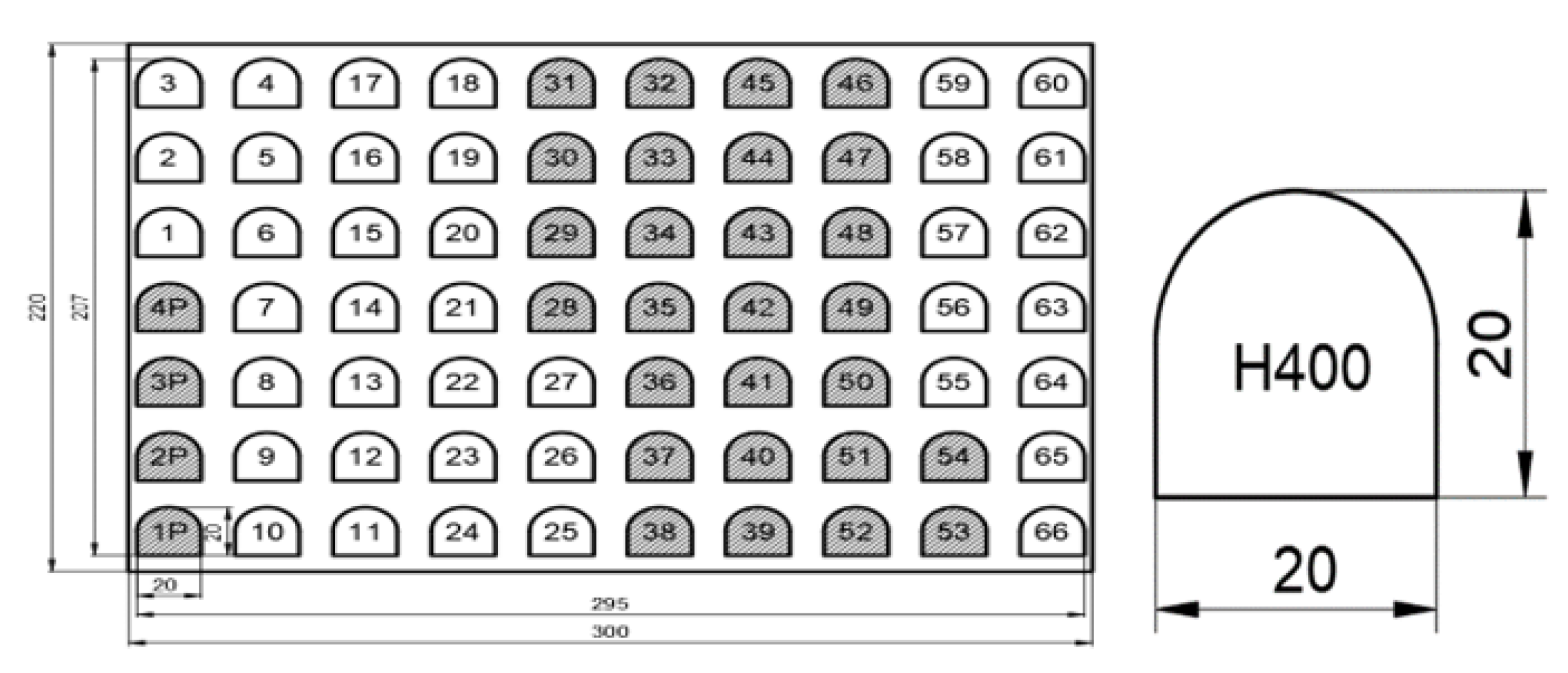
The dimensions of the semi-finished product used in the experiment are 300 mm, 220 mm and 8 mm for length, width and thickness, respectively. The 5.181 kg plate was cut, as shown in
Figure 1, to perform a complete factorial experiment, based on an experimental plan, to determine the optimal value of the input parameters that influence the cutting width.
The factorial design consists of 27 tests, followed by four replicas. There were two semi-finished products containing 135 pieces. Test processing was done to determine the combinations of parameters that provide the least satisfactory results, especially that still ensure cutting. The extreme combinations were tested, and the average values of laser power, gas pressure and cutting speed were chosen. Following the experimental design, design 33 was built which offers all possible combinations of the values of the cutting parameters. The complete factorial plan allows the study of the common influence of the input parameters on the variation of the cutting width. The complete design of the independent test block was established with respect to the single central test point, maintaining a balance of increase and decrease in the values of the independent parameters, resulting in an orthogonal matrix.
The piece with a contour consisting of three straight segments and a circular profile, was designed to be cut to the dimensions: length 20 mm, width 20 mm, with a semi-circular side, from a 20 mm side square, effective area 0.00036 m
2 and mass 0.02803 kg. The sketch of the resulting piece is shown in
Figure 1.
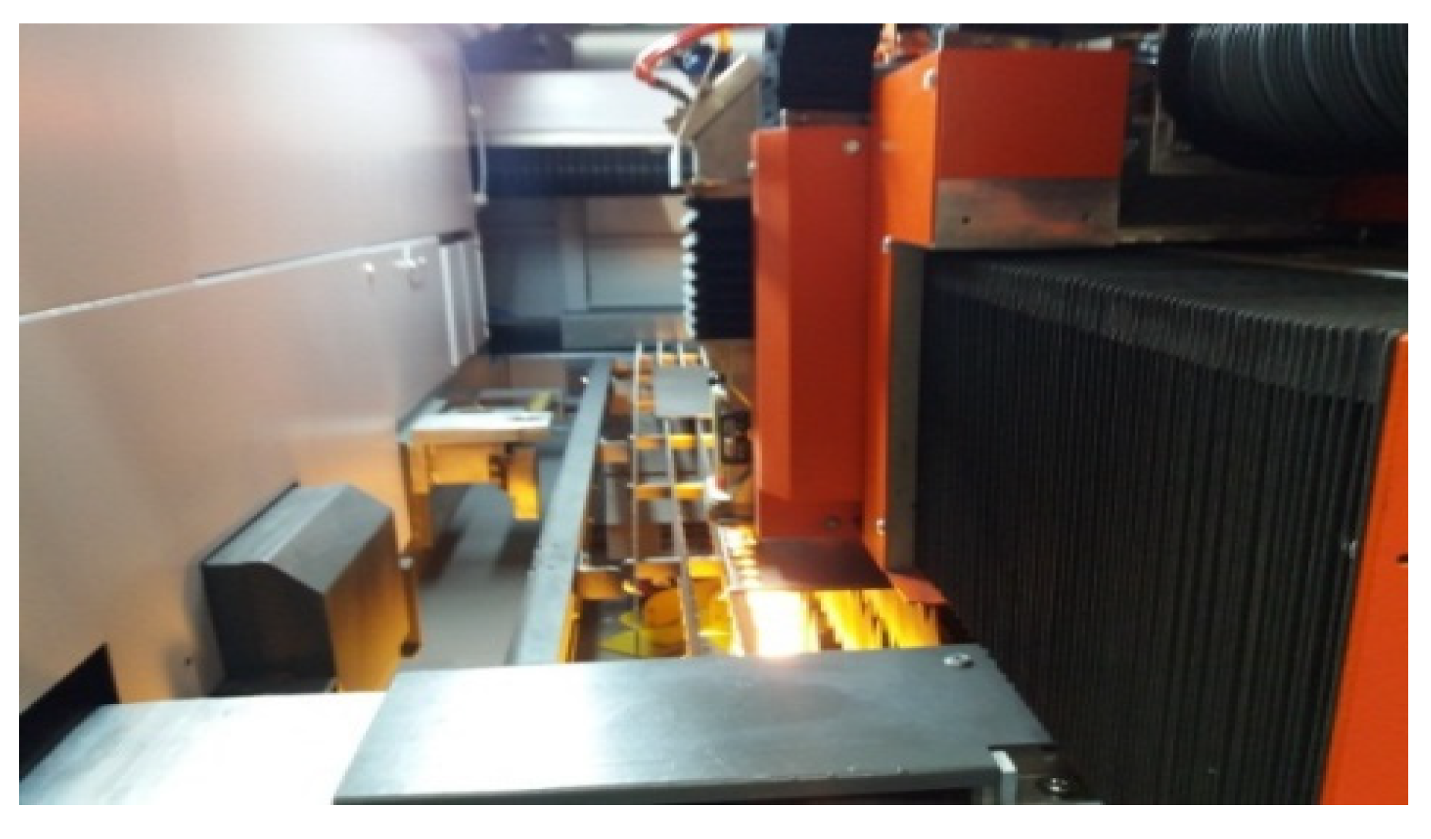
A complete factorial experiment was performed to determine the most suitable combinations that decrease the cutting width and improve the production cost. The ByAutonom 4020/6000 W laser cutting equipment, manufacturer: Bystronic Switzerland, was used to cut H400 sheets (
Figure 2).
The wavelength of the CO2 laser beam is 10.6 µm. The diameter of the laser beam D at the entrance to the lens is 20 mm, and the diameter of the spot is 0.2 mm. The conical nozzle through which the gas is directed has a diameter of 1.5 mm. Starting from the source, the laser beam reaches the lens with focal length of 190.5 mm, and is concentrated in the focus of the lens, where the incident intensity on the piece increases 103–104 times, compared to the value recorded before entering the lens, approximately 162.5 × 10⁵ W/cm2. The focusing position of the laser spot was kept constant at +1 mm above the upper level of the blank, taking into account that the assistant gas is O2.
The research of the influencing factors on the dependent variable, the cutting width, was based on performing preliminary tests to identify the central point, then the cutting experiments were run, the selection of parameters being a condition to obtain correct results. After these tests, the reference values were established: laser power
p = 5000 W, auxiliary gas pressure
p = 0.50 bar and cutting speed v = 1800 mm/min. The factorial experiment has three influencing factors, and each factor has three levels. Compared to the central values, the experiment predicted the variation of the input parameters as follows: laser power ± 100 W, auxiliary gas pressure ± 0.05 bar, cutting speed ± 100 mm/min, so that the levels for laser power reached the values of 4900 W, 5000 W and 5100 W; the auxiliary gas pressure was 0.45, 0.50 and 0.55 bar; the cutting speed was 1700, 1800 and 1900 mm/min. The process parameters of the laser installation are shown in
Table 2.
A mixed experimental design with independently run experiments was prepared with three input levels for laser power, auxiliary gas pressure and cutting speed. The size of the experiment is a block containing 27 independent experiments. You can easily see how the input parameters have been changed. The 27 parts were divided into three series. For each series, a value of the laser power (4900, 5000 and 5100 W) was maintained, while the values of the gas pressure (0.45, 0.50 and 0.55 bar), respectively of the cutting speed (1700, 1800 and 1900 mm/min) were modified.
In the stationary piercing stage (initial piercing of the laser material in pulsed regime) the working parameters are different, compared to those used in the actual experiment, in which dynamic piercing is used. The cutting gas pressure is 0.7 bar, higher than the maximum pressure used in the cutting experiments, and the focusing position f = 0 mm, which means that the laser spot is positioned on the surface of the material. In addition, through a stationary piercing, a conical channel with a diameter larger than the cutting width was drilled. After drilling, the laser entered the straight profile at a distance of about 10 mm until it reached the contour of the part.
In addition to process factors (laser power, auxiliary gas pressure and cutting speed), the cutting width is also influenced by uncontrollable factors: material condition, chemical composition, heat propagated in the material and temperature. The laser beam interacts with the part determining the geometry of the cutting slot. One aspect to consider in the laser beam at the top is that it does not have the same intensity at all points, the distribution being given by the Gaussian curve. The intensity of the oxidation reaction can ensure an improved cutting width. To improve laser cutting, the light rays refracted by the lens meet above the steel material and form the laser spot by interference.
The front inclination of the cut determines the taper in the processing of the parts. The first test piece was 1P, processed as follows: At first a perforated channel with a diameter of 1.07 mm outside the part was created, and after, the laser entered a straight line with a length of 10 mm for processing the first part. Four sample pieces were cut, and subsequently 27 pieces for which the cutting width was measured. An important role in establishing the geometry of the slot and the conical have the cutting fronts created by the laser spot. As the rays leave at an angle of divergence, it follows that the vertical section through the material has the shape of a trapezoid with bases Ks and Ki, whose height is 8 mm. How each process parameter influences the cutting width is analysed using the statistical model of prediction and regression calculation. The laser beam exposed to the material for a long time heats the cutting area, achieving larger cutting widths than usual. The state of sudden heating and cooling of the part determines the appearance of a temperature gradient in the plate.
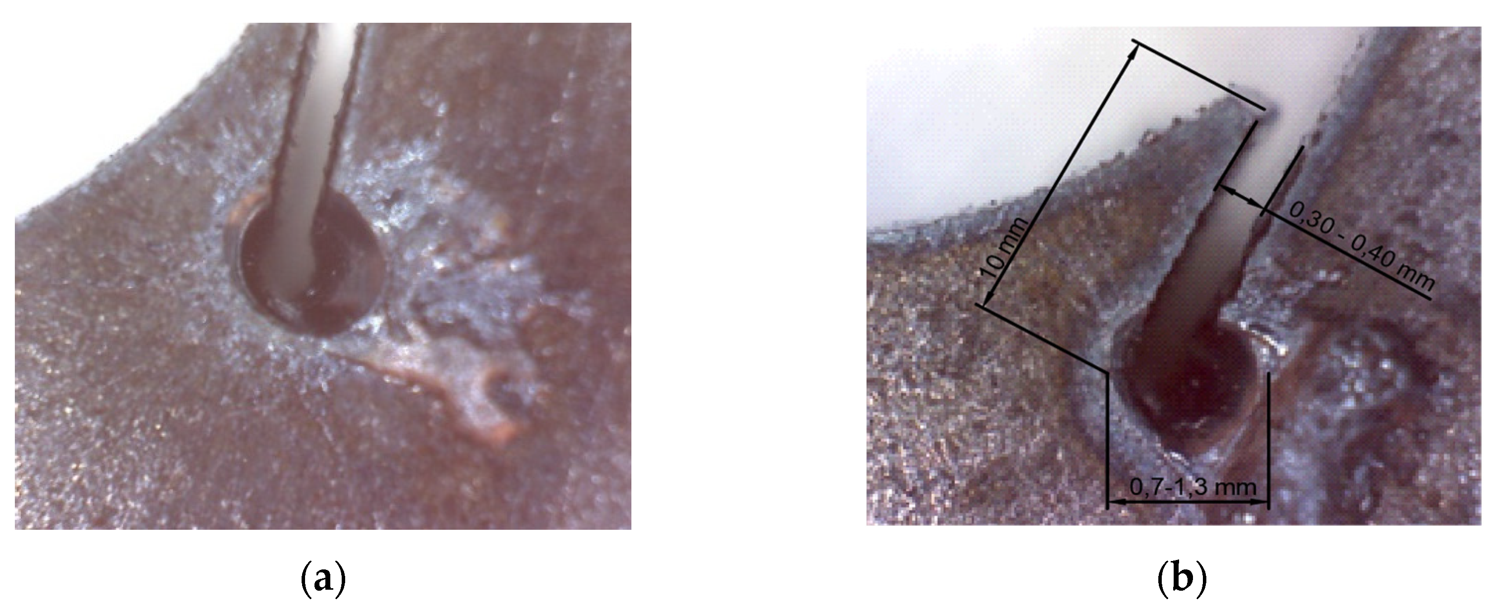
UNIOR 701 caliber (from Unior Tools manufacturer) was used to measure the slit at the straight side. In the experiment it was used to measure the cut through the material by probing, based on the pass-by-pass principle. Laser piercing is the first contact between radiation and material. A conical channel is produced, because the geometry of the laser beam has a conical appearance, while around it the cut edges are burnt by the oxidation reaction. With the help of a Celestron digital microscope, the plate channel was studied for parts 1 and 28 (replica of part 1), in which minimum values of the input parameters were used (
Figure 3a,b).
The shape at the entrance of the channel is a circular surface, surrounded by melt. As the laser penetrates the material, the diameter of the bore decreases. The melt around the channel was removed from the slit at first on the top edge. There is melting on the bottom edge of the metal sheet due to the removal of hot drops on the bottom edge. The material is melted locally and cut due to the focused laser energy.
The spot of the laser beam produces in the material a liquid portion (melt) which is removed with the help of the assistant gas, thus forming the gap between the piece and the waste plate. The melt acquires an approximate spherical shape. Centrifugal, superficial and inertia forces act on the melt. Centrifugal force (Fcf) occurs due to heating and increased thermal agitation of the liquid melt. Surface forces (Fs) act to reduce the potential energy in the surface layer, keeping the melt to a minimum volume. The force of inertia (Fi) occurs as a result of the tendency to increase the liquid volume and the tendency of detachment of small droplets from the melt [
33].
Heat accumulation helps to process the material by laser cutting. H400 steel has increased thermal resistance, reducing heat dissipation, which shows us a giant energy available in the processing area. The high energy density required by laser cutting of Hardox steels means increased energy consumption and thus reduced cutting efficiency and increased processing costs. Mainly the research methods include: CO2 laser is suitable for cutting H400 steels, because the laser beam has a power of over 4 KW with an average and maximum level, good quality and high cutting efficiency; DOE is used in robust experiments of laser cutting; metal sheets and parts are researched to set Kerf to the right profile; the experimental design was run at three levels of cutting parameters resulting in 27 references; the measurement of Kerf responses was done with the slit by probing the slot based on the passing principle/does not pass; and the experimental data were mathematically and statistically processed using the RSM response surfaces given by the linear (L) and quadratic (Q) model.
3. Results
During the study, the cut parts and steel scrap plates were carefully analysed. The followed parameters were cutting width, dimensional accuracy and surface quality. The sequence consisted of checking the plates and the cut parts (surface, thickness and dimensions). The following conclusions were drawn:
The parts have unevenness at the entrance and exit of the laser, places where a portion with wrinkles affected by heat is formed at a distance of up to 3.22 mm, measured from the exit of the contour;
The quality of the cut surface is higher on the semi-circular profile compared to the linear profile. The cut surface has a concave appearance in the middle of the piece;
The surface of the part is damaged at the corners where the laser changes its cutting direction in the area of 90° angles. On the side surfaces, the pieces have unevenness, more accentuated towards the corners. The position of the ridges on the cut surface is vertical and coincides with the direction of the laser beam. Some ridges/striations show bends due to slipping of the melt and resolidification of the surface. On the rectilinear sections of the linear contour of the parts, the surfaces are smooth with small irregularities. The upper part of the cut part has no molten material, which means a good setting of the cutting parameters, except for the area where the laser comes out of the worksheet (the lower part of the piece). This is due to the lower piercing speed of the laser at the exit of the material, which explains the formation of melt on the lower edge of the sheet. For the same reason, another cutting defect was observed on the cut surfaces, in the form of a notch, located between two ridges;
Analysing the stationary piercing on the upper face of the sheet, it results that the largest diameter of the perforation is at piece 8 (3.54 mm), for which the laser power was 4900 W, the assist gas pressure 0.55 bar and the cutting speed 1800 mm/min, while for the rest of the parts the penetration is very small (maximum 1 mm).
Table 3 shows the cutting defects found on the cut parts, the values of the input parameters, and the value of the response of the cutting width, for the 27 pieces of the experimental plan. Parts 9 and 18 are largely affected by steeper and thicker unevenness and penetrations towards the bottom. In all cases, the parts have a small penetration at the lower level, about 0.75 mm. The metal sheet of Hardox expanded in thickness, where the laser acted, due to the heat flow that passes through the material. It has no melt deposited on the bottom edge, which means that the selection of the cutting parameters was correct. Dimensional measurements show differences, from part to part, due to heating, burning and deformation of the plate. The laser attacks the surface, and there is surface damage to the lower corners of the part. Due to the melting of the material, the surface of the part is not perfectly smooth. In the laser input and output areas there are high values of Ra roughness.
In order to obtain finished products with a smooth surface, free of unevenness and roughness, the parts must undergo further mechanical processing to remove the solidified melt. Setting the cutting parameters (laser power, gas pressure, cutting speed) to average values results in a minimum cutting width; 37% of the parts have a minimum cutting width of 0.30 mm. The parts in the third series were made at a temperature of over 100 °C, which led to an increase in cutting width. The evaluation of the cutting width was performed with the Statistics 7.0 program by analysing and interpreting the predictability model and determining the cutting width by the regression analysis method.
The experiment results are:
The parts were processed by laser cutting following the complete experimental factorial design (DOE);
Series 1 of the experiment conducted at minimum laser power, with maximum cutting speed, has a higher cutting width, under the conditions of using the auxiliary gas at average to maximum values;
Series 2 which uses an average power of 5000 W achieves a good cut with a qualitative aspect, without structural defect of the parts. The cutting width reaches the lowest value in six experimental cases. The combination of medium power, low pressure and medium speed indicates the best result of the cutting width. In addition, the average power combined with the average pressure and any value of the cutting speed, indicates a cutting width of 0.30 mm;
If the laser power increases, it causes an increased energy density of the laser beam. The heat absorption in the steel sheet increases and the melt increases its volume, which determines a large cutting width;
Series 3 indicates a generally increased cutting width involving high consumption and costs. The cutting width increases with the evolution of laser power up to 5100 W;
The cutting width decreases if a laser spot with moderate energy is used. This causes a local heat that melts a very small volume of material and after a very short time it dissipates quickly through the material;
If the cutting speed decreases, the time of interaction between the spot and the material increases, having as an effect a longer irradiation of the material, high heat absorption, increased melted volume and finally, the cutting width deteriorates;
If the cutting speed is increased, the spot-part interaction time decreases, resulting in reduced heat absorption of the H400 plate and a decrease in the cutting width;
If low assist gas pressure values are used, the cutting width is affected.
From the calculations, a cutting width of 0.37 mm is obtained, a good result that falls within the limits of the experimental data. Next, the individual influence of laser power and gas pressure on Kerf was studied.
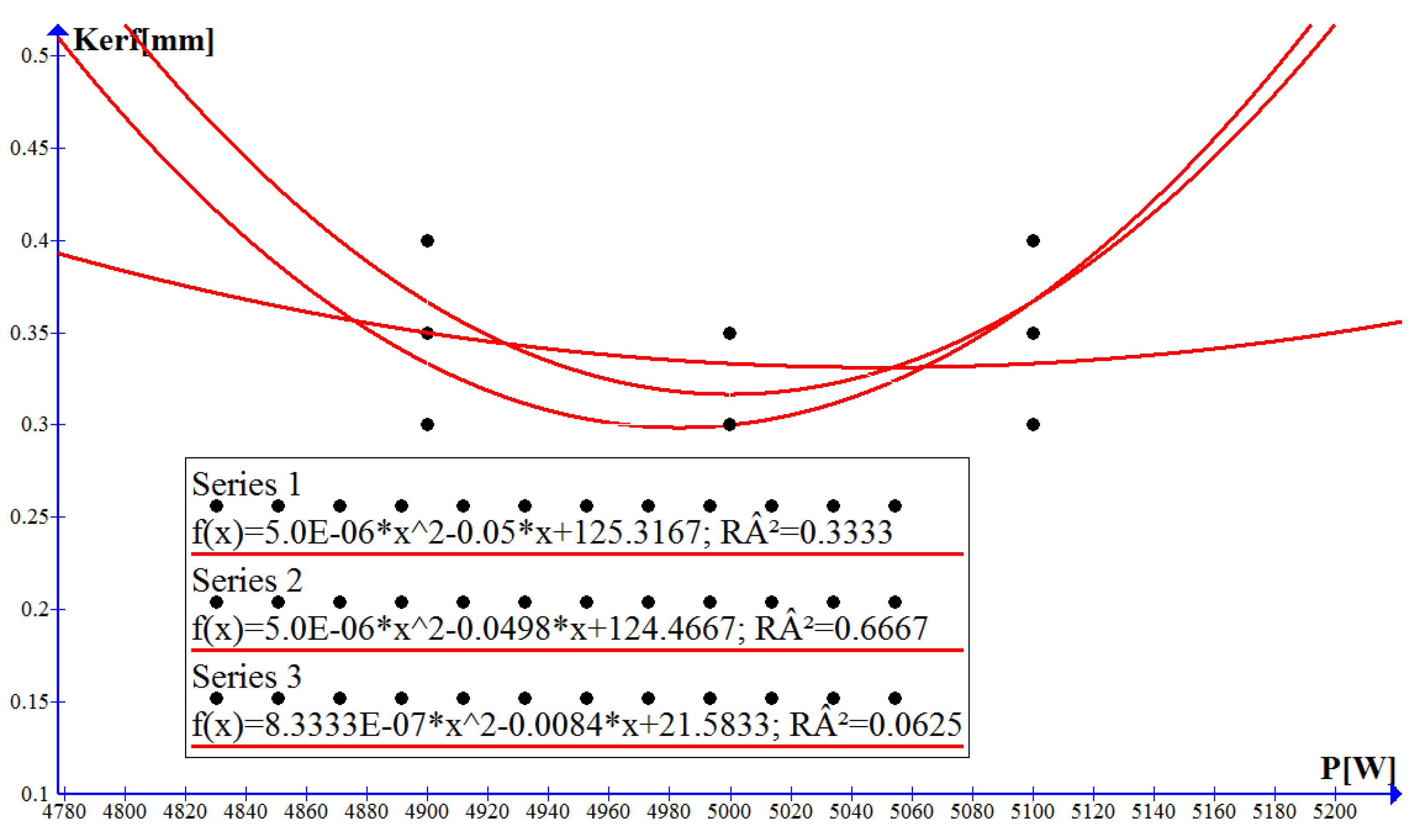
The graphs are built to find the dependence of the cutting width on the laser power. Series 1 was run at 4900 W in three references, 5000 W in three experiments and 5100 W in three cases, at the same time with the low pressure of 0.45 bar kept constant. Nine values for the cutting width resulted. The coefficient of determination R
2 = 0.33 is low. For series 2, the procedure was similar, slightly increasing the gas pressure to 0.50 bar (
Figure 4).
The Pearson coefficient R
2 = 0.66 shows that the cutting width depends on 66% laser power. The functional relationship between the cutting width and the laser power is approximated by the polynomial:
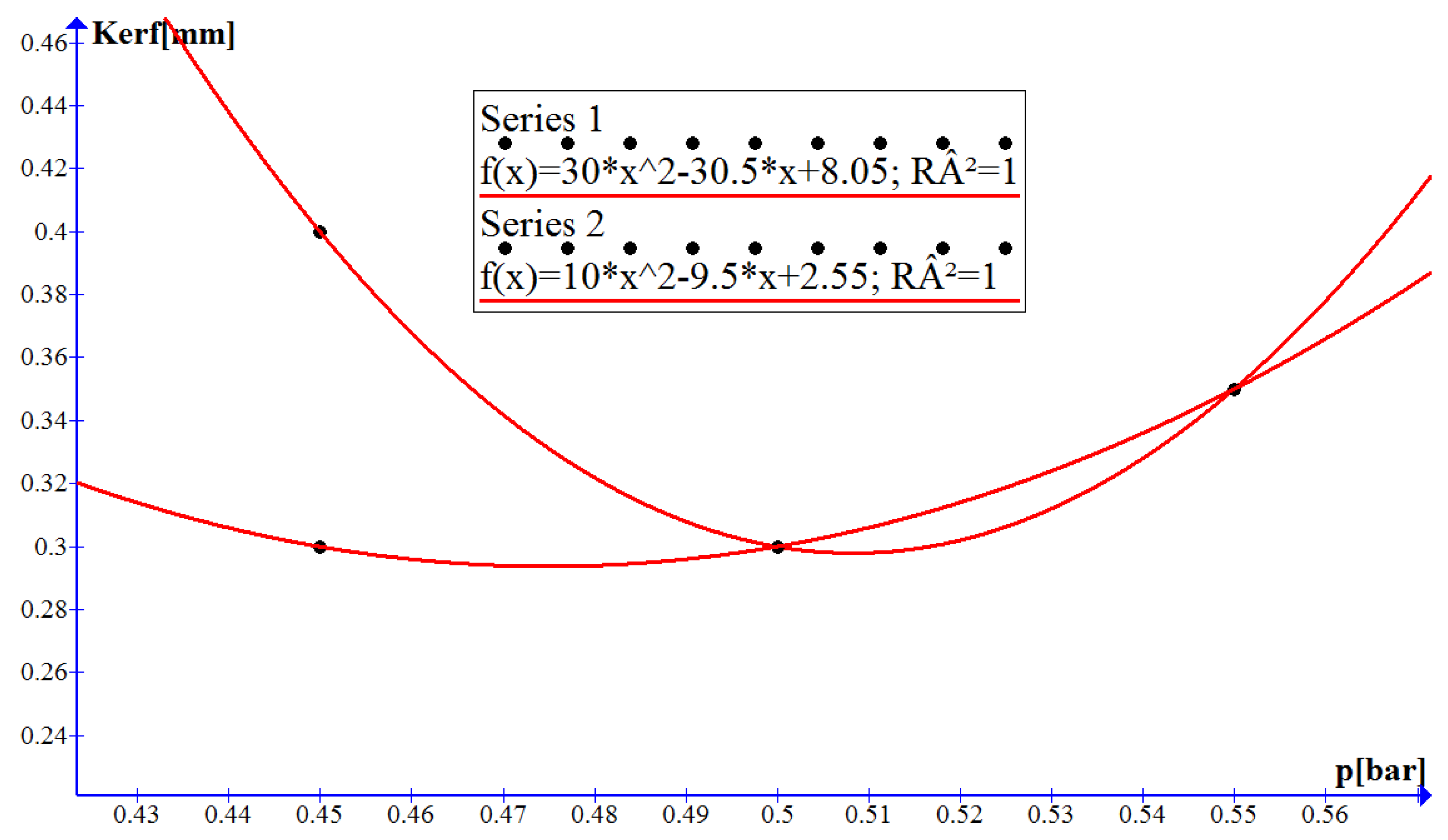
The best dimensions of the slot width are obtained at average values of laser power equal to 5000 W and cutting gas pressure of 0.50 bar. The speed between values of 1800 and 1900 mm/min ensures a better quality of the cut surface, smaller cutting width, if we consider an average laser power level 5000 W, and an average pressure of 0.50 bar. If the pressure is increased to 0.55 bar the results become unsatisfactory. Series 1 was chosen for all minimum levels of the independent parameters (4900 W; 0.45 bar; 1700 mm/min), at the average levels of the cutting parameters (5000 W; 0.50 bar; 1800 mm/min) and at the level of maximum input parameters (5100 W; 0.55 bar; 1900 mm/min). With the help of the Graph 4 program, the dependence of the cutting width was obtained depending on the assistant gas pressure and the functional relationship between them (
Figure 5). The minimum pressure is obtained using Fermat’s theorem and is equal to 0.508 bar. The Karl–Pearson coefficient is equal to 1 which indicates that there is a strong link between the cutting width and the assist gas pressure. The parts manufactured by laser processing are geometrically characterized by a minimum width of 0.30, under the conditions of setting the input parameters at 5000 W, 0.50 bar and 1800 mm/min.
Series 2 was obtained under the following experimental conditions: (5000 W; 1900 mm/min; 0.45 bar), (5000 W; 1900 mm/min; 0.50 bar) and (5000 W; 1900 mm/min; 0.50 bar). Very good cutting widths were obtained for the pressure range (0.47–0.48 bar). The minimum of the function is 0.479 bar characterized by a cutting width of 0.31 mm. The optimal cutting conditions are described by the variation of the cutting width as a function of the auxiliary gas pressure for H400 using the polynomial:
For series 1 (laser power 4900 W), the measurements made on the cutting width highlighted three pieces with 0.30 mm, three pieces with 0.35 mm and three pieces with 0.40 mm. It is observed that under conditions of minimum gas pressure, laser power and speed, a maximum cutting width is obtained, and for the combination of minimum power, maximum pressure and speed a minimum cutting width (0.30 mm) results. Series 2 with pieces numbered from 10 to 18, has six pieces with minimum values of cutting width (0.30 mm), due to preheating of the sheet. Series 3 with parts 19 to 27 has a single piece with a cutting width equal to 0.30 mm (piece 25), because the sheet was heated during previous processing.
We therefore conclude that the parameters used in series 1 and 2 are indicated as a priority in the technological process of cutting in order to have a minimum cutting width, material savings, low energy consumption and implicitly low processing costs.
The input data needed to determine the cost of the laser manufacturing process were centralized in
Table 4, with the prices being of the manufacturers. The study aims to determine the cost of the manufacturing process, which is of interest to manufacturers of such facilities, but especially to users. The first column of the table contains the cost elements identified in the processing. The second column indicates the calculation relationship. All costs were expressed in Euro/hour.
The range of variation of the cutting width allows the evolution of the processing cost between certain limits. The consumptions in the table are specific to the installation used for laser processing.
The analysis of the experiment shows a good arrangement of the block of parts. An important parameter used in cutting is the assist gas pressure. For this reason, an important result is the identification of the function of approximating the cutting width in relation to the oxygen gas pressure. In this case, the dependent variable is the cutting width. The initial function depends on the set of x
i points, according to
Table 5. The values considered were: (4900 W; 0.45 bar; 1700 mm/min), (5000 W; 0.50 bar; 1800 mm/min) and (5100 W; 0.55 bar; 1900 mm/min).
The Lagrange interpolation polynomial that corresponds to a functional relation f in nodes x
0, x
1, x
2 is given by the relation:
The polynomial passes through the points (0.45; 0.40), (0.50; 0.30), (0.55; 0.35) being described by a parabola. The Lagrange interpolation polynomial is obtained from the basic Lagrange polynomials and the value of the function f at points x
i. The mathematical expression has the following form:
The interpolation approximation criterion presents the best possible approximation of the function f(x) by the interpolation polynomial L(x). The interpolation method establishes a functional link between the interpolation support consisting of the assisting gas pressure data set and the cutting width. The estimation error calculated as the difference between the actual function and the Lagrange function is 4.25%.
To calculate the external parameters of the laser beam, it is important to know the radiation strength, spot diameter and optical properties of the material. The physical phenomena that take place following the laser–material interaction are based on the transformation of laser energy into thermal energy. The increase in local temperature and the distribution of laser-induced heat change the thermal state of the metal by heating-melting-vaporization. The intensity of the incident radiation at the moment of penetration in the material is given by the relation:
The intensity of incident radiation entering the material at depth x follows the relation [
35]:
where R is the coefficient of reflexion; A is the absorption coefficient.
The temperature inside the material developed by the absorption of laser radiation is a parameter that indicates the heat input required for heating with phase transformations of the target until melting. The absorption coefficient for metals is 10–15% for the CO
2 laser wavelength of 10.6 µm [
32]. The reflection coefficient depends on the wavelength; in the case of the CO
2 laser it is 0.9. Draganescu et al. indicated that at 0.2% C, the thermal conductivity is 39 W/m*K [
33]. Thus, we obtain the values of the physical quantities studied given in
Table 6.
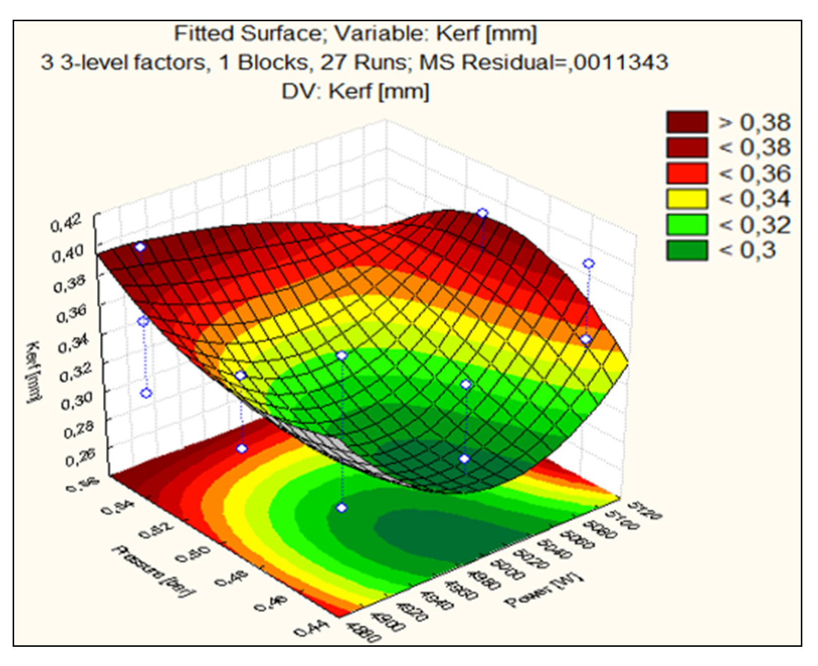
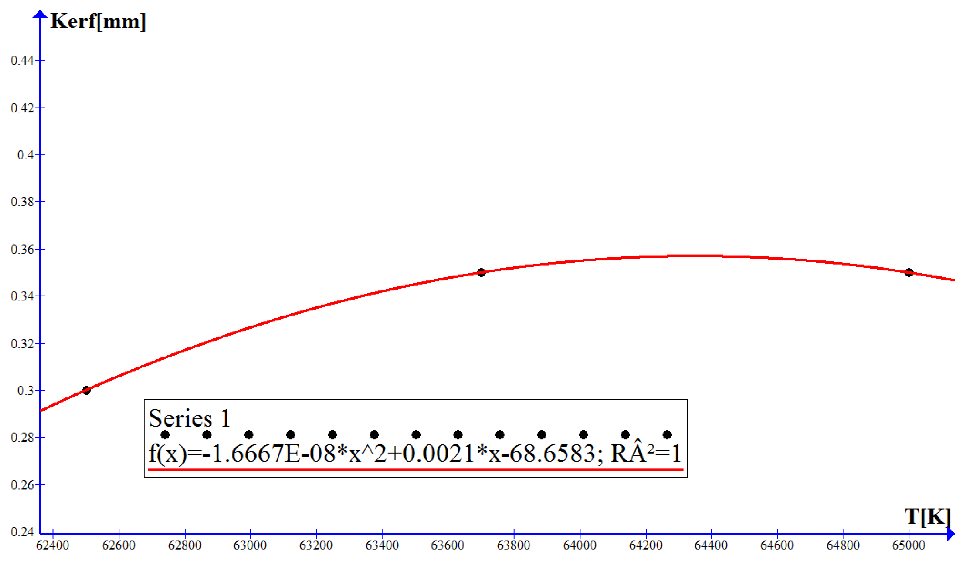
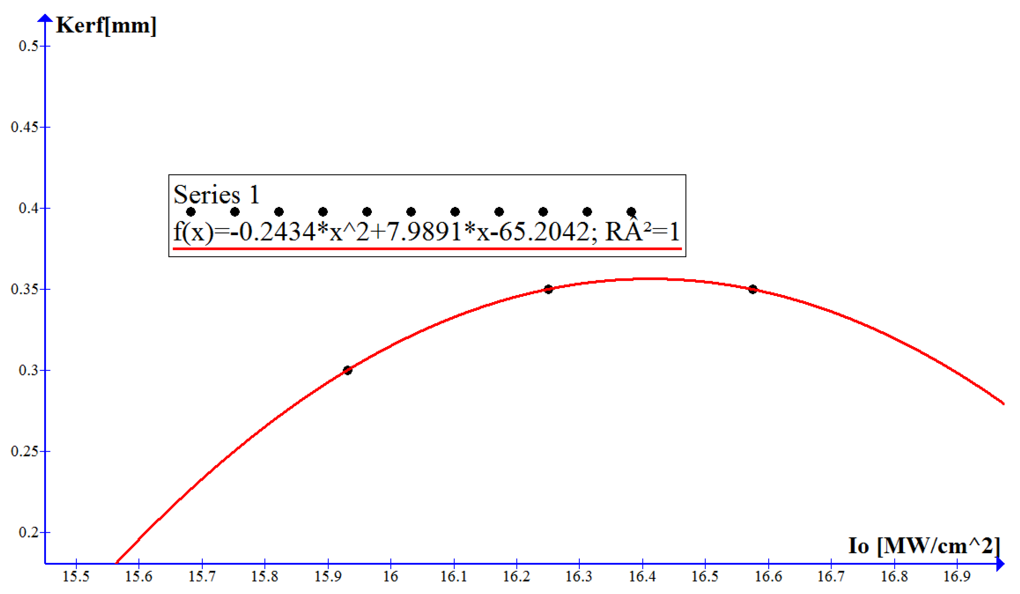
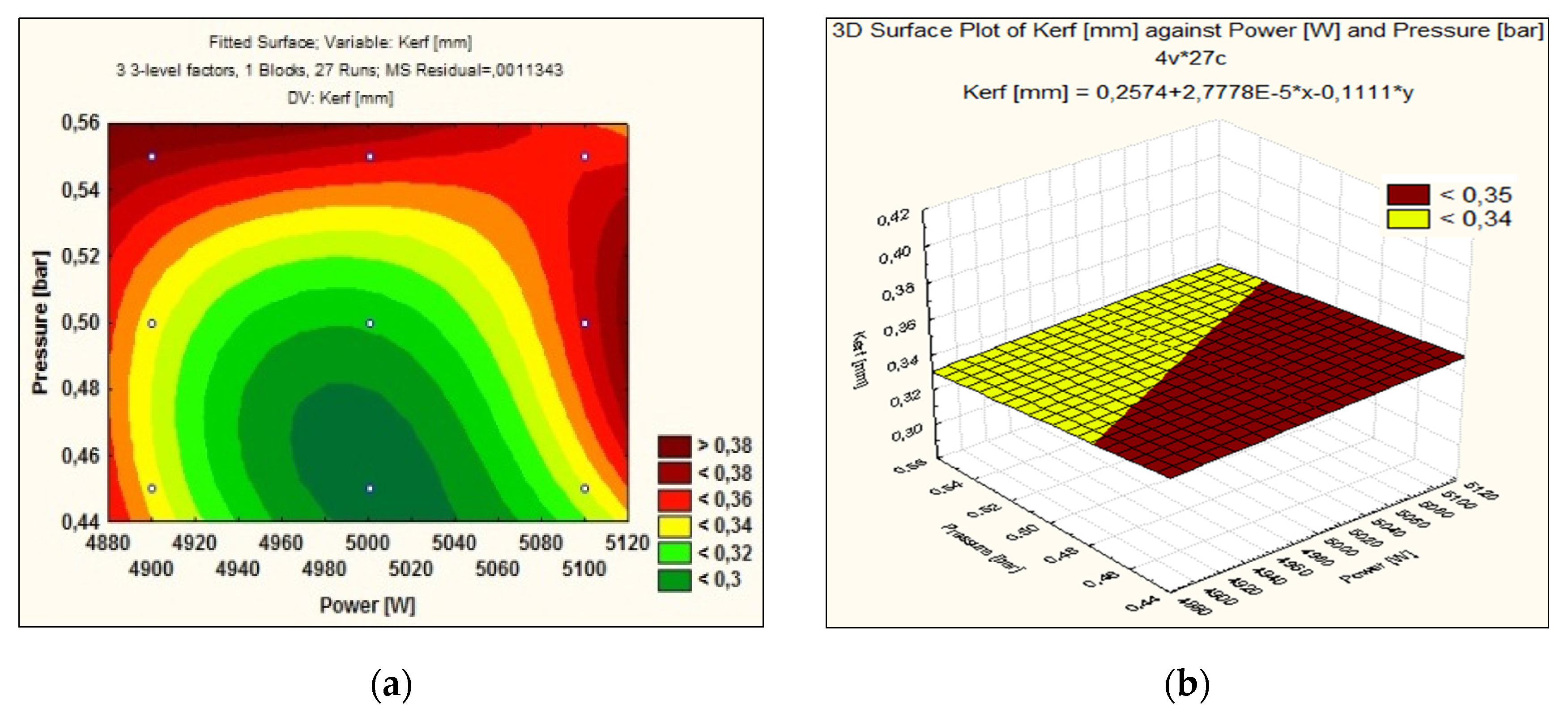
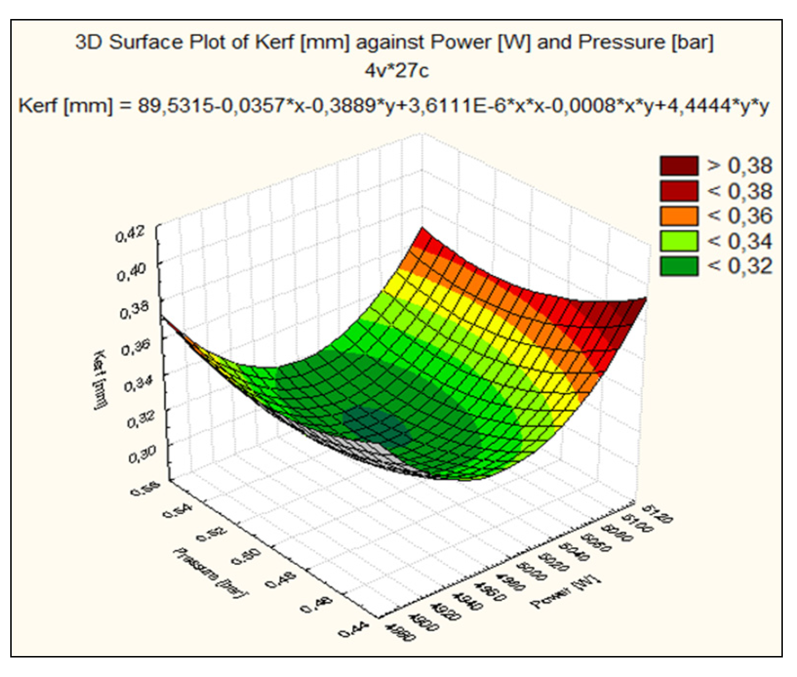
The dimensions of the target are larger in relation to the radius of the laser spot which generates a constant flow of energy while creating cuts of material, delimiting the slot. The cutting width dependence on the temperature and the incident intensity, under conditions of maximizing oxygen gas pressure and cutting speed, for the three levels of laser power used in the experiment are shown in
Figure 6 and
Figure 7.
The quadratic regression model of the cutting width as a function of the temperature produced by the laser in the material has the form:
The quadratic regression model of the cutting width as a function of the incident intensity produced by the laser radiation at the entrance to the material has the expression:
The second-order model of quadratic regression was developed for the cutting width by accessing data from independent experiments. The coefficient of determination R2 was calculated to verify that the data anticipated by the regression model are appropriate. When using the Graph program, the coefficient of determination is 1, which means that the mathematical accuracy of the regression is the most appropriate. When the temperature and power density increase, an increase in the cutting width is observed. The cutting width decreases as the temperature in the material and the incident intensity decrease.
If the laser power increases, the cutting width is disturbed due to the energy density. The situation leads to a longer interaction time between the laser radiation and the substance, and the slit increases due to thermal erosion. Specifically, the cutting efficiency of the laser beam decreases with the increase of energy received from the laser, due to losses through thermal conduction. Kerf was evaluated, and the results show a section of the slit as a V-profile, almost straight edges, parallel or A-shaped. In most cases, the top width is larger compared to its size at the bottom edge. Moreover, a sufficient amount of laser energy is absorbed more intensely at the upper edge of the Kerf profile. This energy is transformed into heat, thermal energy that melts a very small portion of the material locally, strongly heats the cut surfaces by changing the metallographic structure of the surfaces, the local change of the material characteristics. The local heat generated in the material, in the area affected by the laser, can trigger chemical reactions very quickly. As a result of the thermal action of the laser and the chemical reaction under the influence of an oxygen jet, changes in the size of the cutting width occur, so that at the lower edge of the material, an increased Kerf results due to burning and melting of cut material. In the process of interaction of laser radiation with the substance there is a temperature gradient through the cut that determines the heat in the slot.
The diffusion of heat through the sheet is based on the fact that, under the influence of the laser pulse, the optical energy is instantly transformed into heat. The incident intensity of the laser beam decreases as it enters the material. The gradient of laser radiation intensity can be explained by the fact that the material is resistant, the layers of molten material have different temperatures and the accumulated heat is removed from the slit more difficultly. The temperature difference between the two surfaces of the plate explains that the melt loses mass as it discharges to the bottom edge. The range of variation of the radiation intensity has a higher temperature of the molten area on the surface of the material, and a lower temperature on the lower surface of the steel plate, resulting in a smaller melting area.
In this study, the cutting width was determined as a function of laser power, gas pressure, material temperature and the incident intensity of laser radiation. The measured results are represented graphically in
Figure 3 and
Figure 4 showing a low Kerf at values close to 5000 W and gas pressures in the range of 0.47–0.48 bar. As can be seen from
Figure 5 and
Figure 6, in the case of the assisting gas pressure of 0.55 bar and a speed of 1900 mm/min, Kerf is the lowest. The same result happens at a temperature of 6.25 × 10
4 K and a minimum incident intensity of 15.931 × 10
6 W/cm
2. The Kerf cutting width compared to the laser power, the assisting gas pressure, the working temperature and the incident intensity for the H400 sheet with a thickness of 8 mm has a square shape. These curves have a maximum for Kerf processing at oxygen gas pressures and cutting speed under maximizing conditions and a minimum that was reached at selected cutting pressures and inputs at average values. The average cost is for the CO
2 laser installation applied to the 8 mm sheet for H400 at the value of 13.245 Euro/h. The function of approximating the cutting width according to the important cutting parameter, the low pressure of the assistant gas, run at three levels used in the experiment (0.45, 0.50, 0.55) bar is a Lagrange polynomial of quadratic order. The channel/cut is well formed during the O
2 laser cutting of the steel when the input parameters are set to medium values and low power densities that cause lower surface and material temperatures, the important role being played by the minimum thermal energy that forms melt of minimal geometric dimensions and moving on the side walls along the cutting front. The evaluation of the influence of the input factors, laser power and gas pressure, but also of the physical quantities detached from the laser melting on the slit showed that under laser processing conditions, the distribution of these inlets in the slot have different parabolic shapes. The interaction between the input factors can create a minimal melt that removed from the slot will ensure a small cutting width between the piece and the sheet. There is a good agreement between the experimental model and the calculated one of the assistant gas pressure.


