Review

A Review of the Performance of Infilled RC Structures in Recent Earthquakes

1
CONSTRUCT-LESE, Department of Civil Engineering, Faculty of Engineering, University of Porto, 4150-003 Porto, Portugal
2
RISCO, Department of Civil Engineering, Universidade de Aveiro, 3810-193 Aveiro, Portugal
*
Authors to whom correspondence should be addressed.
Appl. Sci. 2021, 11(13), 5889; https://doi.org/10.3390/app11135889
Submission received: 3 June 2021 / Revised: 19 June 2021 / Accepted: 21 June 2021 / Published: 24 June 2021

Abstract

:
The primary objective is to present the most representative types of damage observed in reinforced concrete (RC) structures due to earthquakes. Those damages are divided according to the ten most representative types. Examples and the main reasons that could trigger each failure mechanism are presented. The definition of these damage types is supported by post-earthquake damage reconnaissance missions in Sichuan (China) in 2008, L’Aquila (Italy) in 2009, Lorca (Spain) in 2011, Emilia-Romagna (Italy) in 2012, Gorkha (Nepal) in 2015, Muisne (Ecuador) in 2016 and Chiapas (Mexico) in 2017. An extensive discussion is presented concerning the infill walls’ seismic behaviour and their interaction with the RC structural elements. The presentation of the significant learnings and findings concerning the typical damage herein presented and discussed are compared with the common Southern European construction practice. The impact of the infill walls on the rehabilitation costs of damaged RC buildings is also studied. These costs are compared to those related to the structural damage and rehabilitation of the entire building structure to understand the impact of the infill walls. Finally, a case study is presented to study the effect of implementing simplified retrofitting strategies to prevent the soft-storey mechanism, one of the most common problems observed in past earthquake events.

1. Introduction

Observations on the performance of buildings during low, medium and strong earthquakes have served to increase the knowledge concerning the buildings seismic behaviour and specifically to identify proper and improper constructions and earthquake load-resisting systems. Design procedures have been developed in regions that have been inhabited, which are subjected to relatively frequent earthquakes, resulting in reasonably good seismic performances [1]. Although such design procedures are not universally applicable due to regional differences, structural engineers can learn by studying those procedures in terms of construction materials and techniques. Apart from that, the post-earthquake damage reconnaissance reports highlighted the importance of the masonry infill walls in the seismic performance of the reinforced concrete (RC) building structures. Luca et al. [2] pointed out that these elements, usually called ‘non-structural’ elements by the structural design codes, may play an essential role in structural behaviour and are responsible for a significant part of the human, material and economic losses, as proved in the Lorca earthquake in 2011 [3]. The same observation was made in 2016 by Masi et al. [4], when a Mw 6.0 earthquake occurred in Central Italy, causing severe damages to infilled RC structures [5].
The RC structures behaviour depends on the structural elements’ stiffness, strength, ductility and energy-dissipation characteristics, among other factors [6]. The building structural strength is provided by each structural member and the interaction and connection between them [7]. Since the buildings are structures with a high degree of redundancy, their response is controlled by the loading redistribution capacity, which can fail if some of the members reach the failure and the remaining ones cannot accommodate significant deformations before failure. The insufficient strength capacity of some structural members can be justified by being subjected to seismic loading demands significantly higher than the values considered during their design process.
The structures should be designed according to the expected seismic demands prescribed by the modern codes to ensure adequate stiffness, strength and ductility to the elements and, consequently, the global structure. The seismic design of RC structures needs to be performed by considering the RC structural elements and secondary elements and non-structural elements like the masonry infill walls. Some international codes like Eurocode 8 [8] consider the infill panels as non-structural elements and provide low importance to their seismic behaviour and participation in the response of the building. Their contribution to the seismic structure response is usually disregarded. The Nepalese earthquake in 2015 evidenced that the infill walls often play an essential role in the seismic response of the RC structures [9]. They provide an increment of stiffness, strength, and energy dissipation to the global structure. They change the natural periods and vibration modes of structures, attracting higher seismic loadings than those expected during the design process [6]. Nevertheless, their in-plan and in-elevation distribution can also affect negatively the global structural response [10]. The infills walls presence reduce the building deformation capacity and can potentiate failure mechanisms that the structural members were not designed to support [11].
This manuscript aims to present the most representative types of damage observed in infilled RC structures due to earthquakes. Those damages are divided according to the ten most representative types. The main reasons that could trigger each damage type are presented. A detailed discussion is presented concerning the infill walls seismic behaviour and their interaction with the RC structures.
The definition of the most common damage types herein presented is supported by several post-earthquake damage reconnaissance missions carried out by different researchers from the Laboratory for Earthquake and Structural Engineering (LESE) of the University of Porto. The list of countries visited post-earthquake include: Sichuan (China) in 2008, L’Aquila (Italy) in 2009, Lorca (Spain) in 2011, Emilia-Romagna (Italy) in 2012, Gorkha (Nepal) in 2015, Muisne (Ecuador) in 2016 and Chiapas (Mexico) in 2017 (see Figure 1). Furthermore, the lessons learned from all these earthquakes are presented and discussed. Finally, the types of damage found are compared with the standard construction practice in Southern European countries.
Retrofitting strategies to eliminate or prevent these types of damages are also presented and discussed throughout the manuscript. In addition, the repair costs of damaged buildings after earthquakes and the impact of the infill walls on the global costs are presented. For this, the rehabilitation costs of the entire damaged building structure are compared with the costs of rehabilitating the damaged masonry infill walls. The last goal of this manuscript is to present a case study to assess the effect of applying simplified retrofitting strategies to prevent the soft-storey mechanism, which is one of the most common problems observed in all the past earthquake events. An eight-storey infilled RC structure was simulated in the software SeismoStruct [12]. Four retrofitting strategies are tested: RC jacketing, the addition of RC shear walls, the addition of steel braces with and without energy-dissipation devices.

2. Seismic Behaviour of Infilled RC Structures: Definition of Damage Type

The Eurocode 8 [8] classifies the structural elements as structural or non-structural. The structural elements are subdivided as primary members (SP) or secondary members (SS). The primary members (SP) are considered part of the structural system that resists the seismic demands, which are modelled in the analysis for the seismic design situation and are fully designed and detailed for earthquake resistance. On the other hand, the secondary elements are not considered part of the seismic resisting system and whose strength and stiffness against seismic actions are neglected. They are not required to satisfy all Eurocode 8 [8] requirements but are designed and detailed to maintain the support of gravity loads when subjected to the displacements caused by the seismic actions.
The non-structural elements (NS) comprise architectural, mechanical or electrical components, systems and components, which, whether due to lack of strength or the way they are connected to the structure, are not considered in the seismic design as load-carrying elements. As mentioned before, the Eurocode 8 [8] recognises that infill panels are included in this NS elements group.
Following the last major earthquakes all over the world, different types of damage have occurred (the most representative ones listed above) and affected the RC structures according to post-earthquake survey damage assessments:
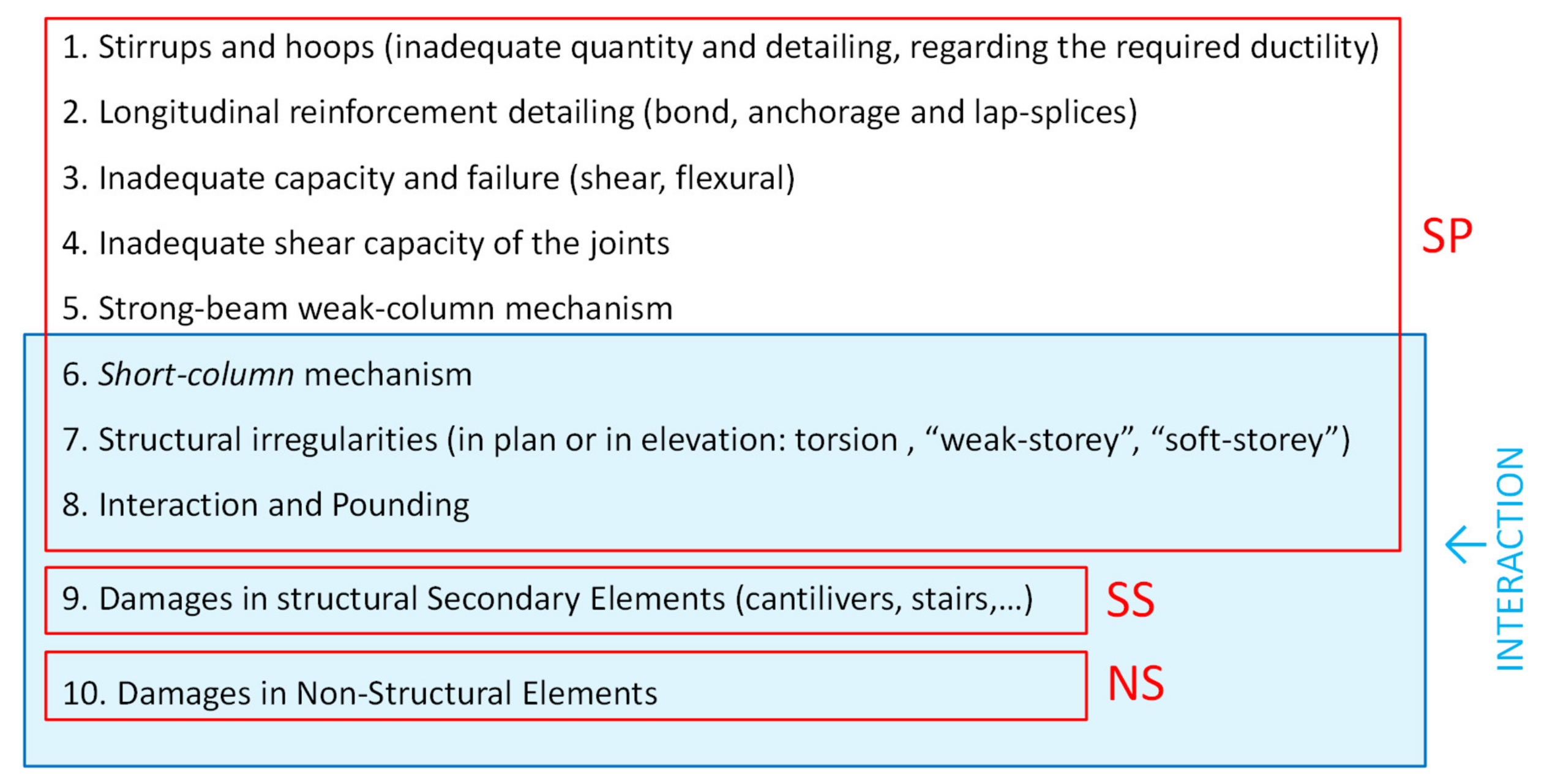
Damage Type 1: Damage associated with stirrups and hoops (inadequate quantity and detailing, regarding the required ductility);
Damage Type 2: Damage associated with longitudinal reinforcement detailing (bond, anchorage and lap-splices);
Damage Type 3: Damage associated with the shear and flexural capacity of elements;
Damage Type 4: Damage associated with the inadequate shear capacity of structural joints;
Damage Type 5: Damage associated with strong-beam weak-column mechanism;
Damage Type 6: Damage associated with short-column mechanism;
Damage Type 7: Damage associated with structural irregularities (in plan and/or in elevation: torsion, ‘weak-storey’ and ‘soft-storey’);
Damage Type 8: Damage associated with pounding;
Damage Type 9: Damage in secondary elements (cantilevers, stairs, etc.,).
Damage Type 10: Damage in non-structural elements.
The first eight damage types are related to the SP members, the ninth is related to SS members and finally, the tenth is associated with the infill walls (NS elements). According to the post-earthquake damage survey assessment, it can be concluded that there is an interaction among the last five types of damage. Figure 2 and Figure 3 show the schematic layout concerning the damage type and their respective interaction. The damage observed in the different post-earthquake field trips highlighted that the masonry infill walls cannot be considered non-structural or secondary elements and disregarded from the expected building seismic behaviour. According to the observations detailed in the following sub-section, the infill walls assume a principal role since they can modify the global structural behaviour.
The following sub-sections detail some examples of each damage type presented and the significant observations and conclusions extracted from the post-earthquake damage reconnaissance missions.

2.1. Representative Damage Type Observed in RC Buildings Due to Earthquakes

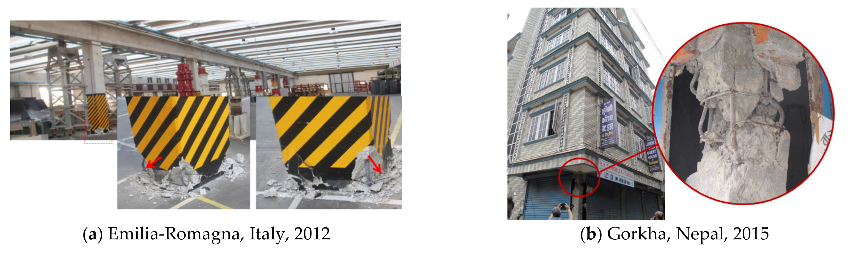
2.1.1. Damage Type 1: Damage Associated with Stirrups and Hoops (RC Detailing)

The philosophy behind the confinement effect is more straightforward and better understandable by all the scientific and professional community. When the concrete is subjected to high compressive loadings, a fragile crushing occurs along the principal compression loading direction. The confinement provided by the stirrups prevents, or at least delays, the concrete detachment. The concrete strength and especially the ductility also improves considerably. The confinement effect depends on the stirrup diameter, the stirrups spacing, the longitudinal reinforcement, the steel quality and the shape of the stirrups [13].
According to the Eurocode 8 recommendations regarding the stirrups folding (135°), the execution of the stirrups folding is frequently overlooked, resulting in their poor efficiency and, particularly, in the stirrups failure during the seismic event.
It is possible to find some examples of RC building structures that, during an earthquake, suffered damage in their RC columns due to inadequate transverse reinforcement, namely poor detailing and designing. Figure 4 shows examples of damage observed following the Gorkha, Emilia-Romagna and L’Aquila earthquakes [9,14,15].
It is recommended adequate confinement of the concrete core of the columns and beams in the plastic hinge regions to prevent strength degradation or fragile failure due to shear and flexural demands and increased ductility. This need for confinement is even higher when the column is subjected to high axial and shear loadings. During an earthquake, the failure of beams and beam-column joints is usually related to the inadequate use of transverse reinforcement and confinement. These failures are commonly observed at a local level and may not result in the total collapse of the building structure. A ductile behaviour can be achieved if a proper and adequate seismic design is carried out, with appropriate transverse reinforcement and detailing. Without a refined design and detailing of the transverse reinforcement, a fragile behaviour can occur during an earthquake, and the probability of occurring columns’ failure is higher.

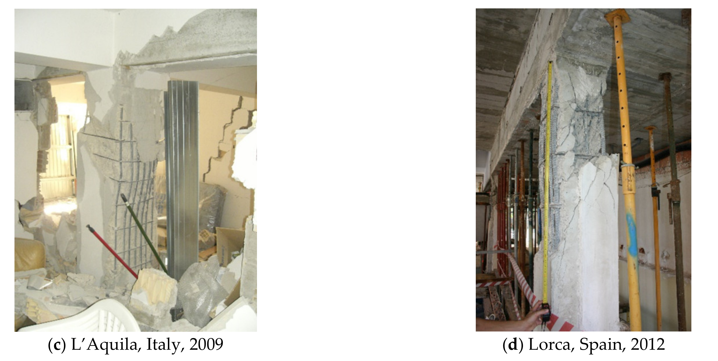
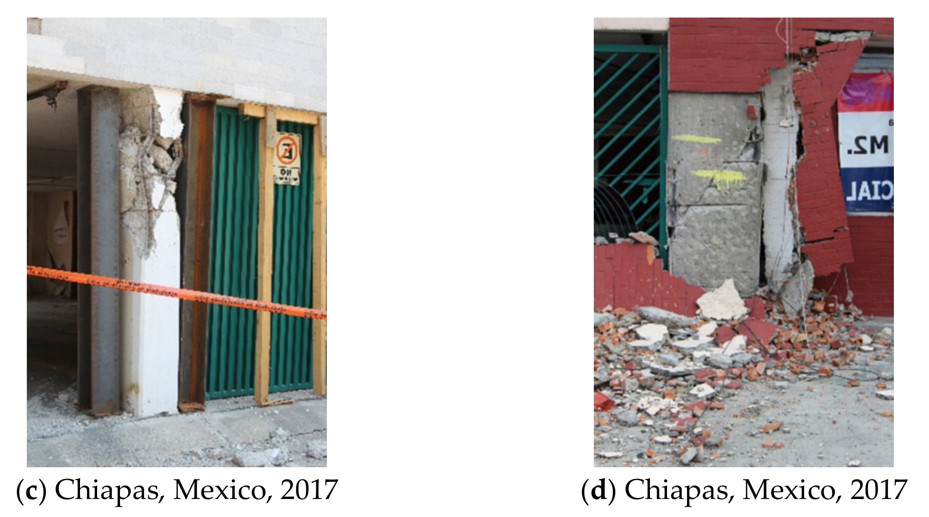
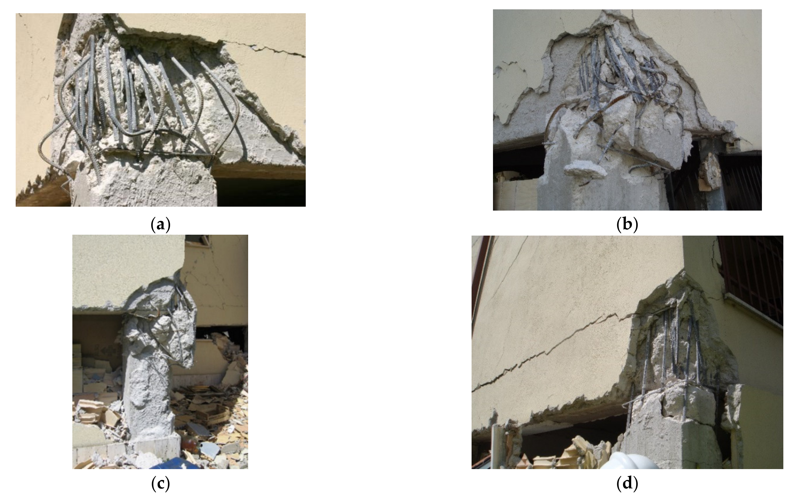
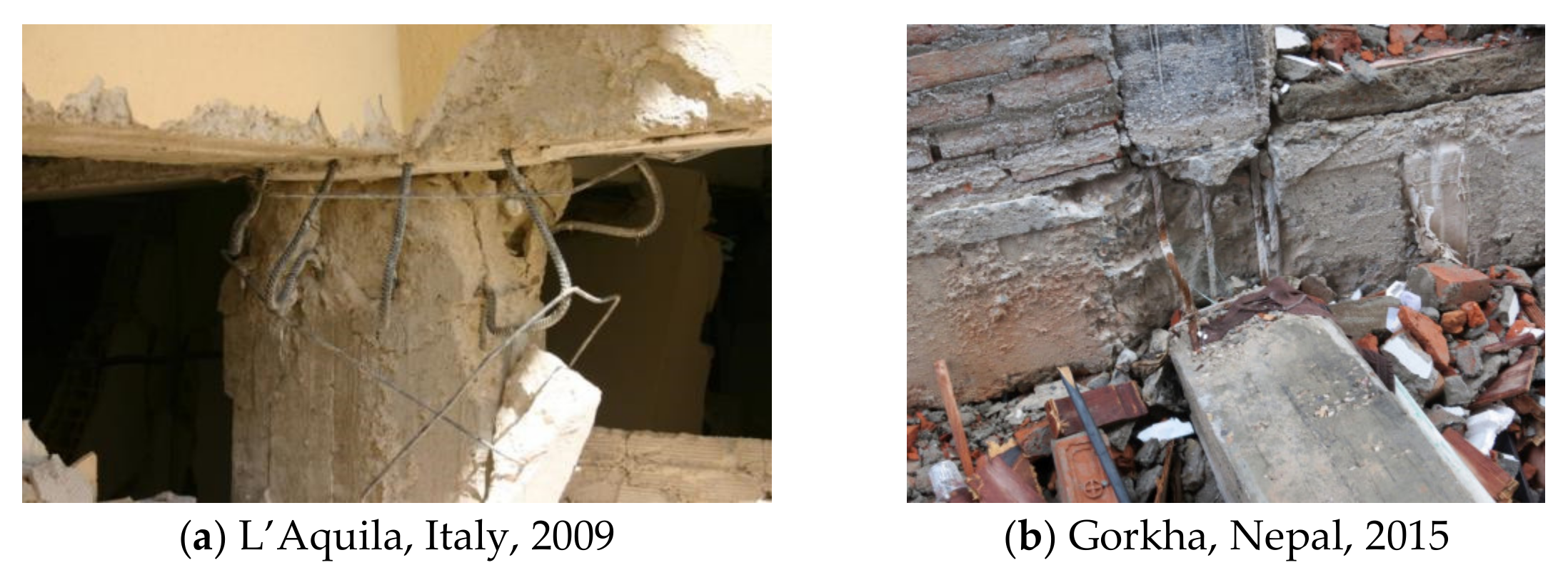
2.1.2. Damage Type 2: Damage Associated with Longitudinal Reinforcement Detailing (Bond, Anchorage and Lap Splices)

The correct and adequate design of the connection allows the concrete and steel reinforcement to form a composite structure. The effectiveness of this connection is fundamental under cyclic loads and when smooth bars are adopted in old existent structures. However, in the case of new constructions designed according to Eurocode 2 [16] and Eurocode 8 [8], the use of smooth bars is not specified.
Some of the basic rules/procedures during the detailing/designing stage to ensure better performance of the reinforcement bond and anchorage are listed below:
Splices and anchorage in regions where it is expectable that the occurrence of cracking of the surrounding concrete (plastic hinge length) should be avoided;
Concrete with anchorages and embedded splices should be well confined to prevent the concrete expulsion;
Compression in the transverse direction to the reinforcement bond positively affects and prevents the concrete expulsion.
Some examples of this type of damage are shown in Figure 5. They are reported due to poor and inadequate detailing of the longitudinal and transverse reinforcement and to the use of smooth bars.
Some experimental studies were carried out on evaluating and retrofitting existing RC building structures designed according to codes earlier than the 1970s [6,17,18,19,20]. Most of these studies are related to ribbed bars. However, only a minor number of research works were developed using smooth bars [21,22,23,24,25,26]. The major conclusions from those works indicate that the strength capacity of the elements built with smooth bars is lower, followed by a more substantial degradation of the connection conditions along the longitudinal bars that significantly exceed and violate the plane sections theory. Furthermore, in most cases, their performance was characterised by a flexural behaviour followed by post-peak degradation, which was confirmed by the measurement of bar strains relatively lower than the steel yielding strain. This fact suggests that the code approach and the procedure to adopt in the seismic safety assessment to estimate the flexural strength capacity overestimate the actual flexural strength capacity of the RC elements (when executed with smooth bars).

2.1.3. Damage Type 3: Damage Associated with Shear and Flexural Capacity of Elements

In areas of moderate/high seismic activity, the structural design for gravity and wind loads usually results in an insufficient shear design, resulting in strength capacities lower than the forces that the element is subjected to during the earthquakes. Furthermore, the current seismic design procedures suggested by Eurocode 8 [8] are based on the ductility concept. Thus, the shear limit (brittle failure) states must be avoided in seismic-resistant structures. For that, the shear demand needs to be limited, or the shear strength capacity needs to be improved. The shear requirements are controlled through design procedures according to the capacity design approach. Since the introduction of the capacity design philosophy, many designers still did not adopt this strategy. Some countries do not have modern seismic design codes like Eurocode 8 [8]. Some countries are only demanding standard guidelines for designing and constructing typical building structures.
Consequently, many existing structures are not correctly designed and present low shear strength capacity. Therefore, one of the most common failure modes observed over the last earthquakes is the structural elements’ shear failure. The designers adopted global safety factors that reduce the seismic loadings, which affects the flexural forces (ductile behaviour) and the shear ones (fragile behaviour) equally. Subsequently, the shear strength capacity is reached before the yielding starts, so the energy dissipation is restrained.
The following strategies need to be respected to improve the shear strength capacity, namely:
Definition of the proper amount of stirrups and respective detailing (according to recommendations like those of Eurocode 8 or other up-to-date codes) to improve the strut mechanism;
Use of enough transverse reinforcement to ensure the concrete integrity and improvement of the aggregate interconnection;
Avoid the combination of tensile plus shear loading;
Use of concrete with better quality;
Use of diagonal bars to prevent the shear/sliding failure in deep elements.
The shear strength and confinement problems are prevalent in corner columns, especially if the building structure has eccentricity between the mass and stiffness centres. The corner columns should be designed with the highest confinement requirements. Figure 6a,b shows examples of damaged columns after the L’Aquila and Chiapas earthquakes, respectively.
Nowadays, the seismic design relies on achieving a ductile behaviour for the structural elements (e.g., columns and beams). This ductile behaviour can be ensured if some necessary procedures are satisfied. The main goal is to prevent the fragile concrete crushing from occurring before the yielding onset in the tensile reinforcement. With this aim, the strategy can be:
Limitation of the axial loading or assuming an increase of the cross-section area;
Limitation of the tensile reinforcement area. The force in the reinforcement should be balanced with the compression forces (and the external axial load);
The element’s capacity under compression should be improved by using concrete with better quality, compressive reinforcement and adequate confinement.
Traditionally, the focus of the designers was related to the structural elements strength and rarely with their ductility. Therefore some of these principles have not been adequately understood and applied. Due to that, some fragile failures were observed in elements subjected to flexural loadings (particularly parts from old existent buildings), as shown in Figure 6c,d.

2.1.4. Damage Type 4: Damage Associated with the Inadequate Shear Capacity of the Structural Joints

The beam-column joints can be subjected to a significant stiffness reduction due to the insufficient shear strength, poor and inadequate reinforcement anchorage. Both types of failure are related to the deficient use of transverse reinforcement and the poor detailing of the reinforcement anchorage through the joint. The collapse or extensive damage observed in buildings’ structures due to the absence of good beam-column joints is widespread during an earthquake event. For example, Figure 7 presents beam-column joints with poor detailing that resulted in the building’s collapse during the L’Aquila earthquake in 2009.

2.1.5. Damage Type 5: Damage Associated with the Strong-Beam Weak-Column Mechanism

The current codes include structural detailing procedures to improve the building’s seismic performance and repair strategies for a post-earthquake scenario. The plastic hinges development hierarchy should be defined in the design phase to achieve an energy-dissipation mechanism. Accordingly, it is widely accepted that the critical location for the plastic hinges occurrence is located at the beams and columns extremities when dominated by flexure [27]. Therefore, the modern seismic codes recommend ensuring ductile moment-resistant frame structures and inelastic actions in the beams (through the control of the damage location and inter-storey drifts) to reach a weak beam-strong column mechanism. Thus, the capacity of the column in each joint must be higher than the beam capacity. Typically, the existing RC moment frame structures were designed without this concern since they were built before the actual seismic codes.
Many RC structures collapsed or were severely damaged due to the development of the strong beam–weak column mechanism, confirming the importance of the recommendation of the actual codes. Figure 8 shows examples of buildings severely damaged due to strong beam-weak column mechanism after the L’Aquila and Gorkha earthquake.

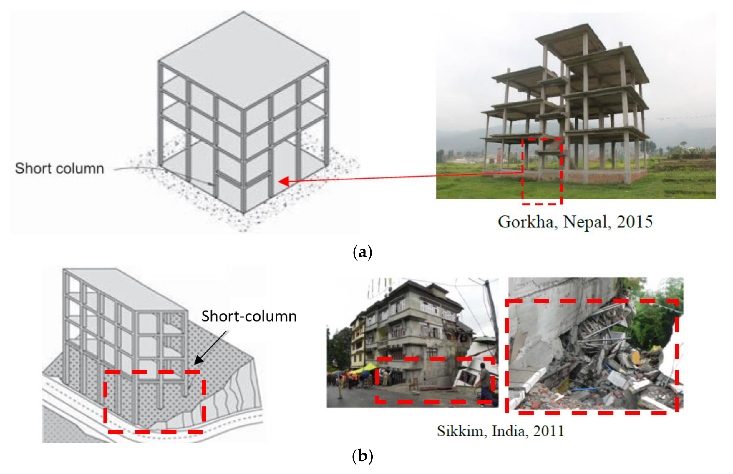
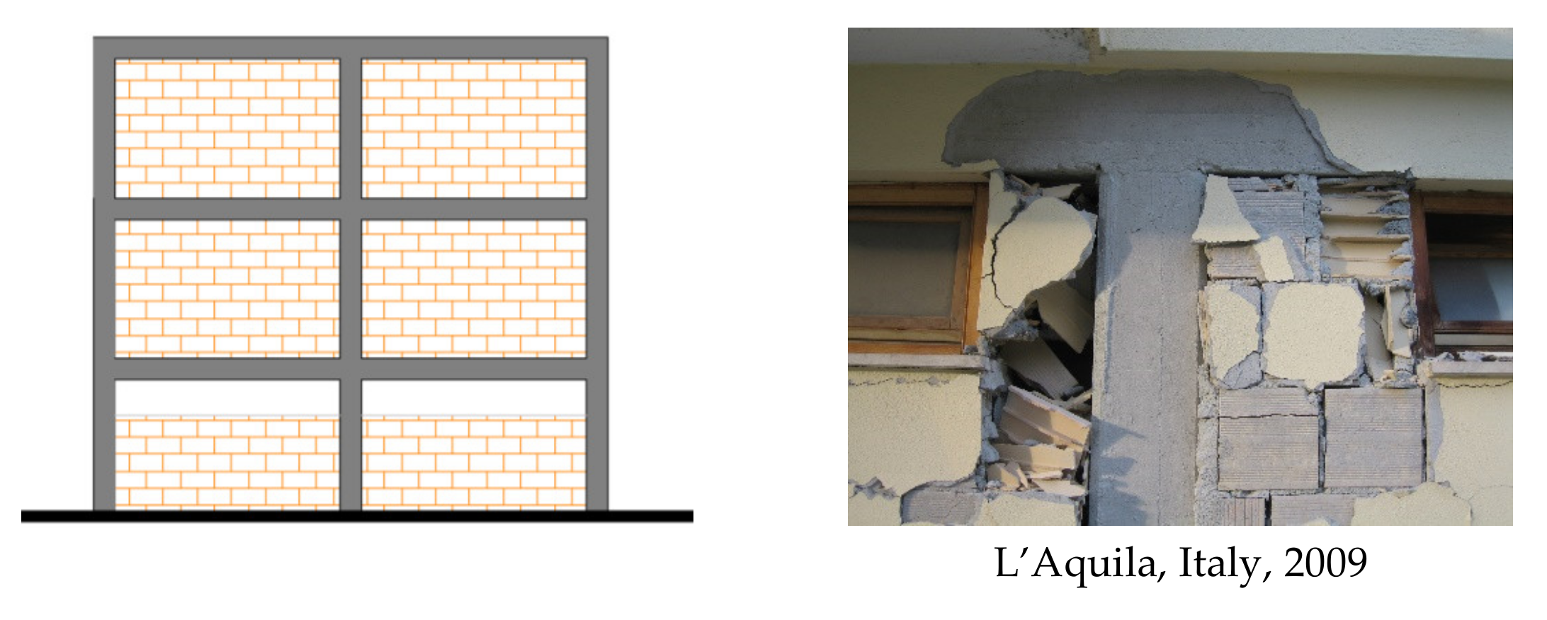
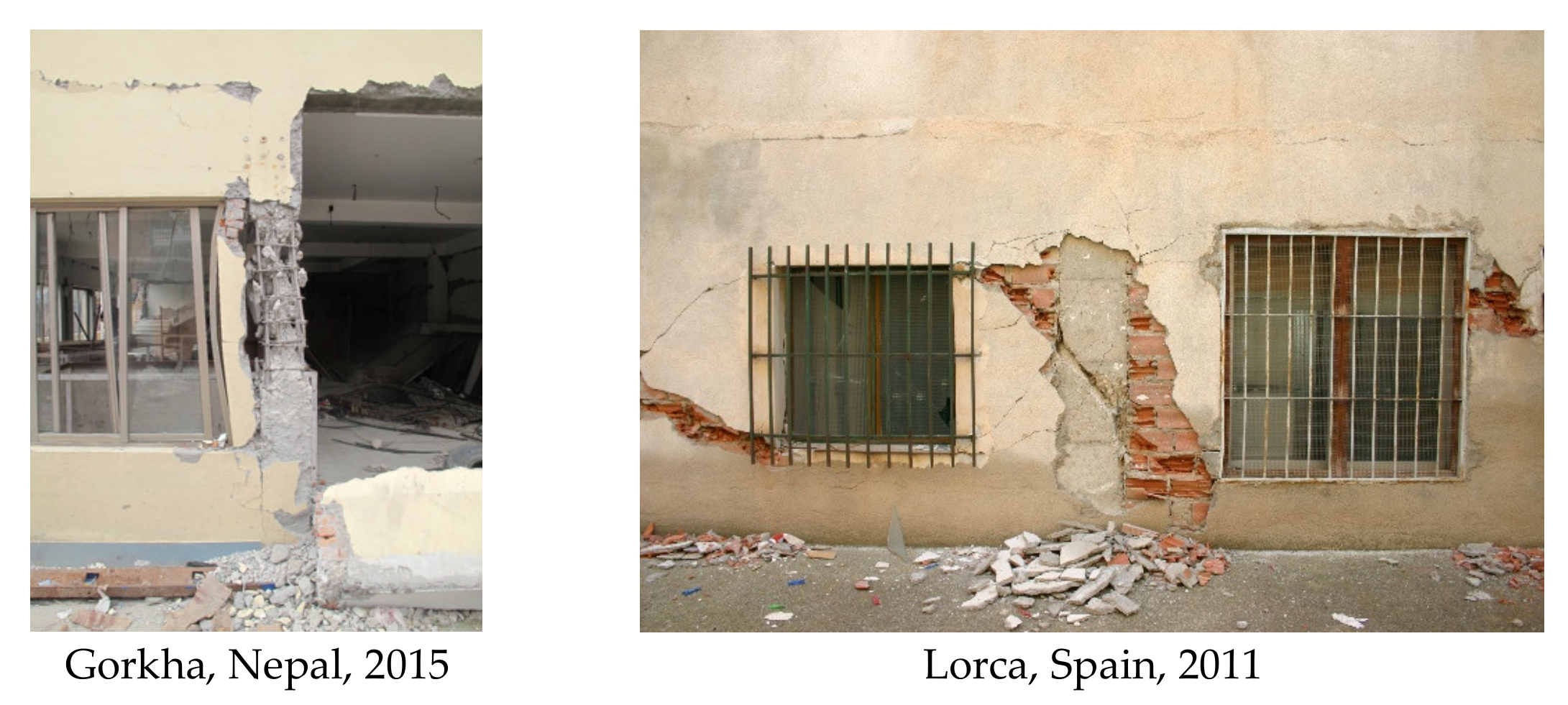
2.1.6. Damage Type 6: Damage Associated with Short-Column Mechanism

One of the most common failure mechanism observed in RC structures is the short-column mechanism. There are three types of situation where the short-column mechanism can be triggered out:
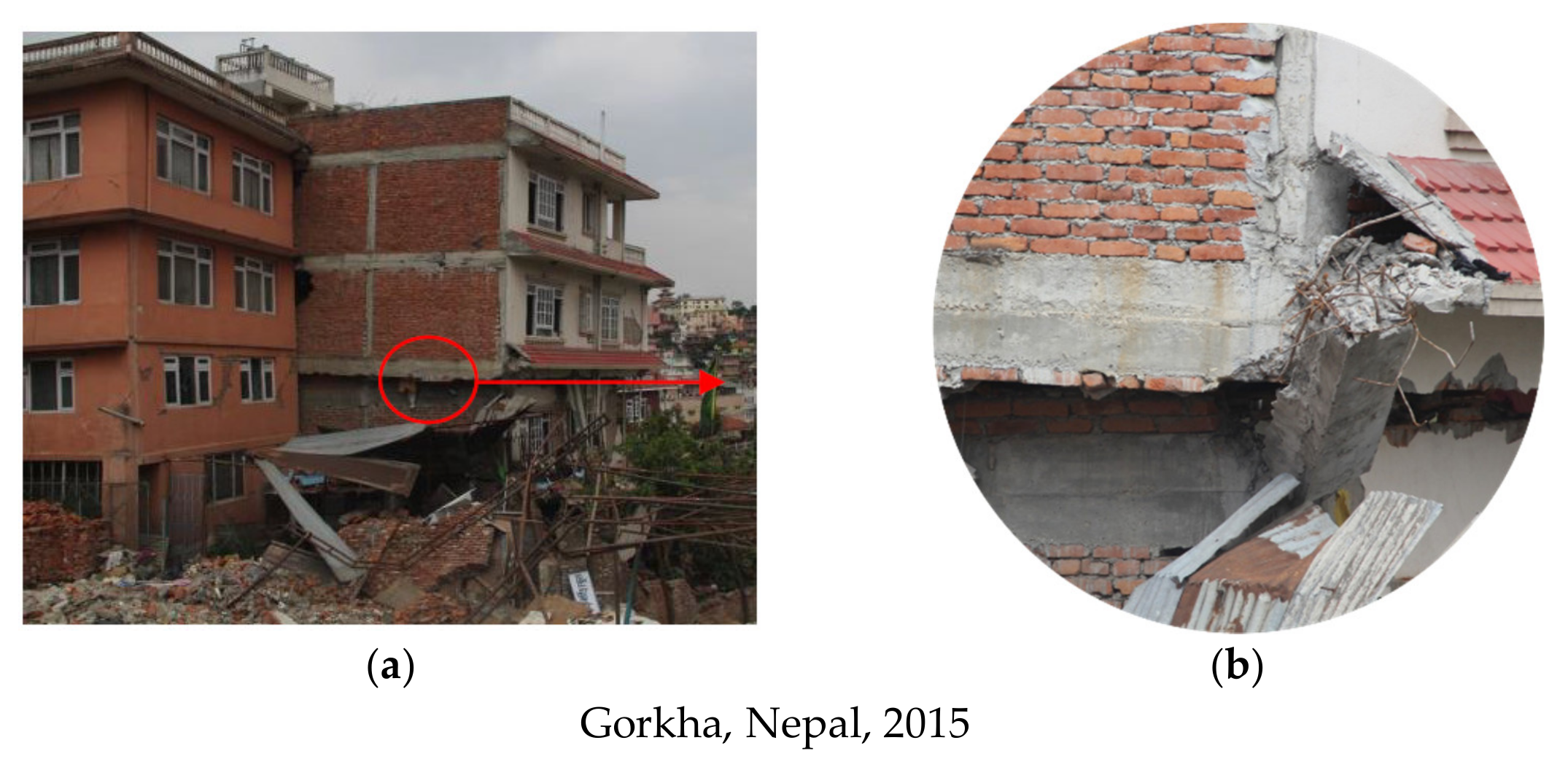
Situation 1: Existence of columns shorter than others in a moment-resistant frame system. It is well-known that the stiffness of shorter columns is inversely proportional to their length. Examples of this situation are beams for stairs support linked to the surrounding columns and, subsequently, reduce the columns’ length. This situation is quite commonly observed in Nepal, as shown in Figure 9a. Some examples of short-column mechanism due to this structural configuration have resulted in the collapse of the columns;
Situation 2: Building structures located in inclined plans, which lead to columns at the same building level with different length, as shown in Figure 9b. It is possible to observe an RC structure severely damaged after the India Earthquake in 2011 [28];
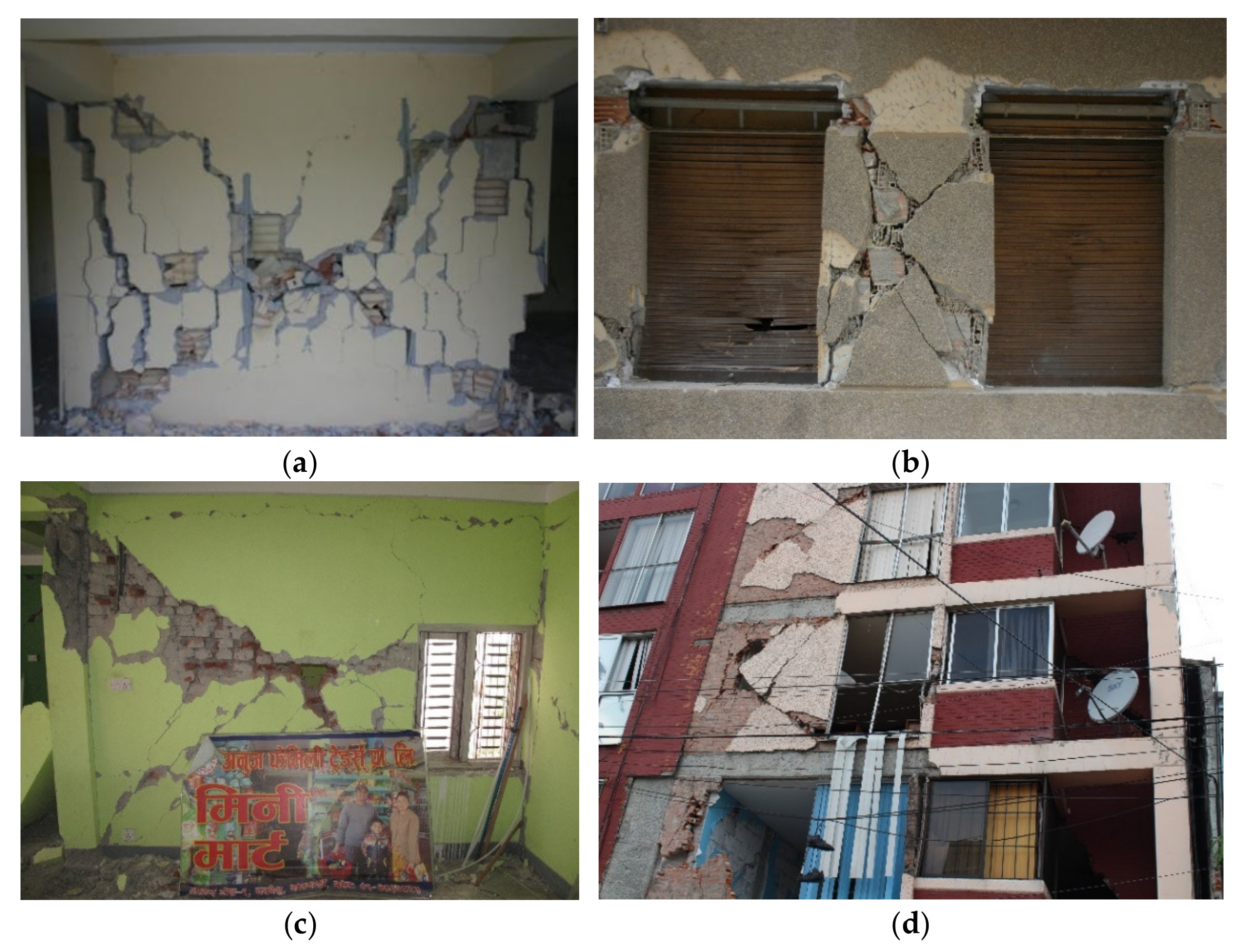
Situation 3: The third situation in which the short-column mechanism can occur is when the column is adjacent to infill panels that do not fill the total column height. As mentioned before, the infill panels are not considered in the structural and seismic design. However, they have an essential contribution in terms of strength and stiffness, leading to different behaviour than what was initially predicted. In addition, many infill panels do not fill the total floor height in the construction, such as openings such as doors or windows, leaving a short part of the column exposed to higher shear demands. This situation is not considered in the structural design and is likely to potentiate the shear failure mechanism of those columns (Figure 10). The column failure can redistribute additional loadings to the remaining structural elements, thus increment their vulnerability and, consequently, the building structure vulnerability.
The short-column mechanism can be minimised or prevented through a previous study that combines architectural and structural projects. In other words, the columns’ and shear walls’ design and/or assessment must be carried out after defining the disposition of the infill panels and the corresponding openings. With this easy strategy, it will be possible to improve the potentially vulnerable zones of the columns subjected to higher shear loadings.

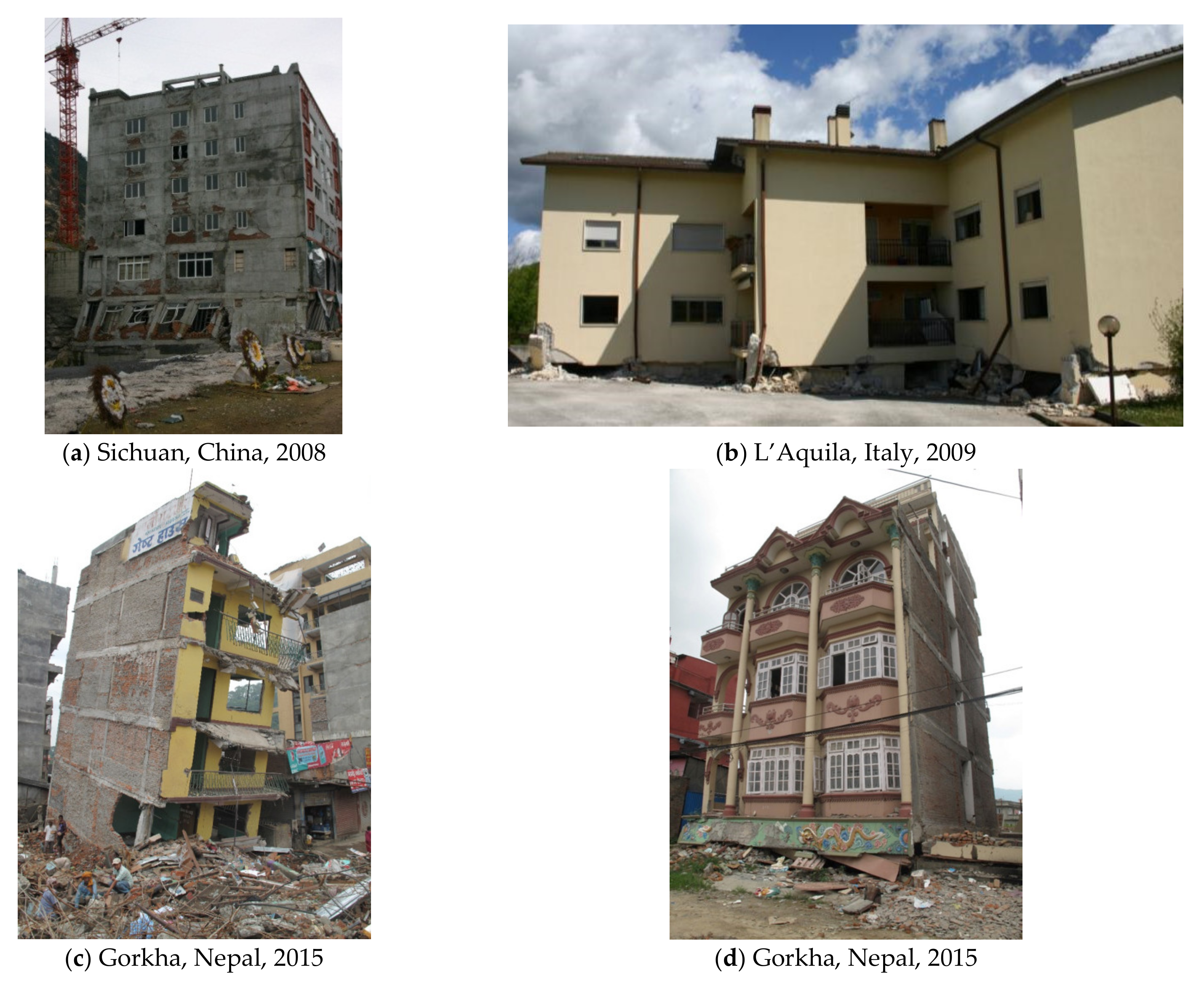
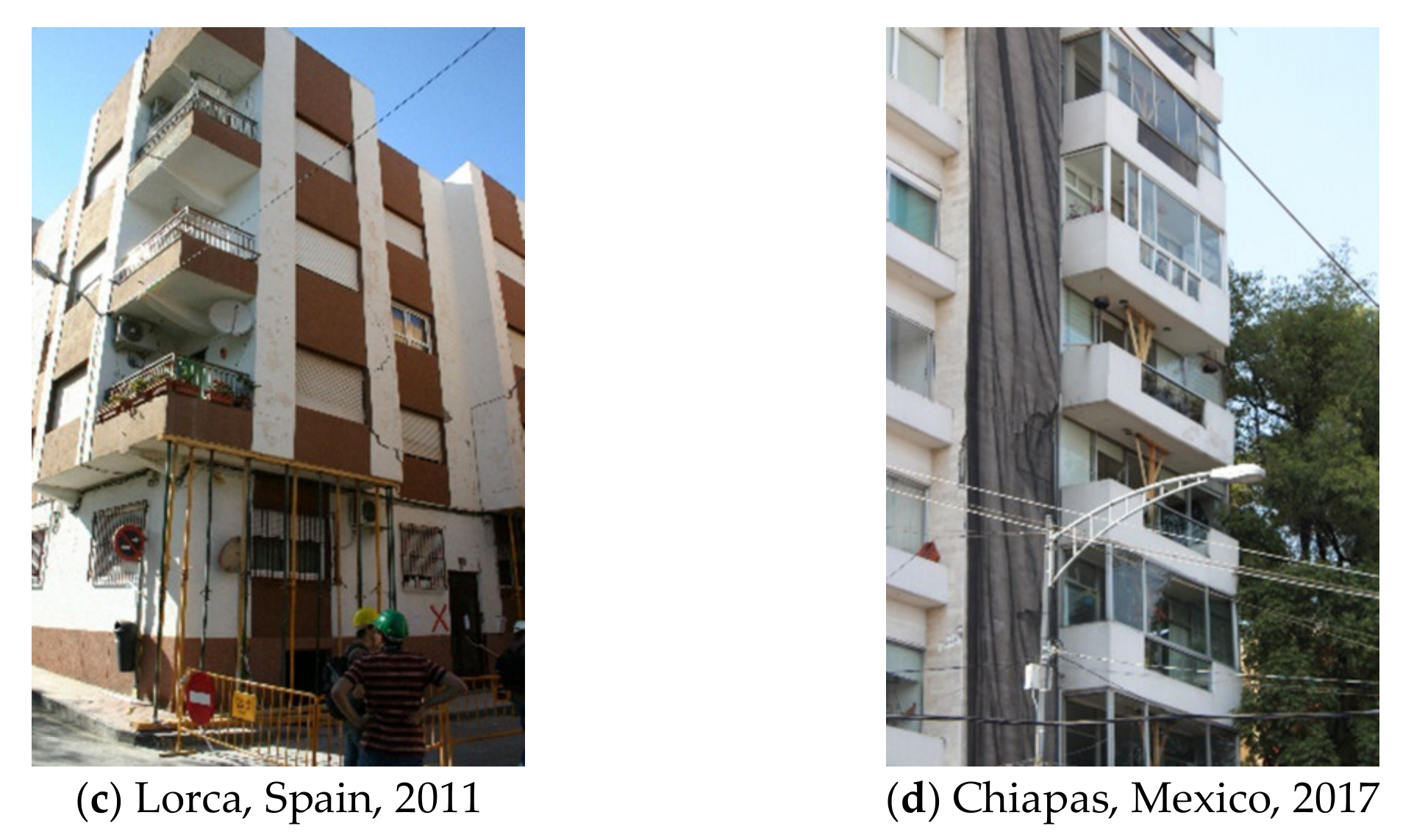
2.1.7. Damage Type 7: Damage Associated with Structural Irregularities (in Plan and/or in Elevation: Torsion, ‘Weak-Storey’ and ‘Soft-Storey’)

A proper structural conception is essential to ensuring a good performance against any type of loading demand. Simple-, regular- and redundance-resistant systems for horizontal loading demands tend to result in better behaviour. By contrast, complex structural systems usually result in structures in which the dimensions and detailing of structural elements show some deficiencies. Abrupt variations of stiffness, strength, mass and/or other elements’ properties in one building, either in a plan or in elevation, can result in horizontal loading distributions and deformations much different from those usually occurring in regular structures.
A very common structural irregularity is observed at the buildings bottom storey. The architects usually remove the infill panels for using these spaces for retail stores, garages or only due to architectural reasons. This type of construction practice often results in the deformation of these empty storeys under seismic action, triggering the soft-storey mechanism (Figure 11). Typically, this failure mechanism is characterised by the shear or bending failure of the columns and consequent collapse of the storey. In many situations, the destruction of the soft-storeys was observed while the remaining ones were intact (or just with very slight damage).
Figure 12 shows two residential buildings that partially collapsed due to the soft-storey mechanism. Figure 12a shows the front view of a six-storey building with a commercial storey on the ground-floor. Figure 12b shows a residential building, 4-storeys’ high, with a garage on the ground floor that collapsed during the L’Aquila earthquake. This type of damage can be prevented by ensuring a uniform in-elevation distribution of the infill panels and structural elements (columns and shear walls).
In Portugal, particularly in the Lisboa region, several infilled RC structures built in the 1950s decade were designed with this structural configuration, inspired by Le Corbusier, where the primary system is supported by pillotis to allow the circulation of the people, garage and commerce, as shown in Figure 13. Residential buildings with vertical irregularities, located in Lisboa and Silves, are shown in Figure 13a–c. Additionally, Figure 13d presents a school with the same structural irregularity.
Other examples of stiffness irregularities were found at the upper-storeys, which resulted in their collapse without leading to the total failure of the building structure. For example, Figure 14a,b shows a 5-storey building severely damaged due to aftershock following the Gorkha (Nepal) earthquake in 2015. The collapsed storey corresponded in the past to a restaurant with a lower number of infill panels when compared with the remaining storeys. This irregularity resulted in the deformation concentration and high shear demands and thus the collapse of this level. In 2017, the same phenomenon was observed in Mexico, where the partial collapse of the fourth storey of an 8-storey building occurred (Figure 14c).
Another issue that can trigger the soft-storey mechanism is the abrupt in-elevation reduction of the cross-section of the column. Another common irregularity is associated with modifying the position between consecutive storeys, of the vertical structural elements, or/and of the non-structural elements.

2.1.8. Damage Type 8: Damage Associated with Pounding

Another typical damage observed in the urban area is the absence of proper and designed gaps between building structures. This lack of space between adjacent buildings increases the probability to develop interactions between them during an earthquake event, commonly designated as pounding effect.
Concerning the new constructions, a simple strategy that can prevent the pounding effect consists of subdividing the entire building with seismic joints (dynamically independent units) seismically designed to prevent the pounding between the units, as shown in Figure 15.
The mitigation of this phenomena becomes more complicated regarding the existing constructions, which is the most common situation since it depends on many variables. A possible strategy is strengthening both building structures to ensure superior individual seismic performance, minimising the buildings displacements and the pounding consequences.
Several damages were reported due to the pounding effect during earthquakes (i.e., Lorca in 2011): adjacent buildings with different height and/or structural configurations and materials (Figure 16a), the urban centre, facing the different dynamic responses, results in shocks between the buildings (pounding) and thus accumulate stresses in specific common points between adjacent buildings (Figure 16b–d).

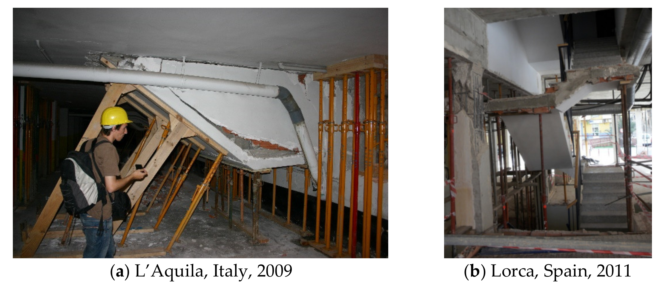
2.1.9. Damage Type 9: Damage in Secondary Elements (Cantilevers, Stairs, etc.)

After the last major earthquakes, the damage observed in the infilled RC structures was also reported and linked to secondary elements such as stairs and/or cantilevers. In the case of stairs, some partial collapses were observed and were related to the absence of proper design and/or poor detailing combined with constructive errors and no connection of the stairs to the primary structural system. Examples of this type of damage are shown in Figure 17a,b. Concerning the balconies and cantilevers, some collapses and excessive deformation were caused by the vertical accelerations (Figure 17c,d).
Finally, it is vital to highlight the poor performance and collapse of masonry parapets, as shown in Figure 18. Romão et al. [15] reported that the failure of these elements was the primary cause of fatalities in the Lorca (Spain) earthquake, since the parapets fell from the top of the buildings during the quake, hitting people that were in the streets. It was pretty common to observe parapets not linked to the structure, which resulted in their high out-of-plane (OOP) collapse vulnerability. This problem could be mitigated by designing an effective parapet connection to the structure and preventing its collapse.

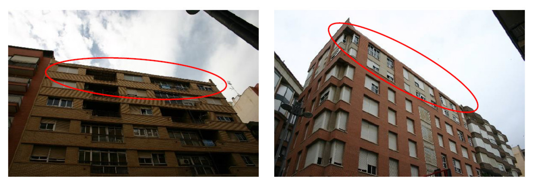
2.1.10. Damage Type 10: Damage in Non-Structural Elements

Infills represent the external skin of the RC structures; they are generally used as interior partitions and to separate the inner spaces from the outside. Constructive techniques strongly depend on each country’s construction practice (double or single leaf infill, connection system between infill panel and the surrounding frame, and workmanship). This aspect can introduce a significant heterogeneity in the influence of infills on the RC buildings performance due to earthquakes. Infill panels generally increase the lateral stiffness and strength, at least at low displacement demand, and profitable growth of the dissipated energy during ground motion. On the contrary, the infill panels can induce significant detrimental effects, positively affecting the damage-limitation performance level and potentially dangerous for life-safety, as discussed in the following remarks.
The infill masonry walls tend to detach from the envelope frame for low seismic demands, as proved by the cracking around the panel contours. Besides using different types of masonry units (solid or hollow bricks), the in-plane detachment of the panels tends to occur due to their incapacity to follow the frame deformation during the seismic event, as shown in Figure 19. Multiple examples are herein presented following the earthquakes in Spain in 2011 (Figure 19a), Nepal in 2015 (Figure 19b), Mexico in 2017 (Figure 19c) and Ecuador ((Figure 19d).
Moreover, it is well-known, infill panels generally exhibit a diagonal damage pattern due to the horizontal action parallel to their plane, as shown in Figure 20. Such damage can be more or less diffused across the building and generally concentrated at the lowest floors, where the relative displacement demand is typically higher. Such damage is clear evidence of the interaction of infills with the RC structure seismic response. Therefore, their typical definition of ‘non-structural’ components can be considered as not appropriate. Furthermore, the infill panels damage is often particularly severe under moderate seismic shaking, proved by the economic seismic losses reported in recent earthquakes [29], and casualties, thus reducing the seismic resilience of the communities in seismic-prone areas [5].
Some other damage mechanisms commonly found in the infill walls due to the in-plane seismic demands were the sliding cracking and the corner crushing. The sliding failure is typically characterised by a horizontal crack at the panel middle height. It is justified by its high in-plane stiffness, which reduces the capacity to deform and then develops the sliding along the horizontal bed joints. This type of damage was often observed in the Gorkha earthquake in Nepal due to the solid clay bricks commonly used there to build the infill walls. These type of bricks are combined with cementitious mortars resulting in panels with high in-plane stiffness. Some examples of this type of damage are shown in Figure 21a,b. In addition, the accumulation of the stresses transferred by the in-plane loading demand can result in the bricks crushing. This type of damage, shown in Figure 21c,d, is often combined with diagonal cracking or detachment of the panel.
One of the biggest problems related to the infill walls was the high number of out-of-plane (OOP) collapses (or overturning) observed. The walls collapse can occur since mechanical connections are not used between the ‘non-structural’ panel and the RC frame. The problem also becomes more severe in these cases due to the usual high slenderness of infills in existing buildings, generally made with two leaves (not adequately connected). As a result, the overturning of the infills is usually observed in post-earthquake field missions, as shown in Figure 22, enhanced by the combination between the damage due to in-plane actions and the transverse acceleration demand during a seismic event.
Some authors pointed out that the inadequate support condition of the panel reduced the panel resistance capacity to OOP loadings. This solution is commonly adopted due to thermal concerns. However, the enormous in-plane demands subjected to the panels leads to higher damage levels, reducing the OOP-resistant capacity. Most often, the OOP collapse was observed in the intermediary storeys of the structures. Figure 22 shows examples of OOP collapses in RC structures composed of 3–5 storeys. As shown in the Figure 22, the level of destruction caused by the panel collapse is high, representing a significant risk for human life safety and economic losses.
The OOP collapse was also observed in medium-high RC structures, Figure 23, in the intermediary levels comprised of the panels’ total failure and consequent collapse. In addition, some other panels with openings, which suffered damage due to the in-plane seismic demands, partially collapsed.
Different investigations were carried out concerning the OOP behaviour of masonry infill walls, from which it was concluded that the OOP strength reduces with the increasing of the panel slenderness [30,31]. Ricci et al. [31] performed a series of OOP tests assessing the effect of the walls slenderness in their OOP behaviour. Before the OOP tests, the walls were subjected to different in-plane damage levels (Low—0.30%; Medium—0.60% and High—1%). Hollow clay horizontal units were used to construct the scaled walls with slenderness equal to 22.9 and 15.2. It was observed during the tests a more significant decrease of the OOP maximum strength and initial stiffness for the thinner panels.
De Risi et al. [32] carried out a testing campaign to study the effect of the panel aspect ratio (1.28 and 1) in their OOP response. The authors found that square and rectangular infills have very different damage states. For examples, the rectangular walls showed more damage than the square ones. Furthermore, for panels previously subjected to low in-plane drift (0.30%), the square panel exhibited a strength reduction of 24%, while the rectangular panel reduced by about 52%.
The in-plane and OOP behaviour interaction seems to be one of the most critical issues. Different authors report that the previous damage reduces the panel OOP strength [31]. The damages caused by prior IP demands affect OOP performance’s infill walls, causing the reduction of the maximum strength capacity and modifying the expected failure mechanism. Some experimental works [4,5,6,7,8,9] were developed to study this behaviour interaction by performing OOP tests on panels first subjected to different in-plane damage levels.
Angel et al. [33] carried out a testing campaign comprising three infill panels made with solid clay bricks (SCB) units (slenderness = 33.9). The reference specimen was subjected only to a uniform monotonic OOP loading and reached a maximum peak load of 8.18 kN/m2. The remaining models were tested first to in-plane loading demands with different target drift levels, namely 0.22% and 0.34%. After that, the panels were subjected to monotonic OOP loading until the panel collapses. The results showed a reduction in the maximum strength of about 27% and 51%, respectively. Unfortunately, the authors did not provide any details regarding the failure mechanism.
In 2001, Calvi and Bolognini [34] tested two full-scale, single panels, made with hollow clay horizontal brick units, with slenderness equal to 20.4, subjected first to an IP cyclic loading and later to an OOP monotonic loading. Two other specimens were first subjected to a maximum IP drift equal to 0.4% and 1.2%, respectively. Afterwards, both were subjected to a monotonic OOP load applied on four not aligned points. The results showed a reduction of the OOP maximum strength of about 75% and 82%, respectively. Unfortunately, no reports were provided concerning the cracking pattern or failure mechanism of any of them. Pereira et al. [35] carried out seven tests, 1:1.5 scaled subjected to combined tests. Nevertheless, no specimen was subjected only to pure OOP loading, and thus the effect of the previous in-plane damage in the panel response was not assessed.

3. Economic Losses Due to Earthquakes Related to the Infill Panels

The seismic action is paramount among natural hazards affecting civil infrastructures and human activity all over the world. Major earthquakes have been responsible for the death toll of thousands of people per year in the past decades [4,14,28], as well as economic losses that can reach a significant fraction of a country’s welfare. The importance of the non-structural components in building performance under seismic action is well recognised in the scientific community, as shown in the previous sections. Furthermore, the damage observed in residential buildings in past earthquakes demonstrated that the damage to non-structural components represents a substantial contribution to the resulting economic losses.
Loss estimation methodologies are crucial tools for governments and insurance companies to predict the consequences of earthquakes. Several methods are available in the literature to correlate damage and losses. They assume different procedures to compute the seismic hazard, the building response due to seismic actions and the estimation of economic losses.
De Martino et al. [36] carried out a preliminary work concerning the correlation of the damage detected by in situ inspections and the repair costs determined according to repair interventions designed and computed by practitioners engaged by owners in a post-earthquake reconstruction process. For that, the authors supported the study in data collected on damaged residential RC buildings after the L’Aquila earthquake (Italy). After the earthquake, teams of seismic engineering teams visited 74,254 buildings with severe, light or no damage. In addition, the teams built a database containing first-level data gathered in a rapid visual inspection, such as the geometrical building characteristics, construction age and renovation, type and damage on structural components (vertical and horizontal structures, roofs, stairs and infill partitions) and non-structural elements. The repair costs of damaged buildings were fully covered by public funds, while different upper bounds were fixed for the costs of strengthening interventions based on building usability rating. For each damaged building, several funding applications for relevant repair (for condominium units, i.e., dwellings) and repair and strengthening (for common areas and structural parts) projects were submitted by owners’ engaged practitioners to a proper commission. In that study, the empirical damage on residential buildings was derived through data collected using the AeDES (‘Agibilità e Danno nell’Emergenza Sismica, Usability and Damage in Post-Earthquake Emergency’) form. The damage level is then divided according to six intensities, namely no damage (null), slight damage (D1), medium-severe damage (D2-D3) and very heavy damage (D4-D5). The AeDES form also reports the damage extension on each structural component, namely if the damage extent is lower than 1/3, between 1/3 and 2/3, and greater than 2/3 of the storey components.
The authors found that the most frequent damage in infill partitions was medium-severe (D2-D3), and a large number of observed damages was related to the infills partitions in three types of damage extensions (<1/3 extent, 1/3–2/3 extent and >2/3 extent of the storey components). Very heavy damages were found in masonry infill walls from 418 buildings (28% of the total buildings). The authors also studied the costs related to repair interventions, which consisted of: (a) Repairing of damaged non-structural parts and relevant finishing works; (b) local repair of damaged structural components; (c) demolition and reconstruction of fully damaged or unsafe non-structural or secondary structural elements (i.e., interior or exterior infills, outdoor curtain wall, heavy plasters, fireplaces and chimney-pots, porches, eaves, repair of damaged facilities, etc.). The repair costs included building safety measures; demolition and removal, including transportation costs and landfill disposal; repair interventions; repair and finishing work relevant to strengthening intervention. The authors found that the damage index related to the infill panels reached values more excellent than those associated with the other components and observed that the number of storeys affected more the infill panels’ damage than the seismic design of the structure. The authors concluded that the total repair cost for RC buildings is mainly affected by the damage to infill partitions and vertical structures. The authors pointed out that the demolition and reconstruction resulted economically more viable in 59 RC buildings out of 1500 of the dataset. However, the authors only provided the average cost estimation for demolition and reconstruction of private residential buildings damaged by the L’Aquila earthquake, which resulted in 1192 €/m2. The authors carried out the calculation of the rehabilitation costs of 59 buildings, in which the authors found a building repair cost ratio (the relationship between the actual repair costs and the building value) equal to 512 €/m2, however it is not mentioned that the costs explicitly related due to the infill panels.
Later, Sousa and Monteiro [37] carried out a study concerning the impact of the non-structural partition walls on building losses due to earthquake action, focusing on the potential contribution of non-structural retrofit solutions to reduce seismic losses. The authors developed a numerical study based on the analysis of six building configurations (3, 6 and 9 storeys with different infill panels) without seismic provisions. The seismic vulnerability safety assessment was then performed and correlated with the cost of implementing the selected retrofit solutions and the benefit achieved through the corresponding reduction of earthquake losses throughout the building’s life cycle. From the study, the authors concluded that: (i) The decline in the annual economic losses achieved through non-structural retrofit, for structures with and without soft-storey, are similar, with a range of 10% to 40% of the annual economic losses of non-retrofitted structures; (ii) high-rise buildings without soft-storey are less affected by the implemented retrofits, in terms of the achieved reduction of annual economic losses.
Recently, De Risi et al. [29] carried out research work to investigate the seismic losses due to masonry infills damage in RC structures after 2009 L’Aquila (Italy) earthquake, focusing on the dataset of ‘lightly’ damaged buildings, where only damage to masonry infills occurred. Based on the available data related to these buildings (a portion of the database collected by Dolce et al. [38]), the observed damage scenario after L’Aquila earthquake was first obtained. The repair costs for infills were estimated, given this damage scenario. The resulting estimated repair costs were then compared with the actual repair costs presented in the available literature. The authors used the damage scale based on AeDES form [39], which provides more details concerning the definition of each damage state, namely:
Grade D1 (‘Slight’) is a damage level for which small detachments (<1 mm) of the infill panels from the surrounding beams/columns can occur, with possible cracks (<1 mm width) due to the participation of the infill to the total lateral strength of the building. This damage level for infills can contribute to defining a ‘low’ damage level in the building unless there is a certain degree of risk of out-of-plane collapse due to the possible absence of connection between the panel and other structural components;
Medium-severe damage state (D2-D3) corresponds to cracks (between 1 and 5 mm) due to detachment from the surrounding elements, diagonal cracks up to ‘some’ millimetres, and a quite evident corner crushing with some localised bricks’ expulsions. If a large number of infill panels are affected by this damage level, the total structural risk can be ‘high’;
Damage states ‘heavy damage’ (D4-D5) are related to cracks’ width and extension on the infills significantly more severely than for the previous damage level.
In the study carried out by De Risi et al. [29], the authors only considered the buildings for which the AeDES form [39], reported damage to exterior infills and interior partitions and ‘Null’ damage to all the other structural components.
The authors also presented the correspondence between the European Macroseismic Scale commonly designated EMS-98 [40] and the AeDES form [39], which was used for the remaining part of the repair costs quantification; here is presented the relationship between the damage.
From those analyses, the authors concluded that 2406 buildings presented no damage in infills and partitions (and no damage in vertical structures, roofs, stairs, etc.,). A total of 1943 buildings were in damage level DS1, 555 were in DS2 and a smaller portion (191 buildings) presented a damage level of DS3. Mean values of those costs ranged from about 37 €/m2 to about 230 €/m2, passing from DS1 to DS3. They were not affected by the age of the buildings; only a slight decrease is observed for an increasing number of storeys, and a more significant reduction is obtained for a larger average plan area. Due to masonry infills, the predicted repair costs resulted, on average, equal to 50% of the total actual repair cost (the latter evaluated according to Dolce and Manfredi [41]), thus highlighting the paramount importance of considering the infill contribution in seismic loss assessment for RC buildings.

4. Case Study

This section presents a case study of an eight-storey infilled RC building representative of southern European countries. Based on the discussion presented in Section 2, it was concluded that soft-storey configuration (absence of infill walls at the ground floor) is considered one of the most dangerous irregularities that can cause the collapse of the building. Thus, this section aims to present some examples of different strengthening strategies that can eliminate the soft-storey mechanism and reduce the vulnerability of such structures.

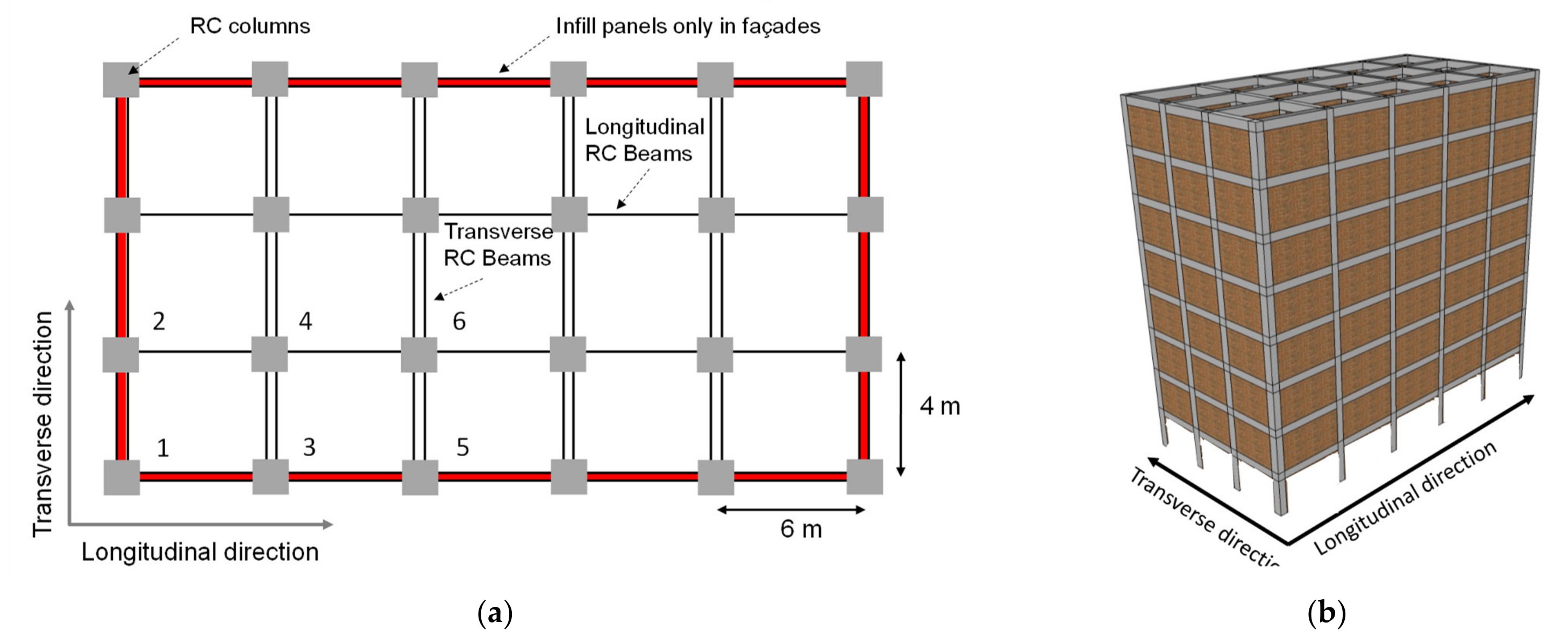
4.1. Description of the Building

The building has the plan dimensions of 20 × 15 m2, consisting of 4 × 5 m2 modules, with a storey height of 3 m. The building was designed by the Portuguese Laboratory of Earthquake and Civil Engineering (LNEC), according to the design code enforced in the 1980s in Portugal [42]. The layout considered for the infill walls is illustrated in Figure 24. The cross-sections of the columns are: 0.30 × 0.60 m2 (Storey 1 and 2); 0.30 × 0.50 m2 (Storey 3 and 4); 0.40 × 0.30 m2 (Storey 5 and 6) and 0.30 × 0.30 m2 (Storey 7 and 8). The columns’ cross-sections are presented in Figure 25. The beams’ cross-section is 30 × 60 cm with different reinforcement detailing according to the structure’s storey and layout. The beams cross-sections are presented in Figure 26. More details concerning the reinforcement detailing of all the structural elements can be found in [42]. Concerning the building’s design, a global vertical load of 6.15 kN/m2 plus a variable load of 2.5 kN/m2 was considered. The selected concrete grade is C25/30, and the steel reinforcement grade is A400 [42]. A 3D model was generated in the software SeismoStruct [12], considering the disposition of the masonry infill walls along the structure’s external perimeter and the building height, except at the ground floor. The layout considered for the infill walls distribution is illustrated in Figure 24.
Single leaf infill walls were selected for this study, representing the traditional unreinforced masonry panels constructed in Portugal, with complete contact with the surrounding RC frame and hollow clay weak bricks 150-mm thick. The relevant infill properties were selected based on the mechanical characterisation tests performed by Furtado, et al. [43], and are described in Table 1.
Here fc,h and fc,v are respectively the values of infill panels compression strength parallel and normal to bed joints, while fw,u stands for the sliding shear strength of the mortar joints and Ss for the shear strength obtained from diagonal tensile strength test; Ew,h and Ew,v are the secant elastic modulus parallel and normal to bed joints, G is the shear modulus and W is the self-weight of the infill walls.

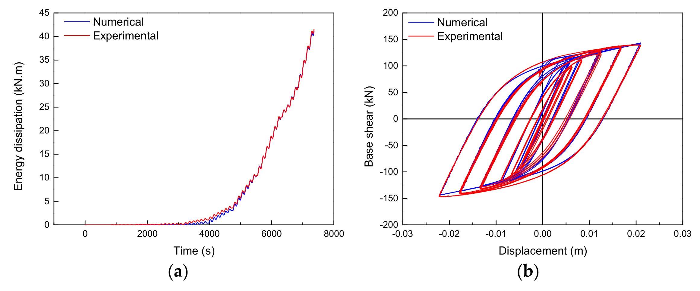
4.2. Numerical Modelling Strategy

The material model proposed by Mander [44] was adopted to simulate the confined and unconfined concrete behaviour. The Menegotto-Pinto [45] material model was selected for the steel reinforcement. The masonry infill walls were simulated using the macro-model proposed by Crisafulli [46] and all the parameters required to define the hysteretic behaviour were determined according to Smyrou proposal [47]. For the numerical analyses, constant vertical loads distributed on beams were considered to simulate the self-weight’s dead load, including RC elements and infill walls, finishing and the corresponding quasi-permanent value of the live loads. The mass of the structure was assumed to be concentrated at storey levels. Each storey has a mass, including the self-weight of the structure, infill walls and finishing, and the live loads’ quasi-permanent value. For the dynamic analysis, the storey mass is assumed to be uniformly distributed across the floors.

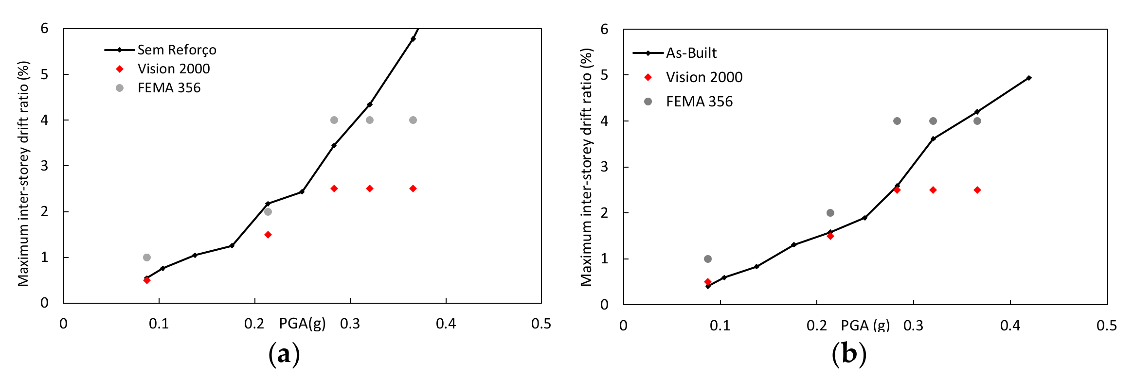
4.3. Seismic Vulnerability Assessment

The building understudy was subjected to several non-linear dynamic analyses, particularly to one artificial earthquake generated for a medium/high-risk scenario in southern Europe [48] for different return periods (Table 2). Hazard-consistent time series of acceleration (with 15 s of duration) were artificially generated, yielding a set of ten uniform hazard response spectra for increasing return periods (RP). Figure 27 shows the ground motion acceleration of seismic action for the return period of 2000 years.
The obtained results verify the safety according to the hazard levels proposed by the international recommendations VISION-2000 [49] and FEMA-356 [50] to evaluate the building safety. In addition, other global drift limits have been used, namely the Gobarah proposal [51] recommended for non-ductile structures, which is the case of rehabilitation/strengthening of existing buildings. All the proposed limits drifts are presented in Table 3.
The maximum inter-storey drift ratio obtained in the non-linear dynamic analysis results is plotted in Figure 28. It can be noticed that the maximum inter-storey drift reached by the building exceeds the drift limits recommended by VISION 2000 [49] and by FEMA-356 [50]. The maximum inter-storey drifts were always reached at the first level of the structure due to the absence of the masonry infill walls. Concerning the longitudinal direction (Figure 28a), the drifts are always more significant than the limits imposed by VISION 2000 [49], namely about +10% at 0.08 g, +45% at 0.21 g, +37% at 0.28 g, +74% at 0.32 g and +131% at 0.37 g. Moreover, the structure exceeds the FEMA-356 [50] drift limits for a PGA equal to 0.21 g (+9%), 0.32 g (+8%) and 0.36 g (+44%).
Concerning the transverse direction, the drift limits reached during the analyses were slightly lower than those achieved in the transverse direction (22–39%), except for the PGA of 0.18 g where they get a similar inter-storey drift ratio of 1.26%. The FEMA-356 [50] drift limits were not respected since, for the PGA of 0.37 g, the structure exceeded the limit by about 5%.
On the other hand, the VISION 2000 [49] drift limits were always exceeded, except for the PGA of 0.08 g. Based on these results, it can be concluded that this structure seems to be vulnerable under seismic action. In particular, this vulnerability is caused by the vertical irregularity caused by the masonry infill walls distribution, a problem identified in all the post-earthquake damage survey reconnaissance missions presented in Section 2.

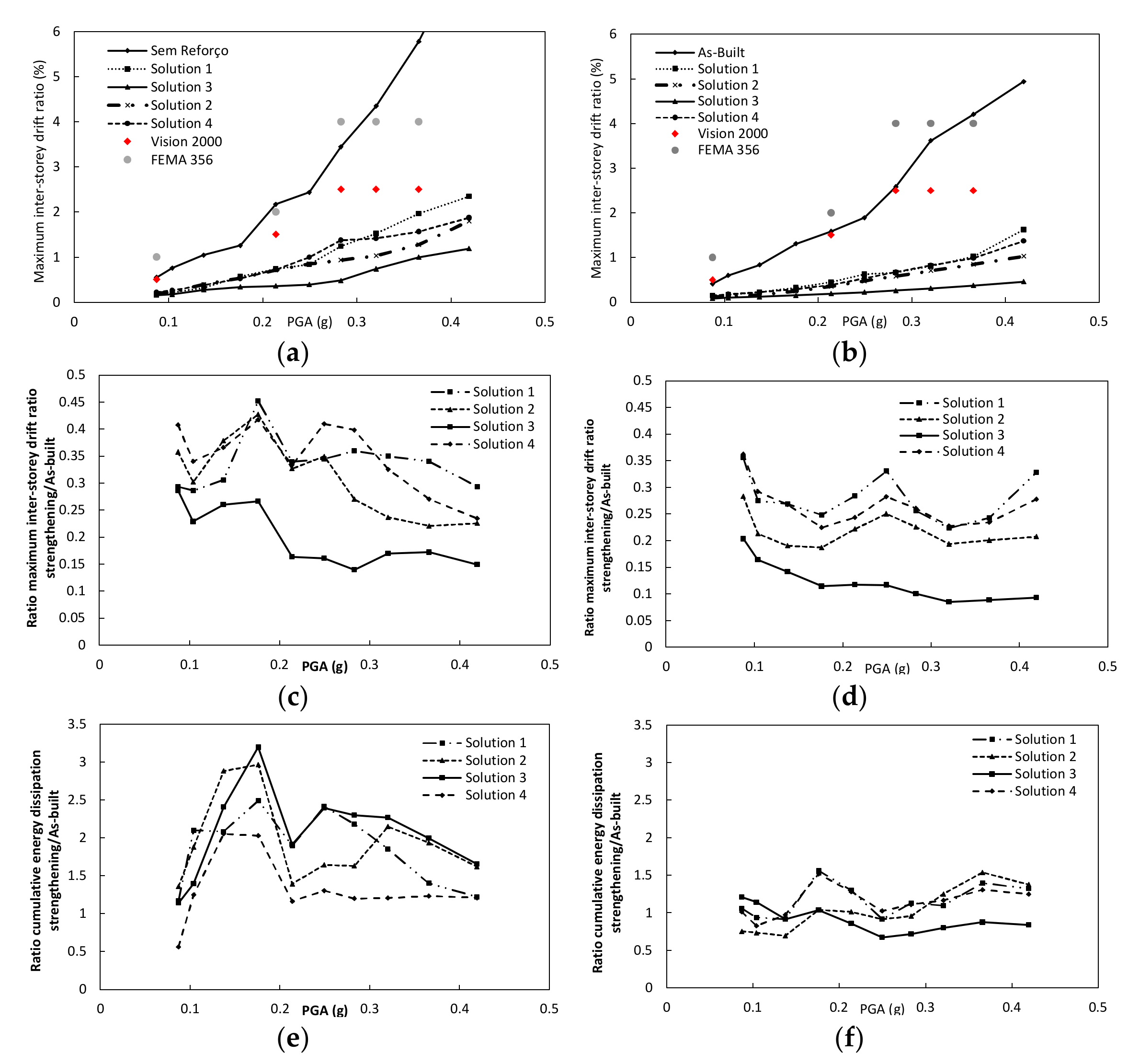
4.4. Assessment of Possible Strengthening Interventions

The selection of the strengthening technique and the level of intervention is a rather complex procedure because many factors of different nature come into play. The fundamental parameters governing the structural response of the building when submitted to seismic actions are stiffness strength and ductility [52]. In addition, some factors affect this process, such as socio-economic issues, cost-benefit aspect and importance of the building, work duration, conditioning of the utilisation of the structure, functionality and compatibility with the intervention and the original architecture of the building [53]. In any case, selecting the strengthening strategy to adopt and its implementation should be developed based on the results of a preliminary structural assessment. The strengthening plan can be classified according to these two major groups [52], namely:
Global structural system intervention techniques: Most situations are less costly than the intervention in all structural members. Especially if these types of intervention require temporary interdiction of the building, demolition and/or reconstruction of non-structural elements such as masonry infill walls or false ceilings. The most well-known, economics and efficient global strengthening techniques are: RC structural shear walls; steel braces with and without energy dissipation (shear link); seismic isolation; mass reduction or another technique including tuned mass; and liquid dampers or a hybrid combination of active and passive energy-dissipation device.
Member intervention technique: this type of strategy aims to increase the deformation capacity of deficient components to not reach their limit state as the building response at the required level. Some structural elements do not have the adequate strength, stiffness or deformation capacity to satisfy the strengthening objectives. Members without good strength, stiffness and/or ductility can be strengthened using various types of techniques. The most familiar member interventions are: RC jacketing, steel jacketing, CFRP jacketing, injection of cracks, epoxy resin injections, shotcrete and others. This strategy tends to be the most economical approach to strengthening when only a few buildings’ components are inadequate.
Four types of strengthening solutions were tested to improve the seismic behaviour of the building under study: RC jacketing of the ground floor columns (solution 1), the addition of RC shear walls at the ground floor (solution 2) and the addition of steel braces without (solution 3) and with shear links (solution 4). Their seismic design was performed with the primary purpose of fixing/eliminating the vertical stiffness irregularity and by taking into account the stiffness of each infill wall given by the Smyrou proposal [47].
One of the strengthening techniques proposed to the building under study is the RC column jacketing (strengthening solution 1) of the ground floor columns. The SeismoStruct [12] can consider RC jacketing columns by assuming the initial section and the upgrade section (considering the disposition of the longitudinal reinforcement bars, confinement provided by the transversal reinforcement). The software allows for using elements with lumped-plasticity (with a fixed length, so-called plastic-hinge). Fibre discretisation was adopted to represent the behaviour at the section level, where each fibre is associated with a uniaxial stress–strain law. An increment dimension of all the columns located at the ground floor dimension was assumed to be about 40 cm and 20 cm, in the longitudinal and transverse direction, respectively. The numerical model takes into account the jacketing material mass and the stiffness during the analysis. The new cross-sections of these columns are designed according to Eurocode 2 [53] and Eurocode 8 [54].
The second strengthening scenario included two RC shear walls on the longitudinal direction and two in the transversal direction with a thickness of 25 cm and located and full filling the left and right bays of the building in each direction. The thickness and the reinforcement were designed according to Eurocode 2 [53] and Eurocode 8 [54].
The third strengthening proposal was applying two diagonals (‘X’ configuration) of steel braces (SB) HEA 240 and two diagonals of HEB 220 in the longitudinal and transversal direction respectively, in the same bays as where the RC shear walls were applied in solution 2.
Finally, the fourth strengthening proposal consisted of applying steel braces with energy-dissipation device associated (Solution 4), which can increase stiffness and the damping of the building and consequently reduce the deformation demands. This strengthening technique was based on the solution proposed by Varum [13]. The model was implemented on the computer program and was calibrated with experimental results of a full-scale cyclic test of a retrofitted frame with the same dissipative device [13]. The hysteretic behaviour and the energy dissipation resulting from the calibration analysis are presented in Figure 29a,b, respectively.
The non-linear dynamic analysis presented in Figure 30 computed the maximum inter-storey drift ratio, the ratio between the maximum inter-storey drift reached by the strengthening model and the as-built model and the cumulative energy dissipation reached by the strengthening model and the as-built one. Starting from the analysis of the maximum inter-storey drift ratio (Figure 30a,b), all the strengthening solutions were quite efficient to reduce the maximum drifts below the drift limits. The most efficient one on reducing the maximum drift was solution 3 in both building directions and the lowest efficient was solution 1 in the transverse direction. In the longitudinal direction, solution 2 was the most efficient until 0.27 g, and for PGA larger than 0.27 g it was solution 3.
The ratio between the maximum drift reached by the strengthening models and the as-built one is presented in Figure 30c,d. From that, it can be noticed that the strengthening solutions had a higher impact on the transverse direction since the ratio varied between 0.1–0.35. In the longitudinal direction, the ratio ranged between 0.15 and 0.45. Finally, it is important to draw a final analysis of the strengthening efficiency in terms of cumulative energy dissipation (Figure 30e,f). It is possible to verify that the strengthening provided higher energy-dissipation capacity in the longitudinal direction, increasing between 1.1 and 3.5 times. The strengthening solution that provided more energy dissipation was the strengthening solution 2 until 0.14 g and strengthening solution 3 for PGA larger than 0.14 g. The strengthening solution 4 was the one that dissipated lower energy.
Regarding the transverse direction, strengthening solution 2 was again the strategy that dissipates more energy and solution 3 the lowest one. It should be mentioned that the strengthening solutions increased the energy-dissipation capacity up to 50%.

5. Conclusions and Recommendations

This manuscript presented the typical damage observed in RC structures due to earthquakes. The damages were divided into ten types, for which some examples are shown. From that damage list, it was found that eight of them were related to primary elements, one related to secondary elements and finally, one related to the ‘non-structural’ elements (infill panels). The definition of each damage type was supported by field evidence in several post-earthquake damage survey assessments.
It was observed that the proper design and detailing of the RC beam-column joints and the plastic hinges regions of the columns are mandatory for a good performance of the structure. In the absence of adequate seismic design, jacketing (with steel, CFRP or RC) can be considered to avoid shear failure.
It was observed that the infill panels played a critical role in the seismic behaviour of the RC structures and presented strong interaction with the RC elements. On the one hand, when distributed in-plan and in-elevation uniformly, the infill walls can positively contribute to the global behaviour of the structure. However, when some irregularities are observed, the infill panels can potentially develop essential failure mechanisms such as soft-storey or torsion. On the other hand, at a local level, it was observed that depending on the disposition, the openings can lead to stress accumulation in certain parts of the columns for which they were not designed to support and the consequences to shear failure (short-column) occurrence. Four different types of local damage can occur due to the in-plan loading demands, namely the detachment of the panel from the envelope frame (for lower seismic demands), diagonal cracking, sliding cracking and corner crushing. Finally, the OOP collapse revealed to be the most critical failure since it is prone to risk in terms of life safety and very important concerning the loss estimation. The OOP collapse vulnerability is dependent on the level of damage caused by the in-plane seismic demand, panel slenderness, boundary conditions and panel support conditions. It was observed that the collapse occurred most often in the intermediary levels of the buildings. Their retrofitting need to be considered, for example, using reinforced plaster. The reinforcement mesh must be connected to the RC elements through steel connectors to prevent the wall’s collapse. Future investigations are needed to characterise the interaction between the in-plane and OOP behaviour interaction of the masonry infills when subjected to earthquakes.
Most of the damages and poor performance of the RC building are related to the not inadequate implementation of the codes demands in terms of detailing and designing the RC elements. The transversal reinforcement design of the RC beam-column joints and columns must be improved to prevent shear failures.
A brief literature review was provided concerning the impact of the infill walls in the economic loss estimation after the last major earthquakes. The costs related to the infills, on average, are equal to 50% of the repair costs of the buildings, highlighting the paramount importance of the infill walls in the seismic loss assessment of RC buildings.
A case study was presented in which the seismic vulnerability of a soft-storey building configuration was performed. After that, four strengthening solutions were proposed and tested to reduce the seismic vulnerability. It was concluded that using strengthening solutions at the storey where it is located, the vertical irregularity (absence of masonry infill walls) is enough to reduce or even eliminate the soft-storey mechanism. Therefore, this strategy can be efficient and can be adopted in existing buildings with this type of problem, which is quite common worldwide. The strengthening solutions were quite efficient, reducing the maximum inter-storey drift ratio up to 90% and improving the energy dissipation capacity up to three times.
Future investigations should be performed to develop efficient and robust seismic assessment methods for buildings in vulnerable regions. Seismic plus thermal energy retrofitting solutions are nowadays a popular topic since they provide a new holistic concept for the future of the structural engineering. Concerning the seismic retrofitting of buildings with the potential to develop a soft-storey mechanism, future investigations need to be performed addressing the use of infill walls to prevent it. In addition, the assessment of using a low number of panels made with stronger infills needs to be studied.

Author Contributions

Conceptualization, A.F. and H.R.; methodology, A.F.; software, A.F.; validation, A.F.; formal analysis, A.F.; investigation, A.F., A.A., H.R. and H.V.; resources, H.V.; writing—original draft preparation, A.F.; writing—review and editing, H.R.; visualization, H.R.; supervision, A.A. and H.V.; project administration, H.V.; funding acquisition, A.F. All authors have read and agreed to the published version of the manuscript.”

Funding

This work was financially supported by: Project POCI-01-0145-FEDER-007457—CONSTRUCT—Institute of R&D In Structures and Construction funded by FEDER funds through COMPETE2020—Programa Operacional Competitividade e Internacionalização and by national funds through FCT—Fundação para a Ciência e a Tecnologia. This work was also supported by the Foundation for Science and Technology (FCT)—Aveiro Research Centre for Risks and Sustainability in Construction (RISCO), Universidade de Aveiro, Portugal [FCT/UIDB/ECI/04450/2020].
Applsci 11 05889 i001

Institutional Review Board Statement

Not applicable.

Informed Consent Statement

Not applicable.

Data Availability Statement

Not applicable.

Acknowledgments

The authors would also like to express a special acknowledgment to the reviewers for their valuable suggestions that improved the manuscript quality.

Conflicts of Interest

The authors declare no conflict of interest.

References

  1. Gautam, D.; Rodrigues, H.; Bhetwal, K.K.; Neupane, P.; Sanada, Y. Common structural and construction deficiencies of Nepalese buildings. Innov. Infrastruct. Solut. 2016, 1, 1. [Google Scholar] [CrossRef] [Green Version]
  2. Luca, F.; Verderame, G.M.; Gómez-Martínez, F.; Pérez-García, A. The structural role played by masonry infills on RC building performances after the 2011 Lorca, Spain, earthquake. Bull. Earthq. Eng. 2014, 12, 1999–2026. [Google Scholar] [CrossRef] [Green Version]
  3. Alarcón, E.; Benito Oterino, M.B. Foreword special issue LORCA′s earthquake. Bull. Earthq. Eng. 2014, 12, 1827–1829. [Google Scholar] [CrossRef] [Green Version]
  4. Masi, A.; Chiauzzi, L.; Santarsiero, G.; Manfredi, V.; Biondi, S.; Spacone, E.; Del Gaudio, C.; Ricci, P.; Manfredi, G.; Verderame, G.M. Seismic response of RC buildings during the Mw 6.0 August 24, 2016 Central Italy earthquake: The Amatrice case study. Bull. Earthq. Eng. 2019, 17, 5631–5654. [Google Scholar] [CrossRef]
  5. Abbott, A.; Schiermeier, Q. Italian scientists shocked by earthquake devastation. Nature 2016, 537, 15–16. [Google Scholar] [CrossRef] [PubMed] [Green Version]
  6. Rodrigues, H.; Furtado, A.; Vila-Pouca, N.; Varum, H.; Barbosa, A.R. Seismic Assessment of a School Building in Nepal and Analysis of Retrofitting Solutions. Int. J. Civ. Eng. 2018, 16, 1573–1589. [Google Scholar] [CrossRef]
  7. Fardis, M.; Panagiotakos, T. Seismic design and response of bare and masonry-infilled reinforced concrete buildings: Part II: Infilled structures. J. Earthq. Eng. 1997, 13, 475–503. [Google Scholar] [CrossRef]
  8. CEN. Eurocode 8: Design of Structures for Earthquake Resistance—Part 1-1: General Rules, Seismic Actions and Rules for Buildings; European Committee for Standardization: Brussels, Belgium, 2005. [Google Scholar]
  9. Varum, H.; Furtado, A.; Rodrigues, H.; Dias-Oliveira, J.; Vila-Pouca, N.; Arêde, A. Seismic performance of the infill masonry walls and ambient vibration tests after the Ghorka 2015, Nepal earthquake. Bull. Earthq. Eng. 2017, 15, 1185–1212. [Google Scholar] [CrossRef]
  10. Trapani, F.D.; Shing, P.B.; Cavaleri, L. Macroelement Model for In-Plane and Out-of-Plane Responses of Masonry Infills in Frame Structures. J. Struct. Eng. 2018, 144, 04017198. [Google Scholar] [CrossRef]
  11. Misir, I.S. Potential use of locked brick infill walls to decrease soft-story formation in frame buildings. J. Perform. Constr. Facil. 2015, 29, 04014133. [Google Scholar] [CrossRef]
  12. SeismoSoft. SeismoStruct—A Computer Program for Static And Dynamic Nonlinear Analysis of Framed Structures [Online]. Available online: http://www.seismosoft.com (accessed on 23 June 2021).
  13. Varum, H. Seismis Assessment, Strengthening and Repair of Existing Buildings. Ph.D. Thesis, Universidade de Aveiro, Aveiro, Portugal, 2003. [Google Scholar]
  14. Vicente, R.; Rodrigues, H.; Varum, H.; Costa, A.; Mendes da Silva, R. Performance of masonry enclosure walls: Lessons learned from recent earthquakes. Earthq. Eng. Eng. Vib. 2012, 11, 23–34. [Google Scholar] [CrossRef]
  15. Romão, X.; Costa, A.A.; Paupério, E.; Rodrigues, H.; Vicente, R.; Varum, H.; Costa, A. Field observations and interpretation of the structural performance of constructions after the 11 May 2011 Lorca earthquake. Eng. Fail. Anal. 2013, 34, 670–692. [Google Scholar] [CrossRef]
  16. CEN. Eurocode 2: Design of Concrete Structures—Part 1-1: General Rules And Rules for Buildings; CEN: Brussels, Belgium, 2004. [Google Scholar]
  17. Pohoryles, D.A.; Melo, J.; Rossetto, T.; Varum, H.; Bisby, L. Seismic Retrofit Schemes with FRP for Deficient RC Beam-Column Joints: State-of-the-Art Review. J. Compos. Constr. 2019, 23, 03119001. [Google Scholar] [CrossRef] [Green Version]
  18. Benavent-Climent, A.; Mota-Páez, S. Earthquake retrofitting of R/C frames with soft first story using hysteretic dampers: Energy-based design method and evaluation. Eng. Struct. 2017, 137, 19–32. [Google Scholar] [CrossRef]
  19. Rodrigues, H.; Arêde, A.; Furtado, A.; Rocha, P. Seismic Rehabilitation of RC Columns Under Biaxial Loading: An Experimental Characterization. Structures 2015, 3, 43–56. [Google Scholar] [CrossRef]
  20. Kakaletsis, D.J.; David, K.N.; Karayannis, C.G. Effectiveness of some conventional seismic retrofitting techniques for bare and infilled R/C frames. Struct. Eng. Mech. 2011, 39, 499–520. [Google Scholar] [CrossRef]
  21. Prota, A.; de Cicco, F.; Cosenza, E. Cyclic Behavior of Smooth Steel Reinforcing Bars: Experimental Analysis and Modeling Issues. J. Earthq. Eng. 2009, 13, 500–519. [Google Scholar] [CrossRef]
  22. O′Reilly, G.J.; Sullivan, T.J. Modeling Techniques for the Seismic Assessment of the Existing Italian RC Frame Structures. J. Earthq. Eng. 2019, 23, 1262–1296. [Google Scholar] [CrossRef]
  23. Opabola, E.; Elwood, K.; Oliver, S. Deformation capacity of reinforced concrete columns with smooth reinforcement. Bull. Earthq. Eng. 2019, 17, 2509–2532. [Google Scholar] [CrossRef]
  24. Verderame, G.M.; Fabbrocino, G.; Manfredi, G. Seismic response of r.c. columns with smooth reinforcement. Part II: Cyclic tests. Eng. Struct. 2008, 30, 2289–2300. [Google Scholar] [CrossRef]
  25. Fernandes, C.; Melo, J.; Varum, H.; Costa, A. Cyclic behavior of substandard reinforced concrete beam-column joints with plain bars. ACI J. 2013, 110, 137–148. [Google Scholar]
  26. Melo, J.; Varum, H.; Rosseto, T. Experimental cyclic behaviour of RC columns with plain bars and proposal Eurocode 8 formula improvement. Eng. Struct. 2015, 88, 22–36. [Google Scholar] [CrossRef]
  27. Rodrigues, H. Biaxial Seismic Behaviour of Reinforced Concrete Columns. Ph.D. Thesis, Universidade de Aveiro, Aveiro, Portugal, 2012. [Google Scholar]
  28. Sharma, M.; Maheshwari, B.; Singh, Y.; Sinvhal, A. Damage pattern during Sikkim, India earthquake of September 18, 2011. In Proceedings of the 15th World Conference on Earthquake Engineering, Lisbon, Portugal, 28 September 2012. [Google Scholar]
  29. De Risi, M.; Gaudio, C.; Verderame, G. Evaluation of Repair Costs for Masonry Infills in RC Buildings from Observed Damage Data: The Case-Study of the 2009 L′Aquila Earthquake. Buildings 2019, 9, 122. [Google Scholar] [CrossRef] [Green Version]
  30. Dawe, J.; Seah, C. Behaviour of masonry infilled steel frames. Can. J. Civ. Eng. 1989, 16, 865–876. [Google Scholar] [CrossRef]
  31. Ricci, P.; Di Domenico, M.; Verderame, G.M. Experimental investigation of the influence of slenderness ratio and of the in-plane/out-of-plane interaction on the out-of-plane strength of URM infill walls. Constr. Build. Mater. 2018, 191, 507–522. [Google Scholar] [CrossRef]
  32. De Risi, M.T.; Di Domenico, M.; Ricci, P.; Verderame, G.M.; Manfredi, G. Experimental investigation on the influence of the aspect ratio on the in-plane/out-of-plane interaction for masonry infills in RC frames. Eng. Struct. 2019, 189, 523–540. [Google Scholar] [CrossRef]
  33. Angel, R.; Abrams, D.; Shapiro, D.; Uzarski, J.; Webster, M. Behavior of Reinforced Concrete Frames, with Masonry Infills, Civil Engineering Studies, Reserach Series No. 589, UILU-ENG. University of Ilinois: Champaign, IL, USA, 1994; pp. 94–2005. [Google Scholar]
  34. Calvi, G.; Bolognini, D. Seismic response of reinforced concrete frames infilled with weakly reinforced masonry panels. J. Earthq. Eng. 2001, 5, 153–185. [Google Scholar] [CrossRef]
  35. Pereira, P.; Pereira, M.; Ferreira, J.; Lourenço, P. Behavior of masonry infill panels in RC frames subjected to in plane and out of plane loads. In Proceedings of the 7th Conference on on Analytical Models and New Concepts in Concrete and Masonry Structure, Cracow, Poland, 13–15 June 2011. [Google Scholar]
  36. De Martino, G.; Di Ludovico, M.; Prota, A.; Moroni, C.; Manfredi, G.; Dolce, M. Estimation of repair costs for RC and masonry residential buildings based on damage data collected by post-earthquake visual inspection. Bull. Earthq. Eng. 2017, 15, 1681–1706. [Google Scholar] [CrossRef]
  37. Sousa, L.; Monteiro, R. Seismic retrofit options for non-structural building partition walls: Impact on loss estimation and cost-benefit analysis. Eng. Struct. 2018, 161, 8–27. [Google Scholar] [CrossRef]
  38. Dolce, M.; Speranza, E.; Giordano, F.; Borzi, B.; Bocchi, F.; Conte, C.; Meo, A.; Faravelli, M.; Pascale, V.D.D. O—A web-based tool for analyzing and comparing post-earthquake damage database relevant to national seismic events since 1976. In Proceedings of the Atti del XVII Convegno ANIDIS L′ingegneria Sismica in Italia, Pistoia, Italy, 21 September 2017; pp. 347–357. [Google Scholar]
  39. Baggio, C.; Bernardini, A.; Colozza, R.; Coppari, S.; Corazza, L.; Della Bella, M.; Di Pasquale, G.; Dolce, M.; Goretti, A.; Martinelli, A. Field manual for post-earthquake damage and safety assessment and short term countermeasures. JRC Sci. Tech. Rep. 2007. [Google Scholar]
  40. Grunthal, G. Cahiers du Centre Europeen de Geodynamique et de Seismologie: Volume 15—European Macroseismic Scale. Eur. Cent. Geodyn. Seismol. Luxemb. 1998. [Google Scholar]
  41. Dolce, M.; Manfredi, G. Libro Bianco Sulla Ricostruzione Privata Fuori dai Centri Storici nei Comuni Colpiti dal Sisma Dell’abruzzo del 6 Aprile 2009. Naples, Italy,, 2015. [Google Scholar]
  42. Carvalho, E.; Coelho, E. Análise Sísmica de Estruturas de Edifícios Segundo a Nova Regulamentação—Análise Estrutural de um Conjunto de 22 Edifícios; CORE: Lisbon, Portugal, 1984; Volume II. [Google Scholar]
  43. Furtado, A.; Rodrigues, H.; Arêde, A.; Varum, H. Mechanical properties characterization of different types of masonry infill walls. Front. Struct. Civ. Eng. 2020, 14, 411–434. [Google Scholar] [CrossRef]
  44. Mander, J.; Priestleyand, M.; Parks, R. Theoretical streess-strain model for confined concrete. J. Struct. Eng. 1988, 114, 1804–1826. [Google Scholar] [CrossRef] [Green Version]
  45. Menegotto, M.; Pinto, P. Method of Analysis for Cyclically Loaded Reinforced Concrete Plane Frames Including Changes in Geometry and Non-Elastic Behaviour of Elements under Combined Normal Force and Bending. Lisbon, Portugal, 1973. [Google Scholar]
  46. Crisafulli, F. Seismic Behaviour of Reinforced Concrete Structures with Masonry Infills. Ph.D. Thesis, University of Canterbury, Christchurch, New Zealand, 1997. [Google Scholar]
  47. Smyrou, E.; Blandon, C.; Antoniou, S.; Pinho, R.; Crisafulli, F. Implementation and verification of a msonry panel model for nonlinear dynamic analysis of infilled RC frames. Bull. Earthq. Eng. 2011, 9, 1519–1534. [Google Scholar] [CrossRef]
  48. Rodrigues, H.; Varum, H.; Costa, A. A non-linear masonry infill macro-model to represent the global behaviour of buildings under cyclic loading. Int. J. Mech. Mater. Des. 2008, 4, 123–135. [Google Scholar] [CrossRef] [Green Version]
  49. SEAOC-Vision2000. Performance Based Seismic Engineering of Buildings, Vols. I and II: Conceptual Framework; Structural Engineers Association of California: Sacramento, CA, USA, 1995. [Google Scholar]
  50. FEMA356. Prestandard and Commentary for the Seismic Rehabilitation of Buildings. Federal Emergency Management Agency: Washington, DC, USA, 2000. [Google Scholar]
  51. Gobarah, A. On drift limits associated with different damage levels. In Proceedings of the International Workshop, Bled, Slovenia, 28 June–1 July 2004; pp. 321–332. [Google Scholar]
  52. Thermou, G.; Elnashai, A. Seismic retrofit schemes for RC structures and local-global consequences. Earthq. Eng. Struct. Dyn. 2005. [Google Scholar] [CrossRef]
  53. EC2. Design of concrete structure, part 1-1: General rules and rules for buildings. In European standard EN 1992-1-1. European Committee for Standardization (CEN), Brussels; CEN: Brussels, Belgium, 2004. [Google Scholar]
  54. CEN. Eurocode 8: Design of Structures for Earthquake Resistance—Part 1-3: Strengthening and Repair of Buildings—European prEN 1998-1-3; European Committee for Standardization: Brussels, Belgium, 2003. [Google Scholar]
Figure 1. Location of the post-earthquake damage reconnaissance missions carried out.
Applsci 11 05889 g001
Figure 2. Types of damage in infilled RC frames when subjected to earthquakes.
Applsci 11 05889 g002
Figure 3. Interaction between the most common damages observed in RC structures due to earthquakes.
Applsci 11 05889 g003
Figure 4. Damage type 1—example of post-earthquake damage in RC columns: (a) absence of transverse reinforcement, (b) hoops’ poor detailing, (c) large spacing between stirrups and (d) insufficient transverse reinforcement.
Applsci 11 05889 g004aApplsci 11 05889 g004b
Figure 5. Damage type 2—example of post-earthquake damage in RC columns: (a) Bond and inadequate spacing of the bars and stirrups; (b) inadequate stirrup detailing and spacing; and (c) inadequate stirrup detailing and use of plain smooth bars.
Applsci 11 05889 g005
Figure 6. Damage Type 3—Example of post-earthquake damage in RC columns: (a) insufficient transverse reinforcement and longitudinal reinforcement in two faces only; (b) shear failure due to inadequate transverse reinforcement; (c) poor detailing and transverse reinforcement; and (d) inadequate stirrups spacing.
Applsci 11 05889 g006aApplsci 11 05889 g006b
Figure 7. Damage type 4—example of post-earthquake damage in beam-column RC joints: (a) absence of transverse reinforcement; (b) bond-split of the reinforcement and inadequate reinforcement anchorage; (c) shear failure of the column due to insufficient transverse reinforcement; and (d) poor detailing and design of the beam-column joints.
Applsci 11 05889 g007
Figure 8. Damage type 5—example of post-earthquake damage in beam-column RC joints: (a) strong beam-weak column mechanism and (b) absence of transverse reinforcement in the beam-column joints.
Applsci 11 05889 g008
Figure 9. Damage type 6—example of post-earthquake damage in RC structures: short-column mechanism (a) due to the presence of beam (situation 1) and (b) due to a sloping site (situation 2).
Applsci 11 05889 g009
Figure 10. Damage type 6—example of post-earthquake damage in RC structures: short-column mechanism due to adjacent infill panels with openings.
Applsci 11 05889 g010aApplsci 11 05889 g010b
Figure 11. Structural configurations vulnerable to trigger out soft-storey mechanisms: (a) stiffness difference between storeys; (b) columns discontinuity; (c) height variations among the storeys.
Applsci 11 05889 g011
Figure 12. Damage type 7—example of buildings collapsed due to the soft-storey mechanism.
Applsci 11 05889 g012
Figure 13. Examples of buildings with soft-storey configuration in Portugal: (a) 11-storey building; (b) general view of 11-storey structures with soft-storey configuration; (c) 4-storey building; and (d) school building.
Applsci 11 05889 g013
Figure 14. Damage type 7—example of a partial collapse of the upper-storeys: (a) general view; (b) detail of the column shear failure; (c) detail of an 8-storey building with soft-storey collapse at 4th storey.
Applsci 11 05889 g014aApplsci 11 05889 g014b
Figure 15. Examples of seismic joints to avoid pounding between the units.
Applsci 11 05889 g015
Figure 16. Damage type 8—example of pounding effect after the Lorca, Spain 2011 earthquake: (a) adjacent buildings with different heights; (bd) cumulative stresses and cracking in common points among adjacent buildings.
Applsci 11 05889 g016
Figure 17. Damage type 9—damage in secondary elements: (a) partial collapse of the stairs; (b) absence of proper connection between the stairs and the primary structural-resistant system; (c) excessive deformation of the cantilever—general view (d) use of props to support the cantilevers with excessive deformation.
Applsci 11 05889 g017aApplsci 11 05889 g017b
Figure 18. Examples of masonry parapets collapses in the Lorca (Spain) earthquake (adapted from Romão et al. [15]).
Applsci 11 05889 g018
Figure 19. Damage type 10—damage in infill panels: detachment of the panel from the envelope frame: (a) Lorca, Spain 2011; (b) Gorkha, Nepal, 2015; (c) Chiapas, Mexico, 2017 and (d) Muisne, Ecuador, 2018.
Applsci 11 05889 g019
Figure 20. Damage type 10—damage in infill panels: diagonal cracking: (a) L’Aquila, Italy, 2009; (b) Lorca, Spain, 2011; (c) Gorkha, Nepal, 2015 and (d) Chiapas, Mexico, 2017.
Applsci 11 05889 g020
Figure 21. Damage type 10—damage in infill panels: (a,b) sliding cracking; (c,d) corner crushing.
Applsci 11 05889 g021aApplsci 11 05889 g021b
Figure 22. Damage type 10—damage in infill panels: OOP collapse in low-medium RC structures: (a) L’Aquila, Italy, 2009; (b) Lorca, Spain, 2011; (c) L’Aquila, Italy, 2009 and (d) L’Aquila, Italy, 2009.
Applsci 11 05889 g022
Figure 23. Damage type 10—damage in infill panels: OOP collapse in medium-high RC structures (a) Chiapas, Mexico, 2017; (b) Chiapas, Mexico, 2017; (c) Chiapas, Mexico, 2017 and (d) Chiapas, Mexico, 2017.
Applsci 11 05889 g023
Figure 24. Case study: (a) plant disposition and (b) 3D bare frame model.
Applsci 11 05889 g024
Figure 25. Case study: columns’ cross-sections.
Applsci 11 05889 g025
Figure 26. Case study: beams’ cross-sections.
Applsci 11 05889 g026
Figure 27. Ground motion accelerarogram (time history for the return period of 2000 years—0.38 g).
Applsci 11 05889 g027
Figure 28. Non-linear dynamic analysis results: Maximum inter-storey drift ratio (a) longitudinal direction and (b) transverse direction.
Applsci 11 05889 g028
Figure 29. Strengthening solution 4: (a) energy dissipation and (b) hysteretic behaviour results from the calibration analysis.
Applsci 11 05889 g029
Figure 30. Analysis of the efficiency of the strengthening solutions: (a) maximum inter-storey drift ratio (longitudinal direction); (b) maximum inter-storey drift ratio (transverse direction); (c) ratio between the maximum inter-storey drift (strengthening/as-built) in the longitudinal direction and (d) transverse direction; (e) ratio between the cumulative energy dissipation (strengthening/as-built) in the longitudinal direction and (f) transverse direction.
Applsci 11 05889 g030
Table 1. Mechanical properties of the infill panels.
fc,h (MPa)fc,v (MPa)fw,u (MPa)Ss (MPa)Ei,h (MPa)Ei,v (MPa)G (MPa)W (kN/m3)
1.182.020.440.55991187310896.87
Table 2. Peak ground acceleration and corresponding return period (RP).
RP (Years)PGA (m/s2)
730.889 (0.09g)
1001.060 (0.11g)
1701.402 (0.14g)
3001.796 (0.18g)
4752.180 (0.22g)
7002.543 (0.26g)
9752.884 (0.29g)
13703.265 (0.33g)
20003.728 (0.38g)
30004.273 (0.44g)
Table 3. Performance levels and corresponding maximum limit drifts.
Performance LevelVISION 2000 [49]FEMA-356 [50]
Moderate damage (life safety)0.5%1%
Extensive damage (life safety)1.5%1–2%
Near Collapse2.5%4
Publisher’s Note: MDPI stays neutral with regard to jurisdictional claims in published maps and institutional affiliations.

