Article

Experimental Study on Slender CFRP-Confined Circular RC Columns under Axial Compression

College of Construction Engineering, Jilin University, Changchun 130026, China
*
Author to whom correspondence should be addressed.
Appl. Sci. 2021, 11(9), 3968; https://doi.org/10.3390/app11093968
Submission received: 15 March 2021 / Revised: 21 April 2021 / Accepted: 23 April 2021 / Published: 27 April 2021

Abstract

:
The test results on the performance of carbon fiber-reinforced polymer (CFRP)-confined reinforced concrete (RC) columns under axial compression load are presented in this study. Twelve slender CFRP-confined circular RC columns with a diameter of 200 mm were divided into two groups. Six specimens with different slenderness ratios of 12, 20, 32, 40, 48, and 56 were contained in each group. The experimental results demonstrated the circumferential CFRP wrap was effective in enhancing the ultimate axial load of slender CFRP-confined circular RC columns compared with unwrapped RC columns. The experimental investigation also showed that the slenderness of the specimens had important influences on the axial compressive behavior, and the axial bearing capacity of slender CFRP-confined circular RC columns decreased as the slenderness ratio increased. In order to predict the load-carrying capacities of slender CFRP-confined circular RC columns, a formula was proposed and the prediction agreed with the experiments. The slenderness of slender CFRP-confined circular RC columns was recommended to be less than 26.5 in practical engineering.

1. Introduction

Many slender reinforced concrete (RC) columns exist in actual concrete structures. These columns must be strengthened because of function changes and increasing loads. One solution method is possible using carbon fiber-reinforced polymer (CFRP) jackets to confine them, but the columns are sensitive to buckling instability as the slenderness ratio increases [1]. Column slenderness has a substantial influence on the confinement action of slender columns, and this effect must be considered in the design.
Contrary to the numerous existing tests on axially loaded short RC columns constrained by CFRP, the research on CFRP-confined circular RC columns with larger slenderness remains quite limited. Slenderness ratio is one of the important parameters that affect the axial behavior of slender CFRP-confined circular RC columns and control the lateral constraint effect provided by CFRP tubes. Slenderness ratio is ( λ = k L / r ), where k and L are the column effective length factor and the unsupported length of the column, respectively; and r is the radius of gyration of the column section. Mirmiran et al. (2001) conducted the study with 10 concrete-filled fiber-reinforced polymer tubes (CFFT) columns (4 ≤ λ ≤ 36), which showed that the stable load-carrying capacity of columns rapidly drops as the slenderness increases [2]. The existing studies conducted by several research scholars showed that the working mechanism of CFRP-confined circular RC columns is different from that of CFFT columns [3,4]. Chikh et al. (2012) presented a study on the axial compression of 48 circular RC columns with CFRP wrapped and their height-to-diameter ratios (H/D) were 2, 5.08, and 6.45. The results indicated that the load-carrying capacity of columns slightly decreases as the slenderness increases [5]. Jiang and Teng (2013) established an analysis model and proposed an upper slenderness limit for slender FRP-confined circular RC columns. The theoretical results showed that the slenderness ratio has a more significant influence on the ultimate axial load of slender specimens compared with short specimens [6]. Abdallah et al. (2018) studied the axial stability behavior of slender CFFT columns. The results showed that the bearing capacities of the specimens decreases by 22% when the slenderness ratio increases from 8 to 20 [7]. Xing et al. (2020) studied the eccentric compressive behavior of 10 FRP-confined circular RC columns with a diameter of 300 mm and H/D varying from 3 to 11, which indicated that the ultimate bearing capacity of specimens decreases rapidly as the eccentricity or slenderness ratio increased [8]. Several studies have indicated that a size effect for columns with FRP wrapped may exist [9,10,11,12]. Some experiments have been conducted on the effect of eccentric loading for circular RC columns with FRP wrapped [13,14,15].
Against this background, the slenderness ratio of RC columns with CFRP wrapped adopted by most of the current studies was relatively small (2 ≤ λ ≤ 36). Existing test results also indicated that the slenderness ratio has a more significant influence on the ultimate axial load of FRP-confined circular RC columns compared with unwrapped columns. To provide references for engineering designers and encourage the extensive application of reinforcement technology for slender columns, the working mechanical behavior of CFRP-confined RC columns with a greater slenderness ratio (λ > 36) must be investigated. The purpose of this experiment is to study the influence of a larger slenderness on the axial bearing capacity of CFRP-confined circular RC columns.

2. Experimental Program

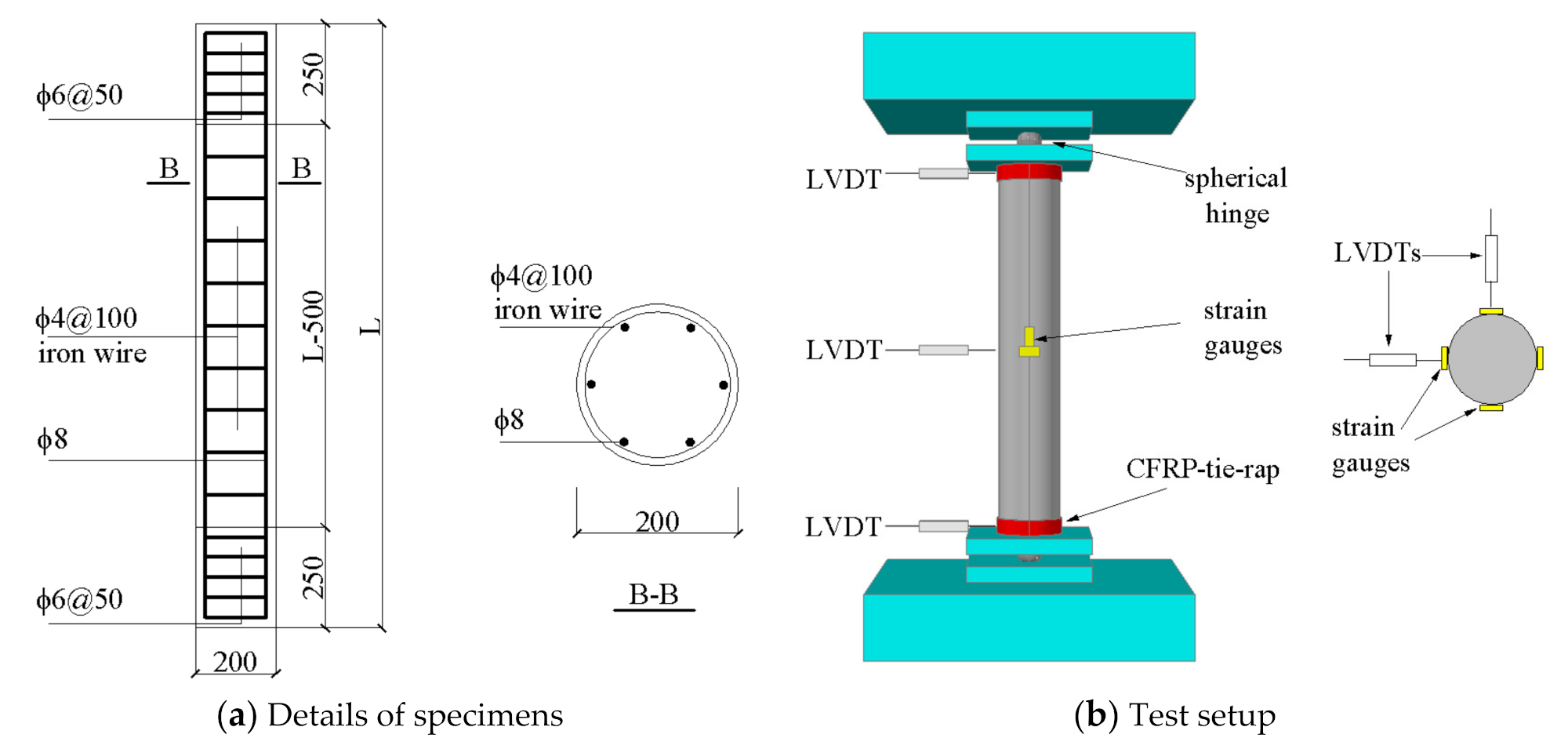
2.1. Details of Test Columns

An experiment was conducted on 6 CFRP-confined columns with a diameter of 200 mm and slenderness ratios (λ) of 12, 20, 32, 40, 48, and 56. The columns were constrained by one layer of CFRP cloth along the circumferential direction. The overlap length of CFRP was 100 mm. The thickness of concrete cover was 15 mm. The specimens were strengthened using ϕ8 mm steel bars as the longitudinal reinforcement, and 100 mm spacing of ϕ4 mm steel ties provided at the mid height region comprised the hoop reinforcement. To strengthen both ends of the column, the hoop reinforcement was changed by ϕ6 mm ties, and the spacing was reduced to 50 mm. Figure 1a shows the characteristics of the specimens. Out of CFRP-confined columns, six reference RC columns were tested without any wrapping for each slenderness ratio. Each specimen was wrapped with CFRP cloth with 50 mm width at both ends of the specimen to ensure it would fail at the mid height region.
Table 1 lists the characteristics of the test specimens. The test columns were identified by four characters. The first letter C represents a circular column. The next three numbers separated by hyphens stand for the number of CFRP layers, the slenderness ratio, and the serial number of the specimens, respectively.

2.2. Material Properties

The concrete used for casting columns was designed for a target compressive strength of 30 MPa and configured with Plain Portland cement. Medium sand was used as the fine aggregate, and pebble was used as the coarse aggregate. The diameter of coarse aggregate is 5–25 mm. The maximum aggregate size is 25 mm after screening. The mix ratio adopted was 1:0.43:1.25:2.91 (cement: water: fine aggregate: coarse aggregate). The cubic compressive strength (fcu) measured value of the same batch concretes was 32 MPa at 28 days. The cylinder strength of unconfined concrete can be calculated by f c o = 0.67 f c u = 21.44   MPa [4]. The minimum tensile strength of longitudinal steel bars was f y = 240   MPa by testing in laboratory.
The CFRP sheets were produced by TORAYCA in Japan. The measured mechanical properties of the CFRP are shown in Table 2. The CFRP was made of high strength unidirectional carbon fibers with 12,000 filaments per bundle and connected with polyamide. The epoxy adhesive was used to bond CFRP and concrete.

2.3. Testing Procedure and Instrumentation

The axial compression tests on 12 RC columns were carried out by using a pressure testing machine with a maximum capacity of 5000 kN (manufacturer is Sinotest Equipment Co., Ltd., Changchun, China). The top and bottom of the specimens were hinged. Four horizontal strain gauges and four vertical strain gauges were positioned at the half height of the specimen to measure the hoop and axial strains, respectively. Lateral deflections were recorded using three linear variable differential transformers (LVDTs) posed at both ends and the half height of the columns. As shown in Figure 1, LVDTs were placed horizontally of the columns 90 degrees around the column. The test setup and several instrumentations used for the testing of the columns are illustrated in Figure 1b.
Before testing, the columns were preloaded in the elastic range to ensure that the loading point is located at the mechanical center. The specimens were tested using gradation loading. The compressive loading was applied by an increment of 20% of the estimated specimen capacity (Nmax) before the load arrived at 60% of Nmax. Then, the loading increment was changed to 10% of Nmax. Each load level lasted 10 min. The load level was reduced gradually after reaching Nmax.

3. Experimental Results and Discussion

Table 3 summarizes the test results of the columns. Figure 2 shows the failure modes of the columns.

3.1. Unwrapped Specimens

The concrete and reinforcement of unwrapped columns behaved elastically at the initial stages of loading when the slenderness ratio (λ) of the specimens was below 40. Fine cracks were initiated at the half height of the columns with the increase of loading. When approaching the ultimate load, evident longitudinal cracks were distributed along the circumferential direction of unwrapped columns. Concrete compression crushed, and steel bars buckled at the mid length. The lateral deflection at the mid height region of the columns was small, and the failure of the specimens was caused by the axial crushing of concrete.
When the slenderness ratio (λ) of the specimens exceeded 40, at the initial stages of loading, a lateral deflection at the mid height region occurred, which could be attributed to the initial eccentricity caused by the inhomogeneity of materials or the minimal eccentricity of test loading. The concrete specimen failed due to the sudden loss of concrete cover at the compression side, and subsequent the steel bars buckled outward. Longitudinal cracks appeared at the compression side of the columns. Transverse cracks appeared at the tension side with the lateral deflection increasing rapidly. The bending failure of the specimens was caused by the high slenderness.

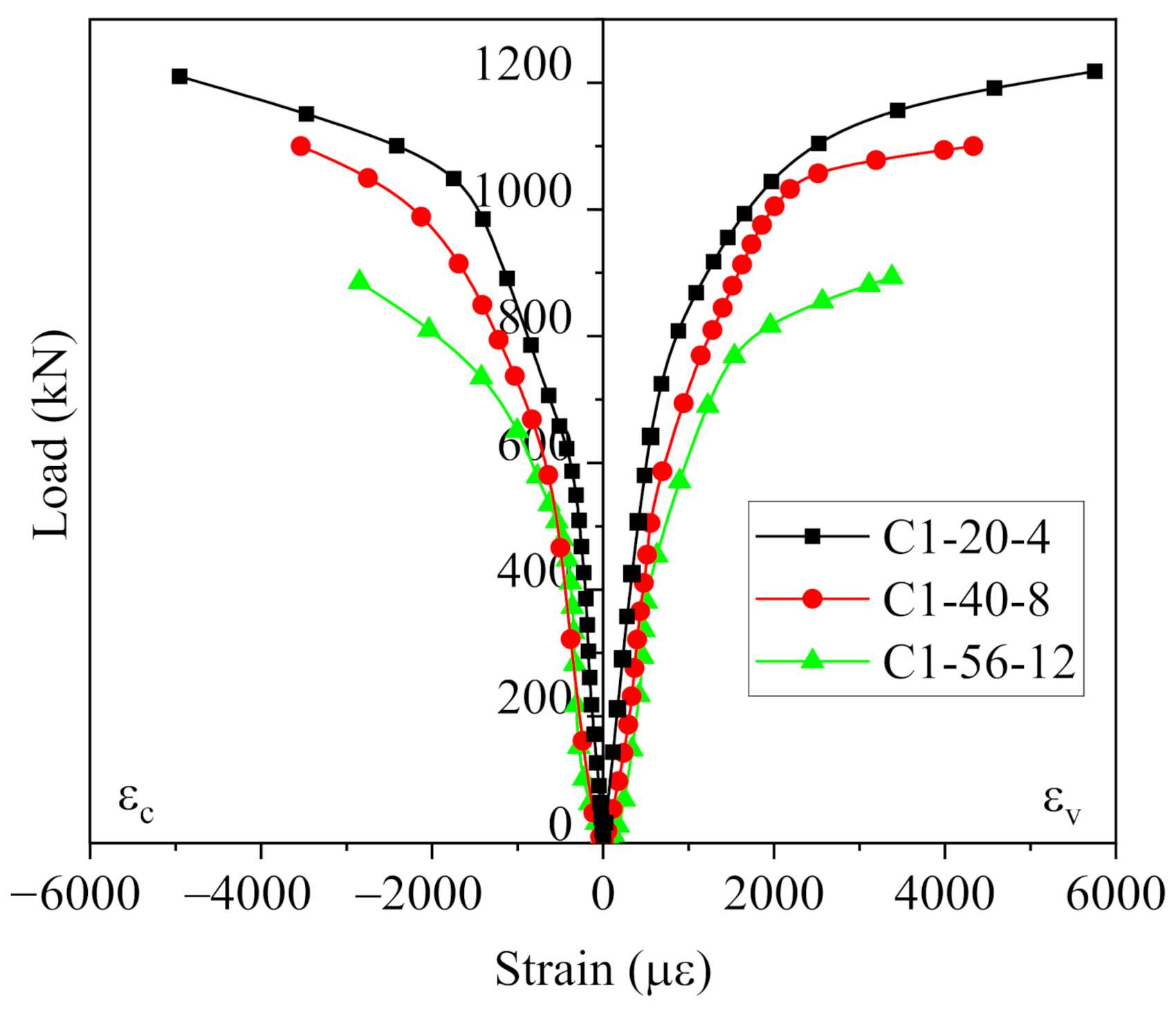
3.2. CFRP Wrapped Specimens

The failure of the CFRP-confined specimens was caused by the circumferential fracture of CFRP sheets. At loads close to the ultimate load, discontinuous crisp noises of fiber rupture were heard, which can be attributed to the debonding from the surface of the RC column. As the load increased, the debonding zone of the fiber increased, and the buckling of the steel bars intensified consequently. Specimens failed by the sudden rupture of the CFRP sheet accompanied by a loud noise. After failure of the specimens, the inner surface of CFRP sheet was stuck with concrete debris, and the tension fracture surface was serrated. Due to the circumferential constrain of FRP, the stirrups did not open or break in the failure area of the test specimens.
When the slenderness ratio (λ) of the specimens was below 32, the rupture of CFRP cloth was observed at the mid length in a wide range. The longitudinal and hoop strain of the column reached the maximum with the full play of CFRP sheets. The specimens constrained by CFRP sheets exhibited higher load-carrying capacity and ductility than the unwrapped specimens.
When the slenderness ratio (λ) of the specimens exceeded 32, at the initial stages of loading, a lateral deflection occurred at the mid height region of the columns, and exhibited a linear increase as the load increased. A nonlinear transition occurred at the load level of about 70% of the ultimate load. The lateral deflection increased sharply at loads very close to the ultimate value. When the columns failed, the longitudinal and circumferential strains of the column at the mid height region was relatively small, which indicated that the CFRP sheets did not give full play. Local compression failure was not initiated at the end of the specimens, which can be attributed to the measures of strengthening the column ends with multilayer CFRP sheets, which can effectively prevent the lack of local load capacity.
The increasing slenderness reduced the ultimate bearing capacity of slender columns, and the effect on specimens wrapped with CFRP was more remarkable than that on unwrapped columns because the dominant failure mode for slender columns was buckling failure under peak load, as shown in Table 3. The ultimate bearing capacity of unwrapped specimens and CFRP wrapped specimens moderately decreased as slenderness increased, as indicated in Figure 3. For the circular RC columns with a slenderness ratio less than 60, CFRP hoop wraps can still effectively improve the axial load-carrying capacity. As the slenderness rose from 12 to 56, the load-carrying capacity of the CFRP wrapped specimens and unwrapped specimens decreased by approximately 27% and 19%, respectively. The test results show that the influence of the slenderness on the ultimate axial load of CFRP-confined slender columns is greater compared with short columns. The strengthening effect of CFRP hoop wraps on the load-carrying capacity of short columns is better than that of slender columns, as illustrated in Figure 3. For example, as the slenderness rose from 12 to 56, the increase of ultimate load of CFRP wrapped columns is reduced from 80% to 62% compared with unwrapped columns.
To analyze the performance of slender CFRP-confined circular RC columns, the curves of load vs. deflection with different slenderness ratios were compared as shown in Figure 4. The load–deflection curve can be approximately divided into two stages. First stage is the elastic ascending stage, the slope of the first stage curves of all test columns is similar. With the increase of slenderness ratio, the columns become more unstable. When the slenderness ratio (λ) of the specimens exceeded 32, the lateral deflection of mid-height increased significantly at loads close to the ultimate value. It can be concluded that CFRP circumferential restraint cannot increase the flexural stiffness of the column. Figure 5 shows the load–strain curves of some columns. In the elastic stage, the strain increases with the increase of axial load. The influence of slenderness ratio on load–strain curve is mainly reflected in the second stage of curve. As the slenderness ratio of test specimen increases, the circumferential strain (εc) and the vertical strain (εv) of specimens decrease gradually, which indicated that the restraining effect of FRP is declined.

4. Comparisons for FRP-Confined RC Columns

Limited studies have been conducted on slender FRP-confined circular RC columns under axial load. Table 4 shows several experimental results [2,7,16,17] of FRP-confined circular RC columns to investigate the effect of slenderness on specimens.

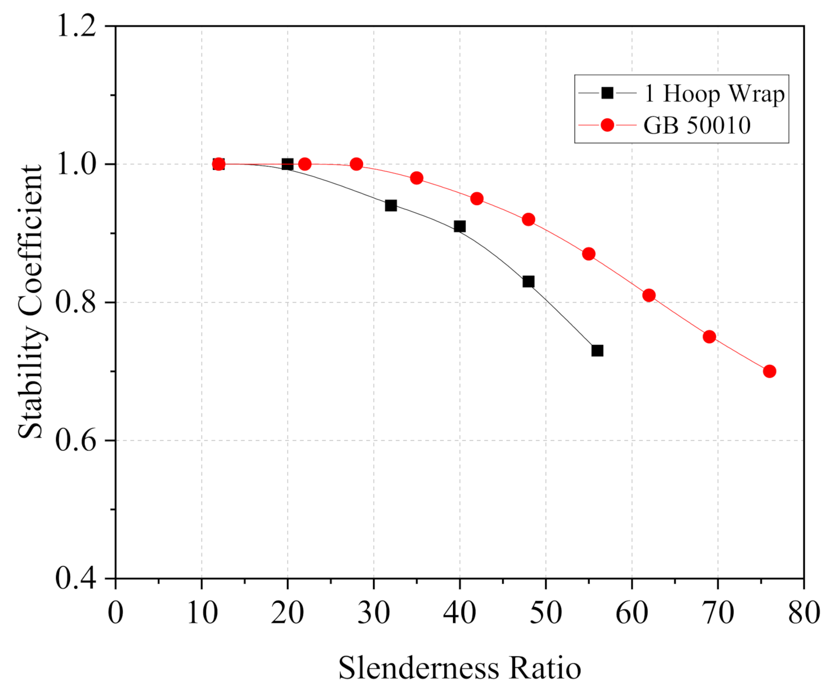
4.1. Stability Coefficient

The stability coefficient of FRP-confined RC column is defined as
φ = N u l N u b
where Nul = experimental ultimate load of slender columns, and Nub = experimental ultimate load of columns with a base slenderness of 12.
In Table 4, because there is no bearing capacity data of columns with a slenderness of 12 in group 2, group 4 and group 5, interpolation method is used to calculate the bearing capacity in group 4 and group 5. The bearing capacity of a column with a slenderness of 12 in group 2 can be calculated by the equation
N u b = f c c A g + f y A s t
f c c = f c o + 3.3 f l , a f l , a = 2 E f n t f ε f e D
where f c c = compressive strength of the FRP-confined concrete. Equation (3) is proposed by Lam and Teng [18]. All parameters are illustrated in Table 5.
Table 4 shows the stability coefficient obtained by Equation (1). The relationship between stability coefficient and slenderness ratio according to the experimental results is presented in Figure 6. By quadratic regression, the equation of stability coefficient is presented as
φ = 1.03679 0.00221 λ 0.000052 λ 2
φ = 1.46406 0.04474 λ + 0.000425 λ 2
Equation (4) is proposed according to the fitting results of three groups of experimental data, with the slenderness ratio from 12 to 56. Equation (5) is proposed according to the fitting results of two groups of experimental data, with the slenderness ratio from 12 to 37. Two different curves are shown in Figure 6 probably because the FRP type and the reinforcement ratio of longitudinal reinforcement considerably affect the stability for FRP-confined RC columns. Equation (4) is applicable to circular RC columns constrained by FRP cloth in the hoop direction, whereas Equation (5) is applicable to circular RC columns constrained by FRP tubes.
The stability coefficient between the test results and the code (GB 50010) is compared in Figure 7 [19]. The stable performance of specimens confined through lateral confinement with CFRP is slightly different from that of unwrapped RC columns. With the increasing of slenderness ratio, the stability coefficient of CFRP-confined specimens is below that of unwrapped specimens, as proposed by GB50010.

4.2. Slenderness Limit

In general, the slenderness limit for short RC columns is suggested to ignore the effect of second-order moment. ACI 318-19 [20] and CSA A23.3-14 [21] define the slenderness limit for short columns based on 5% axial load reduction, which was mainly developed by MacGregor [22]. If the slenderness ratio of columns exceeds this limit, the column should consider the effect of second-order moment.
Figure 8 shows the vertical lines to indicate the slenderness limit based on 5% axial load drop. Therefore, according to the experimental data, the slenderness limit for CFRP-confined RC columns and control columns are 26.5 and 38.6, respectively. Figure 8 also shows the slenderness ratio of 42 for RC columns that corresponds to the 5% stability coefficient reduction in GB 50010, and this slenderness limit is close to the test results of control columns.
In recent years, several design guidelines of concrete structures (e.g., ISIS Canada [23]) and researchers proposed expressions along with a safe value for the slenderness limit of FRP-confined columns. However, the existing slenderness limits are also moderately different from one another because the experimental parameters are different. Mirmiran et al. [2] recommended the slenderness limits of 22 for CFRP-confined RC columns and 11.4 for GFRP-confined RC columns. Mohamed et al. [24] suggested that the slenderness limit of 12 for steel-reinforced CFFT columns should be taken as the security value of design.
The slenderness limit of 26.5 obtained in this experiment is different from other studies. This result can be attributed to the effect of concrete compressive strength and FRP type [24]. In addition, many factors—such as initial material imperfections, accidental load eccentricities, size effect, and ratio of longitudinal reinforcement—affect the stable bearing capacity of slender FRP-confined RC columns. Further study is required to provide accurate slenderness limits for FRP-confined RC column design.

5. Analytical Prediction of Bearing Capacity

The ultimate load-carrying capacity of FRP-confined RC columns (Nup) is predicted using the equations from several design codes and guidelines (e.g., GB 50367 [25], CSA S806 [26], ACI 440 [27], and CNR DT200 [28]). These bearing capacity formulas of FRP-confined RC columns are shown in Table 5. According to the experimental results of this study, the CFRP efficiency factor ( κ ε ) is determined as 0.66, which is close to the findings of relevant research [18,29,30].
The predicted values using the bearing capacity formulas are compared with the test results as shown in Figure 9. The predicted value using the ACI formula is the most conservative of the four formulas used in this study, which can be attributed to its consideration of the effect of accidental eccentricity.
Figure 9 also shows that the predicted values rarely considered the influence of slenderness ratio. Therefore, the ultimate load-carrying capacity of FRP-confined RC columns (Nuc) can be calculated by introducing a stability coefficient to consider the slenderness effect. On the basis of the experimental results and the design equations of GB 50367, the formula is
N u c = 0.9 φ f c 0 + 4 σ l A c o r + f y 0 A s 0
where φ can be calculated using Equations (4) and (5) depending on the type of FRP.
According to the calculate results, this formula is more accurate to predict the load-carrying capacity of specimens wrapped with FRP cloth. The calculated values of ultimate load-carrying capacity formula and the results of the experiment are compared in Figure 10 to evaluate the accuracy of the proposed formula. The percentage difference between the predicted ultimate load-carrying capacity (Nuc) and the test values of specimens wrapped with FRP cloth is less than 15%. Accordingly, the proposed formula could provide a relatively correct prediction for the load-carrying capacity of the columns tested in this study. The applicability of the formula needs to be confirmed further by more relevant experimental data.

6. Discussion

In this paper, the behavior of CFRP-confined circular RC columns under axial load is investigated. The main parameter considered is the slenderness. Indeed, various parameters including geometric/material imperfections in the column, fiber types, and initial load eccentricities can affect the behavior of axially loaded FRP-confined RC columns. Moreover, whether a substantial size effect on slender columns with FRP wrapped is unclear. Therefore, additional research is needed to verify the effectiveness of the proposed expressions and provide reasonable predictions for design purposes.

7. Conclusions

The following conclusions are obtained based on the results and comparisons of this study.
  • The ultimate axial load of CFRP wrapped columns moderately decreases as slenderness increases. For the circular RC columns with a slenderness ratio less than 60, CFRP hoop wraps can still effectively improve the axial load-carrying capacity.
  • The ultimate axial load of CFRP-wrapped specimens and unwrapped specimens decreases by approximately 27% and 19% when the slenderness ratio increases from 12 to 56, respectively.
  • On the basis of the present study, the limit value of slenderness ratio of 26.5 is proposed for CFRP-confined circular RC columns. Slenderness effects can be neglected if the slenderness ratio of the columns is below this limit.
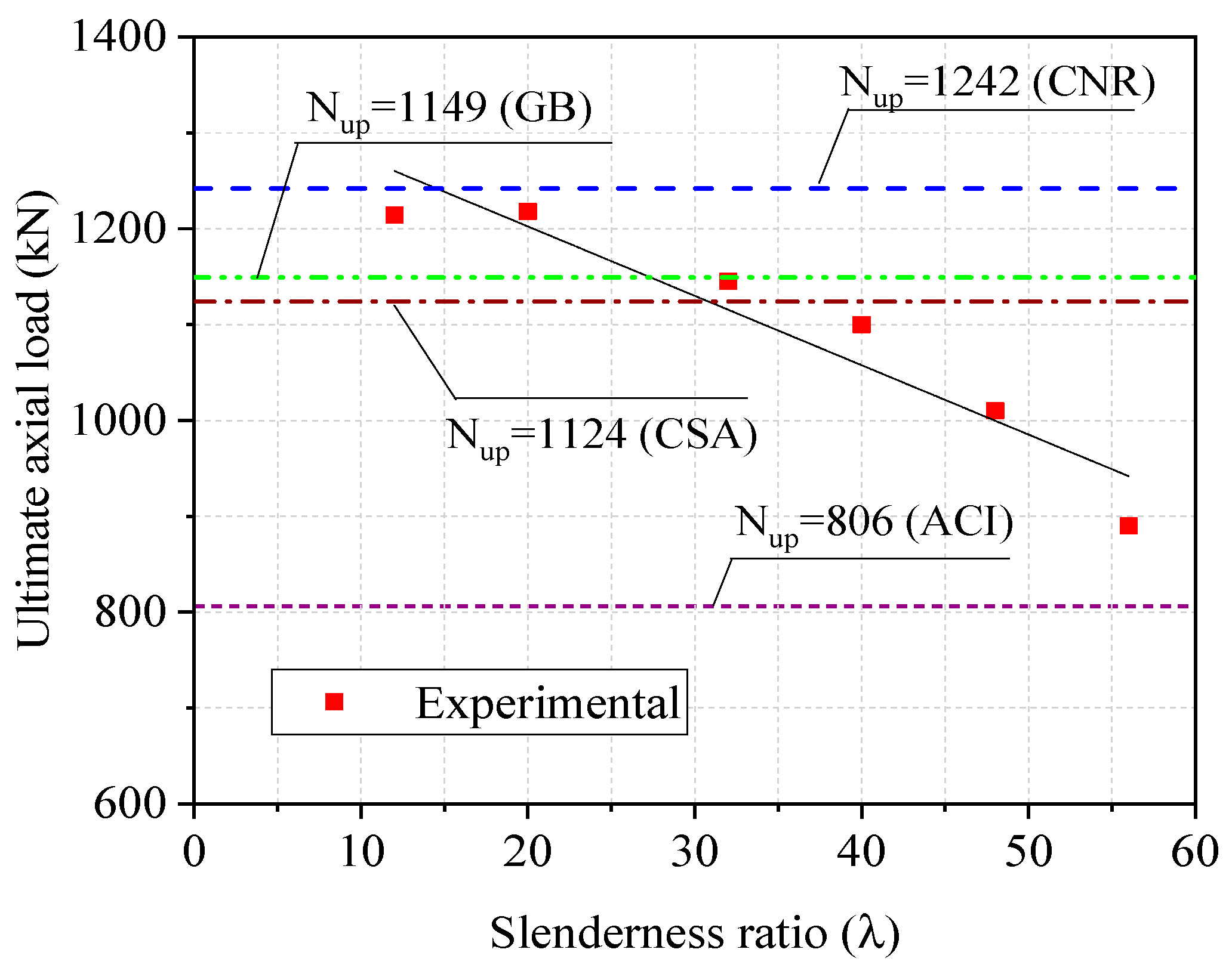
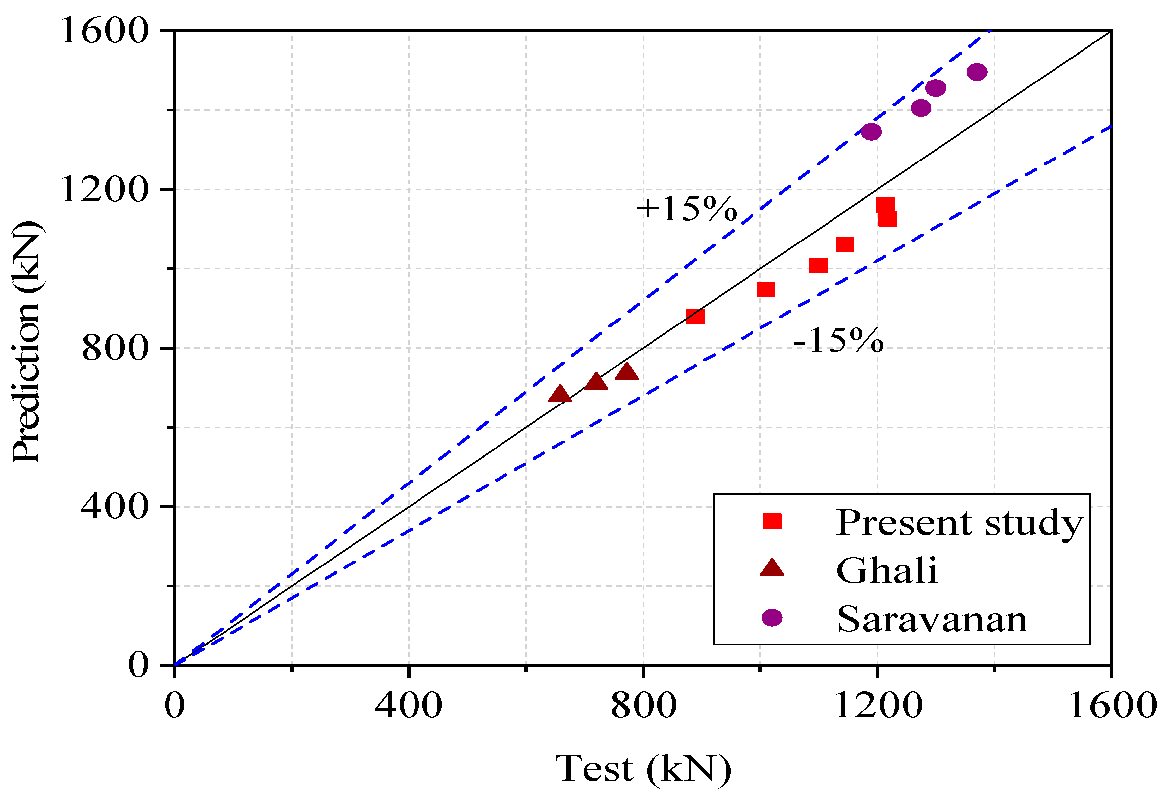
  • According to the equations of GB 50367, CSA S806, ACI 440, and CNR DT200, the axial load predictions of specimens are compared with test results. In the range of the slenderness ratio of the present study, ACI 440 can provide conservative predictions for the ultimate axial load of the test columns.
  • A modified equation is proposed to estimate the ultimate load-carrying capacity of CFRP-confined circular RC columns. The calculated values of ultimate load capacity agree with the experimental results by introducing the stability coefficient into the equation. The applicability of the above formula needs to be confirmed further by more research due to the limited experimental data.

Author Contributions

Conceptualization, investigation, H.Y.; writing—original draft preparation, data curation, Q.L.; supervision and review, Z.H.; formal analysis, software, Y.W. All authors have read and agreed to the published version of the manuscript.

Funding

This research received no external funding.

Institutional Review Board Statement

Not applicable.

Informed Consent Statement

Not applicable.

Data Availability Statement

The data used to support the findings of this study are available from the first author or the corresponding author upon request.

Conflicts of Interest

The authors declare no conflict of interest regarding the publication of this paper.

References

  1. Youcef, Y.S.; Amziane, S.; Chemrouk, M. Effectiveness of strengthening by CFRP on behavior of reinforced concrete columns with respect to the buckling instability. Mater. Struct. 2015, 48, 35–51. [Google Scholar] [CrossRef]
  2. Mirmiran, A.; Shahawy, M.; Beitleman, T. Slenderness Limit for Hybrid FRP-Concrete Columns. J. Compos. Constr. 2001, 5, 26–34. [Google Scholar] [CrossRef]
  3. Fitzwilliam, J.; Bisby, L.A. Slenderness effects on circular CFRP confined reinforced concrete columns. J. Compos. Constr. 2010, 14, 280–288. [Google Scholar] [CrossRef]
  4. Jiang, T.; Teng, J.G. Slenderness limit for short FRP-confined circular RC columns. J. Compos. Constr. 2012, 16, 650–661. [Google Scholar] [CrossRef]
  5. Chikh, N.; Benzaid, R.; Mesbah, H. An Experimental Investigation of Circular RC Columns with Various Slenderness Confined with CFRP Sheets. Arab. J. Sci. Eng. 2012, 37, 315–323. [Google Scholar] [CrossRef]
  6. Jiang, T.; Teng, J.G. Behavior and design of slender FRP-confined circular RC columns. J. Compos. Constr. 2013, 17, 443–453. [Google Scholar] [CrossRef] [Green Version]
  7. Abdallah, M.H.; Mohamed, H.M.; Masmoudi, R. Experimental assessment and theoretical evaluation of axial behavior of short and slender CFFT columns reinforced with steel and CFRP bars. Constr. Build. Mater. 2018, 181, 535–550. [Google Scholar] [CrossRef]
  8. Xing, L.; Lin, G.; Chen, J.F. Behavior of FRP-Confined Circular RC Columns under Eccentric Compression. J. Compos. Constr. 2020, 24, 04020030. [Google Scholar] [CrossRef]
  9. Rocca, S.; Galati, N.; Nanni, A. Large-size reinforced concrete columns strengthened with carbon FRP: Validation of existing design guidelines. In Proceedings of the 3rd International Conference on Composites in Civil Engineering, CICE 2006, Miami, FL, USA, 13–15 December 2006; pp. 231–234. [Google Scholar]
  10. Issa, M.A.; Alrousan, R.Z.; Issa, M.A. Experimental and parametric study of circular short columns confined with CFRP composites. J. Compos. Constr. 2009, 13, 135–147. [Google Scholar] [CrossRef]
  11. Thériault, M.; Neale, K.W.; Claude, S. Fiber-Reinforced Polymer-Confined Circular Concrete Columns: Investigation of Size and Slenderness Effects. J. Compos. Constr. 2004, 8, 323–331. [Google Scholar] [CrossRef]
  12. Masia, M.J.; Gale, T.N.; Shrive, N.G. Size effects in axially loaded square section concrete prisms strengthened using carbon fiber reinforced polymer wrapping. Can. J. Civ. Eng. 2004, 31, 1–13. [Google Scholar] [CrossRef]
  13. Hadi, M.N.S. Behaviour of eccentric loading of FRP confined fibre steel reinforced concrete columns. Constr. Build. Mater. 2009, 23, 1102–1108. [Google Scholar] [CrossRef] [Green Version]
  14. Li, J.; Hadi, M.N.S. Behaviour of externally confined high-strength concrete columns under eccentric loading. Compos. Struct. 2003, 62, 145–153. [Google Scholar] [CrossRef]
  15. Bisby, L.; Ranger, M. Axial–flexural Interaction in Circular FRP-Confined Reinforced Concrete Columns. Constr. Build. Mater. 2010, 24, 1672–1681. [Google Scholar] [CrossRef]
  16. Ghali, K.N.; Rizkalla, S.H.; Kassem, M.A.; Fawzy, T.; Mahmoud, M.H. FRP-confined circular columns under small eccentric loading. In Proceedings of the 5th Alexandria International Conference on Structural and Geotechnical Engineering, Alexandria, Egypt, 20–27 December 2003; pp. 20–22. [Google Scholar]
  17. Saravanan, J.; Suguna, K.; Raghunath, P.N. Slenderness effect on high strength concrete columns confined with GFRP wraps. Indian J. Eng. Mater. Sci. 2014, 21, 67–74. [Google Scholar]
  18. Lam, L.; Teng, J.G. Design-oriented stress–strain model for FRP-confined concrete. Constr. Build. Mater. 2003, 17, 471–489. [Google Scholar] [CrossRef]
  19. GB (Code of China). Code for Design of Concrete Structures; GB 50010; China Planning Press: Beijing, China, 2010. [Google Scholar]
  20. ACI (American Concrete Institute). Building Code Requirements for Structural Concrete; ACI 318-19; ACI: Farmington Hills, MI, USA, 2019. [Google Scholar]
  21. CSA (Canadian Standards Association). Design of Concrete Structures; CSA A23.3-14; CSA: Rexdale, ON, Canada, 2014. [Google Scholar]
  22. MacGregor, J.G.; Breen, J.E. Design of slender concrete columns. ACI J. 1970, 67, 6–28. [Google Scholar]
  23. ISIS (Intelligent Sensing for Innovative Structures) Canada. Design Manual Number 4: Strengthening Reinforced Concrete Structures with Externally-Bonded Fiber Reinforced Polymers; ISIS: Winnipeg, MB, Canada, 2001. [Google Scholar]
  24. Mohamed, H.M.; Abdel-Baky, H.M.; Masmoudi, R. Nonlinear Stability Analysis of Concrete-Filled Fiber-Reinforced Polymer-Tube Columns: Experimental and Theoretical Investigation. ACI Struct. J. 2010, 107, 699–708. [Google Scholar]
  25. GB (Code of China). Code for Design of Strengthening Concrete Structure; GB 50367; China Planning Press: Beijing, China, 2013. [Google Scholar]
  26. CSA (Canadian Standards Association). Design and Construction of Building Components with Fibre Reinforced Polymers; CSA S806-12; CSA: Mississauga, ON, Canada, 2012. [Google Scholar]
  27. ACI (American Concrete Institute). Guide for the Design and Construction of Externally Bonded FRP Systems for Strengthening Concrete Structures; ACI 440.2R-17; ACI: Farmington Hills, MI, USA, 2017. [Google Scholar]
  28. CNR (National Research Council). Guide for the Design and Construction of Externally Bonded FRP Systems for Strengthening Existing Structures; CNR DT200-2013; CNR: Rome, Italy, 2013. [Google Scholar]
  29. Kaeseberg, S.; Messerer, D.; Holschemacher, K. Experimental Study on Concrete under Combined FRP–Steel Confinement. Materials 2020, 13, 4467. [Google Scholar] [CrossRef] [PubMed]
  30. Tang, Z.; Li, W.; Tam, V.W.Y.; Yan, L. Mechanical performance of CFRP-confined sustainable geopolymeric recycled concrete under axial compression. Eng. Struct. 2020, 224, 111246. [Google Scholar] [CrossRef]
Figure 1. Details of specimens and overview of test setup.
Applsci 11 03968 g001
Figure 2. Failure mode of tested columns.
Applsci 11 03968 g002
Figure 3. Ultimate axial load versus slenderness ratios relationships.
Applsci 11 03968 g003
Figure 4. Load vs. deflection curve.
Applsci 11 03968 g004
Figure 5. Load vs. strain curve.
Applsci 11 03968 g005
Figure 6. Effect of slenderness on the stability coefficient.
Applsci 11 03968 g006
Figure 7. Stability coefficient versus slenderness curves.
Applsci 11 03968 g007
Figure 8. Effect of slenderness on ultimate axial load.
Applsci 11 03968 g008
Figure 9. Comparison between the predicted values and experimental results.
Applsci 11 03968 g009
Figure 10. Prediction versus test ultimate load capacity.
Applsci 11 03968 g010
Table 1. Characteristics of test specimens.
SpecimensSlenderness Ratiofcu (MPa)L (mm)D (mm) CFRP layersReinforcement
C-0-12-1123260020006ϕ8
C-1-12-2123260020016ϕ8
C-0-20-32032100020006ϕ8
C-1-20-42032100020016ϕ8
C-0-32-53232160020006ϕ8
C-1-32-63232160020016ϕ8
C-0-40-74032200020006ϕ8
C-1-40-84032200020016ϕ8
C-0-48-94832240020006ϕ8
C-1-48-104832240020016ϕ8
C-0-56-115632280020006ϕ8
C-1-56-125632280020016ϕ8
Table 2. Mechanical properties CFRP and epoxy adhesive.
MaterialThickness,
tf (mm)
Density
(g/m2)
Tensile Strength,
ffu (MPa)
Elastic Modulus,
Ef (MPa)
Fracture Strain,
εfu (%)
CFRP0.1673004330237,0001.7
epoxy adhesive 41.130681.57
Table 3. Summary of test results.
SpecimensSlenderness RatioUltimate Load (kN) SpecimenSlenderness RatioUltimate Load (kN)
C-0-12-112675C-1-12-2121214
C-0-20-320665C-1-20-4201218
C-0-32-532699C-1-32-6321145
C-0-40-740660C-1-40-8401100
C-0-48-948630C-1-48-10481010
C-0-56-1156550C-1-56-1256890
Table 4. Summary of test results of FRP-confined circular RC columns.
No.SpecimensH (mm)D (mm)L/Dλfco′ (MPa)ffu (MPa)Ef (GPa)εfutf (mm)fy (MPa)As′ (mm2)Nu (kN)φTypeReference
1C-1-12-260020031221.443302370.0170.167240302
(6ϕ8)
12141.0CFRP clothPresent study
C-1-20-4100052012181.0
C-1-32-6160083211450.94
C-1-40-82000104011000.91
C-1-48-102400124810100.83
C-1-56-12280014568900.73
2G1-1C610150416203500233.3330.0150.16365392.317720.98 CFRP clothGhali [16]
G2-1C9156247200.92
G3-1C12208326580.84
38-S-I610152483034520.6900.0122.65460471
(6ϕ10)
1652-GFRP tubeAbdallah [7]
12-S-I91261214541.00
16-S-I121681612020.83
20-S-I1500102011270.78
4S8G-33001502842.6446.913.9650.03023450302
(6ϕ8)
1370-GFRP clothSaravanan [17]
S16G-360041613000.97
S24G-390062412750.96
S32G-3120083211900.89
5RC-1305147.32.1422.4218669.6400.0313.68--1659.1-GFRP tubeMirmiran [2]
RC-28135.5111362.2-
RC-313729.3181026.50.78
RC-4165111.222837.70.64
RC-5228615.531648.60.49
RC-6259117.635.25920.45
RC-7274318.637.2475.20.36
Table 5. Comparisons of bearing capacity formulas in concrete structure design codes.
CodesBearing Capacity FormulasComments
GB 50367-2013 N 0.9 f c 0 + 4 σ l A c o r + f y 0 A s 0 σ l = 0.5 β c k c ρ f E f ε f e
ρ f = 4 n t f / D
CSA S806-12 P 0 = α 1 f c c A g A s t + f y A s t f c c = 0.85 f c + k l k c 1 f l
α 1 = 0.85 0.0015 f c 0.67
k l = 6.7 k c 1 f l 0.17
f l = 2 n t F f F / D ; f F = ε f e E f
ACI 440.2R-17 P n , max = 0.8 0.85 f c c A g A s t + f y A s t f c c = f c + ψ f 3.3 κ a f l
f l = 2 E f n t f ε f e D ; ε f e = κ ε ε f u
CNR DT200-2013 N R c c , d = 1 γ R d A c f c c d + f y d A s f c c d f c d = 1 + 2.6 f l , e f f f c d 2 / 3
f l , e f f = 1 2 ρ f E f ε f d , r i d ; ε f d , r i d = κ ε ε f k
Note: N , P 0 , P n , m a x , N R c c , d = factored axial capacity; f c c , f c c d = confined concrete compressive strength; f c , f c 0 , f c d = unconfined cylinder compressive strength of concrete; f y , f y 0 , f y d = specified yield strength of steel reinforcement; A s t , A s 0 , A s = total area of longitudinal reinforcement; A g , A c , A c o r = gross area of concrete section; σ l , f l , f l , e f f = effective confinement pressure; ρ f = geometric strengthening ratio; β c = influence coefficient of concrete strength taken as 1.0; k c , k c 1 , κ a = confinement efficiency factor for circular columns, taken as 0.95,1.0,1.0 respectively; E f , E F = modulus of elasticity of FRP; ε f e , ε f d , r i d = effective strain in FRP reinforcement; t f , t F = thickness of one ply of FRP; n = number of plies of FRP; D = diameter of circular columns; f F = stress in FRP composite; f F u = ultimate tensile strength of FRP composite; α 1 = ratio of average stress in rectangular compression block to the specified concrete strength; ψ f = FRP strength reduction factor taken as 0.95; γ R d = partial factor taken as 1.10; ε f e = effective strain in FRP; κ ε = efficiency factor for FRP strain; ε f u , ε f k = ultimate strain of FRP reinforcement.
Publisher’s Note: MDPI stays neutral with regard to jurisdictional claims in published maps and institutional affiliations.

