Abstract
A technique for strengthening masonry walls by plastering with amorphous steel fiber-reinforced mortar (ASFRM) is investigated through compressive and diagonal tension tests for masonry prisms. The vertical joint between masonry units was not completely filled with mortar to mimic poor workmanship, which is typically reflected in low-cost buildings. The test variables include the number and thickness of mortar overlays, fiber volume fraction, and additional reinforcement using glass fiber mesh or shear connectors. In most strengthened specimens, the ASFRM is not damaged but separated from the masonry prisms after its maximum strength is reached. Additional tests for the bond strength between the ASFRM overlay and masonry surface are conducted to evaluate its contribution to the strengthening effects. Based on experimental observations, equations for predicting the compressive and diagonal tension strengths of masonry prisms strengthened with ASFRM are proposed. The compressive strength can be predicted more accurately by considering the asymmetrical distribution of compressive stress when strengthening is performed on only one side. The diagonal tension strength after strengthening can be predicted by incorporating the contribution of the bond strength between the ASFRM overlay and masonry prism to the initial strength.
1. Introduction
Unreinforced masonry is a representative structural component that is vulnerable to earthquakes. Significant structural damage and collapse of masonry buildings accompanied by significant property loss and casualties were observed in many past earthquake events [1,2]. One reason for such severe damage is that many masonry buildings are composed of unreinforced masonry walls, as these buildings were designed before the establishment of seismic design codes or are exempted from seismic design requirements owing to their relatively small sizes. Masonry supports gravity loads effectively by its compressive strength but cannot sustain combined stresses owing to its low tensile strength and brittle behavior. Diverse modeling techniques have been developed for unreinforced masonry structures using refined finite elements or macro-elements [3]. In addition, innovative survey techniques using 3D laser scanning or digital photogrammetry have been developed and combined with seismic performance assessment based on the finite element modeling [4,5].
Considering the vulnerability of unreinforced masonry buildings is necessary; however, a retrofit technique that enables a low-cost and short duration construction is required to promote the voluntary retrofit of such buildings, which are typically privately owned. Among the many retrofit techniques for masonry buildings, strengthening masonry walls by attaching or plastering reinforcement materials such as fiber-reinforced polymer (FRP) or mortar reinforced with a fiber mesh is advantageous in that implementation can be performed outside the building, thereby enabling retrofitting while the buildings are occupied.
Yang et al. [6] tested masonry walls strengthened with glass fiber grids and prestressed steel bars subjected to cyclic loading. Ismail et al. [7] tested masonry wallettes reinforced with twisted steel bars inserted in grooves formed on mortar joints or brick surfaces and evaluated the improvement in ductility. Silva et al. [8] verified the strength and ductility of unreinforced masonry strengthened with lime grout injection. Taghdi et al. [9] and Darbhanzi et al. [10] attached steel strips to existing masonry walls in a diagonal or vertical direction and anchored their ends to adjacent existing structural components. Ghiassi et al. conducted both numerical and experimental studies on the bond-slip behavior of FRP materials for strengthening masonry [11]. Bae et al. [12] conducted cyclic loading tests on masonry walls strengthened with FRP sheets. Choi et al. [13] sprayed engineered cementitious composites reinforced with polyvinyl alcohol fibers on masonry walls and observed an increase in the strength and ductility under cyclic loading. In addition, D’Ambrisi et al., Almeida et al., Mustafaraj et al. and Benedetti [14,15,16,17] investigated diverse strengthening techniques for masonry walls by plastering high-strength mortar or mortar reinforced with diverse fibers or meshes such as carbon fiber mesh, polymeric net, and glass fiber reinforced polymer mesh. Krevaikas, and Ombres and Verre investigated confinement effect obtained with fabric reinforced cementitious mortar jackets for masonry columns experimentally and proposed methods to predict enhanced axial strengths [18,19].
This study investigates the performance and key mechanical properties of masonry strengthened with an amorphous steel fiber-reinforced mortar (ASFRM) overlay. Among the various fibers used in concrete or mortar mixtures, amorphous steel (AS) fibers are adopted because of their superior bonding characteristics and relatively short and thin shapes, which are suitable for plastering small thicknesses. Although existing studies have typically utilized mortar overlays reinforced with grid-type meshes, only AS fibers are used as the main reinforcement material in this study. The mesh can be excluded because steel fibers exhibit high strength and stiffness compared with organic fibers such as polyethylene (PE) and polypropylene. Hence, the installation of the proposed ASFRM overlay can be completed via merely plastering and is easier to accomplish around the opening compared with the installation of meshes.
In previous studies by the authors, a recommended mixing ratio for an ASFRM was derived, and the corresponding strengthening effects were demonstrated for masonry prisms, which were created with good workmanship, i.e., both bed and head joints were filled compactly with mortar [20]. However, in actual bricklaying, sufficient mortar is spread on the bed joints only, and efforts to fill head joints are insufficient. In this study, masonry prisms in hollow red clay bricks whose head joints were intentionally not filled were strengthened and tested to reproduce the bricklaying practice. Various test variables were considered, including the number and thickness of mortar overlays, fiber volume fraction, and additional reinforcement using mesh or shear connectors. In addition, tests for the bond strength between the ASFRM overlay and masonry surface were conducted to evaluate the contribution of the bond strength to the diagonal tension strength. The test results were combined with other experimental results of masonry in solid concrete bricks reported by Yu et al. [21,22] to derive design equations for the compressive and diagonal tension strengths. The design equations consider the asymmetrical stress distribution and the contribution of bond strength to the compressive strength based on experimental observations.
The remainder of this paper is organized as follows: First, a test program including the experimental setup, material properties, and specimen characteristics is described. Second, the test results for compressive, diagonal tension, and bond strengths are described in terms of improved strength and damage characteristics. Third, design equations to predict enhanced strength are proposed based on experimental observations and verified with the test results. Finally, strength modification factors based on the statistics of the test results are presented.
2. Experimental Program
Tests for the compressive and diagonal tension strengths of hollow red clay brick masonry prisms were conducted to investigate the strengthening effects of the ASFRM. In addition, the bond strength at the interface of the ASFRM overlay and masonry layer was measured to evaluate the contribution of the bond strength to the diagonal tension strength. The test setup, test variables, and preparation of the specimens are described in this section.
2.1. Test Setup and Instrumentation
2.1.1. Test for Compressive and Diagonal Tension Strength
Tests for the compressive and diagonal tension strengths of masonry prisms were conducted in accordance with ASTM C1314 and ASTM E519 [23,24]. The test setup comprising a universal testing machine for the compressive strength and diagonal tension strength is shown in Figure 1a,b, respectively. For diagonal tension strength tests, V-shaped zigs satisfying the requirements of ASTM E519 were used to support a masonry prism rotated by 45° at the top and bottom. The monotonic loading protocol was applied with displacement control at 1 and 0.6 mm/min for the compressive and diagonal tension strength tests, respectively. Monotonic loading was terminated when the resistance of the specimen decreased to less than 70% of the peak.
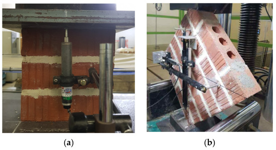
Figure 1.
Test setup for determining strengths of masonry prisms: (a) Compressive strength; (b) diagonal tension strength.
The compressive deformation of the prism was measured using linear variable displacement transducers (LVDTs) installed on the front and back of the specimens in compressive strength tests. Vertical and horizontal deformations were measured using LVDTs attached to the front and back of the specimens in the diagonal tension tests. Deformations were measured at the front and back of the specimens and averaged. The compressive and diagonal tension strengths as well as the elastic and shear moduli were calculated in accordance with ASTM C1314 and ASTM E519, as described by Yu et al. [21].
2.1.2. Test for Bond Strength
The test setup to determine the bond strength at the interface between the ASFRM overlay and masonry layer is illustrated in Figure 2. The test specimen was the same prism used in the tests for the compressive strength; however, the specimen was set up with bed joints in the vertical direction. The masonry unit in the middle of the prism was loaded by pushing downward, and supports were installed below both the left- and right-hand side masonry units in the specimen. For the strengthened specimen, vertical loading was applied only to the masonry unit to avoid loading the ASFRM overlay directly.
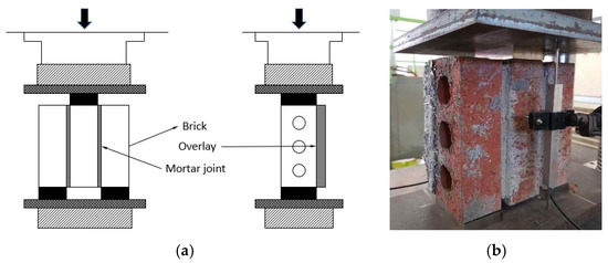
Figure 2.
Test setup for determining bond strength between masonry layer and ASFRM overlay: (a) Loading scheme; (b) Instrumentation.
2.2. Test Variables and Characteristics of Specimens
2.2.1. Test for Compressive and Diagonal Tension Strengths
The test program used to investigate the strengthening effects of the ASFRM overlay in terms of the compressive and diagonal tension strengths is summarized in Table 1. The meaning of the notations used for the specimens is provided in the footnote of Table 1. Various test variables were considered to investigate the overlay and installation details more comprehensively for strengthening the red clay hollow brick masonry. The basic test variables were the number of sides strengthened with the ASFRM on masonry prisms (one or both sides) and the thickness of the mortar overlay (20 or 30 mm). The glass fiber mesh used by Almeida et al. [15] was applied to a number of specimens, of which some were reinforced with glass fiber mesh only (D-NM-30S and D-NM-30B), whereas others were reinforced with both AS fibers and glass fiber mesh (D-SFM-30S and B, D-SFM-30S). Although AS fibers were applied to most specimens as a reinforcement material for mortar overlays, PE fibers combined with a glass fiber mesh used in Lee et al. (2008) [25] replaced AS fibers in some specimens to perform a comparison (D-PEM-30S and D-PEM-30B). In addition, shear connectors were installed at the interface between the ASFRM overlay and masonry layer for a number of specimens under diagonal tension tests to provide additional resistance in addition to bond strength of the strengthening mortar (D-SFA-30S and D-SFA-30B). Commercially available screw bolts were adopted for the shear connector, and four screw bolts per overlay-to-masonry interface were installed in drilled holes and filled with epoxy resin.

Table 1.
Test program and specimens.
2.2.2. Test for Bond Strength
The test program to determine the bond strength between the ASFRM overlay and masonry layer is summarized in Table 2. The expected plane of bond failure in the specimen strengthened with the ASFRM overlay set, as shown in Figure 2, included a mortar bed joint between masonry units; this is because the compressive force exerted on the middle masonry unit was transferred to the supports through both the bed joint and overlay-to-masonry interface. Therefore, masonry prisms without ASFRM overlays were included in the specimens to measure the bed joint shear strength between the masonry units.
Table 2.
Test program and specimen for bond strength tests.
2.3. Preparation of Specimens
2.3.1. Mixing Ratio of ASFRM
The mixing ratio of the fiber-reinforced mortar (FRM) is listed in Table 3. The properties of the AS fiber were those reported by Yu et al. [20]. The mixing ratio of the ASFRM used in this study was based on previous experimental studies. Yu et al. recommended a mixing ratio that considers both strength and suitability for performing plastering based on flow tests, suitability tests for plastering, and compressive and tensile strength tests [20]. Regarding the mixing ratio of polyethylene fiber-reinforced mortar (PEFRM), the fiber volume fraction is the same as that of the ASFRM, and the water-to-cement ratio is based on the suitability test for plastering, similar to that of the ASFRM. The mechanical properties of both types of FRMs are provided in Table 3. The strength and elastic modulus of the ASFRM were higher than those of the PEFRM. In particular, the tensile strength was doubled by using AS fibers compared with using PE fibers.
Table 3.
Mixing ratio and properties of fiber reinforced mortar [22].
2.3.2. Masonry Prisms
Masonry prisms for conducting compressive and diagonal tension strength tests were created in accordance with ASTM C1314 and ASTM E519, respectively, as illustrated in Figure 3. Hollow red clay bricks have an average compressive strength of 25.8 MPa. The cement-to-sand ratio of mortar for joints between masonry units is 1:5, which was adopted considering construction field practice in Korea, although 1:3 is prescribed in the Korean Construction Specifications [26]. The average 28-day compressive strength of the joint mortar was 10.5 MPa.
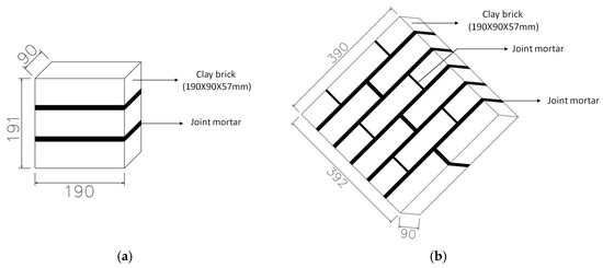
Figure 3.
Masonry prism specimens: Prism for (a) compression test and (b) diagonal tension test.
In the Korean construction practice of bricklaying, there is a lack of efforts to fill head joints with mortar. Therefore, filling the head joints with mortar was intentionally avoided to reproduce the bricklaying practice. In addition, the mortar was spread on only half of the area of the bed joint. After completing the bricklaying, the joints on the front side of the masonry prism were filled with finishing mortar, whereas the other side was not, as observed from field practice for exterior masonry walls, because the inside of the outer wall faces an insulator in most buildings and has no additional finishing.
2.3.3. Strengthened Masonry Prisms
Strengthened masonry prisms were created by plastering the ASFRM 28 d after the completion of bricklaying. The ASFRM was plastered three times with an interval of 24 h until a target thickness of 20 or 30 mm was achieved. Before each plastering, a sufficient amount of water was sprayed onto the surface of the specimen. Primer in plain mortar was plastered and roughened to enhance bond between the masonry layer and ASFRM. The process of implementing proposed strengthening technique to masonry prism specimens is illustrated in Figure 4a–d. More information regarding the implementation of the ASFRM overlay is available in Yu et al. (2021) [21]. The PEFRM was plastered on masonry prisms in the same manner as the ASFRM. For specimens with glass fiber mesh, the mesh was embedded by plastering ASFRM over as shown in Figure 4e. For specimens with shear connectors, the shear connectors were installed in four drilled holes with an embedment depth of 20 mm using epoxy resin. Steel screws with head and shank diameters of 10 and 6 mm, respectively, were installed in four drilled holes with an embedment depth of 20 mm using epoxy resin, then ASFRM was plastered as shown in Figure 4f. Strengthening was conducted on the 28th day after bricklaying was completed. All tests were performed 28 d after strengthening.
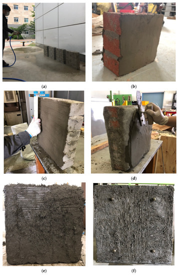
Figure 4.
Implementation of strengthened masonry prisms: (a) Wetting bare prisms; (b) Plastering plain mortar primer; (c) Roughening the plain mortar primer using wire brush; (d) Plastering ASFRM on the mortar primer; (e) Implementing additional mesh by plastering ASFRM; (f) Masonry prisms with shear connectors after the primary plastering of ASFRM.
3. Test Results
3.1. Test for Compressive Strength
The stress–strain curves obtained from the tests for compressive strength are plotted in Figure 5. The compressive strength and elastic modulus based on the stress–strain curves are summarized in Table 4. All the stresses in the strengthened specimen were calculated based on the cross-sectional area of the bare masonry prism for a consistent comparison. The average compressive strength and elastic modulus for the bare prisms were 11.9 and 1780 MPa, respectively. The compressive strength increased to 14.5 MPa (22% increase) for C-SF-30S strengthened on one side with a 30 mm ASFRM overlay, and 29.8 MPa (150% increase) for C-SF-30B strengthened on both sides with the same overlay thickness. The effect of the symmetrical strengthening scheme was more than double that of the added cross-sectional area. Similarly, increasing the thickness of the ASFRM overlay from 20 to 30 mm enhanced the compressive strength more effectively when overlays were applied to both sides of the prism. It can be presumed that the uneven distribution of normal stress in the cross section due to unsymmetrically plastered ASFRM resulted in low efficiency of strengthening, which will be addressed in derivation of design equations later. By adding glass fiber mesh to the ASFRM overlay, the compressive strength increased by 2.4 MPa for strengthening on one side but decreased by 7.3 MPa for strengthening on both sides; therefore, the glass fiber mesh did not yield a consistent positive effect. The overall tendency of improvement in the elastic modulus was similar to that in the compressive strength. Hence, it is unnecessary to use both the AS fiber and glass fiber mesh together.
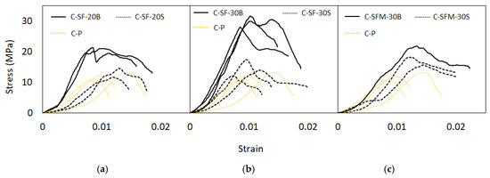
Figure 5.
Compressive stress–strain curve: (a) C-SF-20S and C-SF-20B; (b) C-SF-30S and C-SF-30B; (c) C-SFM-30S and C-SFM-30B.
Table 4.
Compressive strength test result.
The damage states of the specimens after compressive failure are shown in Figure 6. Most specimens exhibited similar patterns of failure. First, cracks occurred on the lateral side of the masonry before reaching the maximum stress. Subsequently, additional cracks occurred at the interface between the masonry layer and ASFRM overlay as the stress decreased. In addition, as shown in Figure 6b, for C-SF-30S, the ASFRM overlay did not crack, unlike the masonry, and the top of the prism strengthened on one side inclined significantly owing to the imbalance in strength and stiffness between the two layers.
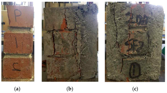
Figure 6.
Damage state after termination of compression tests: (a) C-P; (b) C-SF-30S; (c) C-SF-30B.
3.2. Test for Diagonal Tension Strength
The stress–strain curves from the tests for the diagonal tension strength are plotted in Figure 7. The diagonal tension strength and shear modulus based on the stress–strain curves are summarized in Table 5. All the stresses in the strengthened specimen were calculated based on the cross-sectional area of the bare masonry prism, similar to the compressive strength tests. The average diagonal tension strength and shear modulus for the bare prisms were 0.29 and 1410 MPa, respectively. Strengthening with the ASFRM overlay on one side improved the diagonal tension strength of D-SF-20S and D-SF-30S to 2.34 and 2.47 MPa, respectively; however, the thickness of the overlay did not have a significant effect, as observed in the two specimens. Strengthening using the same material on both sides of the specimen resulted in a diagonal tension strength that was two times higher than that achieved by strengthening on one side; moreover, the thickness of the overlay resulted in a significant improvement in the diagonal tension strength, as observed for D-SF-20B and D-SF-30B.
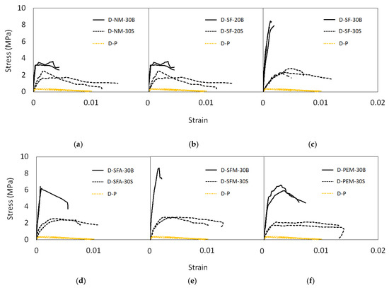
Figure 7.
Diagonal tension stress–shear strain curves: (a) D-NM-30S and D-NM-30B; (b) D-SF-20S and D-SF-20B; (c) D-SF-30S and D-SF-30B; (d) D-SFA-30S and D-SFA-30B; (e) D-SFM-30S and D-SFM-30B; (f) D-PEM-30S and D-PEM-30B.
Table 5.
Diagonal tension strength test results.
Strengthening using the ASFRM, as applied to D-SF-30S and D-SF-30B, resulted in a higher strength compared with strengthening using only a glass fiber mesh-reinforced mortar overlay, as applied to D-NM-30S and D-NM-30B, respectively. The difference in strength increased, particularly when strengthening was performed on both sides. By adding a glass fiber mesh to the ASFRM overlay, the diagonal tension strength increased by 0.23 MPa compared with strengthening on one side in D-SF-30S and D-SFM30S; however, it decreased by 1.59 MPa compared with strengthening on both sides in D-SF-30B and D-SFM30B. Therefore, the glass fiber mesh did not exert a consistent positive effect on the diagonal tension strength. The overall tendency of the improvement in the shear modulus was similar to that in the diagonal tension strength. Specimens D-SFA-30S and D-SFA-30B, whose shear connectors were installed between the ASFRM overlay and masonry, did not yield significant improvements in the diagonal tension strength compared with specimens D-SF-30S and D-SF-30B, which had no shear connectors. Specimens strengthened with the ASFRM achieved higher diagonal tension strengths compared with those strengthened with the PEFRM, particularly for strengthening on one side.
The damage states of the specimens after failure in the diagonal tension strength tests are shown in Figure 8. Prisms without strengthening failed and exhibited cracks along the joints, as shown in Figure 8a. However, the mortar overlay reinforced with only a glass fiber mesh, as in D-NM-30S and D-NM-30B, was damaged, unlike the other strengthened specimens, as shown in Figure 8b. In contrast, cracks were not observed on the ASFRM overlay for D-SF-30S, as shown in Figure 8c, where the masonry layer exhibited a few cracks on the masonry unit and separation between the bed joint and masonry units, as shown in Figure 8d. Instead of a clear diagonal crack on the masonry layer and ASFRM overlay, cracks occurred on the lateral side of the masonry before the maximum load was reached, as shown in Figure 9. Subsequently, additional cracks appeared at the interface between the masonry layer and ASFRM overlay as the load decreased. Based on the observed failure mode, it was assumed that the bond strength between the ASFRM and masonry dominated the diagonal tension failure owing to the high tensile strength of the ASFRM, thereby rendering the diagonal tension strength sensitive to the number of strengthened sides rather than the thickness of the overlay. However, the specimen strengthened on both sides was sensitive to the thickness of the overlay, which is likely due to the direct resistance of the ASFRM overlay.
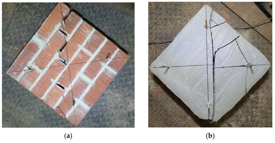
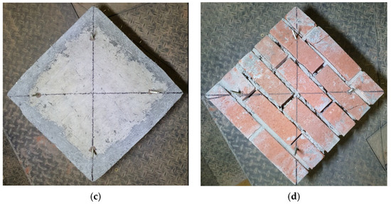
Figure 8.
Damage state observed on front or back side after termination of diagonal tension tests: (a) D-P; (b) D-NM-30B; (c) D-SF-30S (ASFRM overlay); (d) D-SF-30S (masonry layer).
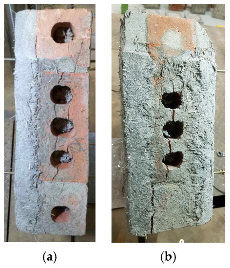
Figure 9.
Damage state observed on lateral side after termination of diagonal tension tests: (a) D-SF-30S; (b) D-SF-30B.
3.3. Test for Bond Strength
The maximum loads from the bond strength tests are summarized in Table 6. The damage state of the specimens after failure is shown in Figure 10. As shown in Figure 10a, the bare prism failed at the bed joints between the masonry units through which the test load was transmitted. Figure 10b shows that the prism strengthened on one side failed at both the bed joints and the overlay-to-masonry interface. Meanwhile, Figure 10c shows that the prism strengthened on both sides failed in the masonry unit at the side with a relatively low strength material, as the load transmitted by the overlay increased and the hole in the inside brick was partially filled during bricklaying. The load transfer and stress at the overlay-to-masonry interfaces are illustrated in Figure 11. The overlay-to-masonry interfaces can be classified into side and middle interfaces. The test load was transmitted from the middle interface to the two side interfaces through the overlay. The area of the interface considered in the calculation of the bond strength was doubled for strengthening on both sides, as shown in Figure 11b. To calculate the bond strength at the overlay-to-masonry interface, the load transmitted through the bed joints directly was subtracted from the total load resisted by the strengthened specimen as follows:
where , , and denote the total load (kN), load shared by the overlay-to-masonry interface (kN), and load shared by the bed joint (kN), respectively. The bond strength at the overlay-to-masonry interface was calculated considering the number of interfaces, as follows:
where and denote the bond strength (MPa) at the overlay-to-masonry interface for strengthening on a single side and on both sides, respectively. denotes the interface area (mm2) between the adjacent masonry units.
Table 6.
Bond strength test results for masonry prisms.
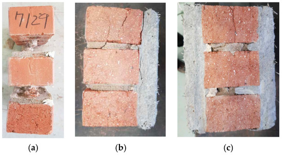
Figure 10.
Damage state after termination of bond strength tests: (a) B-P; (b) SF-30S; (c) SF-30B.
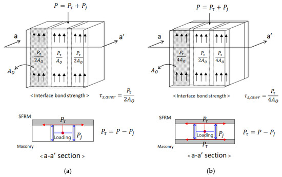
Figure 11.
Transfer of test load through mortar joints and interface between masonry layer and ASFRM overlay: (a) Strengthening on one side; (b) strengthening on both sides.
The bond strengths of the overlay-to-masonry interface calculated using Equations (1)–(3) are summarized in Table 7. The bond strengths for strengthening on one side and both sides were 0.716 and 0.884 MPa, respectively. The lower bond strength by strengthening on one side is attributable to the normal stress exerted on the interface due to the eccentricity between the interface and the line of action for loading. In addition, bond strength tests were conducted for concrete masonry strengthened with the same ASFRM overlay in another study [22], the results of which are presented in Table 7 and used to predict the diagonal tension strength in the following section.
Table 7.
Bond strengths for overlay-to-masonry interface.
4. Design Equations for Strengthening with ASFRM Overlay
Design equations for strengthening with the ASFRM overlay are proposed herein to predict the compressive and diagonal tension strengths based on the test results. The equations are based on the test results for the hollow red clay brick masonry described herein as well as additional test results for concrete brick masonry presented by Yu (2021) [22], who used the same test and analysis methodology as that used in this study. The number of strengthened sides is considered an important variable in the derivation of the design equations based on test observations. The lower-bound strength as well as the expected strength for a retrofit design in accordance with ASCE 41-17 [27] are proposed considering the mean and standard deviation of the test result, as follows:
where is the nominal strength predicted using the proposed design equation; and are the mean and standard deviation of the test strength-over-nominal strength ratio for individual specimens, respectively.
4.1. Design Equations for Compressive Strength
4.1.1. Strengthening on One Side
The compressive strength for prims strengthened on one side was calculated based on the stress distribution assumed in the unsymmetrical cross-section composed of the masonry layer and single-sided ASFRM overlay. This is because most of the damage was concentrated on the masonry layer rather than on the ASFRM overlay, as shown in Figure 6, since the unsymmetrical cross-section was formed by strengthening on one side only. The peak resistance of a strengthened prism in compression is expressed by the sum of the contributions from the masonry layer and ASFRM overlays, as follows:
where , , and denote the total resistance, resistance of the masonry layer, and resistance of the ASFRM overlay, respectively. Similar to Equation (6), can be expressed by , which is the fraction of the resistance by the masonry layer over the total resistance, expressed as follows:
To calculate , the stress distribution was determined for the transformed cross-section illustrated in Figure 12 based on the elastic modulus ratio between the ASFRM overlay and masonry, which is expressed as follows:
where denotes the elastic modulus ratio; is the elastic modulus from the test of bare prisms, i.e., 1780 MPa for the hollow red clay brick masonry, and 4570 MPa for the concrete brick according to Yu et al. [22]; is the elastic modulus for ASFRM (9260 MPa), as listed in Table 3.
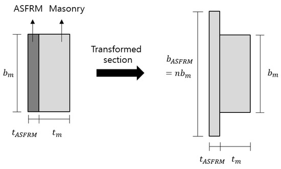
Figure 12.
Transformed section of prisms strengthened on one side.
The distribution of normal stress in the cross section for a prism strengthened on one side in compression was determined by the compressive force and bending moment caused by the eccentric test loading with respect to the centroid of the transformed section, as illustrated in Figure 13. The parabolic stress distribution in Figure 13 was approximated using an equivalent rectangular stress block, where the compressive stress was , which is in accordance with TMS 402 [28]. The equivalent stress block depth denoted by can be determined based on the following moment equilibrium equation between the two areas denoted by and located on the left and right sides of the loading axis, respectively, as shown in Figure 14:
where and represent the distances from the loading axis to the centroids of and , respectively. The value of can be obtained by solving Equation (9) after substituting expressions in for and based on Figure 14. The compressive resistance shared by the masonry layer and ASFRM overlay can be calculated using Equations (10) and (11), respectively, when is larger than the masonry layer thickness but smaller than the total thickness including the ASFRM overlay.
where is the cross-sectional area of the masonry layer, and is the width of the ASFRM overlay transformed into the masonry material. Therefore, the compressive strength of a masonry prism strengthened on one side with the ASFRM overlay can be expressed as follows by incorporating Equations (7), (10) and (11) and the cross-sectional area prior to strengthening:
where and are the compressive strengths of the strengthened masonry prism and bare masonry prism, respectively.
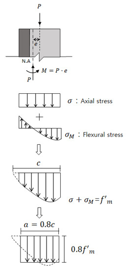
Figure 13.
Stress distribution for strengthening on one side for compressive strength test.
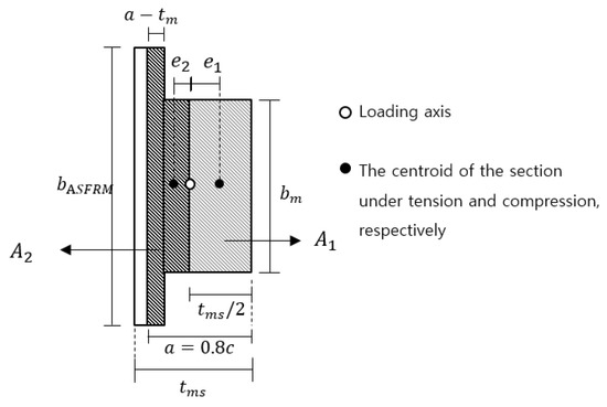
Figure 14.
Detailed transformed section for calculating equivalent stress block.
The compressive strengths predicted using Equation (12) and the corresponding test strengths were compared, as shown in Figure 15, in which the trend lines for both the expected and lower-bound strengths based on Equations (4) and (5) are plotted, respectively. The test strengths for the strengthened masonry prisms in red clay bricks and concrete bricks were 0.89 and 1.17 times the corresponding nominal predicted strength, respectively. In other words, Equation (12) overestimates the compressive strength after strengthening for the red clay brick masonry by approximately 10%; therefore, the value obtained needs to be reduced by a factor of 0.89 before more test data are acquired. For strengthening on both sides, the expected and lower-bound compressive strengths with respect to the nominal strength are summarized in Table 8 and Table 9.
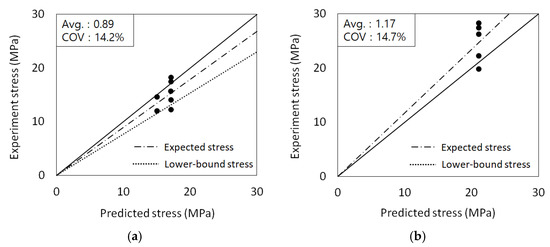
Figure 15.
Predicted and test compressive strengths for prisms strengthened on one side: (a) Red clay brick masonry; (b) concrete brick masonry.
Table 8.
Nominal strength and modification factors for red clay brick masonry.
Table 9.
Nominal strength and modification factors for concrete brick masonry.
4.1.2. Strengthening on Both Sides
The compressive strength of masonry prisms strengthened on both sides can be calculated based on Equation (6) and experimental observations. In tests for the compressive strength, masonry prisms strengthened on both sides experienced compressive failure in the masonry layer and cracks at the masonry-to-overlay interface in the strength degradation region beginning at the strength cap in the load–displacement curves. Cracks or other damages were not observed on the ASFRM overlay. Based on the experimental observations, it was assumed that the full compressive strength of the ASFRM overlay was not developed, and that only a fraction of the strength corresponding to the ultimate strain of the masonry layer contributed to the total compressive strength. Therefore, the total compressive strength is expressed as follows, assuming that the ASFRM remains elastic:
where is the elastic modulus of the ASFRM (as summarized in Table 3); is the ultimate strain of the masonry layer, for which 0.0035 and 0.0025 were applied to the red clay bricks and concrete bricks, respectively, in accordance with TMS 402 [28].
The compressive strengths predicted using Equation (13) and the corresponding test strengths were compared, as shown in Figure 16, in which the trend lines for both the expected and lower-bound strengths based on Equations (4) and (5) are shown. The ratios of the test strength over the nominal strength were 0.83 and 1.04 for the strengthened masonry prisms in red clay bricks and concrete bricks, respectively. In other words, Equation (13) overestimates the compressive strength by approximately 17% after the red clay brick masonry was strengthened; therefore, it needs to be reduced by a factor of 0.83 before more test data are acquired. The overestimation is attributable to the assumption of elastic behavior in the ASFRM masonry. Nonetheless, the accuracy of the predicted compressive strength is expected to be improved by determining the elastic modulus corresponding to in a more sophisticated manner, e.g., using the secant modulus at the critical strain. For strengthening on both sides, the expected and lower-bound compressive strengths with respect to the nominal strength are summarized in Table 8 and Table 9.
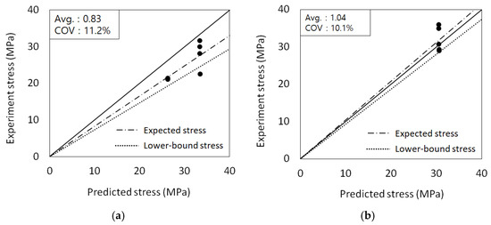
Figure 16.
Predicted and test compressive strengths for prisms strengthened on both sides: (a) Red clay brick masonry; (b) concrete brick masonry.
4.2. Design Equations for Diagonal Tension Strength
In most masonry prisms strengthened with an ASFRM overlay for diagonal tension tests, cracks were developed only in the masonry layer, as shown in Figure 8c,d. This failure occurs because of the principal tensile stress in the diagonal direction, and the corresponding strength can be determined as the sum of the diagonal tension strength of the masonry layer and the sum of bond stress along a strip of unit width in the main diagonal of the interface between the masonry layer and ASFRM overlay, as illustrated in Figure 17, assuming that the horizontal shear stress in the masonry prism is negligible. Therefore, an equation for the diagonal tension strength comprising the two components is proposed as follows: First, the bond stress is assumed to exhibit a parabolic distribution, in which the stresses increase from zero at the corner to the peak at the center of the specimen. The peak bond stress is assumed to be 1.5 times the average bond stress. Therefore, the diagonal tension strength for a strengthened masonry prism is defined as the sum of the diagonal tension strength of the bare masonry prism and the average interface bond stress exerted in the area of unit width, in accordance with Figure 17, as follows:
where is the expected diagonal tension strength for the masonry prism strengthened with an ASFRM overlay; is the diagonal tension strength for a bare masonry prism obtained from tests; and are the width and thickness of the bare masonry prism, respectively, as illustrated in Figure 17. In addition, equals 1 or 2 for strengthening on one side or both sides, respectively. Finally, is the average bond strength, which can be expressed as for the parabolic stress distribution, and can be obtained from the test, as summarized in Table 7.
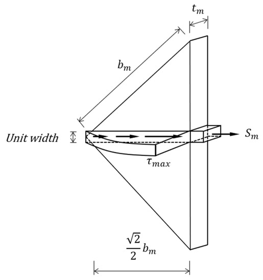
Figure 17.
Distribution of stress contributing to diagonal tension strength for strengthened prisms.
The diagonal tension strengths predicted using Equation (14) and the corresponding test strengths were compared, as shown in Figure 18, in which specimens strengthened with a 30-mm-thick ASFRM overlay on one side and both sides were included, and specimens with anchors for shear connectors were excluded. The trend lines for both the expected and lower-bound strengths based on Equations (4) and (5) are shown in Figure 18. The average ratios of the test strength over the nominal strength were 1.15 and 1.12 for the strengthened masonry prisms in red clay bricks and concrete bricks, respectively. Hence, Equation (14) underestimates the diagonal strength conservatively. The effect of filling the vertical joint partially when plastering the ASFRM might have contributed to the underestimation of the diagonal tension strength; this is because in Equation (14) is based on the strength obtained from specimens with weak vertical mortar joints. The expected and lower-bound diagonal tension strengths are summarized in Table 8 and Table 9, respectively.
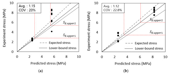
Figure 18.
Predicted and test diagonal tension strengths: (a) Red clay brick masonry; (b) concrete brick masonry.
Equation (14) assumes that the ASFRM overlay does not fail after the peak load is reached. However, diagonal cracks were formed on the ASFRM overlay at the peak load in the case of concrete brick masonry strengthened on both sides. Therefore, the diagonal tension strength calculated using Equation (14) must be limited by an upper bound.
Assuming that the masonry layer and the ASFRM overlay fail simultaneously, the upper bound of the diagonal tension strength can be defined as the sum of the diagonal tension strengths of both elements, as follows:
where is the upper bound to the diagonal tension strength; is the diagonal tension strength of the ASFRM; and are the cross-sectional areas of the masonry layer and ASFRM overlay, respectively. The upper bound strengths are represented by vertical and horizontal broken lines in Figure 18, where and correspond to the specimens strengthened on one side and both sides, respectively. The tensile strength of the ASFRM provided in Table 3 was used instead of to calculate and because of insufficient actual test data. Most of the calculated and tested strengths for the specimens strengthened on both sides were higher than in both Figure 18a,b. In particular, the difference was more significant for the concrete brick masonry. As mentioned above, the unintentional filling of the vertical joint via the ASFRM during the construction of specimens might enhance the actual bare prism strength (as expressed in Equations (14) and (15)). In addition, the accuracy of Equation (14) would have been improved if actual tests for were performed.
4.3. Applicability to Seismic Retrofit Design
The proposed design equations are intended to be applied to the retrofit design of unreinforced masonry walls directly. This is because the toe-crushing, diagonal tension, and bed-joint sliding strengths for unreinforced masonry walls are calculated using the compressive and diagonal tension strengths provided in ASCE 41-17 [27]. However, in the toe-crushing failure, compressive failure is concentrated only in the localized area, unlike the compression failure of masonry prisms in this study. Figure 17 and Equation (14) for diagonal tension failure assume square masonry prisms; therefore, the distribution of bond stress must be redefined for the rectangular shape of masonry prisms. In the case of masonry walls dominated by bed-joint sliding failure, whether such a failure mode can develop in an unreinforced masonry shear wall strengthened with an ASFRM as well as the quantification of the strengthening effect are yet to be elucidated. Therefore, additional studies based on experiments or numerical analyses are necessitated to apply the proposed design equations to actual unreinforced masonry walls with various aspect ratios.
5. Conclusions
A technique for strengthening masonry walls by plastering an ASFRM was investigated by performing compressive and diagonal tension tests for masonry prisms created using hollow red clay bricks and by reproducing poor workmanship. Various test variables associated with the composition of the overlay and interface were considered in the test program. The equations for the nominal compressive and diagonal tension strengths and the empirical modification factors to obtain the expected and lower-bound strengths were proposed and verified using test data. The results of this study can be summarized as follows:
Strengthening poorly constructed masonry prisms using the ASFRM overlay was effective for both the compression and diagonal tension, but more efficient for the latter. The compressive and diagonal tension strengths increased by 150% and 2660%, respectively, by plastering the ASFRM on 0.5B red clay brick masonry. In terms of the design variables for retrofit, the thickness of the ASFRM overlay had a negligible effect on both the compressive and diagonal tension strengths in the tests, whereas strengthening on both sides was much more effective than strengthening on one side. Similarly, using the glass fiber mesh and shear connectors did not yield significant enhancements in terms of strength compared with plastering only the ASFRM with the same thickness.
Owing to the relatively high strength of the ASFRM overlay, the specimen failed in the masonry layer first, and then cracks were formed at the interface between the masonry and overlay. Therefore, the elastic modulus ratio affecting the load share between the two layers and the bond strength between the masonry and overlay are vital to strength prediction. Consequently, the proposed strength equations predicted the test results with considerable accuracy. However, additional experiments or numerical analyses are necessary to verify the assumptions underlying the proposed design equations with an extended range of test variables, as well as to utilize these equations in the retrofit design of actual unreinforced masonry walls with various aspect ratios or subjected to stress concentration.
Author Contributions
Conceptualization, J.-H.P.; software, J.-H.Y.; formal analysis, J.-H.Y.; investigation, J.-H.Y.; writing—original draft preparation, J.-H.Y.; writing—review and editing, J.-H.P.; supervision, J.-H.P. All authors have read and agreed to the published version of the manuscript.
Funding
This work was supported by the Korea Agency for Infrastructure Technology Advancement (KAIA) grant funded by the Ministry of Land, Infrastructure, and Transport (Grant 21CTAP-C152105-03).
Institutional Review Board Statement
Not applicable.
Informed Consent Statement
Not applicable.
Data Availability Statement
Not applicable.
Conflicts of Interest
The authors declare no conflict of interest.
Notation
| Cross-sectional area for the ASFRM overlay | |
| Cross-sectional area of the masonry layer in a strengthened prism | |
| Interface area between the adjacent masonry units | |
| Area located on the left-hand side of the loading axis in a masonry prism under compression | |
| Area located on the right-hand side of the loading axis in a masonry prism under compression | |
| Equivalent stress block depth | |
| Width of the masonry layer | |
| Elastic modulus of ASFRM | |
| Elastic modulus of a bare prism | |
| Distance from the loading axis to the centroids of | |
| Distance from the loading axis to the centroids of | |
| Elastic modulus ratio | |
| Number of strengthened sides on the masonry prism | |
| Total load in the compression test | |
| Compressive resistance by the ASFRM overlay in the strengthened prism | |
| Load shared by the overlay-to-masonry interface | |
| Compressive resistance by the masonry layer in the strengthened prism | |
| Total compressive resistance of the strengthened masonry prism | |
| Load shared by the overlay-to-masonry interface | |
| Expected strength | |
| Nominal strength predicted by the proposed design equation | |
| Lower bound strength | |
| Diagonal tension strength of the ASFRM | |
| Expected diagonal tension strength for the strengthened masonry prism | |
| Upper bound to the diagonal tension strength | |
| Upper bound to the diagonal tension strength for the specimen strengthened on a single side | |
| Upper bound to the diagonal tension strength for the specimen strengthened on both sides | |
| Diagonal tension strength for the bare masonry prism obtained from tests | |
| Standard deviation of the test strength-over-nominal strength ratio for individual specimen | |
| Thickness of the masonry layer | |
| Thickness of the strengthened masonry prism | |
| Standard deviation of the test strength-over-nominal strength ratio for individual specimen | |
| Fraction of the compressive resistance by the masonry layer over the total resistance | |
| Ultimate strain of the masonry layer | |
| Normal stress in the section of the masonry prism | |
| Compressive strength for the strengthened masonry prism | |
| Flexural stress in a section of the masonry prism | |
| Compressive strength for the bare masonry prism | |
| Average bond strength between the ASFRM and masonry layer | |
| Bond strength at the overlay-to-masonry interface for strengthening on both sides | |
| Bond strength at the overlay-to-masonry interface for strengthening on a single side | |
| Peak bond stress |
References
- FEMA P-774. Unreinforced Masonry Buildings and Earthquakes; FEMA: Washington, DC, USA, 2009.
- Doğangün, A.; Ural, A.; Livaoğlu, R. Seismic performance of masonry buildings during recent earthqukes in Turkey. In Proceedings of the 14th World Conference on Earthquake Engineering (14WCEE), Beijing, China, 12–17 October 2008; pp. 1–8. [Google Scholar]
- D’Altri, A.M.; Sarhosis, V.; Milani, G.; Rots, J.; Cattari, S.; Lagomarsino, S.; Sacco, E.; Tralli, A.; Castellazzi, G.; Miranda, S. Modeling strategies for the computational analysis of unreinforced masonry structures: Review and classification. Arch. Comput. Methods Eng. 2020, 27, 1153–1185. [Google Scholar] [CrossRef]
- Korumaz, M.; Betti, M.; Conti, A.; Tucci, G.; Bartoli, G.; Bonora, V.; Korumaz, A.G.; Fiorini, L. An integrated Terrestrial Laser Scanner (TLS), Deviation Analysis (DA) and Finite Element (FE) approach for health assessment of historical structures. A minaret case study. Eng. Struct. 2017, 153, 224–238. [Google Scholar] [CrossRef]
- Funari, M.F.; Spadea, S.; Lonetti, P.; Fabbrocino, F.; Luciano, R. Visual programming for structural assessment of out-of-plane mechanisms in historic masonry structures. J. Build. Eng. 2020, 31, 101425. [Google Scholar] [CrossRef]
- Yang, K.H.; Mun, J.H.; Hwang, S.H. Cyclic shear behavior of masonry walls strengthened with prestressed steel bars and glass fiber grids. Compos. Struct. 2020, 238, 1–12. [Google Scholar] [CrossRef]
- Ismail, N.; Petersen, R.B.; Masia, M.J.; Ingham, J.M. Diagonal shear behavior of unreinforced masonry wallettes strengthened using twisted steel bars. Constr. Build. Mater. 2011, 25, 4386–4393. [Google Scholar] [CrossRef]
- Silva, B.; Benetta, M.D.; da Porto, F.; Modena, C. Experimental assessment of in-plane behaviour of three-leaf stone masonry walls. Constr. Build. Mater. 2014, 53, 149–161. [Google Scholar] [CrossRef]
- Taghdi, M.; Bruneau, M.; Saatcioglu, M. Seismic retrofitting of low-rise masonry and concrete walls using steel strips. ASCE J. Struct. Eng. 2000, 126, 1017–1025. [Google Scholar] [CrossRef]
- Darbhanzi, A.; Marefat, M.S.; Khanmohammadi, M. Investigation of in-plane seismic retrofit of unreinforced masonry walls by means of vertical steel ties. Constr. Build. Mater. 2014, 52, 122–129. [Google Scholar] [CrossRef]
- Ghiassi, B.; Marcari, G.; Oliveira, D.V.; Lourenço, P.B. Numerical analysis of bond behavior between masonry bricks and composite materials. Eng. Struct. 2012, 43, 210–220. [Google Scholar] [CrossRef]
- Bae, B.I.; Yun, H.J.; Choi, C.S.; Choi, H.K. Evaluation of shear strength of unreinforced masonry walls retrofitted by fiber reinforced polymer sheet. J. Korea Concr. Inst. 2012, 24, 305–313. [Google Scholar] [CrossRef][Green Version]
- Choi, H.K.; Bae, B.I.; Choi, C.S. Lateral resistance of unreinforced masonry walls strengthened with engineering cementitious composite. Int. J. Civil. Eng. Korea 2016, 14, 411–424. [Google Scholar] [CrossRef]
- D’Ambrisi, A.; Mezzi, M.; Caporale, A. Experimental investigation on polymeric net-RCM reinforced masonry panels. Compos. Struct. 2013, 105, 207–215. [Google Scholar] [CrossRef]
- Almeida, J.A.P.P.; Pereira, E.N.B.; Barros, J.A.O. Assessment of overlay masonry strengthening system under in-plane monotonic and cyclic loading using the diagonal tensile test. Constr. Build. Mater. 2015, 94, 851–865. [Google Scholar] [CrossRef]
- Mustafaraj, E.; Yardim, Y. In-plane shear strengthening of unreinforced masonry walls using GFRP jacketing. Period. Polytech. Civ. Eng. 2018, 62, 330–336. [Google Scholar] [CrossRef]
- Benedetti, A. In plane behaviour of masonry walls reinforced with mortar coatings and fibre meshes. Int. J. Archit. Herit. 2019, 13, 1029–1041. [Google Scholar] [CrossRef]
- Kreivakais, T. Experimental study on carbon fiber textile reinforced mortar system as a means for confinement of masonry columns. Constr. Build. Mater. 2019, 208, 723–733. [Google Scholar] [CrossRef]
- Ombres, L.; Verre, S. Analysis of the Behavior of FRCM Confined Clay Brick Masonry Columns. Fibers 2020, 8, 11. [Google Scholar] [CrossRef]
- Yu, J.-H.; Park, J.-H. Investigation of Steel Fiber-Reinforced Mortar Overlay for Strengthening Masonry Walls by Prism Tests. Appl. Sci. 2020, 10, 6395. [Google Scholar] [CrossRef]
- Yu, J.H.; Myeong, S.J.; Park, J.H. Enhancement of compressive and shear strength for concrete masonry prisms with steel fiber-reinforced mortar overlay. J. Earthq. Eng. Soc. Korea 2021, 25, 21–32. [Google Scholar] [CrossRef]
- Yu, J.H. Retrofit Effects of Steel Fiber-Reinforced Mortar Plastered on Unreinforced Masonry Walls. Master’s Degree, Incheon National University, Incheon, Korean, 2021. [Google Scholar]
- ASTM C1314. Standard Test Method for Compressive Strength of Masonry Prisms; ASTM International: West Conshohocken, PA, USA, 2014. [Google Scholar]
- ASTM E519/E519M. Standard Test Method for Diagonal Tension (Shear) in Masonry Assemblages; ASTM International: West Conshohocken, PA, USA, 2015. [Google Scholar]
- Lee, S.K.; Ju, Y.K.; Lee, S.S.; Song, H.Y. A study on the dynamic and durability properties of high-ductile mortar using reinforced fiber. J. Reg. Assoc. Archit. Inst. Korea 2008, 1, 931–936. [Google Scholar]
- Korea Construction Standards 41 16 01. Plaster Work; Ministry of Land, Infrastructure and Transport: Seoul, Korea, 2018.
- ASCE 41-17. Seismic Evaluation and Retrofit of Existing Buildings; ASCE: Reston, VA, USA, 2017. [Google Scholar]
- TMS 402. Building Code Requirements for Masonry Structures; The Masonry Society: Longmont, CO, USA, 2012. [Google Scholar]


Publisher’s Note: MDPI stays neutral with regard to jurisdictional claims in published maps and institutional affiliations. |
© 2021 by the authors. Licensee MDPI, Basel, Switzerland. This article is an open access article distributed under the terms and conditions of the Creative Commons Attribution (CC BY) license (https://creativecommons.org/licenses/by/4.0/).