Article

A Linkage Representation of the Human Hand Skeletal System Using CT Hand Scan Images

1
School of Artificial Intelligence and Computer Science, Jiangnan University, Wuxi 214122, China
2
Department of Industrial and Management Engineering, Pohang University of Science and Technology, Pohang 37673, Korea
3
Department of Rehabilitation Medicine, Pohang Stroke and Spine Hospital, Pohang 37659, Korea
*
Author to whom correspondence should be addressed.
Appl. Sci. 2021, 11(13), 5857; https://doi.org/10.3390/app11135857
Submission received: 30 May 2021 / Revised: 17 June 2021 / Accepted: 22 June 2021 / Published: 24 June 2021
(This article belongs to the Special Issue Novel Approaches and Applications in Ergonomic Design)

Abstract

:
The present study proposed a method for establishing a linkage representation of the human hand skeletal system. Hand skeletons of 15 male subjects were reconstructed from computed tomography (CT) scans in 10 different postures selected from a natural hand-closing motion. The wrist joint center was estimated as the intersection of the centerline of the metacarpal of the middle finger and the distal wrist crease. The remaining joint centers were kinematically estimated based on the relative motion between the distal bone segment and the proximal bone segment of a given joint. A hand linkage representation was then formed by connecting the derived joint centers. Regression models for predicting internal hand link lengths using hand length as the independent variable were established. In addition, regression models for predicting the joint center coordinates of the thumb carpometacarpal (CMC) and finger metacarpophalangeal (MCP) joints using hand length or hand breadth were established. Our models showed higher R2 values and lower maximum standard errors than the existing models. The findings of the present study can be applied to hand models for ergonomic design and biomechanical modeling.

1. Introduction

A linkage representation of the human hand skeletal system is widely used in biomechanical modeling and ergonomic design to define hand segments and link lengths. A hand linkage structure can be established based on a given set of hand segment length data. However, an inappropriate linkage is commonly constructed based on bone length data or bony landmark locations [1].
Although the human skeletal system is not a perfectly rigid linkage system, a rigid linkage system is commonly established. The optimal linkage representation should satisfy (1) the closest approximation of the centers of the relative rotations between two adjacent body segments by the joint centers or centers of rotation (CoRs) in the linkage representation and (2) the minimal variation of the link lengths (distances between two adjacent joints) over a certain time period or range of motion [1]. The use of a rigid linkage system can benefit both biomechanical modeling and anthropometric studies by avoiding problems such as an end-point offset in forward kinematics [2], a failure in inverse dynamics [3], and the disparity between static and dynamic anthropometric data [1].
Human body link lengths are measured in a static posture based on anatomical bony landmarks. The landmarks are either anatomically palpable or identified from imaging [4,5,6]. However, joint centers and corresponding anatomical bony landmarks are different from each other, which define link lengths and bone lengths, respectively [7]. Buchholz et al. [8] measured link lengths and bone lengths with six fresh cadaver hands using radiographic techniques. They anatomically estimated joint centers as the center of curvature of the head of the bone proximal to the corresponding joint. They also estimated joint centers of proximal interphalangeal (PIP) and distal interphalangeal (DIP) joints using Reuleaux’s method [9] and found small differences (<1.4 mm) from those of the anatomical estimation. Regression formulas for predicting joint centers from bone lengths and those for predicting link lengths from hand lengths were established in their study. Buchholz et al.’s study has several limitations as follows. First, joint centers were estimated anatomically rather than kinematically. Though they compared their anatomically estimated joint centers of PIP and DIP joints to those estimated by Reuleaux’s method and found small differences between the two results, they did not compare the estimation methods for the carpometacarpal (CMC) and metacarpophalangeal (MCP) joints. Furthermore, Reuleaux’s method is considered crude and error prone [1]. Second, they used cadaver hands to estimate joint centers that might not be the same as those estimated in vivo [1]. Third, two-dimensional (2D) radiographic images taken from the sagittal view were used to estimate the joint centers that can be different from those estimated using a three-dimensional (3D) hand skeleton. Fowler et al. [10] reconstructed a 3D hand skeleton from magnetic resonance imaging (MRI) scans and estimated the location of a finger joint CoR as the center of curvature of the portion of the head of the proximal bone segment in contact with the base of the distal bone segment of the finger joint in the sagittal plane. However, their method is still based on anatomy rather than kinematics.
Joint centers or CoRs can be estimated using surface-marker-defined finger motions recorded from a motion capture system. Algorithms for estimating CoRs from surface-marker motion data have been developed [11,12,13,14]. For example, Zhang et al. [14] estimated finger joint CoRs from surface-marker flexion–extension motions by minimizing the time-variance of the internal link lengths based on an empirically quantifiable relationship between the local movement of a surface marker around a joint and the corresponding joint flexion–extension angle. However, the estimated CoRs could be affected by the deformation and movement of the dorsal finger skin where the marker is attached during finger movement.
The objectives of the present study include (1) proposing a novel method for estimating hand joint CoRs from 3D hand skeleton motions reconstructed from computed tomography (CT) scans and building participant-specific linkages from the derived hand joint CoRs and (2) establishing regression formulas to predict locations of CoRs of the thumb CMC joint and the MCP joints of the other four fingers from hand lengths and hand breadths and those to predict internal hand link lengths from hand lengths to build a general linkage from the given hand dimensions.

2. Materials and Methods

2.1. Participants

Fifteen right-handed males (age = 23.7 ± 2.0 years, ranging from 20 to 28) having no history of musculoskeletal injuries participated in the present study. This study included only male subjects by considering the potential harm from radiation exposure to women. The participants were recruited from three size categories classified based on different sizes of hand length (small: ≤181.0 mm for less than the 33rd percentile; medium: 181.0 to 187.0 mm for the 33rd to 66th percentiles; large: >187.0 mm for greater than the 66th percentile; Size Korea, 2010) with five participants in each category. The study was approved by the Institutional Review Board of Pohang Stroke and Spine Hospital (Project identification code: 37100475-201802-HR-001, date of approval: 2 March 2018). Informed consent was obtained from each subject.

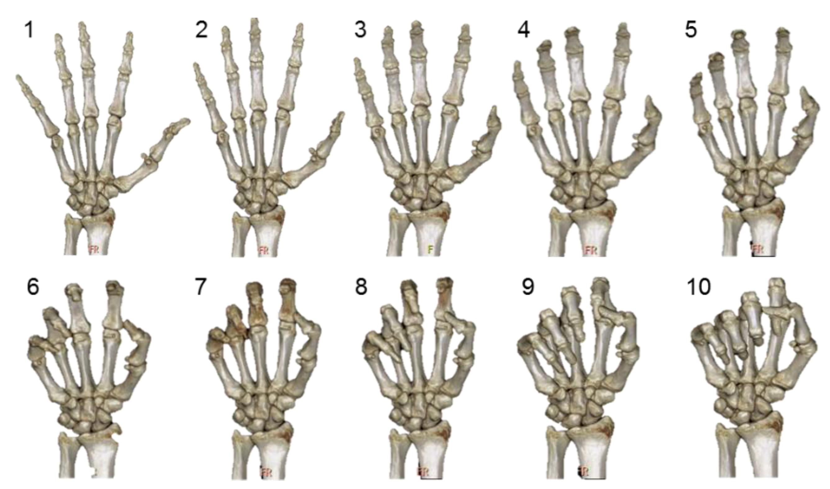
2.2. CT Data Acquisition and Processing

CT data of the right hand of each participant in ten postures were acquired by a radiologist at Pohang Stroke and Spine Hospital. As shown in Figure 1, the ten postures were sequentially selected from a natural hand motion starting from a fully extended posture (Posture 1) and ending at a fist posture (Posture 10) with an approximately 10-degree difference in flexion of the PIP joint of the index finger between two adjacent postures visually estimated by an experimenter. The difference was not objectively measured during the CT scan to guarantee natural motions of the hand. A 256-slice CT scanner (Brilliance iCT; Philips Healthcare, Cleveland, OH, USA) was used to sequentially scan the ten postures while a participant was steadily holding each of the ten postures. The dorsal hand of a participant lay on a device individually fabricated by paper clay for each participant to fix the hand of the participant. The scanning was performed within one minute to capture the ten postures (3 to 5 s per scan) for each participant. The participants were covered by a lead-free radiation shielding apron (FC001; Longkou Sanyi Medical Device Co., Ltd., Longkou, China) and asked to lie face down and stretch out their right arms over their heads to keep the rest of their body away from the CT scanner to protect them from radiation during scanning. Each scan consisted of 576 to 670 CT slices with a resolution of 512 × 512 pixels and a slice thickness of 0.44 mm for a posture depending on the participant’s hand size. More detailed information on the CT data acquisition method can be found in our previous paper [15].
The 3D skin and skeleton of a participant’s hand in each of the ten postures were semiautomatically reconstructed from the corresponding CT data by the Medical Imaging Interaction Toolkit (MITK) [16]. The connected twenty-nine bone segments, including the radius, ulna, eight carpal bones (hamate, pisiform, triquetral, lunate, scaphoid, capitate, trapezium, and trapezoid), five metacarpals, five proximal phalanges, four middle phalanges, and five distal phalanges, in Posture 1 were manually separated by a subtraction function in MITK. Each of the separated bone segments was exported as a file with the polygon (PLY) format by RapidForm 2006 (Inus Technology, Inc., Seoul, Korea). The twenty-nine bone segments in Posture 1 (template posture) were then registered to those in the remaining nine postures so that all the bone segments in the ten postures had the same bone surfaces. First, each bone in Posture 1 was roughly registered to that in a target posture by aligning three points selected at a similar position, each from the template bone surface and the target bone surface. Then, a fine registration was performed to precisely register the template bone to the target bone using the iterative closest point (ICP) algorithm [17]. More detailed information on the registration method can be found in our previous paper [15].

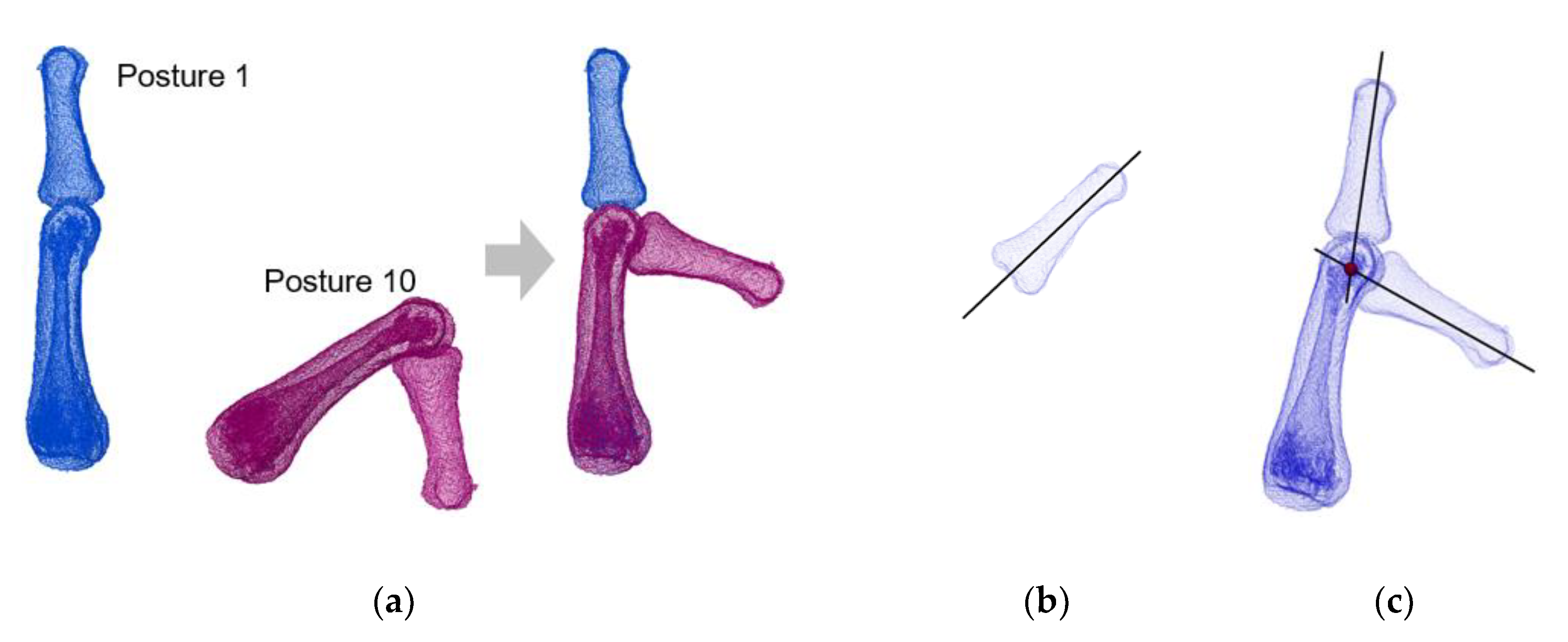
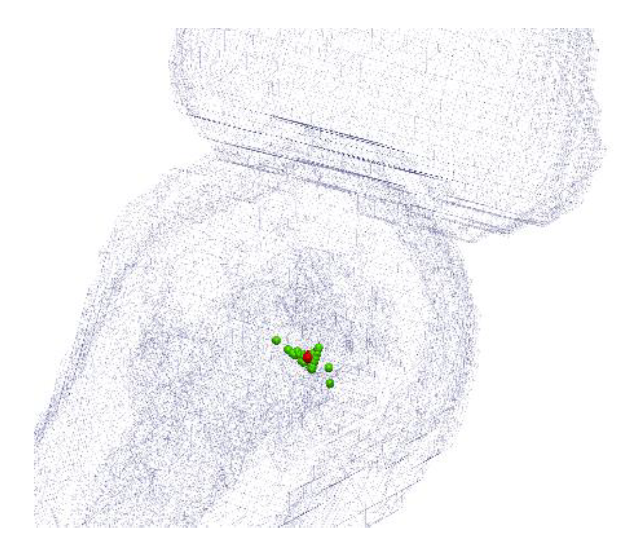
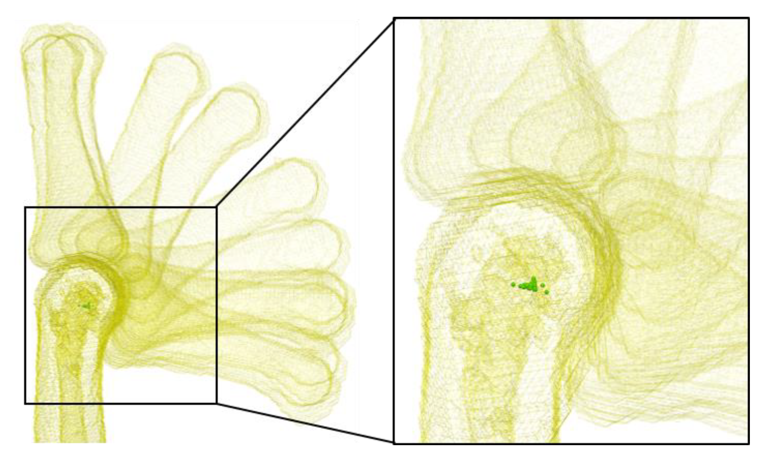
2.3. Joint Centers Estimation

The wrist joint center was estimated as the intersection of the distal wrist crease and the centerline of the third metacarpal [18]. The remaining finger joint centers were estimated by a novel method developed in the present study. The method consists of two steps: (1) estimation of finite joint centers between different hand postures and (2) estimation of joint centers as the centroid of the finite joint centers. Finite joint centers are estimated in three steps: (1) alignment of proximal bone segments of a joint at different postures to measure the relative motions of the distal bone segments of the joint from one posture to another, (2) identification of centerlines of the distal bone segments of the joint at different postures, and (3) determination of finite joint centers as the intersection points of the identified centerlines at different postures, as shown in Figure 2. The alignment of the proximal bone segments of the joint was performed using the abovementioned three-point alignment method in RapidForm 2006. The centerlines of the distal bone segments were identified in two steps: (1) acquisition of a preliminary centerline using the principal component analysis (PCA) method and (2) refinement of the preliminary centerline to obtain the fine centerline by performing a linear fit of the centroids of the surface vertices at the perpendicular planes to the preliminary centerline along the distal bone shaft, the part of a bone excluding the two ends of the bone. More detailed information on the centerline identification method can be found in our previous paper [15]. After all the finite joint centers of a joint were determined, the joint center of that joint was derived as the centroid of the finite joint centers using a k-means clustering method [19], as shown in Figure 3.

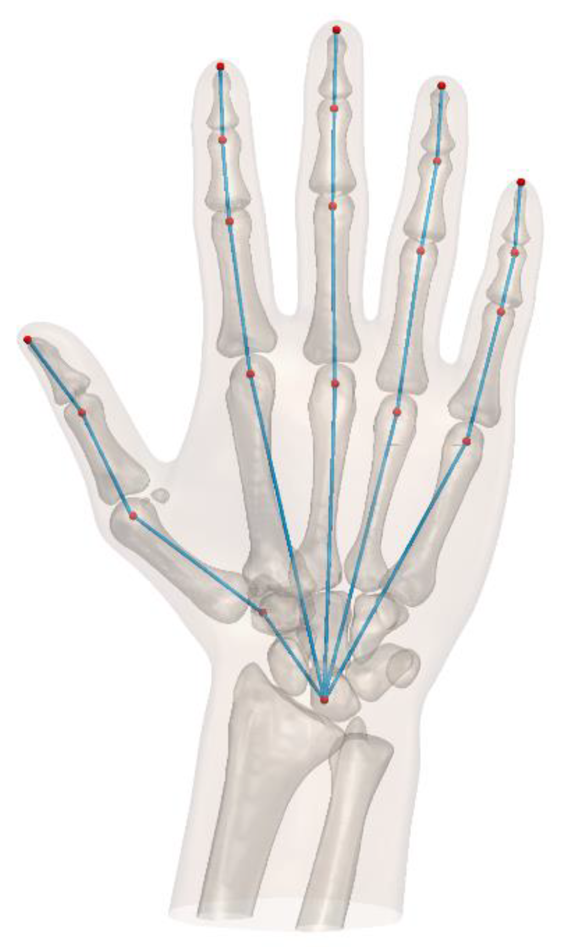
2.4. Linkage System Establishment

The linkage system of the hand for each participant was established by connecting the derived joint centers, as shown in Figure 4. Each finger has four finger segments. For the thumb, Segment 1 is the carpal, Segment 2 the metacarpal, Segment 3 the proximal phalangeal, and Segment 4 the distal phalangeal. For the four fingers, Segment 1 is the carpometacarpal, Segment 2 the proximal phalangeal, Segment 3 the middle phalangeal, and Segment 4 the distal phalangeal. The global coordinate system of the linkage has an origin at the center of the wrist joint, with the y-axis pointing to the center of the MCP joint of the middle finger, the x-axis along the distal wrist crease in the ulnar direction, and the z-axis perpendicular to the xy-plane in the dorsal direction, as shown in Figure 4. In the coordinate system, the centers of MCP joints of the index and middle fingers and the wrist joint are defined to be located in the xy-plane. Thus the z-coordinates of the three joint centers are equal to zero.

2.5. Regression Models Establishment

Internal hand link lengths were calculated as the distances between adjacent joint centers. Regression models for estimating link lengths based on hand length were constructed. Regression models for predicting positions of the MCP joint centers of the index, middle, ring, and little fingers and that of the CMC joint center of the thumb were built. The x-coordinate was modeled as a linear function of hand breadth. The y-coordinate was modeled as a linear function of hand length. The z-coordinate was modeled as a linear function of hand length or hand breadth using stepwise regression. All statistical analyses were conducted using Minitab v. 18 (Minitab, Inc., State College, PA, USA) at a significance level of 0.05.

3. Results

Joint centers of all the participants’ right hands were obtained. Table 1 shows the locations of the estimated joint centers for a participant in the defined global coordinate system. Figure 5 shows the established linkage representation of the participant’s hand by connecting the estimated joint centers. Intra- and interobserver variation of the estimated joint centers was evaluated for a participant. For intraobserver variation, the mean difference ± standard deviation between two measures was 0.4 ± 0.7 mm (ranging from –1.3 to 1.8). For interobserver variation, the mean difference ± standard deviation between two measures was 0.7 ± 2.0 mm (ranging from −1.9 to 4.1).
Link length (LL) was modeled as a function of hand length (HL): LL = A × HL ± error. The coefficients and standard errors for the linear models are shown in Table 2. R2 values ranged from 0.991 to 0.999. Standard errors for these models were found below 1.1 mm.
The x-coordinates of the CMC joint center of the thumb and the MCP joint centers of the other four fingers were modeled as a linear function of hand breadth (HB): x = B × HB ± error. The y-coordinates were modeled as a linear function of hand length: y = C × HL ± error. The z-coordinates were modeled as a linear function of hand breadth or hand length using stepwise regression: z = D × HB/HL ± error. Coefficients for these models are shown in Table 3. R2 values ranged from 0.883 to 0.999. Standard errors for these models were below 1.7 mm.
The proposed regression models were validated with another participant (hand length = 189 mm and hand breadth = 94 mm) besides the 15 participants. As shown in Table 4, the differences between the internal hand link lengths estimated from the proposed regression models and the actural internal hand link lengths ranged from –2.6 to 3.9 mm. As shown in Table 5, the differences between the coordinates of the CMC joint center of the thumb and the MCP joint centers of the other four fingers estimated from the proposed regression models with the actural coordinates ranged from −3.1 to 3.5 mm.

4. Discussion

The present study proposed a novel method for estimating hand joint centers from 3D hand skeleton motions reconstructed from CT scans and building participant-specific linkages from the derived hand joint centers. The novelty of our method lies in (1) the use of 3D hand skeleton motions reconstructed from CT scans, (2) the use of the same bone surfaces for different hand postures by registration of each bone segment from the template posture to that from each of other postures, (3) estimation of finite joint centers among different postures, and (4) determination of joint centers as the centroid of the estimated finite joint centers. The use of 3D hand skeleton motions ensures that joint centers are kinematically estimated. The use of the same bone surfaces for different hand postures makes sure that the same centerlines of the distal bone segments of a given joint at different postures are identified so that an accurate finite joint center can be determined by the intersection point of the centerlines at different postures. A finite joint center estimated between two different postures represents the center of the relative rotation between two adjacent body segments from one posture to the other. The centroid of all the finite joint centers estimated among different postures can most closely approximate the centers of the relative rotations between the two adjacent body segments. Thus the participant-specific linkages built from the derived joint centers can satisfy the optimal criteria stated.
Finite joint centers vary with the change of flexion–extension of the hand, as shown in Figure 6. Mean distance between the finite joint centers of a hand joint in the present study ranged from 0.5 mm to 1.4 mm, indicating that the variation of finite joint centers was quite small during flexion–extension of the hand. Such a small variation might not have a significant effect on the motion of a hand joint during ergonomic analysis.
The proposed method for estimation of the location of a joint center showed high intra- and interobserver precision. The interobserver variation was slightly higher than the intraobserver variation. The high intra- and interobserver precision of the proposed method were because of its high automation level. The slightly higher interobserver variation was mainly caused by the estimation of the wrist joint center. A 2 mm difference was found in the y-coordinate of the estimated wrist joint center between two observers, caused by the difference in identifying the location of distal wrist crease by the two observers.
The present study established regression models to predict internal hand link lengths from hand lengths and the locations of CoRs of the thumb CMC joint and the MCP joints of the other four fingers from hand length and hand breadth. The regression models can be used to effectively build a general linkage by measuring the hand length and the hand breadth of a particular person. Our models have higher R2 values (0.883 to 0.999) than those (0.30 to 0.99) of Buchholz et al.’s models. The maximum standard error of the coefficients of our models is 0.008, whereas that of Buchholz et al.’s models is 0.010. Our models provide longer link lengths for Segment 1 of the five fingers and Segment 4 of the four fingers and shorter link lengths for the remaining finger segments than those of Buchholz et al.’s models, indicating that the CoRs of the interphalangeal (IP) and CMC joints of the thumb and the MCP joints of the four fingers estimated by our method are further away from the wrist joint center than those estimated by Buchholz et al.’s method; the CoRs of the DIP joints of the four fingers estimated by our method are closer to the wrist joint center than those estimated by Buchholz et al.’s method. The differences in the locations of joint centers between our study and Buchholz et al.’s study could be caused by several factors. First, Buchholz et al. [8] anatomically estimated joint centers as the curvature center of the proximal bone head of a given joint, whereas we kinematically estimated joint centers as the centroid of all finite joint centers using 3D hand skeleton motions reconstructed from CT scans. Second, they used cadaver hands to estimate joint centers, whereas we did in vivo. Lastly, Buchholz et al. used 2D radiographic images taken from the sagittal view to estimate joint centers, whereas we used 3D hand skeletons.
The present study built regression models to estimate the z-coordinates of the CMC joint center of the thumb and the MCP joint centers of the ring and little fingers as a linear function of hand breadth or hand length rather than hand thickness. Regression models based on hand thickness (HT; z = E × HT ± error) were constructed but found inferior to those based on hand length or hand breadth. Coefficients of these models (mean ± standard error and R2) were –0.666 ± 0.020 (0.987) for the CMC joint center of the thumb, –0.187 ± 0.018 (0.889) for the MCP joint center of the ring finger, and –0.360 ± 0.035 (0.886) for the MCP joint center of the little finger. These models showed slightly higher R2 values for the ring finger but lower R2 values for the thumb and little finger and much higher standard errors than the models based on hand length or hand breadth. The Pearson correlation analysis showed that the correlation between hand thickness and hand length or hand breadth was weak and not statistically significant. The Pearson correlation coefficients were 0.337 (p = 0.220) for hand thickness and hand length, 0.368 (p = 0.177) for hand thickness and hand breadth, and 0.703 (p = 0.003) for hand length and hand breadth. The weak correlation between hand thickness and hand length or hand breadth could be caused by the obesity level of a participant’s hand. For example, a relatively small hand could have a relatively large hand thickness if the obesity level of the participant’s hand is relatively high, and vice versa. Thus, hand thickness is not preferred for estimating the z-coordinates of the CMC joint center of the thumb and the MCP joint centers of the ring and little fingers.
The major concern of the present study is the use of a CT scan. Magnetic resonance imaging (MRI) that has no ionizing radiation is an alternative to a CT scan. However, we chose a CT scan instead of an MRI scan in our study after carefully considering several aspects. First, we need to sequentially capture ten hand postures in a short period of time to make sure natural hand motions are captured. A CT scan takes less than one minute (3 to 5 s per scan) to capture the ten postures, whereas an MRI scan takes five hours (30 min per scan), which is practically infeasible. Second, a CT scan performs better in bony structure imaging than an MRI scan that is more suitable for soft tissue imaging. Lastly, the total exposure to radiation of a CT scan could be 5 to 40 mSv (0.5 to 4.0 mSv per scan × 10 trials), which is lower than the dose limit of 500 mSv for the hand in a year recommended by Ionizing Radiation Regulations [20].
The present study could benefit anthropological analyses, especially paleoanthropological ones focusing on evolutionary hand biomechanics. The proposed method can be used to build biomechanical models, especially for fossil hominins to study the grasping efficiency of ancient humans to highlight the importance of cultural processes and manual dexterity in later human evolution [21,22]. Karakostis et al. [22] proposed a step-by-step method for assessing the location of the CMC joint center of the thumb. Their study showed significant intra- and interobserver precision based on a double-blind procedure.
The present study estimated the wrist joint center anatomically rather than kinematically. The reason that we did not use our proposed method to estimate the wrist joint center was due to the excessive exposure to the ionizing radiation by extra CT scans of the wrist motions. As a future study, the wrist joint center needs to be estimated by studying the wrist motions with MRI scans. The regression models were constructed based on Asian hands in the present study. To find out whether the regression models in this study are applicable for Caucasians, a further study including Caucasian participants is needed. The present study relied on 10 postures from a fist closing motion. For future study, diverse grasping postures need to be included to test whether the proposed method is applicable to model other grasping postures or not. The findings of the present study can be applied to establishing hand models for the ergonomic design of handheld products and biomechanical modeling of the human hand.

5. Conclusions

A novel method was developed to estimate hand joint centers from 3D hand skeleton motions measured from CT scans. Participant-specific linkages were then constructed from the derived hand joint centers. Finite joint centers of a given joint among different postures were estimated based on the proposed method. Then, the joint center of the given joint was determined as the centroid of the estimated finite joint centers. The estimated joint centers were connected to form a linkage for each participant. Furthermore, the present study built regression models to predict internal hand link lengths from hand length and the locations of CoRs of the thumb CMC joint and the MCP joints of the other four fingers from hand length and hand breadth to effectively build a general linkage by simply measuring hand length and hand breadth of a particular person. Our regression models were found superior to Buchholz et al.’s models in terms of R2 and maximum standard error.

Author Contributions

Conceptualization, X.Y.; methodology: X.Y.; validation: X.Y. and H.Y.; formal analysis: Y.C., Z.L. and X.Y.; investigation: X.Y. and H.Y.; resources: X.Y., D.P. and H.Y.; data curation: X.Y., H.J. and H.Y.; writing—original draft preparation: Y.C. and X.Y.; writing—review and editing: Y.C., X.Y., H.J., D.P. and H.Y.; visualization: Y.C., Z.L. and X.Y.; supervision: X.Y.; project administration: X.Y. and H.J. and H.Y.; funding acquisition: X.Y. and H.Y. All authors have read and agreed to the published version of the manuscript.

Funding

This research was jointly funded by the Fundamental Research Funds for the Central Universities (JUSRP12051) and the National Research Foundation of Korea (NRF) funded by the Ministry of Education, Science and Technology (NRF-2020M3C1B6113677; NRF-2018K1A3A1A20026539).

Institutional Review Board Statement

The study was conducted according to the guidelines of the Declaration of Helsinki and approved by the Institutional Review Board of Pohang Stroke and Spine Hospital (37100475-201802-HR-001).

Informed Consent Statement

Informed consent was obtained from all subjects involved in the study.

Conflicts of Interest

The authors declare no conflict of interest.

References

  1. Zhang, X.; Lee, S.-W.; Braido, P. Towards an integrated high-fidelity linkage representation of the human skeletal system based on surface measurement. Int. J. Ind. Ergon. 2004, 33, 215–227. [Google Scholar] [CrossRef]
  2. Zhang, X. Deformation of angle profiles in forward kinematics for nullifying end-point offset while preserving movement properties. J. Biomech. Eng. 2002, 124, 490–495. [Google Scholar] [CrossRef] [PubMed]
  3. Risher, D.W.; Schutte, L.M.; Runge, C.F. The use of inverse dynamics solutions in direct dynamics simulations. J. Biomech. Eng. 1997, 119, 417–422. [Google Scholar] [CrossRef] [PubMed]
  4. Kroemer, K.H.E. Engineering anthropometry. Ergonomics 1989, 32, 767–784. [Google Scholar] [CrossRef]
  5. Roebuck, J.A.; Kroemer, K.H.E.; Thomson, W.G. Engineering Anthropometry Methods; Wiley: New York, NY, USA, 1975. [Google Scholar]
  6. Roebuck, J.A. Anthropometric Methods: Designing to Fit the Human Body; Human Factors and Ergonomics Society: Santa Monica, CA, USA, 1995. [Google Scholar]
  7. Chaffin, D.B.; Andersson, G.B.J.; Martin, B.J. Occupational Biomechanics, 3rd ed.; Wiley: New York, NY, USA, 1999. [Google Scholar]
  8. Buchholz, B.; Armstrong, T.J.; Goldstein, A. Anthropometric data for describing the kinematics of the human hand. Ergonomics 1992, 35, 261–273. [Google Scholar] [CrossRef] [PubMed]
  9. Reuleaux, F. The Kinematics of Machinery: Outline of a Theory of Machines; Kennedy, A.B.W., Translator; MacMillan and Co.: London, UK, 1876. [Google Scholar]
  10. Fowler, N.K.; Nicol, A.C.; Condon, B.; Hadley, D. Method of determination of three dimensional index finger moment arms and tendon lines of action using high resolution MRI scans. J. Biomech. 2001, 34, 791–797. [Google Scholar] [CrossRef]
  11. Halvorsen, K.; Lesser, M.; Lundberg, A. A new method for estimating the axis of rotation and the center of rotation. J. Biomech. 1999, 32, 1221–1227. [Google Scholar] [CrossRef]
  12. Knight, J.K.; Semwal, S.K. Unbiased closed-form solutions for center of rotation. In Computer Vision, Imaging and Computer Graphics. Theory and Applications; Ranchordas, A., Pereira, J.M., Araújo, H.J., Tavares, J.M.R.S., Eds.; VISIGRAPP 2009, Communications in Computer and Information Science, 68; Springer: Berlin/Heidelberg, Germany, 2010; pp. 73–88. [Google Scholar]
  13. Piazza, S.J.; Erdemir, A.; Okita, N.; Cavanagh, P.R. Assessment of the functional method of hip joint center location subject to reduced range of hip motion. J. Biomech. 2004, 37, 349–356. [Google Scholar] [CrossRef]
  14. Zhang, X.; Lee, S.-W.; Braido, P. Determining finger segmental centers of rotation in flexion–extension based on surface marker measurement. J. Biomech. 2003, 36, 1097–1102. [Google Scholar] [CrossRef]
  15. Yang, X.; Lim, Z.; Jung, H.; Hong, Y.; Zhang, M.; Park, D.; You, H. Estimation of finite finger joint centers of rotation using 3D hand skeleton motions reconstructed from CT scans. Appl. Sci. 2020, 10, 9129. [Google Scholar] [CrossRef]
  16. Nolden, M.; Zelzer, S.; Seitel, A.; Wald, D.; Müller, M.; Franz, A.M.; Maleike, D.; Fangerau, M.; Baumhauer, M.; Maier-Hein, L.; et al. The medical imaging interaction toolkit: Challenges and advances: 10 years of open-source development. Int. J. Comput. Assist. Radiol. Surg. 2013, 8, 607–620. [Google Scholar] [CrossRef] [PubMed]
  17. Besl, P.J.; McKay, N.D. A method for registration of 3-D shapes. IEEE Trans. Pattern Anal. Mach. Intell. 1992, 14, 239–256. [Google Scholar] [CrossRef]
  18. Dempster, W.T. Space Requirements of the Seated Operator: Geometrical, Kinematic, and Mechanical Aspects of the Body with Special Reference to the Limbs; Wright Air Development Center Technical Report; Wright-Patterson Air Force Base: Greene, OH, USA, 1955. [Google Scholar]
  19. Kanungo, T.; Mount, D.M.; Netanyahu, N.S.; Silverman, R.; Piatko, C.D.; Wu, A.Y. An efficient k-means clustering algorithm: Analysis and implementation. IEEE Trans. Pattern Anal. Mach. Intell. 2002, 24, 881–892. [Google Scholar] [CrossRef]
  20. International Commission on Radiological Protection. 1990 Recommendations of the International Commission on Radiological Protection; ICRP Publication 60; Pergamon Press: Oxford, UK, 1991. [Google Scholar]
  21. Feix, T.; Kivell, T.L.; Pouydebat, E.; Dollar, A.M. Estimating thumb–index finger precision grip and manipulation potential in extant and fossil primates. J. R. Soc. Interface 2015, 12, 20150176. [Google Scholar] [CrossRef] [PubMed] [Green Version]
  22. Karakostis, F.A.; Haeufle, D.; Anastopoulou, I.; Moraitis, K.; Hotz, G.; Tourloukis, V.; Harvati, K. Biomechanics of the human thumb and the evolution of dexterity. Curr. Biol. 2021, 31, 1317–1325. [Google Scholar] [CrossRef] [PubMed]
Figure 1. Ten postures from a natural hand-closing motion starting from a fully extended posture (Posture 1) and ending at a fist posture (Posture 10) to estimate hand joint centers, adopted from our previous paper [15].
Applsci 11 05857 g001
Figure 2. Estimation of a finite center of rotation of a joint between two different postures: (a) alignment of proximal bone segments of the joint at different postures; (b) identification of the centerline of the distal bone segment of the joint; (c) determination of a finite joint center (red) as the intersection point of the identified centerlines at different postures.
Applsci 11 05857 g002
Figure 3. Estimation of the rotation center (red) of a joint as the centroid of finite joint centers (green).
Applsci 11 05857 g003
Figure 4. Linkage system of the hand. For the thumb, Segment 1 is the carpal, Segment 2 the metacarpal, Segment 3 the proximal phalangeal, and Segment 4 the distal phalangeal. For the four fingers, Segment 1 is the carpometacarpal, Segment 2 the proximal phalangeal, Segment 3 the middle phalangeal, and Segment 4 the distal phalangeal.
Applsci 11 05857 g004
Figure 5. Linkage representation (blue) of a participant’s right hand by connecting the estimated joint centers (red).
Applsci 11 05857 g005
Figure 6. Variation of finite joint centers (green) with the change of flexion–extension of a hand joint.
Applsci 11 05857 g006
Table 1. Locations of hand joint centers and bone tips for a participant.
FingerJoint 1Joint 2Joint 3Bone Tip
xyzxyzxyzxyz
Thumb−21.2820.81−22.29−56.9246.32−14.02−71.1974.12−9.77−85.5293.31−4.01
Index−22.8585.410.00−29.84125.910.28−33.45148.23−3.80−34.53167.84−3.30
Middle0.0083.510.00−3.06131.01−4.84−4.38158.07−10.28−4.26178.90−8.80
Ring15.8576.70-6.9520.05120.37−13.0722.94145.64−20.0223.66165.85−18.04
Little34.4469.58-9.7242.07104.60−13.9344.92120.93−18.1745.94140.19−19.38
Note: For the thumb, Joint 1 is carpometacarpal (CMC), Joint 2 metacarpophalangeal (MCP), and Joint 3 interphalangeal (IP). For the four fingers, Joint 1 is MCP, Joint 2 proximal interphalangeal (PIP), and Joint 3 distal interphalangeal (DIP).
Table 2. Coefficients for estimating link length or segment length from hand length (A, where link length = A × hand length) based on 15 male hands (mean ± standard error, R2, maximum residual range, and 95% confidence interval).
FingerSegment 1Segment 2Segment 3Segment 4
Thumb0.190 ± 0.003 (0.996, −4.0–3.7, [0.184, 0.196])0.233 ± 0.002 (0.998, −2.5–3.7, [0.229, 0.237])0.179 ± 0.002 (0.998, −2.7–3.0, [0.175, 0.183])0.137 ± 0.002 (0.998, −2.1–2.2, [0.133, 0.141])
Index0.476 ± 0.005 (0.998, −7.0–4.9, [0.465, 0.487])0.231 ± 0.002 (0.999, −2.2–2.7, [0.227, 0.235])0.128 ± 0.001 (0.999, −1.5–2.1, [0.126, 0.130])0.109 ± 0.002 (0.996, −2.7–1.8, [0.105, 0.113])
Middle0.458 ± 0.004 (0.999, −4.8–5.8, [0.449, 0.467])0.258 ± 0.002 (0.999, −3.5–2.2, [0.254, 0.262])0.151 ± 0.001 (0.999, −2.1–2.2, [0.149, 0.153])0.116 ± 0.002 (0.997, −2.3–1.8, [0.112, 0.120])
Ring0.433 ± 0.004 (0.999, −5.6–4.0, [0.424, 0.442])0.241 ± 0.003 (0.999, −3.8–3.0, [0.235, 0.247])0.145 ± 0.001 (0.999, −1.5–1.4, [0.143, 0.147])0.118 ± 0.002 (0.997, −2.8–1.8, [0.114, 0.122])
Little0.425 ± 0.004 (0.999, −7.0–3.3, [0.416, 0.434])0.192 ± 0.002 (0.999, −1.8–3.0, [0.188, 0.196])0.100 ± 0.003 (0.991, −3.2–2.6, [0.094, 0.106])0.105 ± 0.002 (0.997, −2.8–1.4, [0.101, 0.109])
Note: For the thumb, Segment 1 is the carpal segment, 2 the metacarpal, 3 the proximal phalangeal, and 4 the distal phalangeal. For the four fingers, Segment 1 is the carpometacarpal segment, 2 the proximal phalangeal, 3 the middle phalangeal, and 4 the distal phalangeal.
Table 3. Coefficients for estimating the carpometacarpal (CMC) joint center of the thumb and the metacarpophalangeal (MCP) joint centers of the four fingers (B, where x = B × hand breadth; C, where y = C × hand length; D, where z = D × hand breadth for the thumb and z = D × hand length for the ring and little fingers) based on 15 male hands (mean ± standard error, R2, maximum residual range, and 95% confidence interval).
CoordinateThumbIndexMiddleRingLittle
x−0.261 ± 0.008 (0.986,
−6.9–6.0, [−0.278, −0.244])
−0.264 ± 0.003 (0.998,
−2.1-1.4, [−0.270, −0.258])
0.000 1
(-)
0.208 ± 0.003 (0.997,
−2.1–1.7, [0.202, 0.214])
0.403 ± 0.005 (0.998,
−3.8-3.4, [0.392, 0.414])
y0.110 ± 0.003 (0.990,
−3.5–4.5, [0.104, 0.116])
0.461 ± 0.005 (0.998,
−6.9–5.4, [0.450, 0.472])
0.458 ± 0.004 (0.999,
−4.8-5.8, [0.449, 0.467])
0.421 ± 0.004 (0.999,
−5.4–4.0, [0.412, 0.430])
0.380 ± 0.004 (0.999,
−5.9-4.0, [0.371, 0.389])
z−0.225 ± 0.005 (0.993,
−2.8–3.1, [−0.236, −0.214])
0.000 1
(-)
0.000 1
(-)
−0.028 ± 0.003 (0.883,
−5.0–2.8, [−0.034, −0.022])
−0.054 ± 0.005 (0.889,
−8.7-4.3, [−0.065, −0.043])
1 Zero by definition.
Table 4. Differences between the internal hand link lengths estimated from the proposed regression models and the actural internal hand link lengths (unit: mm).
FingerSegment 1Segment 2Segment 3Segment 4
ActuralEstimatedDifferenceActuralEstimatedDifferenceActuralEstimatedDifferenceActuralEstimatedDifference
Thumb35.835.90.147.944.0−3.935.033.8−1.226.025.9−0.1
Index91.990.0−1.941.343.72.423.824.20.421.120.6−0.5
Middle86.186.60.547.648.81.227.228.51.322.521.9−0.6
Ring81.481.80.444.045.51.524.927.42.523.322.3−1.0
Little77.880.32.533.836.32.518.718.90.220.519.8−0.7
Note: For the thumb, Segment 1 is the carpal segment, 2 the metacarpal, 3 the proximal phalangeal, and 4 the distal phalangeal. For the four fingers, Segment 1 is the carpometacarpal segment, 2 the proximal phalangeal, 3 the middle phalangeal, and 4 the distal phalangeal.
Table 5. Differences between the coordinates of the carpometacarpal (CMC) joint center of the thumb and the metacarpophalangeal (MCP) joint centers of the other four fingers estimated from the proposed regression models with the actural coordinates (unit: mm).
Fingerxyz
ActuralEstimatedDifferenceActuralEstimatedDifferenceActuralEstimatedDifference
Thumb−22.8−24.5−1.721.020.8−0.2−18.1−21.2−3.1
Index−24.7−24.8−0.188.587.1−1.40.00.00.0
Middle0.00.00.086.186.60.50.00.00.0
Ring18.219.61.479.079.60.6−7.0−5.31.7
Little35.137.92.868.371.83.5−12.3−10.22.1
Publisher’s Note: MDPI stays neutral with regard to jurisdictional claims in published maps and institutional affiliations.

