1. Introduction
The modern battlefield and the future of the battlefield are issues that have been discussed for a long time. In the era of faster than ever technological development, countries can create a vision of a futuristic army in its territory. Presently, the role model is the USA, who, at the beginning of the decade, set the bar high when thinking about creating the so-called Future Combat System [
1] (though, unfortunately, it did not come to fruition due to huge costs).
One of the elements appearing in visions of the future are unmanned vehicles, especially their airborne versions—unmanned aerial vehicles (UAVs) [
2]. Their use on the conventional battlefield, in both regular and irregular operations, is very noticeable [
3]. Military and civilian UAVs give an advantage in the air, transmitting live information from one end of the world to the other, carrying out attacks with weapons without endangering own troops, and this is just a small percentage of the possibilities that they have on the future battlefield.
The unmanned aerial vehicles currently used by the armed forces cost a lot. The price very often goes hand in hand with the requirements set for such machines, which are extremely high [
4]. However, this leads to a situation where the popularity of drones is low, and encountering them on the battlefield can be treated as rather a rarity. The issues of production, specific materials, as well as specialized training in the use of such machines are not contributing to changing this state of affairs [
5]. Front-line units, fighting in direct contact with the enemy, hope to win in battle thanks to perfectly conducted reconnaissance [
6]. Looking at contemporary conflicts (e.g., Armenia), it is noticed that even a quantitative advantage in drones caused the opposition’s anti-aircraft defense mechanisms and equipment to be overwhelmed, which resulted in a huge advantage [
7].
For this purpose, the concept of a new unmanned aerial vehicle was developed, which will meet, above all, one of the most important criteria—it will be cheap and easy to build and produce [
8]. In addition, ease of use and control were noted. The creators of the platform were guided by these criteria throughout its development.
This resulted in the creation of an innovative drone, the principle of flight of which is at the same time similar to and different from the designs already known [
9].
Raising the topic of creating a new airframe model arrived due to the desire to eliminate the classic (irregular) wing profile and replace it with a simpler structure. Now is the appropriate time to introduce this type of innovation in parallel with the development of various unmanned aerial vehicles. The necessity to build these on a larger scale than that of manned vehicles, as well as the possibility of taking greater risks from a safety point of view (smaller models that do not have an onboard crew), are driving the development of non-standard solutions.
Before starting to think about the design, it was known that the classic aviation profile, known for years, will not revolutionize the unmanned aerial vehicle industry on a large scale (large scale is meant by millions to equip each sub-unit). In combination with the miniaturization of this branch of aviation and the elimination of the human factor, it is known that the model can be characterized by a completely different flight principle, much more dynamic and resistant to non-linear parameters. Therefore, it was decided to focus on static aerodynamic testing of the model, which allows one to easily indicate the direction of future development [
10]. Such a study makes it possible to eliminate the project or outline its positive features, which will be more carefully defined or implemented for other solutions at a later stage of development. Alongside the unusual flight characteristics, the problems related to the lack of stability in certain speed ranges or unfavorable weather conditions are taken into account. On the other hand, the model is expected to have a higher lift in low-speed ranges due to the non-standard shape of the airfoils.
The solution is innovative, due to the complete removal of the classic aviation profile. A solution of this type has not yet been used, and the results of the aerodynamic analysis may translate into a revolution in aviation in this characteristic branch.
2. Materials and Methods
The authors have developed a new model of an airplane with an unconventional aerodynamic system. What is unusual for this type of structure is the use of four bearing surfaces in this system, arranged on a common plane and connected (with a square-based outline) as a replacement for the classic curvilinear air profile of the wing with flat profiles with sharp leading edges [
11].
The following assumptions were made for the flight properties of the model:
- -
High lift and, consequently, low minimum speed needed for take-off and touchdown during landing;
- -
High static stability [
12], which results in easier uniform flight and, in the later stage of unmanned aerial vehicle development, a more stable image seen by, for example, cameras or sensors;
- -
Resistance to falling into corkscrews and stalling, and, in the event of such an occurrence, the possibility of a quick and safe exit from the situation so that it is relatively easy to use [
13].
The above assumptions were largely developed for the use of an unmanned aerial vehicle by an operator without much experience in flight, who can possibly make an in-flight mistake when using manual control over the UAV. For this reason, the focus was on ensuring that any kind of stalling and other unfavorable behaviors should end as rarely as possible with the destruction of the model [
14].
The scope of research work includes the performance of experiments in a water tunnel [
15]. This is to determine the coefficients of forces and aerodynamic moments. Therefore, static tests were performed, which consist of measuring the forces and moments in the fixed positions of the aircraft to confirm its flight capabilities.
The research model was a three–dimensional (3D) printed platform.
The entirety of the research is to determine whether such a relatively simple platform has a chance to exist in reality and whether it meets the basic assumptions that will allow it to fly.
The tests and experiments presented below show that the platform does not have to consist of a complex aviation profile with carefully drawn curves. Such a construction creates problems in production and directing the effort to use simple shapes that are easy to produce is fully enough to meet the assumptions set before it.
2.1. Water Tunnel
The water tunnel, model 2436, is a professional research tool that allows experiments to be carried out in the field of flow, and the measurement of aerodynamic forces and moments, both static and dynamic [
16,
17,
18]. It enables the visualization of the flow of bodies of various shapes, both flat and spatial models, symmetrical and asymmetrical. During the research, it is possible to visualize the flow around the entire airplane model or any part of this model. Thanks to this visualization, it is possible to observe the nature of the flow, identify the type of turbulence and determine the points of separation of streams from the flowing surface. The tunnel has a closed fluid circulation. The measuring chamber of the device has a square-shaped front part with dimensions of 610 mm × 915 mm [
19].
By means of the use of a five-component aerodynamic balance, it is possible to measure the normal force (force perpendicular to the longitudinal axis of the model), lateral aerodynamic force, and moments: tilt, roll, and yaw.
The tests can be carried out with manual or automatic control and, in each case, the control is carried out by setting the measurement parameters in a computer program.
Static tests can be performed using several methods. The model can be placed in the desired position using manual control, recording the results of the measurements of forces and aerodynamic moments for each measuring point. It is also possible to carry out tests using the automatic control of the model position.
A typical static test involves setting different angles of attack at varying sliding angles for different values of the water flow velocity in the tunnel. The control system keeps the model at a specific measuring point (set position) until the flow stabilizes and the measured values are read.
Dynamic tests can be carried out for various variants of changes in the position of the model in terms of its angular positions, as well as for different, variable flow velocities. These tests are usually carried out using automatic model control.
2.2. Aerodynamic Forces
To perform the test, it is necessary to know the aerodynamic forces [
20]. For the following, the forces can be calculated from the following relationships:
- -
- -
Normal force (always perpendicular to the longitudinal axis of the plane),
The above dependencies show that the calculation of aerodynamic forces and moments requires the determination of dimensionless coefficients. These coefficients take into account the influence of the shapes of individual aircraft components and the angle of attack on the forces and aerodynamic moments. The aerodynamic coefficients can be determined by simulation tests using advanced computer programs or by utilizing experimental tests [
21]. The experimental tests consist of the use of wind tunnels that enable the measurement of aerodynamic forces and moments acting on an aircraft or its model. In the case of model testing, using the similarity criteria, aircraft-specific characteristics can be determined.
Due to the use of a water tunnel, the dynamic similarity of the regions should be used. It is an indispensable element that allows one to relate the results observed in the factor of water to the factor of air. To achieve the effect of similarity, the Reynolds number was used: “The Reynolds number is the ratio of inertial forces to viscous forces within a fluid which is subjected to relative internal movement due to different fluid velocities” [
22].
The Reynolds number is represented by the formula:
where:
2.3. Research Object
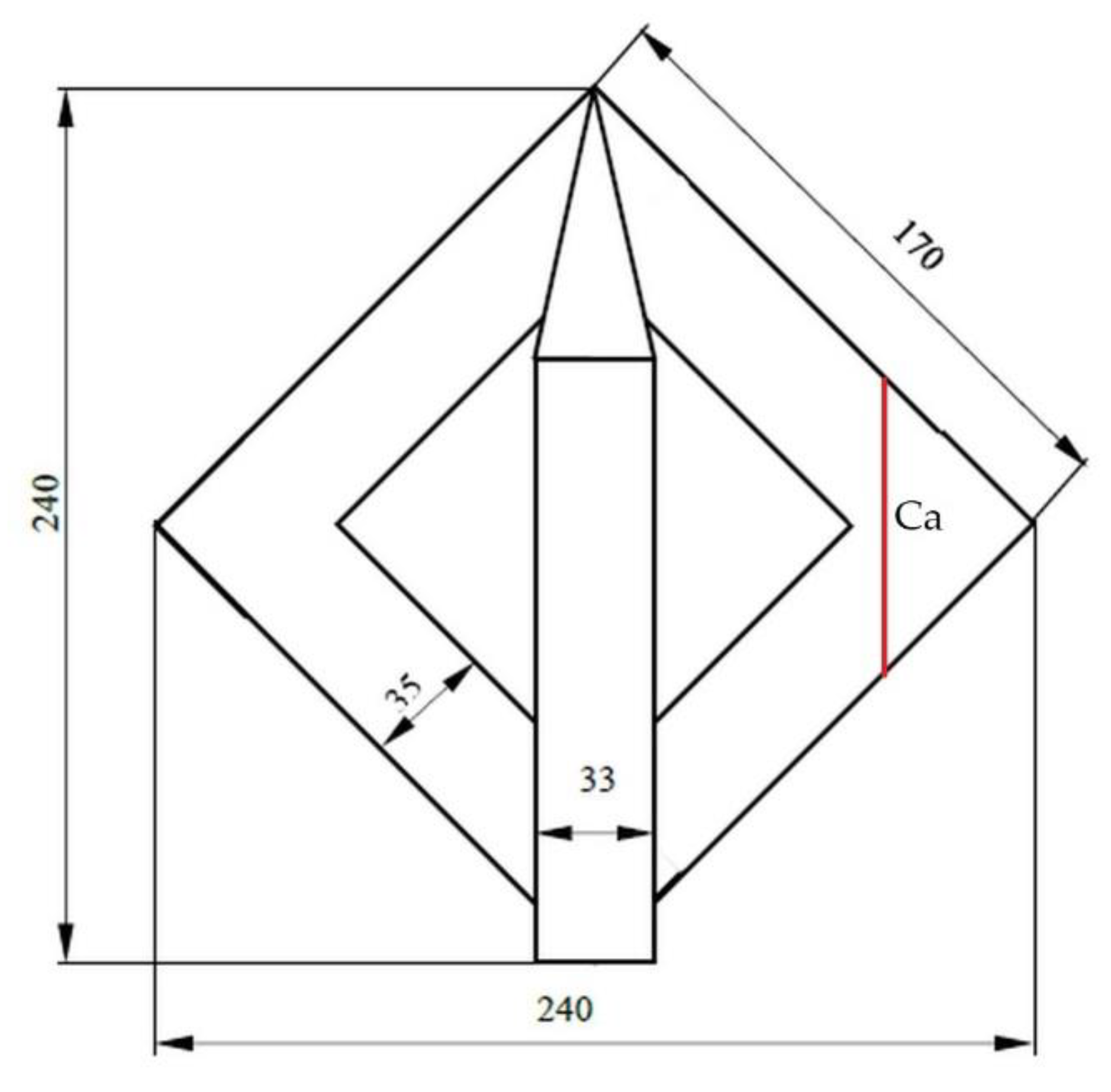
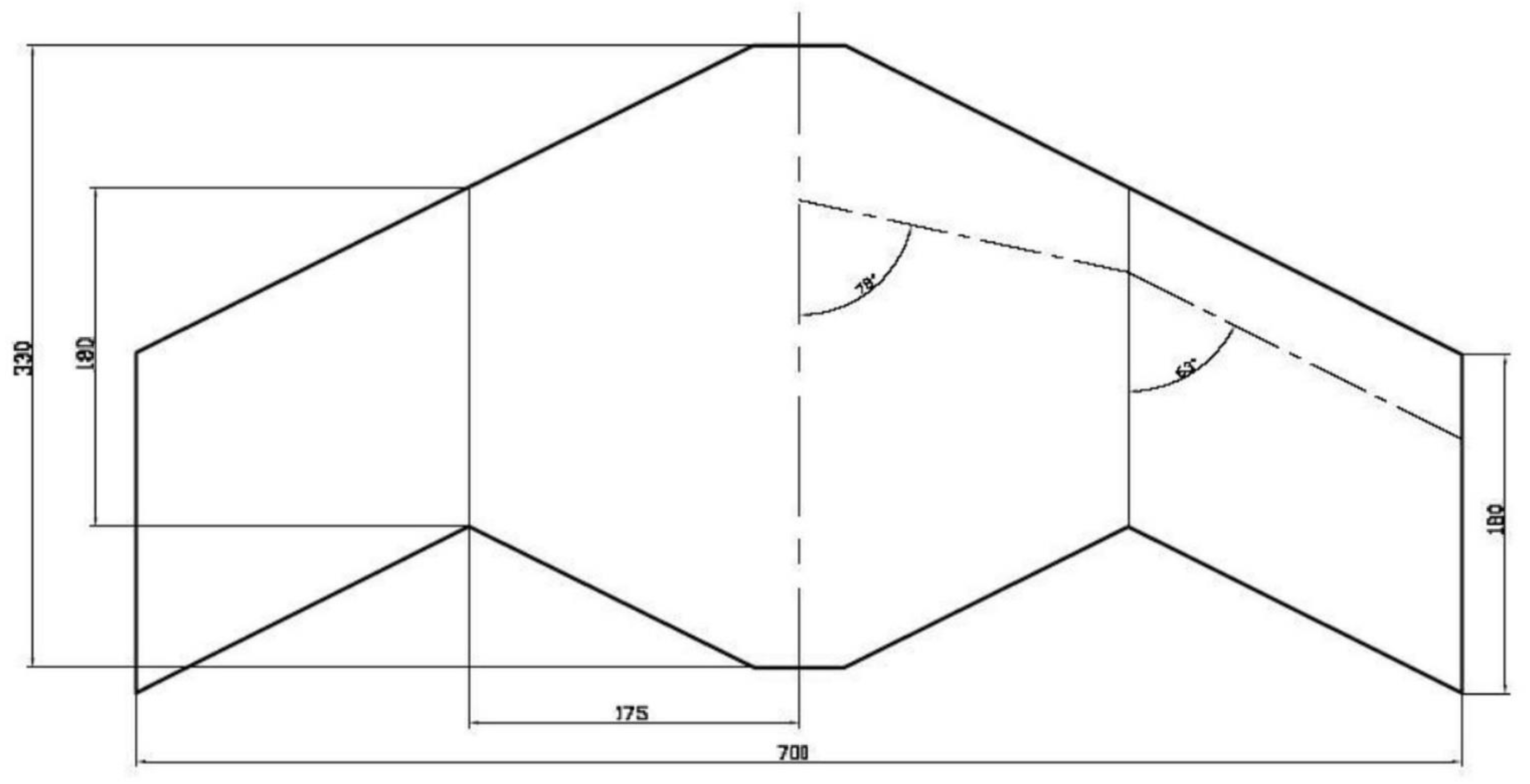
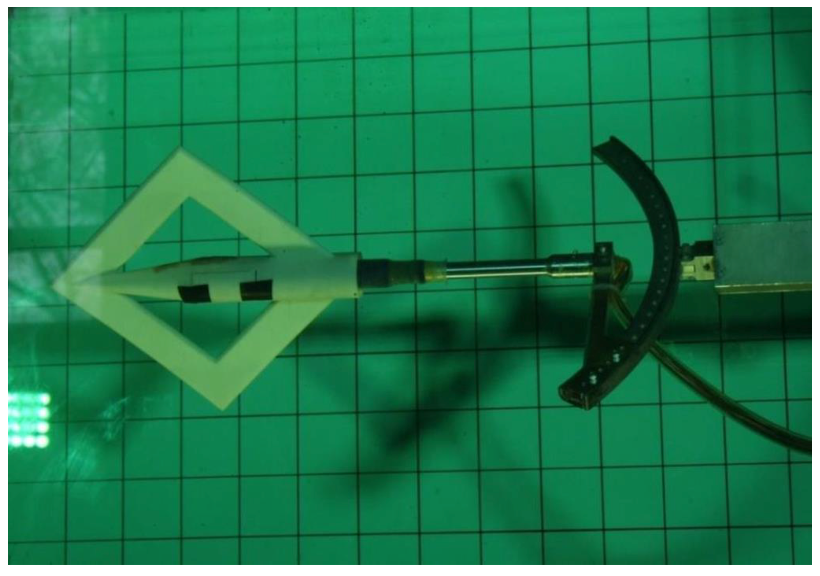
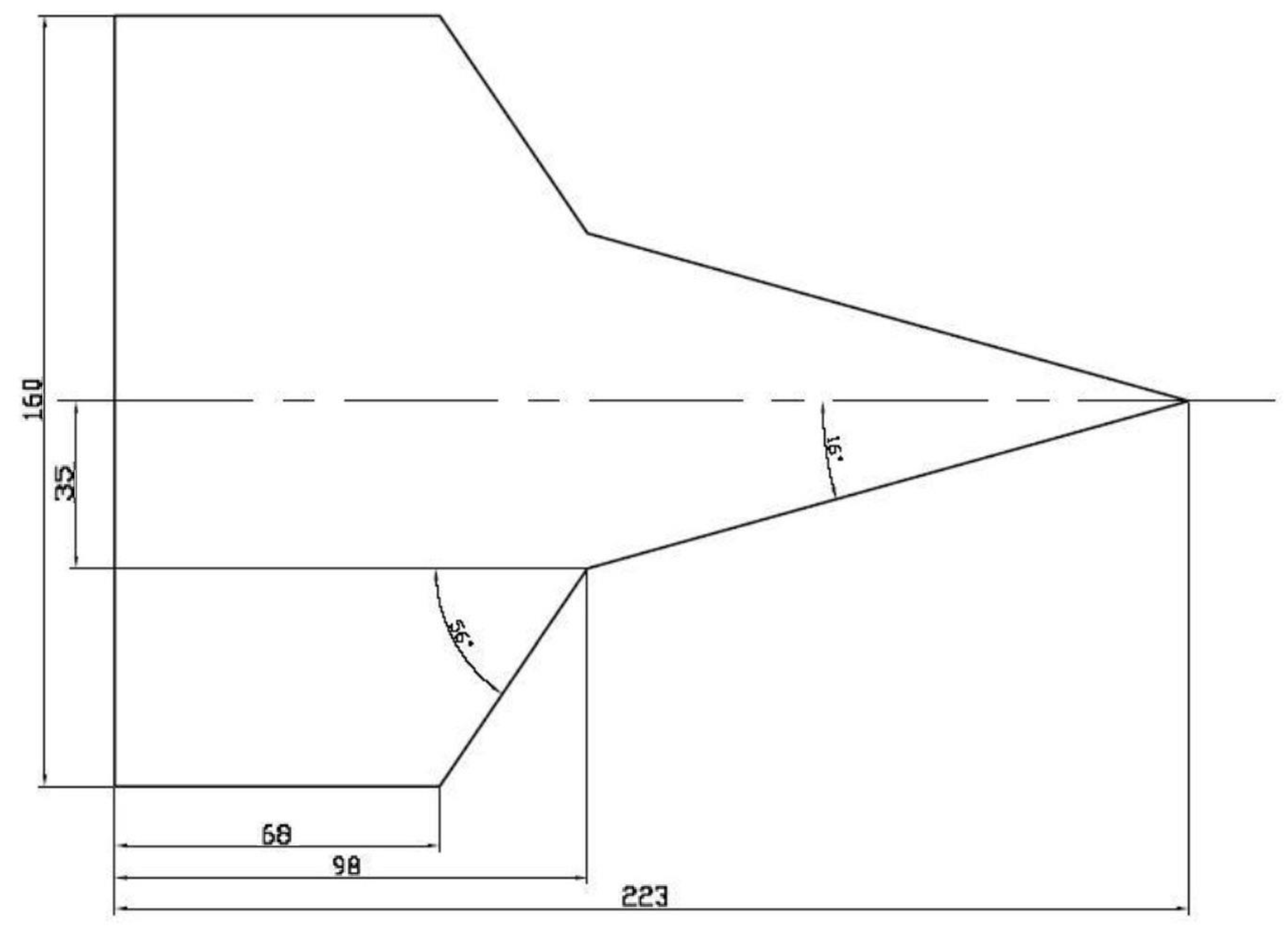
The object of the research was a model of the FlatFlyer plane. Since the water tunnel used for the test does not allow the model with the original dimensions to be placed in it, it was scaled down by five times, obtaining the dimensions shown in
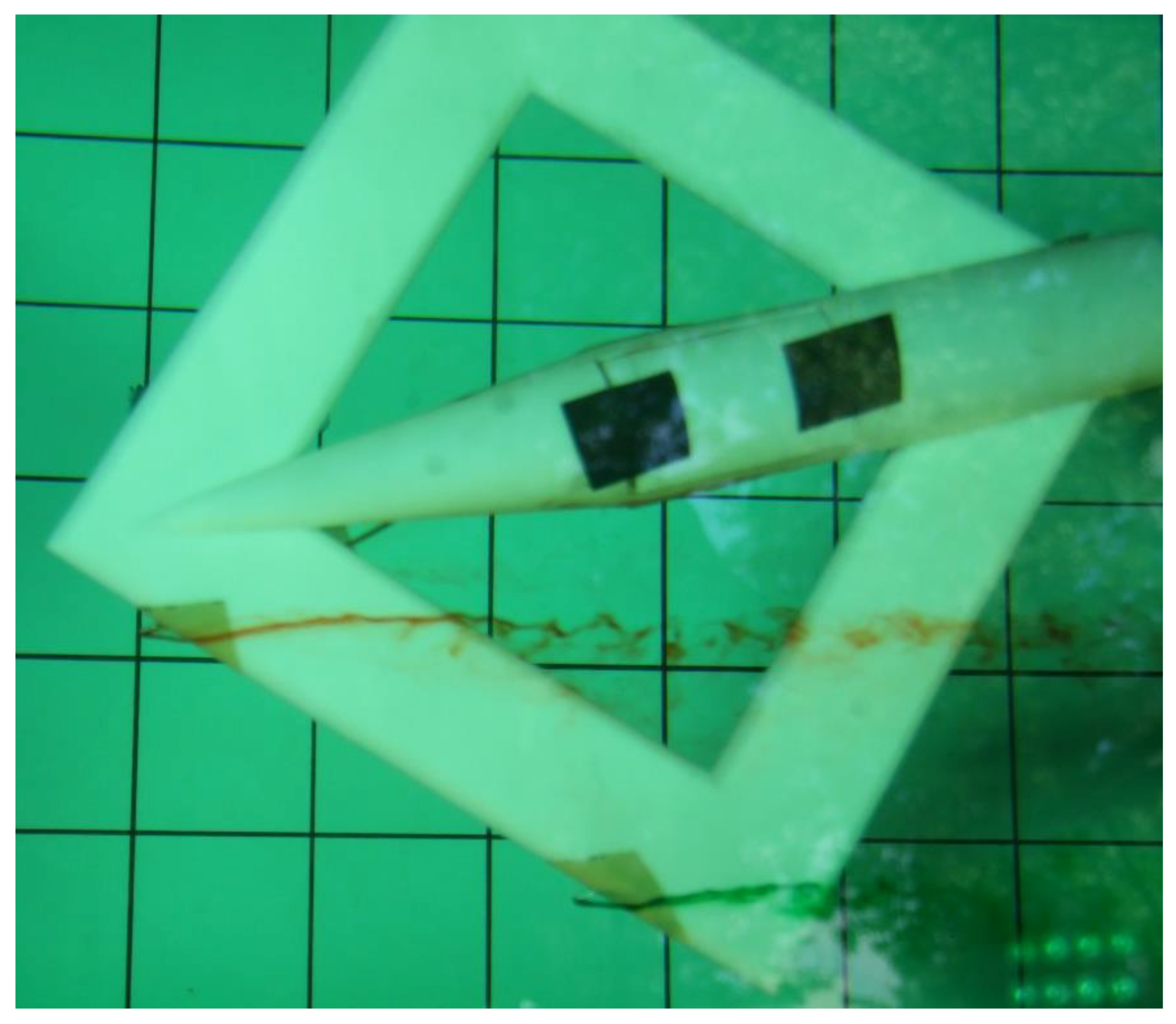
Figure 1. As the water tunnel uses a factor denser than air, this size is perfectly sufficient to obtain visible results from aerodynamic measurements. The model placed in water tunnel is made in additive printing technology, which is shown on
Figure 2.
The aerodynamic system of the aircraft is distinguished (compared with classic solutions) by two special features. The plane has two wings forming a square outline with the fuselage of circular cross-section integrated centrally along the diagonal. Another unusual feature is the use of a rectangular wing profile with sharp leading edges.
2.4. Characteristics of Experiments in a Water Tunnel
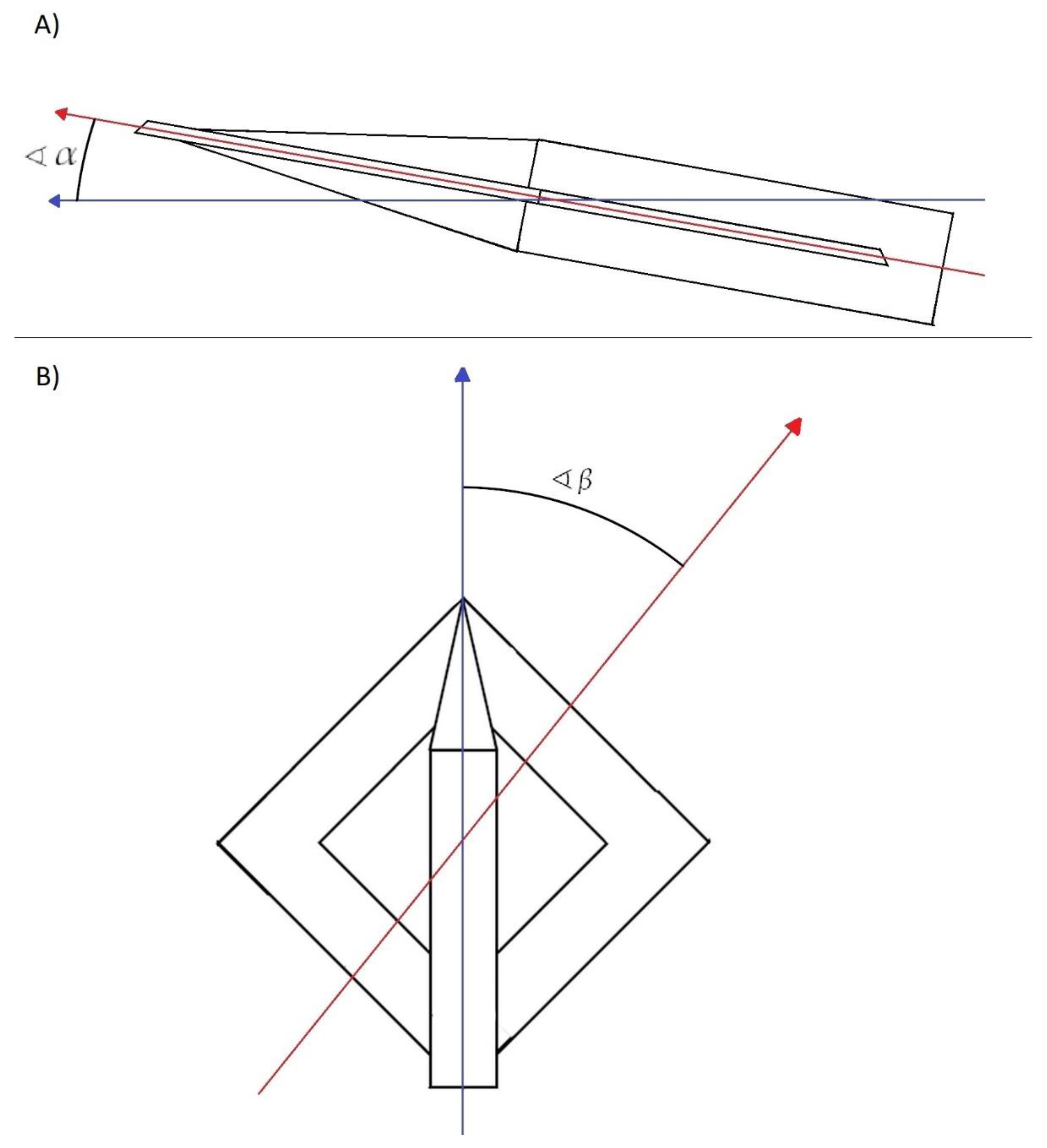
To determine the aerodynamic characteristics of the airplane model after exceeding the critical angle of attack, static 1D-Sweep (name of the test marked in water’s tunnel computer program) tests were performed. The model was attached to the bottom bracket of a water tunnel with an initial attack angle (α0) = 30°, which made it possible to study the forces and aerodynamic moments in the range of real angles (α) = (28~46)°.
The 2D-Sweep test enables the determination of static characteristics, which means that the measurements of the forces and aerodynamic moments were made in fixed positions of the model. These tests were carried out to determine the dependence of the magnitude of the aerodynamic forces on the angle of attack for different sliding angles. All tests were performed for four different velocities of water inflow, i.e., for four Reynolds numbers. Since the model was scaled down, the inflow velocities were small and oscillated between 0.21–0.26 m/s. Such an inflow velocity in a water tunnel reflects the forces that would occur in the air at a speed of approximately 3–4 m/s (the reduced–scaled model). These velocities are sufficient to determine the basic force coefficients presented in a further part of the study. The tests (
Table 1) were made for the angles of attack in the range α = (−6~32°), with the change of the angle of attack Δ α = 2° (Δ stands for angle increment), for the sliding angles in the range β = (0~14°), with the change of the angle Δ β = 2° (
Figure 3).
A total of 32 2D-Sweep static tests were performed.
3. Results
To determine the dependence of the normal force coefficient on the angle of attack, the 1D-Sweep and 2D-Sweep static tests were carried out.
The normal force can be calculated from the equation:
where:
3.1. Normal Force Coefficient CN and the Influence of Flight Speed
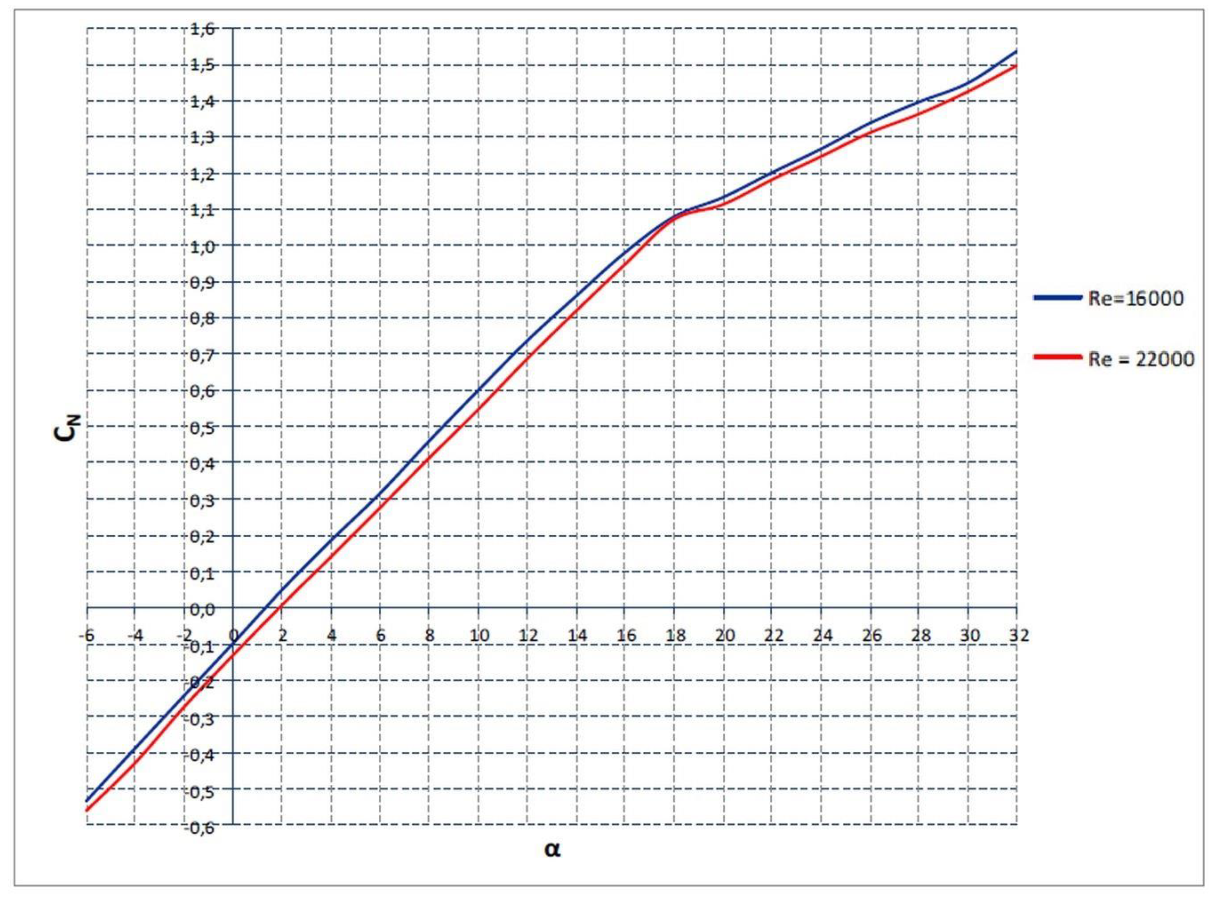
The tests were performed for four different flow velocities, so the results were obtained for four Reynolds numbers. The change in the flow velocity has a relatively small impact on the value of the normal force coefficient, i.e., the wing capacity, so only two out of the four results are presented. The other two speeds, which are not included in
Figure 4 (Re = 18,000 and Re = 20,000), take place between the blue and red lines.
As the flow velocity (airplane flight speed) increases, the coefficients of the normal force slightly decrease (
Figure 4).
3.2. Normal Force Coefficient CN and the Influence of Attack Speed and Rack Speed
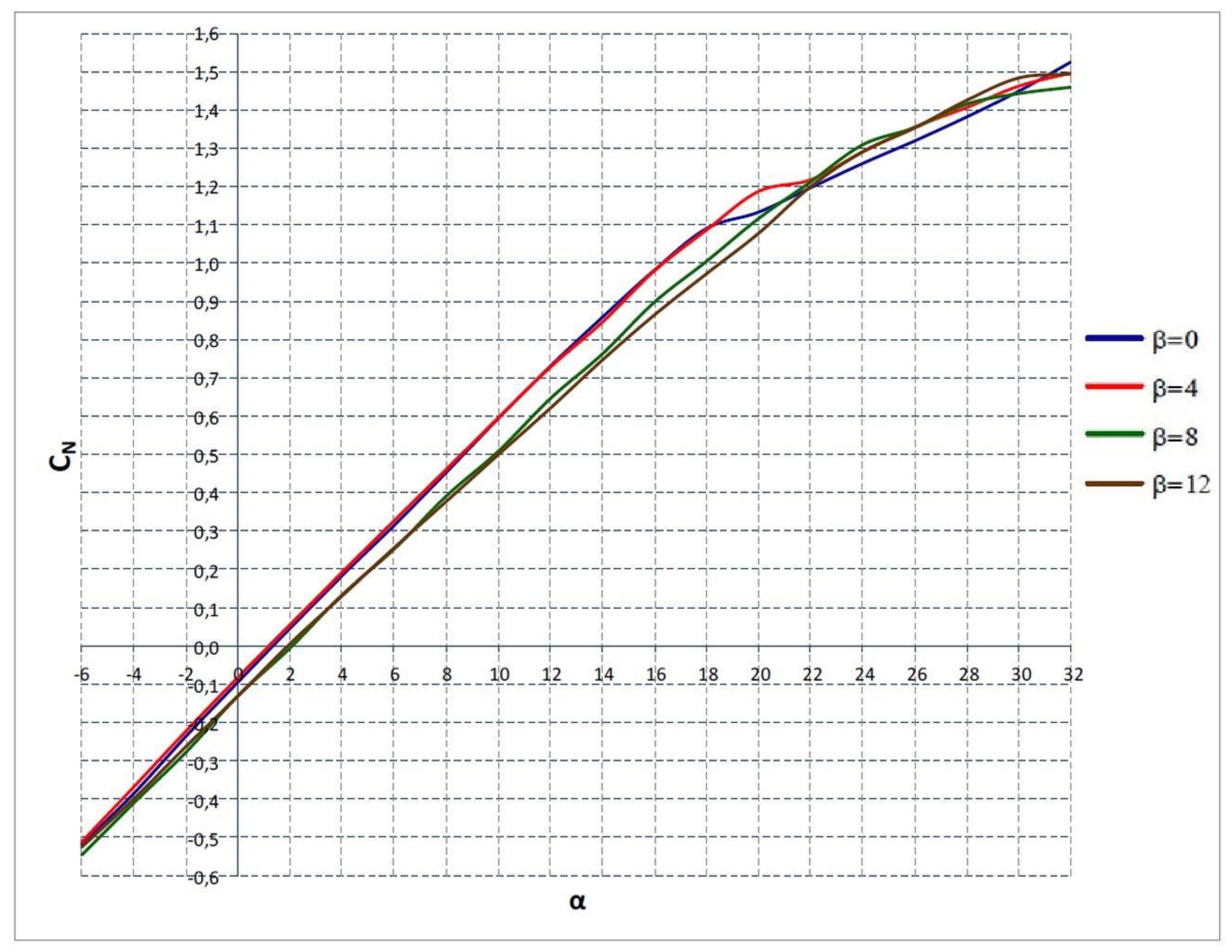
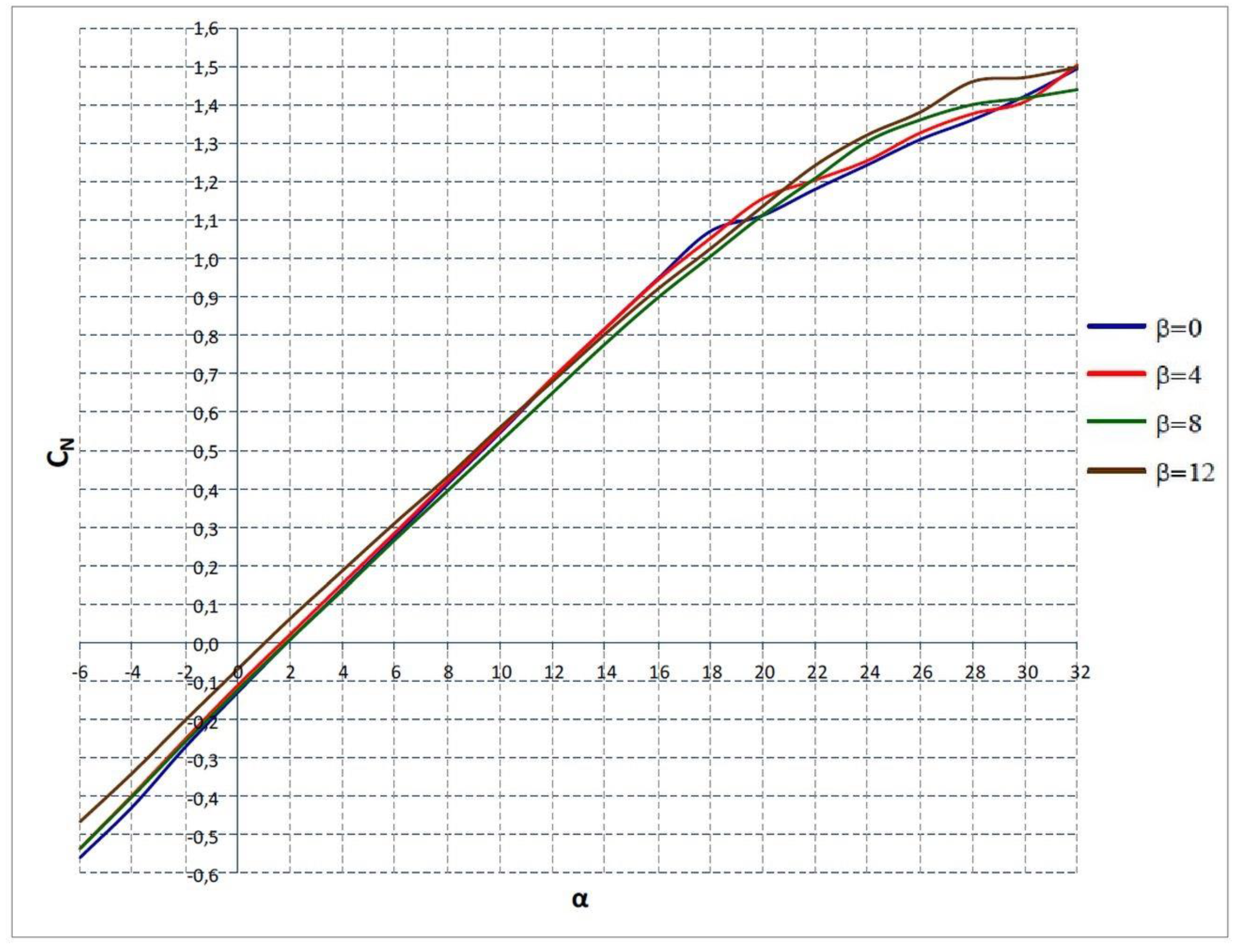
The results of the measurements make it possible to determine the course of the normal force coefficient (CN) as a function of the attack angle for various sliding angles. As the tests were performed at four water velocities (for four different Reynolds numbers), the influence of the airplane flight speed on the value of the normal force is again determined.
The normal force coefficient (C
N) changes linearly with the increase in the attack angle, up to the critical attack angle [
23]. This is a typical course for classic aviation profiles. The maximum values of the normal force coefficient indicate good characteristics of the aircraft wing’s lift capacity. Results for Reynolds numbers of 18,000 and 22,000 were shown accordingly on
Figure 5 and
Figure 6. For the remaining two values of Reynolds numbers (16,000 and 20,000), the results show similar properties for the above.
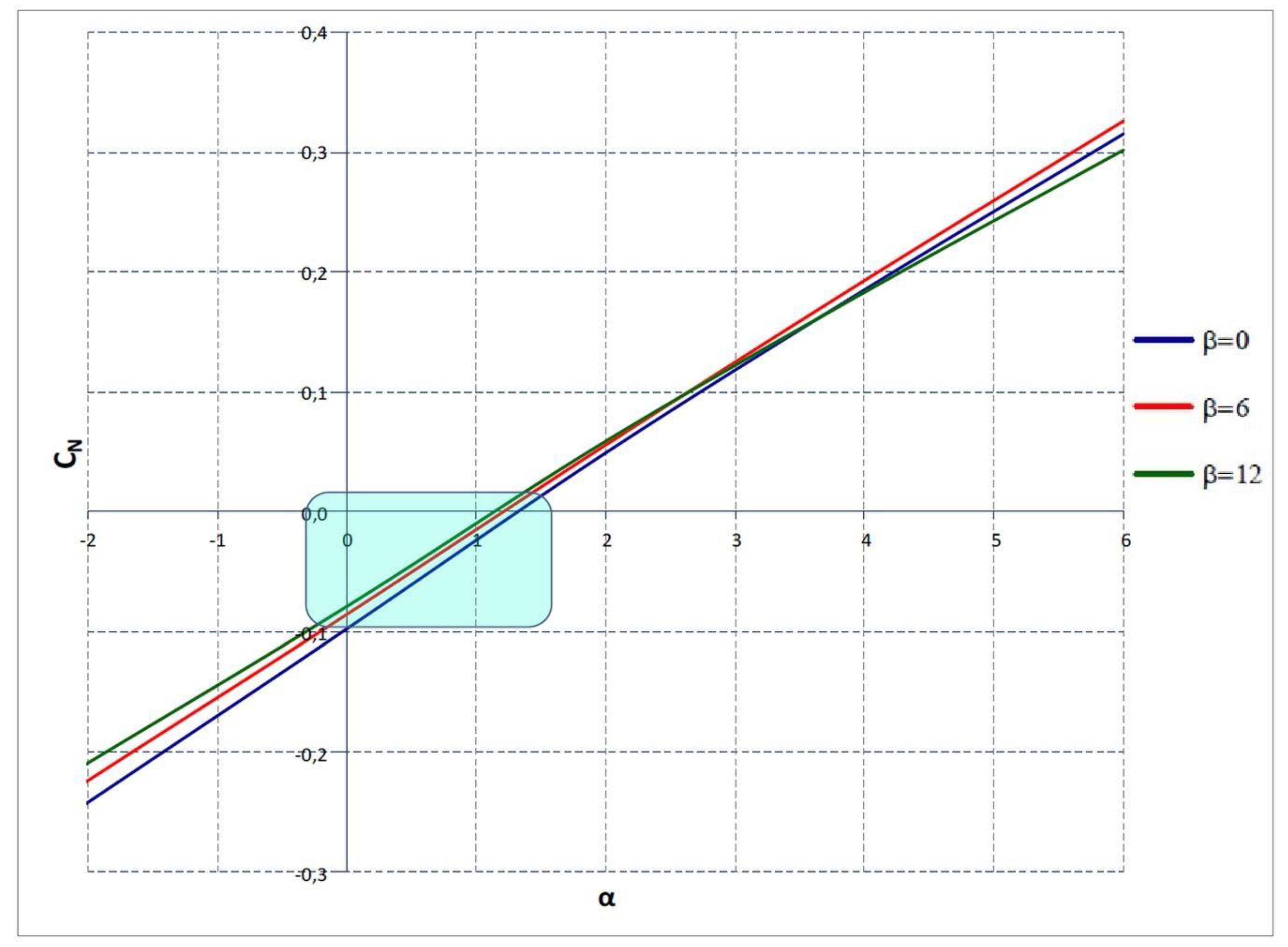
A characteristic feature of the FlatFlyer wing profile used is the fact that, unlike the classic aviation profile of an aircraft wing, for the angle of attack = 0°, the plane has negative lift values. Only at positive angles of attack are positive values of normal force obtained (
Figure 7).
The above tests show that the FlatFlyer model behaves stably in various speed ranges and does not show negative behavior from the aviation point of view. It is similar when the sliding angles are also connected to different speeds; even for values of the order of β = 12°, the normal force coefficient remains in a favorable position.
3.3. Comparison of the Basic Coefficients of the FlatFlyer Model with Other Flying Solutions
To compare the wing capacity of the tested object with airplanes with typical aerodynamic systems and classic aviation profiles, the characteristics of the normal force coefficient of three airplanes tested in a water tunnel were compiled:
- -
- -
Airplane in the Flying Wing (LS) layout (
Figure 8);
- -
Parameters of airplanes are shown in
Table 2.
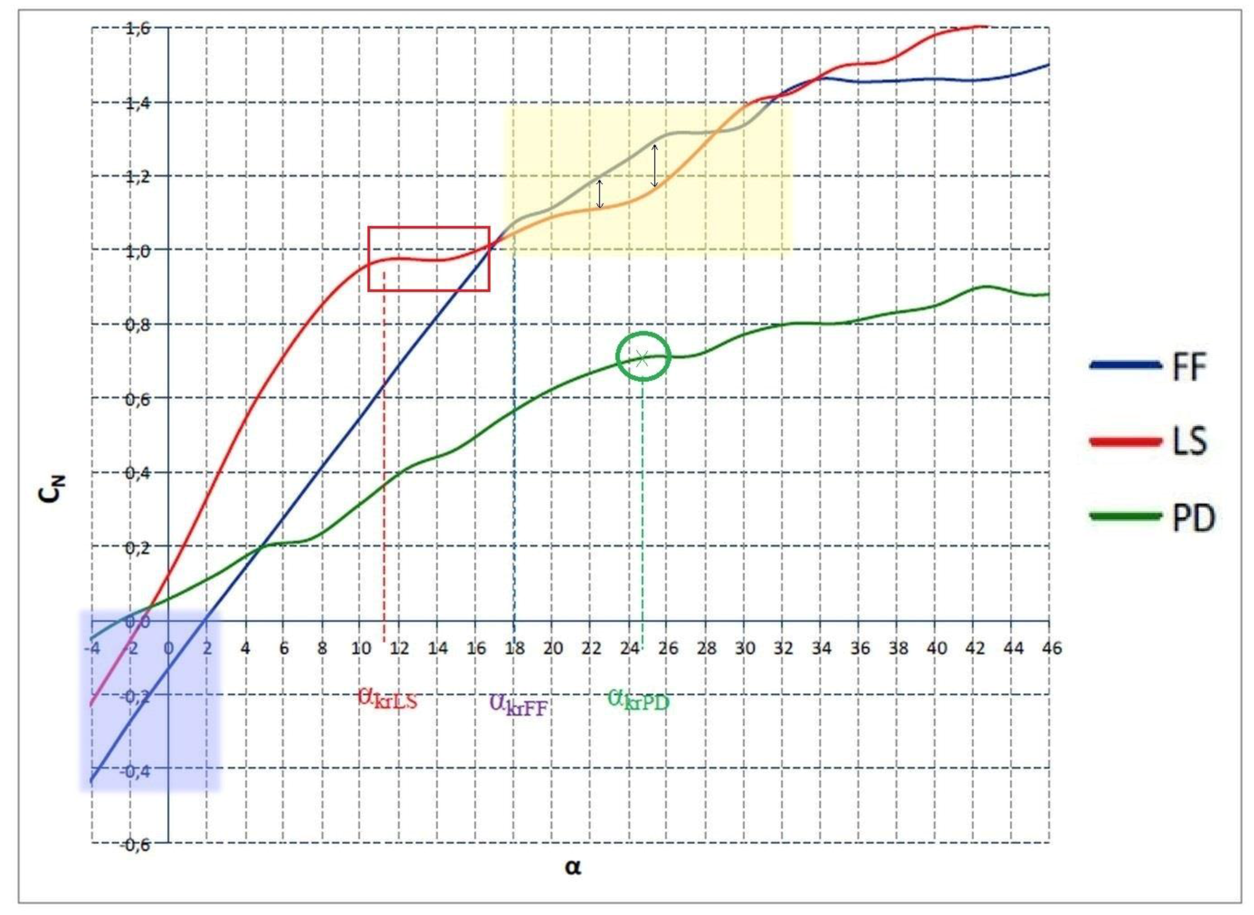
The course of the normal force coefficient as a function of the angle of attack (
Figure 10) shows that, up to the critical angle of attack, the Flying Wing airplane has the highest load capacity [
24]. The lowest C
N values are those of the Double Delta airplane model. The aerodynamic system of the FlatFlyer aircraft, thanks to the use of four wings, allows for a larger total lift surface. Therefore, even with normal force coefficients at a similar level or lower compared to classic design solutions, very good wing capacity characteristics should be expected.
The FF (FlatFlyer) airplane, compared to the LS (Flying Wing), has a much larger critical angle of attack. The highest critical angle of attack is that of the PD (Double Delta) system [
25]. The values of the critical angles of attack for the individual aircraft models (α
kr) are as follows:
- -
Flying Wing—αkrLS = 11.5°;
- -
FlatFlyer—αkrFF = 18°;
- -
Double Delta—αkrPD = 24.7°.
It is noteworthy that after exceeding the critical angle of attack, in the case of the FF aircraft, the slowest C
N growth slows down. This means that the FlatFlyer has very good aerodynamic characteristics after a stall (after exceeding the critical angle of attack) [
26]. It should be assumed that the plane will be falling slightly and that the altitude loss needed to get it out of the stall will be relatively small.
3.4. The Specificity of the Flight Phases of the FlatFlyer Model
Based on the above results, some characteristic features of the FlatFlyer model can be noticed. The basic element is the fact of obtaining a positive lift coefficient for the FF model only at the angle of attack in the range of 0~1.5° (marked in blue in
Figure 10). This state of affairs is not recorded in the case of the LS and PD models.
In flight, an optimal normal force coefficient can be expected, much greater than the PD model, but smaller than the LS model. Above a certain value of the attack angle, a reverse tendency can be noticed. The difference then oscillates at around 0.1 of the normal force coefficient (marked in yellow in
Figure 10).
On the other hand, at the angles of attack accompanying the stall, a much larger angle can be noticed that is needed to lose the lift in relation to the LS model [
27]. The PD model, on the other hand, excels here with a very high value (24.7°—marked with the green circle in
Figure 10).
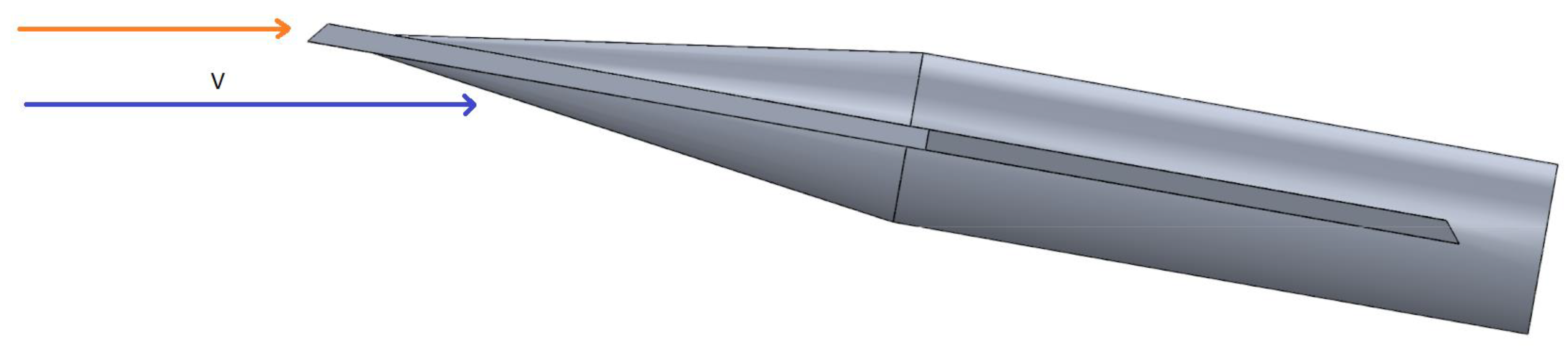
The specificity of the above observations results from two characteristic “phases” of flight of the FlatFlyer model. Such a division occurs due to its unusual design, and the lack of a classic wing profile, especially in the low-speed flight stage. In the first phase of flight (
Figure 11), so from a speed above 1 m/s until horizontal flight, it can be noticed that the model gains speed using its entire surface as the angle of attack. Thus, this shows that, to obtain the lifting force, an angle of attack greater than 0° is needed—marked in blue in
Figure 10.
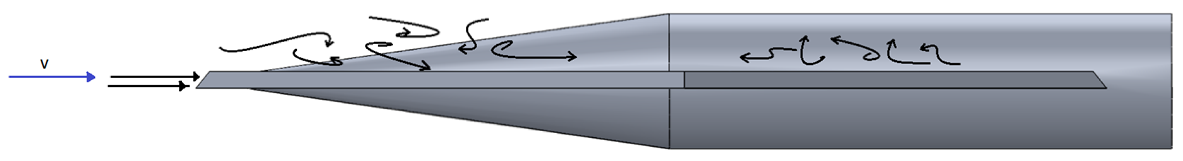
In turn, after reaching a certain speed, the model enters a horizontal flight phase and continues the flight using the cut leading edge. This causes the air stream to flow over the wing by breaking it and putting it into turbulent flow which can be noticed on
Figure 12 [
28]. At the same time, under the wing, there is a laminar flow. An additional cut between the wings causes even more air to flow back in and break it down (
Figure 13).
4. Discussion
The idea of creating a FlatFlyer model arose from the need to reflect on the future development of unmanned aerial vehicles for broad armed forces usage. The chance to equip most army units with UAVs forces us to consider whether it is possible to dramatically reduce the production costs of an unmanned aerial vehicle. It is not possible to achieve this goal without a complete simplification of the structure so that the production process is limited to the necessary minimum. The FlatFlyer model meets these assumptions—it is a simple structure that can be introduced to the market by mass production easily and fast.
Based on in-air observation of the extraordinary maneuverability of FlatFlyer, the study of its avionic properties was performed in the water channel. The presented study has drawn conclusions indicating that the model is characterized by a number of specific factors. The aircraft has a good wing lift. The course of changes in the lift of the aircraft is analogous to the use of classic airfoils, and with the FlatFlyer aircraft construction, noticeably greater critical angles of attack are observed than in other already commonly used aircraft constructions. It is worth noting that, both at low speeds and after increasing the speed, the lift coefficient changes very little, being in every elastic range and still presenting very good flight parameters. This shows that the model, in an unusual way, can operate in a very wide speed range without losing its flight stability and offering a short ground run during take-off and landing roll. The characteristics of the wing after exceeding the critical angle of attack indicate a very slight decrease in the lift capacity, which proves the very good properties of the aircraft after stalling. A slight loss of height is to be expected to bring the airplane down to a certain level flight after such an event. This is crucial from the point of safety and drone operation by people with limited experience. In a comparison to the LS model, after reaching a certain angle of attack, the lifting force registered for the LS model drops very drastically (marked with a red rectangle in
Figure 10).
The flight speed combined with the slide angle (in the range of Reynolds numbers close to Re = 20,000) has a small effect on the characteristics of the forces and aerodynamic moments, which leads to the unusual stability of the flight properties of the aircraft, not observed in other constructions.
The above conclusions resulting from the research confirm the theses discussed at the beginning of the article:
- -
High lift is achieved and a low minimum speed is required for take-off and touchdown during landing;
- -
High static stability has been achieved;
- -
The structure is resistant to falling into a corkscrew and stalling, and in the event of such an occurrence, it can get out of the situation as quickly and safely as possible.
Since a high level of flying parameters has been proved, the criteria of the development process were also confirmed, i.e., simplification of construction, reduction in the product price, and the most favorable ease of maintenance of the unmanned aerial vehicle. At the same time, this satisfies the requirements that are very important for the future development and the broad application of new aerodynamic construction by the armed forces.
The test in the water tunnel clearly shows that the model takes off and proceeds with a stable flight. In the studies, tests showed better performance and flight capabilities compared to the currently used avionic constructions.
Due to the specific flight characteristics, the FlatFlyer could be used to neutralize any other UAVs.
Author Contributions
Conceptualization, A.J.; methodology, A.J. and T.D.; validation, D.L. and A.J.; formal analysis, D.L.; investigation, A.J.; resources, T.D. and A.J.; writing—original draft preparation, D.L.; writing—review and editing, D.L. and A.J.; visualization, T.D.; supervision, A.J.; project administration, A.J. All authors have read and agreed to the published version of the manuscript.
Funding
Research was supported by Lower Silesian Innovative Fund no. 301/B, Wroclaw, PL. The European Regional Development Fund under the Regional Operational Program of the Lower Silesia Province 2014–2020.
Institutional Review Board Statement
Not applicable.
Informed Consent Statement
Not applicable.
Conflicts of Interest
The authors declare no conflict of interest.
References
- Feickert, A. The Army’s Future Combat System (FCS): Background and Issues for Congress; Library of Congress Washington DC Congressional Research Service: Washington, DC, USA, 2006. [Google Scholar]
- Gertler, J.U.S. Unmanned Aerial Systems; Library of Congress Washington DC Congressional Research Service: Washington, DC, USA, 2012. [Google Scholar]
- Woodhams, G.; Borrie, J. Armed UAVs in Conflict Escalation and Inter-State Crisis. United Nations Inst. Disarm. Res. 2018, 1–3. Available online: https://www.researchgate.net/publication/329644008_Armed_UAVs_in_Conflict_escalation_and_Inter-State_crisis (accessed on 5 May 2021).
- Lyon, D.H. A Military Perspective on Small Unmanned Aerial Vehicles. IEEE Instrum. Meas. Mag. 2004, 7, 27–31. [Google Scholar] [CrossRef]
- Barnes, M.J.; Matz, M.F. Crew Simulations for Unmanned Aerial Vehicle (UAV) Applications: Sustained Effects, Shift Factors, Interface Issues, and Crew Size. Proc. Human Factors Ergon. Soc. Annu. Meet. 1998, 42, 143–147. [Google Scholar] [CrossRef]
- Hall, R.C. Reconnaissance Drones: Their First Use in the Cold War. Air Power Hist. 2014, 61, 20–27. [Google Scholar]
- Shi, X.; Yang, C.; Xie, W.; Liang, C.; Shi, Z.; Chen, J. Anti-Drone System with Multiple Surveillance Technologies: Architecture, Implementation, and Challenges. IEEE Commun. Mag. 2018, 56, 68–74. [Google Scholar] [CrossRef]
- Zegart, A. Cheap Fights, Credible Threats: The Future of Armed Drones and Coercion. J. Strateg. Stud. 2020, 43, 6–46. [Google Scholar] [CrossRef]
- Ozdemir, U.; Aktas, Y.O.; Vuruskan, A.; Dereli, Y.; Tarhan, A.F.; Demirbag, K.; Erdem, A.; Kalaycioglu, G.D.; Ozkol, I.; Inalhan, G. Design of a Commercial Hybrid VTOL UAV System. J. Intell. Robot. Syst. 2014, 74, 371–393. [Google Scholar] [CrossRef]
- Arifianto, O.; Farhood, M. Development and Modeling of a Low-Cost Unmanned Aerial Vehicle Research Platform. J. Intell. Robot. Syst. 2015, 80, 139–164. [Google Scholar] [CrossRef]
- Panagiotou, P.; Fotiadis-Karras, S.; Yakinthos, K. Conceptual Design of a Blended Wing Body MALE UAV. Aerosp. Sci. Technol. 2018, 73, 32–47. [Google Scholar] [CrossRef]
- Russell, J. Performance and Stability of Aircraft; Butterworth–Heinemann: Oxford, UK, 1996. [Google Scholar]
- Cunis, T.; Leth, T.; Totu, L.C.; Cour-Harbo, A.L. Identification of Thrust, Lift, and Drag for Deep-Stall Flight Data of a Fixed-Wing Unmanned Aircraft. In Proceedings of the 2018 International Conference on Unmanned Aircraft Systems (ICUAS), Dallas, TX, USA, 12–15 June 2018; pp. 531–538. [Google Scholar] [CrossRef]
- Belcastro, C.; Foster, J. Aircraft Loss-of-Control Accident Analysis. In Proceedings of the AIAA Guidance, Navigation, and Control Conference, Toronto, ON, Canada, 2–5 August 2010. [Google Scholar] [CrossRef] [Green Version]
- McAlister, K.W.; Carr, L.W. Water Tunnel Visualizations of Dynamic Stall. J. Fluids Eng. 1979, 101, 376–380. [Google Scholar] [CrossRef]
- Sibilski, K.; Nowakowski, M.; Rykaczewski, D.; Szczepaniak, P.; Żyluk, A.; Sibilska-Mroziewicz, A.; Garbowski, M.; Wróblewski, W. Identification of Fixed-Wing Micro Aerial Vehicle Aerodynamic Derivatives from Dynamic Water Tunnel Tests. Aerospace 2020, 7, 116. [Google Scholar] [CrossRef]
- Yu, H.-T.; Bernal, L.; Morrison, C. Experimental Investigation of Pitch Ramp-Hold-Return Motion of Flat Plates at Low Reynolds Number. In Proceedings of the 50th AIAA Aerospace Sciences Meeting including the New Horizons Forum and Aerospace Exposition, Nashville, TN, USA, 9–12 January 2012. [Google Scholar] [CrossRef] [Green Version]
- Morelli, E.A. Multiple Input Design for Real-Time Parameter Estimation in the Frequency Domain. IFAC Proc. Vol. 2003, 36, 639–644. [Google Scholar] [CrossRef] [Green Version]
- Kerho, M.; Kramer, B.R. Research Water Tunnels—Specification; Rolling Hills Research Corporation (RHRC): El Segundo, CA, USA, 2003. [Google Scholar]
- Suarez, C.; Malcolm, G. Water Tunnel Force and Moment Measurements on an F/A-18. In Proceedings of the 12th Applied Aerodynamics Conference, Colorado Springs, CO, USA, 20–23 June 1994; American Institute of Aeronautics and Astronautics: Reston, VA, USA, 1994. [Google Scholar] [CrossRef]
- Tyan, M.; Kim, M.; Pham, V.; Choi, C.K.; Nguyen, T.L.; Lee, J.-W. Development of Advanced Aerodynamic Data Fusion Techniques for Flight Simulation Database Construction. In Proceedings of the 2018 Modeling and Simulation Technologies Conference, Atlanta, GA, USA, 25–29 June 2018; American Institute of Aeronautics and Astronautics: Reston, VA, USA, 2018. [Google Scholar] [CrossRef]
- Alhosseinihamedani, B.; Naguib, A.M.; Koochesfahani, M.M. Reynolds Number Effect on Lift Characteristics of an Airfoil Translating Across a Non-Uniform Approach Flow. In Proceedings of the AIAA Scitech 2019 Forum, San Diego, CA, USA, 7–11 January 2019; 2019. [Google Scholar] [CrossRef]
- Falkovich, G. Fluid Mechanics: A Short Course for Physicists; Cambridge University Press: Cambridge, UK, 2011. [Google Scholar] [CrossRef]
- Putranto, T.; Sulisetyono, A. Lift-Drag Coefficient and Form Factor Analyses of Hydrofoil Due to the Shape and Angle of Attack. Int. J. Appl. Eng. Res. 2017, 12, 11152–11156. [Google Scholar]
- Esteban, S. Static and Dynamic Analysis of an Unconventional Plane–Flying Wing. In Proceedings of the AIAA Atmospheric Flight Mechanics Conference and Exhibit, Montreal, QC, Canada, 6–9 August 2001. [Google Scholar] [CrossRef] [Green Version]
- Karasu, İ.; Durhasan, T. Flow Characteristics over Double Delta Wings at Low Reynolds Numbers. J. Aerosp. Eng. 2020, 33, 04020038. [Google Scholar] [CrossRef]
- Prisacariu, V.; Boşcoianu, C.; Cîrciu, I.; Boşcoianu, M. The Limits of Downsizing-A Critical Analysis of the Limits of the Agile Flying Wing MiniUAV. Appl. Mech. Mater. 2015, 772, 424–429. [Google Scholar] [CrossRef]
- Sigurdson, L.W. The Structure and Control of a Turbulent Reattaching Flow. J. Fluid Mech. 1995, 298, 139–165. [Google Scholar] [CrossRef]
| Publisher’s Note: MDPI stays neutral with regard to jurisdictional claims in published maps and institutional affiliations. |
© 2021 by the authors. Licensee MDPI, Basel, Switzerland. This article is an open access article distributed under the terms and conditions of the Creative Commons Attribution (CC BY) license (https://creativecommons.org/licenses/by/4.0/).


