Featured Application
In this research study, a new adaptive model of the thorax for peoples with spinal disabilities was proposed for the application of performance clothing design. The adaptive model was designed from the spine and follows the deformation of the spine to adapt the thorax skeleton according to spinal column deformation using the images from the EOS medical scanner. The developed adaptive thorax model helps to design a basic bodice adapted to the patient’s evolving morphology through detecting the anthropometric points from certain bone parts of the skeleton.
Abstract
Peoples with spinal disability face a huge problem in the design and development of ergonomically fitted and comfortable clothing. Various research studies on the design and developments of functional clothing for scoliosis patients consider their morphological shapes. However, developing appropriate models of the complicated and deformed anatomical shape of the patient in 3D digitization technologies makes it possible to design a comfortable and fitted garment. The current paper proposes a method for developing a fully parametric 3D adaptive model of the thorax of a patient suffering from scoliosis. The model is designed from the spine and follows the deformation of the spine to adapt the thorax skeleton according to the temporal evolution of the spinal column deformation. The integration of the model of the thorax, adjusted to the patient’s data, enables the chain of acquisition, processing, and global model to be validated. The fit of the model could be improved for the different bones and it is possible to modify the angles of the spine to see the evolution of the disease. The developed model greatly helps to further detect anthropometric points from certain bone parts of the skeleton to design a basic bodice adapted to the patient’s evolving morphology.
1. Introduction
The spinal disability scoliosis is a multifactorial three-dimensional (3D) spinal deformity that is directly be related to vertebral deviations in the coronal, sagittal, and horizontal planes. Such deformity later shows an uneven structure on the thorax, skeleton, and then the overall morphologies of the body shape. Understanding the structures of the thorax and overall skeleton of scoliosis patients could greatly help the medical and surgical operations process. Modelling of the human thorax has been showing great advancements in the past 20 years [1]. The involvement of computer-aided design (CAD), with various computational and analytical tools, plays a great role in the design and customizations of clothing [2]. In particular, 3D designing software was applied to improve the garment design process by overcoming the limitations of ordinary 2D design methods by generating virtual 3D models [3,4,5]. The structural model of the human rib cage and abdomen, with different geometrical and functional features, were also studied to understand respiratory mechanics. Based on the study, the developed model’s predictions help to suggest the coordinated activity of rib cage musculature and the diaphragm to expand the respiratory system [6]. Even though the thorax has been studied for its involvement in the physiological mechanism leading to specific gas exchange, another study brings a new method to analyze the costovertebral joint complex kinematics from clinically available retrospective data [7]. The different effects of different thorax models, with either conductivity or complex conductivity on the reconstructed images and ventilation indices, were also studied [8]. A study also proposed and developed the dynamic 3D model of a human thorax to emulate the complexity and movement of a human torso to detect changes in lung fluid content as well as monitoring heart and respiratory rates [9]. Besides using the developed 3D model, simulations were performed, and the waveforms generated from these simulations were found to be like results from human clinical trials. The developed model helped to facilitate the detailed examination of the sensitivity of the CP-Stethoscope measurement to sensor locations on the human body. Another research study also worked on thorax deformation by modelling the respiratory muscles according to continuum mechanics and muscle contractions [10]. The reproduction of representative motions of the ribs and the comparison of the thorax deformations demonstrated the effectiveness of the proposed approach. The authors claimed that it provided a platform for establishing a computational mechanics model of the human respiratory system. Another study attempted to describe the ribs and vertebrae of the human rib cage under the assumption that the individual elements of the rib cage do not deform significantly [11].
Apart from the medical applications, understanding the structures of the overall thorax, skeleton and morphological shapes of specific scoliosis patients is very important for developing comfortable and ergonomic performance clothing. For example, modelling the human skeleton and morphological shapes are one of the important elements in defining and developing proper garment design. Several researchers have proposed a human body model for garment design solution based on parameterization algorithms and other related methods [12,13,14,15,16,17,18]. However, designing and developing a customized apparel product for disabled people is a very complex process and it is difficult to achieve proper sizing, fit, performance and comfort. Wearing improper fitting and uncomfortable clothing could also lead to not only lower performance and unpleasant appearance, but also to serious musculoskeletal pain. To tackle this issue, researchers, engineers, and designers have worked hard to bring about different methods for the proper designing of functional clothing for such peoples. One study tried to devise a process to design apparel products for persons suffering from locomotory disabilities requiring the use of a wheelchair [19]. It claimed that a general direction on manufacturing clothing that meet the requirements must focus on the needs of the persons to achieve superior standards. The current challenges and exploration of the need for readily available adaptive garments for hemiparesis or partial paralysis patients were also mapped [20].
Moreover, various researchers have focused on developing an adaptive garment for scoliosis patients. One study explored a new way to design and produce a virtual prototype of a garment adapted for peoples with scoliosis [21]. The work applied advanced virtual tools and methods, including CASP (Curvature, Accelerator, Symmetry, Proportionality), which could be adapted to the 3D body model. Using the surface of the trunk, another study also analyzed the scoliosis curve in 3D using a noninvasive multi-head digitizing system [22]. Another study evaluated the three-dimensional (3D) characteristics of spine deformity in patients with non-idiopathic scoliosis compared with that observed in patients with adolescent idiopathic scoliosis (AIS) [23]. Another new top view was also designed for patients with idiopathic scoliosis to display their spine as if the observer were above and looking down on the patient using computerized spinal analysis [24]. Recently, a researcher was also dedicatedly working to develop a full garment designing system for the specific consumer’s morphological shape with atypical physical deformations using non-adaptive 3D human modelling [25,26,27]. Such modelling processes are very time-consuming to generate garments, not only when the patient’s body changes through time but also for patients with different morphologic problems. Designing a garment for the different variations of morphological problems is a huge problem. This could be solved by integrating the full skeleton and anthropometric point, as, in general, it is a position of the bone and the connection between morphologic point and anthropometric point that is used during the modelling process. In general, previous works showed the feasibility of digitally creating in 3D a basic bodice for a person suffering from scoliosis. From the 3D scan of the person, the researchers can detect and use anthropometric points and morphological curves (waist, chest and under the chest) to spatially define the patterns of the basic bodice. One of the major problems of this method is that the detection of these different markings and data are done manually and are therefore subject to misinterpretation. Our latest work has brought a novel designing technique to develop an adaptive 3D model of the complicated anatomical shape of the human vertebrae using 3D digitization technologies for scoliosis patients [28]. It was also proposed that the adaptive model should further integrate with the full thorax, skeleton, and body shapes of scoliosis patients to develop not only easy garment design process but also to produce comfortable performance garments.
The purpose of this research is to develop a fully parametric 3D adaptive model of the skeleton of the thorax of a patient suffering from scoliosis. The method uses the human skeleton to automatically detect the spatial position of the anthropometric points and morphological curves necessary for the creation of the basic bodice. This will help to automatically generate the basic bodice and can then be more easily modified according to the style of clothing to be created.
2. Methods
2.1. Trunk Analysis
A morphological analysis of each entity of the trunk must be carried out to set up the different generic models of the thorax and the scapular belt, which will be connected to the model of the spine.
2.1.1. The Thorax
One of the essential functions of the rib cage is to protect the vital organs of the human body, including the lungs, heart, esophagus, trachea and bronchial tubes. This protection is conical in shape to adapt perfectly to the overall shape of these different vital organs, guided essentially by the shape of the lungs. Normally, the rib cage is made up of 12 pairs of ribs and classified into three categories: true, false, and floating ribs as shown in Figure 1a. The first seven ribs (true ribs) are connected to the sternum through a fibrous tissue called costal cartilage. It is used to manage the volume variations of the rib cage during the inhalation and exhalation phases of the air in the lungs. The three false ribs are connected indirectly to the sternum via the seventh costal cartilage. The last two floating (distal) ribs are not connected to the sternum. Each rib also articulates on the spine (Figure 1b) (costovertebral joints) with two dorsal vertebrae (Figure 2a). Apart from this first rib, the anatomy of the ribs (Figure 2b) includes the vertebral end (1), head (2), neck (3), tubercle (4), angle (5), the body of the shaft (6), shaft (7), and the sternal end (8).
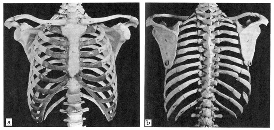
Figure 1.
The frontal (a) and dorsal (b) view of the human thorax.
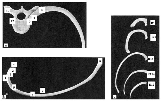
Figure 2.
The (a) articulation of vertebra and left rib, superior, (b) right central and superior view of the rib, and (c) comparative view of ribs.
Depending on their position, the ribs appear to be very different based on their shape and method of attachment to the vertebrae and sternum (Figure 2c). Starting from the rib at the top of the thorax, the first rib (R1) is relatively short, flat, broad, and crescent-shaped with one joint facet. Another important element of the rib cage is the sternum located on the midline of the ventral surface of the chest and composed of three atypically shaped bones: the manubrium sternal (1), the body (2), and the xiphoid process (3), as shown in Figure 3a.
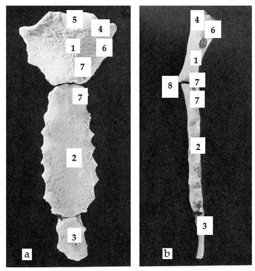
Figure 3.
The anterior view (a), and the left lateral view (b) of the sternum.
The body (2), about twice the size of the manubrium and generally thinner (Figure 3b), is divided into 4 segments and each segment joint is marked by a costal notch to which the costal cartilage of the 5 central ribs (R3 to R7) attach.
2.1.2. The Shoulder Girdle
Although the manubrium is a bony part of the sternum, it is one of the three bones that make up the shoulder girdle, i.e., the clavicles, the shoulder blades, and the manubrium. The shoulder girdle attaches the upper limbs to the upper part of the sternum and contributes to the mobility of the arm through the humerus. It also contributes to the orientation of the scapula via the joint between the manubrium and the clavicle. The anatomy of the clavicle can be summarized as the sternal facet (1), shaft (2), the acromial portion (3), attachment for the deltoid muscle (4), acromial facet (5), costal tubercle (6), conoid tubercle (7), trapezoid oblique line (8), and the groove for the subclavius muscle (9), as shown in Figure 4.
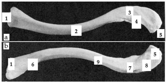
Figure 4.
The left superior view (a) and the left inferior view (b) of the clavicle.
The scapula can be compared to a large flat triangle at the back of the shoulder between ribs R2 and R7 as shown in Figure 5a–c. The anatomy of the ventral scapula (Figure 5a) can be designated as the head (1), neck (2), body (3), coracoid process (4), subscapular fossa (5), lateral line (6), lateral border (7), vertebral border (8), inferior angle (9), superior angle (10), suprascapular notch (11), infraglenoid tubercle (12), glenoid cavity (13), and tubercle for the coracoclavicular ligament (14). Similarly, the anatomy of the dorsal scapula (Figure 5c) can also be represented by the spine (1), supraspinous fossa (2), infraspinous fossa (3), acromion process (4), and greater scapular notch (5). The anatomy of the lateral scapula (Figure 5b) can be summed up as follows: glenoid cavity (1), acromion process (2), coracoid process (3), and greater scapular notch (4).
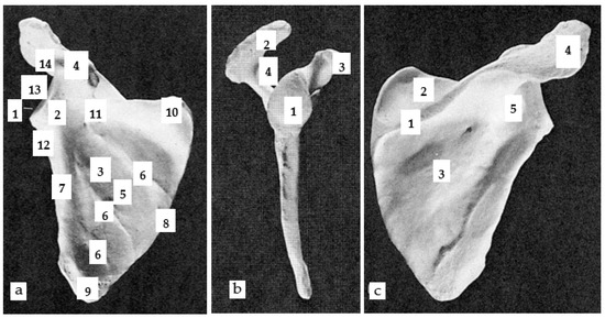
Figure 5.
The (a) right ventral view, (b) right lateral view and (c) right dorsal view of scapula.
2.2. 3D Adaptive Thorax Model
To facilitate the modelling process, the scoliosis patient was scanned in the Human Solutions body scanner. The data was then imported from the attained scanned body shape to software called Rapid Form. This software allowed us to edit and correct the defects of the imported 3D meshed object. Later, the cleaned data from the scanner were then imported onto the person’s surface model, representing the outer shell of their body into the 3D Design Concept software that was used to create our spine model.
2.2.1. Generic Model–Ribs Model
Despite the few differences between the first two ribs (R1 & R2), the central ribs (R3 to R9 and R10), and the ribs (R11 & R12), the study set up a generic model identical for all vertebrae. The integration of morphological parameters, as shown in Figure 6 (green dimensions), considered the morphological differences of each vertebra in the generic model.
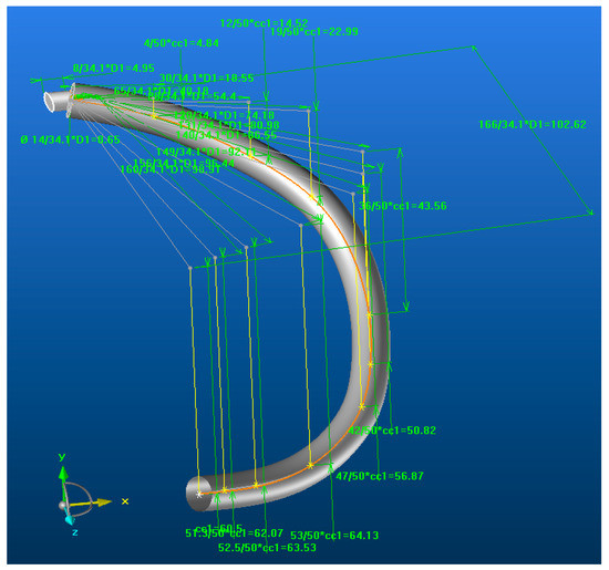
Figure 6.
The adaptive models of the rib.
This model can also be applied to people of different statures as dimensional parameters are also integrated into the model. The parameter Dn (n is the number of a vertebra) made it possible to manage the overall dimension of a rib with the dimension of the vertebra (n) associated with it, which itself depended on the dimension of the spine. This parameter managed the differences in stature between each person. The parameter ccx allowed managing of the relative dimension of a rib with another rib for the same body. The multiplicative coefficients assigned to the ccx parameters made it possible to manage the morphology of the rib in 3D.
Thus, in the transverse plane, these coefficients controlled the dimension of each grey line, i.e., the morphology of the orange curve. In the vertical planes of each mark affected at the end of these different grey lines, the coefficients ccx controlled the dimension of each yellow line, i.e., of the morphology of the orange curve (relative to its projection on the sagittal plane). This orange curve represented the median curve of the coast in its initial state without deformation. The attachment of each rib to the vertebra associated with it (common vertebra) was carried out identically by a cylindrical shape of variable size. The hypothesis was that the 3D evolution of the position of a rib depends mainly on its current rib.
As the vertebrae, ribs and sternum form a closed cage by the connection of these different bony parts, the dimension of this model was also impacted by the width (Sx) of the sternum, as shown in Figure 7a. The distance (Sn) between two ribs of the same rank (n) controlled the extreme position of each of the ribs of the same rank connected to the sternum. During modelling, the deformation of the costal cartilage between the ribs and the sternum was not considered to integrate it into the continuity of each rib at its extremity (Figure 7b). To impose a limit of elasticity, a Pe point was positioned on the orange curve representing the 3D course of the hill before its deformation. A new grey curve followed this orange curve from point 1 to point Pe and ended directly at end 2 (point hooked to the sternum).
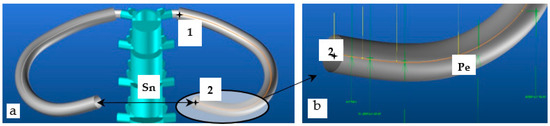
Figure 7.
The (a) developed similar ribs by sternum width Dx, and (b) the elasticity zone of the costal cartilage.
This grey curve represented the median curve of the rib with an integrated deformation zone at its end. This other curve was then used to impose a new course of the rib with a future integrated deformation and ensured that the generic rib model was only deformed in this area, which is like the costal cartilage when the spine is deformed.
2.2.2. Generic Model–Sternum Model
The sternum, composed of three distinct parts, was modelled in two parts: the manubrium sternal and the body + the xiphoid process. As the thickness between the body and the xiphoid process is relatively close, these two bony parts were merged into a single part (Figure 8a,b). On the other hand, merging was not possible with the manubrium since the manubrium and the body are articulated with the sternal angle and the thickness of the manubrium is greater. However, the modelling did not consider this difference in thickness as it does not influence the intended final application.
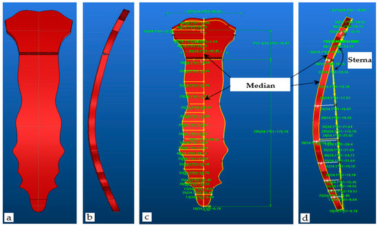
Figure 8.
The (a,c) anterior view, and (b,d) left lateral view of the adaptive sternum.
The model developed is an adaptive model that must be parameterized according to the stature of each person. The R1 rib, being the main rib attached to the manubrium, allowed us to position not only the manubrium but also the sternum in 3D. The first dorsal vertebra, being the vertebra of attachment of the R1 rib and parametrized by D1, was decided to manage the global dimension of the sternum by the same parameter D1 (Figure 8). Following the same principle as the different ribs, the multiplicative coefficients assigned to the different dimensions parameterized by D1 made it possible to manage the morphology of the sternum in 3D by employing the yellow contours (Figure 8c). These contours are defined in two planes to respect the sternal angle (Figure 8d). Certain sternums with a slight curvature in the sagittal plane and two curved yellow median contours (Figure 8c,d) have therefore been integrated into the manubrium and body models to consider this 3D morphological specificity.
2.2.3. Generic Model–Clavicle Model
The clavicle model followed a modelling strategy close to the coasts from the morphological point of view and to that of the sternum on the dimensional aspect. It is an adaptive model which must also be parameterized according to the stature of each person. With the same reasons defined above for the sternum, the global dimension of the clavicle by the parameter D1 (Figure 9b) were defined. The multiplicative coefficients assigned to the different dimensions parameterized by D1 made it possible to manage the morphology of the clavicle in 3D (Figure 9a). Thus, in the transverse plane, these coefficients controlled the dimension of each grey line (the morphology of the white curve). In the vertical planes of each mark assigned at the end of these different grey lines, the coefficients ccx controlled the dimension of each yellow line (the morphology of the white curve in other planes). Such a white curve represents the median curve of the clavicle. An adapted parametrization of these two types of lines makes it possible to respect the very significant S-shape of the clavicle and adjusted it to the correct dimensions when the model is placed inside the body surface obtained by the body scanner.
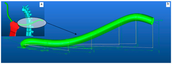
Figure 9.
Adaptive scapula model (a) global dimension of the clavicle by the parameter D1 and (b) a zoomed morphology of the clavicle in 3D view.
2.2.4. Generic Model–Scapula Mode
It is a complex model composed of three sub-models to describe the three bone parts, namely the supraspinous and infraspinous fossa (1), the spine with acromion process (2), and the coracoid process (3) as shown in Figure 10. The scapula modelling process started with the design of the two upper and lower triangles, whose characteristic shape is defined by the three edges (upper, medial, and lateral) managed by the three associated angles (upper, medial, and lateral). Figure 11 presents an improved version of the outer shape of the supraspinous and infraspinous fossa defined by two orange contours (1) relative to the upper and lower parts. A pivot axis (2: yellow line) joins them and manages the angle between these two entities to obtain a global shape of the model which follows the morphology of the ribs, i.e., the convexity of the thorax.
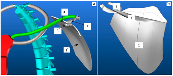
Figure 10.
The rib R1, sternum, clavicle, scapula (a) and scapula (b) of the vertebra.
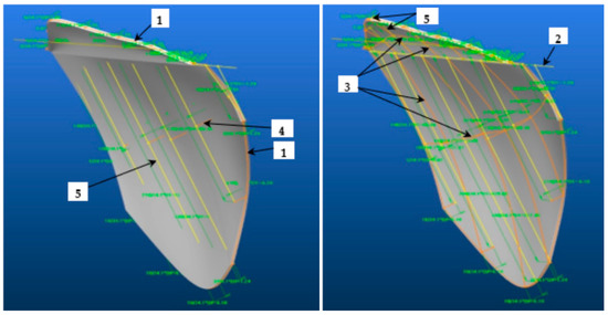
Figure 11.
The two views of the scapula with the supraspinous (1) and infraspinous fossa (2).
Each entity is defined by a network of curves in two main directions attached to the different contours to distinctly manage the supraspinous and infraspinous fossa. Each network is composed of orange lines (3) to describe the double curvature of the shape, some of which manage the depth of the concavity of the pit (4).
These orange lines (3) are connected to yellow lines (5) which manage the dimension of the contours parameterized by D1. The multiplicative coefficients assigned to the different dimensions parameterized by D1 made it possible to manage the morphology of the contours and therefore the morphology of the main parts of the scapula. The anatomy of the spine with the acromion process is a more complex 3D shape (Figure 12) which starts on the pivot line of the supraspinous and infraspinous fossae with a wide and shallow base surface (1) and ends with another slightly thicker and narrower base surface (2) specific to the acromion process. The morphology of the edges of this 3D shape, impacted by these starting and ending conditions, required the ends of the base surfaces to follow two 3D curves ((3): purple and orange curves). The purple and orange curves are connected respectively to a set of purple (4) and white (5) lines. Some (4) manage the global dimension of the 3D shape by the parameter D1, and others (5) manage the 3D wavy morphology. As stated previously, the morphology of this bone part is managed by the multiplicative coefficients assigned to the different dimensions parameterized by D1.
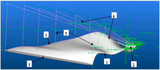
Figure 12.
The scapula spine with acromion process.
To obtain the curved shape of the coracoid process (Figure 13), a model used the main ribs, i.e., two types of purple lines which manage the dimension, and the morphology of the median curve of the 3D shape of the model. It is by D1 that the global dimension of the shape is managed and by the multiplicative coefficients of D1 that the 3D morphology of this element is managed.
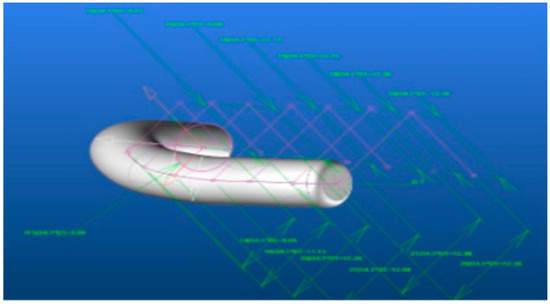
Figure 13.
The coracoid process.
3. Result and Discussions
3.1. 3D Modelling of Thorax without Any Scoliosis-Related Deformity
The developed model approximately represents the morphology of the thorax dimensionally, proportionally, and functionally. Figure 14 shows the developed thorax model under different views in standard spine condition, i.e., without any scoliosis-related deformities. This trunk model is controlled by the spine. In our previous results, the total length (Lt) of the spine was the only parameter to give the model for parameterizing the length (ltn) of each vertebra and disk (Table 1). In this notation, t represented the type of vertebra (C: cervical, D: dorsal, L: lumbar) and n represented the number of the vertebra in its category. Each vertebra was dimensioned by the parameter Dx (x: number of vertebrae out of category). Since the dimension of each bony part of the thorax was managed by this common parameter (Dx), the complete model of the thorax could then evolve in all three dimensions (3D) with each modification of the spine. To obtain the value of the spinal column parameters, an analysis of the images, in the frontal and coronal plane, of the patient’s spinal column X-rays was necessary. The first result was to test the limits of the model by imposing a perfect vertical rectilinear alignment of the spine. Under these conditions, it can verify the flexibility of the model’s adaptation to change its stature, i.e., the length of the spinal column. The passage of a spinal column length of Lt = 650 mm to Lt = 750 mm imposes length (ltn) values of each vertebra in Table 1: H650, H750.
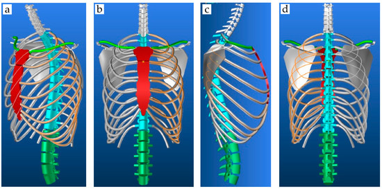
Figure 14.
The trunk model in the 3D view; (a) front view (b) back view (c) and right lateral view (d).

Table 1.
Values of Ltn for the different values of the deformation angles, Lt.
The test was carried out without any rotation in the three characteristic planes of the human being (Figure 15). The results showed a consistent increase in the length and volume of each bony part (spine and thorax). The other three tests were to show separately the deformation of the spinal column in the three characteristic planes: sagittal, coronal, and transverse. These deformations were carried out with the same length of the spinal column Lt = 650 mm.
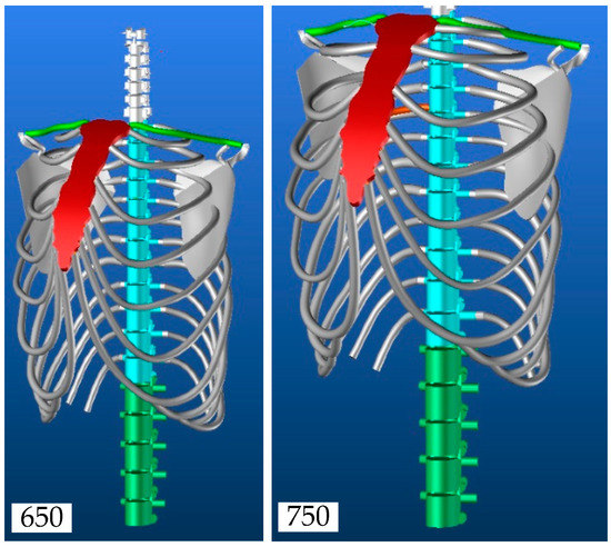
Figure 15.
The evolution of the thorax model.
Figure 16 presents the three deformations carried out independently from the angular data in Table 1. The first result was used as a reference to compare each of the deformations. Each image was taken in the deformation plane concerned to better appreciate the phenomenon in 3D view. An analysis of these initial results showed the need to know each of the initial parameters of the spine to have a realistic representation of the whole thorax.
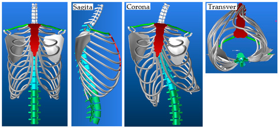
Figure 16.
Evolution of the thorax model in sagittal, coronal, and transverse planes.
Taken independently, the rotations led to unreal thorax deformation. The results showed that the shoulder blades were well located between the ribs R2 and R7 and they also showed the need to control them by adapting their position according to the deformity. Under certain conditions, one or both shoulder blades may pass through the ribs, which need to manage the relative position of the shoulder blades about the proximal ribs.
3.2. Scapula Anti-Penetration Management Model
Two angles, each associated with a marker centered on a pivot point Pc, made it possible to manage the two rotations of each scapula which contribute to the phenomenon of penetration of the scapula into the nearby ribs as shown in Figure 17. In this notation, r represents the type of rotation (1: axis1, 2: axis2) and c represents the scapula (L: left, R: right). To avoid the penetration of a scapula, the distance between the two points (C1, C2) defined on the ribs R4 and R7 to their respective projection (O1, O2) on the inner face of the scapula should be checked. In the evolution of the spine, the DCinitx distances of the points between those of the ribs and those of the shoulder blades, with x representing the index relative to the measurement points of the distances between the ribs and the shoulder blades (Figure 17), must be preserved as well as possible after deformation. The rotation that has the greatest impact on the phenomenon of penetration of the shoulder blades into the ribs is γCn in the transverse plane. To estimate the value of the Anglerc angles that avoid penetration, a series of tests were carried out with different values of rotation considering the gaps between each dorsal vertebra constant.
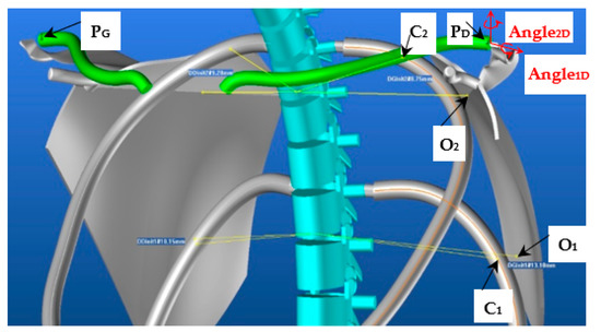
Figure 17.
The scapula orientation mark and control points.
Figure 18 represents the evolution curves of the different angles as a function of the corrections to be made to the DCinitx distances.
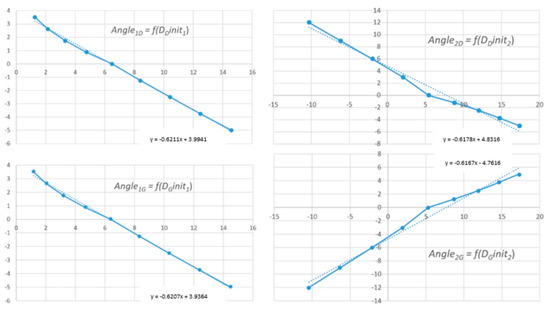
Figure 18.
Evolution curves of Angle1D, Angle2D, Angle1G and Angle2G in function of DDinit1, DDinit2, DGinit1 and DGinit2.
Figure 19 shows an example of a correction of the position of the shoulder blades during a rotation of the spine with a rotation δ = 1.5° between each vertebra. Figure 19a shows the initial state of our thorax model δ = 0° with an evolution of the vertebrae in the sagittal plane identical to Table 1 (sagittal, H650).
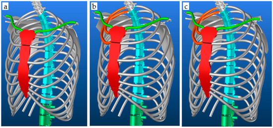
Figure 19.
The (a) initial spine position, (b) spine evolution of δ = 1.5° without correction, and (c) spine evolution of δ = 1.5° with correction.
3.3. 3D Modelling of Thorax with Scoliosis-Related Deformities
The measurements, relating to the patient’s skeleton, to reconstruct the adaptive thorax model were taken from the coronal and sagittal images from the EOS medical scanner. Figure 20a presents the measurements of each vertebra taken in the sagittal plane. Figure 20b–d shows the measurements of the cervical, dorsal, and lumbar vertebrae, respectively, in the coronal plane.
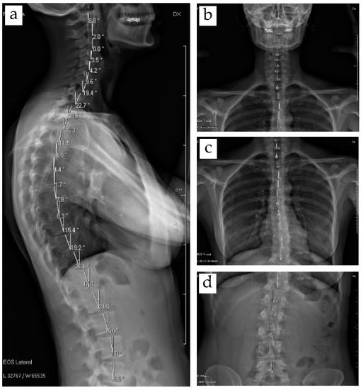
Figure 20.
The EOS medical images of (a) sagittal angles and (b–d) coronal angles.
Figure 21 shows the integration of the thorax model into the scanned body of a patient with mild scoliosis. Figure 21a shows that the overall volume of the model is well adjusted to the volume of the person. The spine follows the midline of the back perfectly. The sternum is very close to the front of the patient and follows the front midline correctly. Figure 21b shows that the orientation of the spine in the coronal plane is consistent with the course of Figure 20b–d.
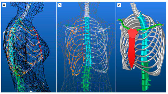
Figure 21.
The thorax model parametrized by measured data inside scanned patient body (a) the overall volume of the model, (b) orientation of the spine in the coronal plane and (c) 3D thorax model for the patient.
The dorsal ribs point to the right as they follow the orientation of the spine. They appear to be slightly offset from the contour of the scanned body. This can be explained by the fact that the patient did not take the same position when scanned by the body scanner and the EOS scanner. Each of the devices requires a specific position to be taken, which we can correct by detecting the exit of the model outside of the scanned body envelope. Figure 21c is a representation of our 3D thorax model for this patient which we will later use to define the position of the anthropometric points and morphological curves necessary for the design of his basic evolutionary pattern.
4. Conclusions
The current study presents a method to develop a fully parametric 3D adaptive model of the upper part of the human skeleton. The parameters make it possible to dimension the skeleton of the thorax and to adapt the morphology of the different bones that make it up. The modelling method is designed from the spine by following the deformation of the spine and makes it possible to adapt the global morphology of a patient suffering from strong scoliosis. The aim was to adapt the thorax skeleton according to the temporal evolution of the spinal column deformation. To do this, the images from the EOS medical scanner were used and processed to obtain the dimensional parameters of the vertebrae, as well as its angular positions at different planes. The EOS scan of the patient helps to control the global model of a patient. The integration of the model of the thorax, adjusted to the patient’s data in the body scan, enables the chain of acquisition, processing, and global model to be validated. It is always possible to improve the fit of the model from a morphological point of view for the different bones at the start of the integration. Later, it will only be necessary to modify the angles of the spine to see the evolution of the disease. Future work is planned to design a basic bodice adapted to the patient’s evolving morphology.
Author Contributions
Conceptualization, S.M., P.B., G.T. and M.A.A.; methodology, S.M., P.B., G.T. and M.A.A.; software, S.M., P.B. and M.A.A.; validation, P.B., G.T. and M.A.A., formal analysis, S.M. and M.A.A.; investigation, S.M., P.B., G.T. and M.A.A.; resources, P.B. and G.T., Y.X. and Y.C.; data curation, P.B., M.A.A., G.T., Y.X. and Y.C.; writing—original draft preparation, S.M., M.A.A. and P.B.; writing—review and editing, M.A.A. and P.B.; visualization, M.A.A., P.B. and G.T.; supervision, P.B., G.T. and Y.C.; project administration, P.B. and Y.C.; funding acquisition, P.B. and Y.X. All authors have read and agreed to the published version of the manuscript.
Funding
This research was funded by the European Erasmus Mundus Program, as part of the Sustainable Management and Design for Textiles (SMDTex) Project, grant number SMDTex-2017—6. The APC was supported by the National Natural science Foundation of China (NO. 51903183) and doctoral Funds of Education of China (NO. 2020M671577).
Institutional Review Board Statement
Not applicable.
Informed Consent Statement
Not applicable.
Data Availability Statement
The data presented in this study are available on request from the corresponding authors.
Acknowledgments
The authors would like to thank Lectra for the software.
Conflicts of Interest
The authors declare no conflict of interest.
References
- Yang, K.H.; Presley, B.R. Modeling the Thorax for Impact Scenarios; Elsevier Inc.: Amsterdam, The Netherlands, 2018; ISBN 9780128098325. [Google Scholar]
- Abtew, M.A.; Bruniaux, P.; Boussu, F. Development of adaptive bust for female soft body armour using three dimensional (3D) warp interlock fabrics: Three dimensional (3D) design process. IOP Conf. Ser. Mater. Sci. Eng. 2017, 254, 052001. [Google Scholar] [CrossRef]
- Abtew, M.A.; Bruniaux, P.; Boussu, F.; Loghin, C.; Cristian, I.; Chen, Y.; Wang, L. A systematic pattern generation system for manufacturing customized seamless multi-layer female soft body armour through dome-formation (moulding) techniques using 3D warp interlock fabrics. J. Manuf. Syst. 2018, 49, 61–74. [Google Scholar] [CrossRef]
- Abtew, M.A.; Bruniaux, P.; Boussu, F.; Loghin, C.; Cristian, I.; Chen, Y. Development of comfortable and well-fitted bra pattern for customized female soft body armor through 3D design process of adaptive bust on virtual mannequin. Comput. Ind. 2018, 100, 7–20. [Google Scholar] [CrossRef]
- Abtew, M.A.; Bruniaux, P.; Boussu, F.; Loghin, C.; Cristian, I.; Chen, Y.; Wang, L. Female seamless soft body armor pattern design system with innovative reverse engineering approaches. Int. J. Adv. Manuf. Technol. 2018, 98, 2271–2285. [Google Scholar] [CrossRef]
- Loring, S.H. Structural model of thorax and abdomen for respiratory mechanics. Math. Model. 1986, 7, 1083–1098. [Google Scholar] [CrossRef][Green Version]
- Beyer, B.; Sholukha, V.; Dugailly, P.M.; Rooze, M.; Moiseev, F.; Feipel, V.; Van Sint Jan, S. In vivo thorax 3D modelling from costovertebral joint complex kinematics. Clin. Biomech. 2014, 29, 434–438. [Google Scholar] [CrossRef]
- Fan, W.R.; Wang, H.X. 3D modelling of the human thorax for ventilation distribution measured through electrical impedance tomography. Meas. Sci. Technol. 2010, 21, 115801. [Google Scholar] [CrossRef]
- Perron, R.R.G.; Iskander, M.F. Dynamic 3D model of human thorax for the assessment of changes in lung fluid content and vital signs. In Proceedings of the 2016 IEEE/ACES International Conference on Wireless Information Technology and Systems (ICWITS) and Applied Computational Electromagnetics (ACES), Honolulu, HI, USA, 13–18 March 2016; pp. 16–17. [Google Scholar]
- Zhang, G.; Chen, X.; Ohgi, J.; Miura, T.; Nakamoto, A.; Matsumura, C.; Sugiura, S.; Hisada, T. Biomechanical simulation of thorax deformation using finite element approach. Biomed. Eng. Online 2016, 15, 1–18. [Google Scholar] [CrossRef]
- Saumarez, R.C. An analysis of possible movements of human upper rib cage. J. Appl. Physiol. 1985, 60, 678–689. [Google Scholar] [CrossRef]
- Dong, Z.; Jiang, G.; Wu, Z.; Cong, H. 3D parametric human modeling for warp-knitted seamless garment. Int. J. Cloth. Sci. Technol. 2015, 27, 532–548. [Google Scholar] [CrossRef]
- Chu, C.-H.; Tsai, Y.-T.; Wang, C.C.L.; Kwok, T.-H. Exemplar-based statistical model for semantic parametric design of human body. Comput. Ind. 2010, 61, 541–549. [Google Scholar] [CrossRef]
- Lin, Y.; Wang, M.J. Constructing 3D human model from front and side images. Expert Syst. Appl. 2012, 39, 5012–5018. [Google Scholar] [CrossRef]
- Wang, C.C.L. Parameterization and parametric design of mannequins. Comput. Des. 2005, 37, 83–98. [Google Scholar] [CrossRef]
- Mccartney, J.; Hinds, B.K.; Seow, B.L.; Gong, D. Dedicated 3D CAD for garment modelling. J. Mater. Process. 2000, 107, 31–36. [Google Scholar] [CrossRef]
- Cichocka, A.; Bruniaux, P.; Koncar, V. Modelling of Virtual Garment Design in 3D. Res. J. Text. Appar. 2007, 11, 55–63. [Google Scholar] [CrossRef]
- Cichocka, A.; Bruniaux, P.; Frydrych, I. 3D garment modelling—Conception of its structure in 3D. Fibres Text. East. Eur. 2016, 24, 121–128. [Google Scholar] [CrossRef]
- Antonela, C.; Viorica, C.; Laura, M.; Marian, P. Designing functional clothes for persons with locomotor disabilities. Autex Res. J. 2014, 14, 281–289. [Google Scholar]
- Shahani, M.; Steffek, V. Refashioning adaptive clothing for persons living with hemiparesis. In Proceedings of the 22nd Annual IFFTI Conference, Kent, OH, USA, 24–27 March 2020; pp. 1–11. [Google Scholar]
- Stjepanovič, Z.; Cupar, A.; Jevšnik, S.; Stjepanovič, T.K.; Rudolf, A. Construction of adapted garments for people with scoliosis using virtual prototyping and CASP method. Ind. Text. 2016, 67, 141–148. [Google Scholar]
- Seoud, L.; Adankon, M.M.; Labelle, H.; Dansereau, J.; Cheriet, F. Prediction of scoliosis curve type based on the analysis of trunk surface topography. In Proceedings of the 2010 IEEE International Symposium on Biomedical Imaging: From Nano to Macro, Rotterdam, The Netherlands, 14–17 April 2010; pp. 408–411. [Google Scholar]
- Bachmann, K.R.; Yaszay, B.; Bartley, C.E.; Bastrom, T.P.; Reighard, F.G.; Upasani, V.V.; Newton, P.O. A three-dimensional analysis of scoliosis progression in non-idiopathic scoliosis: Is it similar to adolescent idiopathic scoliosis? Child’s Nerv. Syst. 2019, 35, 1585–1590. [Google Scholar] [CrossRef]
- De Smet, A.; Tarlton, M.; Cook, L.; Berridge, A.; Asher, M. The top view for analysis of scoliosis progression. Radiology 1983, 147, 369–372. [Google Scholar] [CrossRef]
- Hong, Y.; Zeng, X.; Bruniaux, P.; Liu, K. Interactive virtual try-on based three-dimensional garment block design for disabled people of scoliosis type. Text. Res. J. 2016, 87, 1261–1274. [Google Scholar] [CrossRef]
- Hong, Y.; Bruniaux, P.; Zeng, X.; Liu, K.; Curteza, A.; Chen, Y.; Cedex, R. Visual-simulation-based personalized garment block design method for physically disabled people with scoliosis (PDPS). Autex Res. J. 2018, 18, 35–45. [Google Scholar] [CrossRef]
- Hong, Y.; Zeng, X.; Bruniaux, P.; Liu, K.; Chen, Y.; Zhang, X. Collaborative 3D-To-2D Tight-Fitting Garment Pattern Design Process for Scoliotic People. Fibres Text. East. Eur. 2017, 5, 113–117. [Google Scholar] [CrossRef]
- Mosleh, S.; Abtew, M.A.; Bruniaux, P.; Tartare, G.; Chen, Y. Developing an Adaptive 3D Vertebrae Model of Scoliosis Patients for applied sciences Developing an Adaptive 3D Vertebrae Model of Scoliosis Patients for Customize Garment Design. Appl. Sci. 2021, 11, 3171. [Google Scholar] [CrossRef]


Publisher’s Note: MDPI stays neutral with regard to jurisdictional claims in published maps and institutional affiliations. |
© 2021 by the authors. Licensee MDPI, Basel, Switzerland. This article is an open access article distributed under the terms and conditions of the Creative Commons Attribution (CC BY) license (https://creativecommons.org/licenses/by/4.0/).