Abstract
Introduction: This study describes the theoretical foundations of the development of an equation that allows for the estimation of the mobilized load when training with suspension devices (type TRX®) and presents a mobile application as a means for its use. Methods: Systems of equations are proposed of which the terms depend on the angulation of the device with respect to the vertical (angle α), the relationship between the height of grip, the height of the center of mass and the weight of the subject, which are recorded from a photo. Results: Based on the photo and the subject’s standing height, the application allows the user to measure the angle α, providing the values of applied force (in N) and mobilized load in relation to the percentage of body mass, applying the calculations described in our equations. The equation also provides the estimated value of the load mobilized during a push up on the floor (68% of the subject’s body mass) and the equation for the calculation of the mobilized load when the suspension device is fixed to the feet. Conclusions: It is possible to use equations to estimate the load mobilized in each repetition during training using suspension devices and to implement this algorithm in a mobile application.
1. Introduction
In recent years, different mobile applications (apps) have been developed to quantify, store or organize training parameters using sensors integrated in a Smartphone (GPS, gyroscopes, camera, accelerometers, etc.) without the need for other external devices (wearables). The data provided directly from the sensors can be used by the apps to calculate kinematic parameters. These parameters, when suitably presented, can constitute an important source of information for users.
These apps are increasingly accepted by the professional and scientific community, to the point of becoming valid alternatives to more expensive equipment used to date to perform biomechanical measurements. For example, My Jump 2® [1] and Kinematic lab jump® [2], use video analysis to provide the flight time of a vertical jump, which allows its height to be determined. Other apps, such as Runtastic® [3] or Endomondo® [4], use GPS to provide speed and position values. Accelerometers and gyroscopes integrated into phones are also used by certain apps, like Dorsiflex® [5], to measure joint range of motion.
Although the range of available applications covers a wide spectrum of physiological, kinanthropometric and fitness parameters, an app that estimates the load mobilized during a repetition of suspension training has not been developed to date. The benefit of an app that estimates the load mobilized during this type of activity lies in the popularity acquired in recent years by the TRX® system (Fitness Anywhere LLC, San Francisco, CA, USA) and other similar devices. These tools are made of inextensible straps that allow the user to grip or attach him-/herself to one of the ends, while the other one remains anchored to a fixed structure, in order to perform resistance training in suspension or by traction.
Portability, versatility and the possibility of varying the load through changes in body position or grip have made these devices a popular means of training among different populations. To use this training element, one of the ends of the tape is fixed securely to a structural anchor (trellis, door frame, wall, training frame, etc.), while the free end is grasped by the subject, who performs the exercise by mobilizing a proportion of his/her body weight on a point of support. The wide variety of available exercises means that the free end of the strap can also be placed around one foot or both feet, thus moving the load to the arms, which perform the exercise, supported by the ground. The problem that arises during the use of these training systems, at least initially, is that the load that is mobilized in each repetition is difficult to estimate in real time. This is an important limitation for adequate exercise prescription, given that the subject works with a percentage of his/her own body mass that varies depending on the inclination of the body [6,7].
There are different procedures for estimating the load of suspension training. Surface electromyography (EMG) has been the most used method by researchers to quantify the load [8,9,10]. Others have used forces recorded by dynamometers and force platforms from the inclination of the body with respect to the ground and other postural considerations of execution [6,7,8,9]. In other cases, the number of repetitions and the indication of a percentage of maximum heart rate during exercise have been used as a means for estimating the load [6,11,12].
The training objectives when exercising with suspension devices are varied and can include strength development, balance, flexibility, abdominal and postural stability [13]. Additionally, the results obtained through their use either independently or in comparison with other types of exercise have proven to be similar [6,10,14,15,16].
The subject perceives that a greater degree of inclination implies a greater effort, but he/she cannot quantify the amount of body weight moved. One proposal is to estimate the load based on the level of difficulty, taking as a reference the body’s position on a mat on which levels are defined, ranging from easy to hard [17]. Other authors propose equations based on the recording of measurements of the different forces involved in the execution, considering the inclination of the body with respect to the ground and the point of support [7,18,19,20]. Finally, others also provide angular references and their relation to the load in each phase of the exercise [21].
Therefore, to address the issue of quantifying the training load in suspension quickly and cheaply, we propose the use of equations in a mobile application to estimate the muscular force applied in each repetition.
2. Objective
The main objective of this technical note is to present a system for estimating the load mobilized during exercise in suspension training using a mobile application created for this purpose (Kinematic Lab susp®).
As a secondary objective, we have developed the theoretical foundations for the equations proposed to estimate the force developed by the subject.
3. Methods
Operation of the App
The Kinematic Lab Susp® mobile application was developed to estimate the load that is mobilized during each repetition in tensile or suspension exercises. The app records the initial angle of work, formed by the vertical projection of the fixed end to the structure and the tape of the device.
The present study is a strictly theoretical proposal for the calculation of the mobilized body weight during suspension training, which has not had an experimental group of study subjects. To verify the coherence of our calculations, we have used the work of Melrose and Dawes [7], which proposes regression equations to estimate the percentage of mobilized body weight depending on the angle of inclination of the subject with respect to the vertical.
To collect the measurements, a photograph must be taken perpendicular to the plane of execution of the movement, in which the anchor point of the TRX® can be located to a fixed structure (this point must be marked by the user of the application on the photograph). From this photograph, the application will draw a vertical line that constitutes one of the arms of the angle of interest (α). The other arm of the angle α corresponds to the path that the tape follows from the anchor to the gripping point of the subject performing the exercise. Therefore, the second mark the user makes on the photograph must be at some point on the tape itself, so that α is defined by the vertical projection of the anchor and the TRX® tape. Prior to the inputting of this information, the application requires a set of data on the subject performing the action, which is used to estimate the mobilized load: the height at which the TRX® is gripped (head, chest or abdomen), the subject’s height (in m) and their body mass (in kg).
At the time of taking the photograph and during the execution of the exercise, there are two mandatory conditions: (i) the subject maintains an angle of 90° between the body axis and the TRX® tape, and (ii) the tape maintains its tension so that its trajectory is straight at all times.
4. Equation Proposal
The base calculation solves a static problem which must take into account the disposition of the elements of the system with their respective angles, and the different forces involved.
The initial composition of the angles are represented in Figure 1.
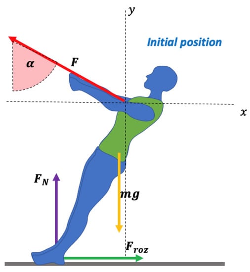
Figure 1.
Initial position and reference angles for the calculation.
It is important to make reference to the relationships between the angles to be able to perform the calculations and properly locate the forces. Note, for example, that to have a clear reference of the value of the angle (β) the position of the arms with respect to the trunk must form an angle of 90°. The forces of this system are represented in Figure 2:
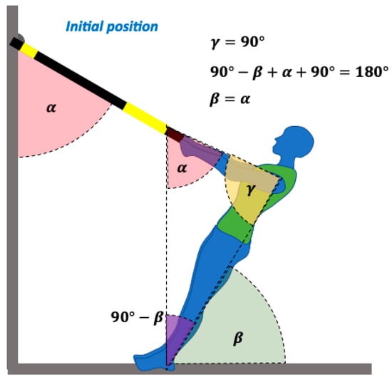
Figure 2.
Representation of the forces involved in the system.
Once the forces have been located and represented, the condition of equilibrium is imposed for the calculation, that is, the sum of all the forces and moments at the initial time of the movement is 0 .
Separating the forces into their components and determining the systems of equations, the result would be:
The system pivots on the ground, just above the point of support of the feet. There are two forces that generate moment (M); one is the force (F) and the other is the component y of the weight (mg).
In the case of an exercise in which the suspension system is at chest height, is the distance between the ground and an average distance between the shoulders and the chest (76.5% of the height) and is the distance from the center of gravity to the ground (56% of the height). Anthropometric tables of corporal proportionality in adults have been used for the determination of these distances necessary for the calculation [22].
Based on these equations, and knowing the mass (in kg) and height (in m) of the subject and the angle α (in degrees), the value of our unknown quantity (F) is obtained by solving for F in the moment equation (M):
If the value of F (in N) is divided by g the result is expressed in kiloponds (kp), which corresponds to the value in kg.
Given the great variety of exercises that can be performed with suspension systems and the influence of the height of the grip on the mobilized load, Kinematic lab susp makes it possible to choose the position from which muscle strength starts to be exerted from four options, using a different algorithm for each position (Figure 3):
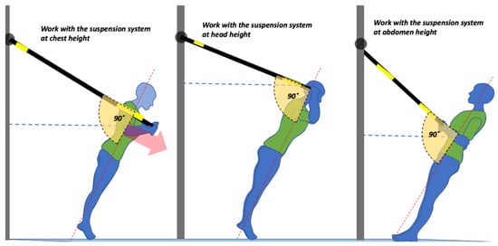
Figure 3.
Different options for exercise positions.
- -
- Exercises in which the system is at the level of the head, in which case of the subject’s height.
- -
- Exercises in which the system is at chest level, in which case of the subject’s height.
- -
- Exercises in which the system is at the level of the abdomen in which case of the subject’s height.
- -
- Exercises in which the subject is suspended by the feet and supported by their hands on the floor, in which case of the subject’s height and
The values of the distances and have been determined through body proportionality data obtained from the literature and simplified for the calculation [22].
Figure 3 shows the different options for exercise positions. Training options should include the support position of the hands on the ground (shown in Figure 5).
It should be borne in mind that the orientation of the subject (with his/her front or back to the anchor point of the suspension system) does not affect the load to be mobilized, but rather the muscles that are recruited to mobilize the load effectively. It is not the same to pull the suspension system towards the chest, where the agonist muscles are the interscapular and other dorsal muscles, as it is to push on the suspension system, in which case the agonists are the pectoral and elbow extensor muscles. In both cases the load to be mobilized is the same, but this aspect is important because it can affect the perception of intensity.
5. Results
An algorithm was developed for the calculation from Equation (4), through which the mobile application provides the estimation of the load that is mobilized from the initial position.
For this, the operator must provide information on the initial grip position (out of four options), the subject’s height and body mass. Then, the subject must provide the photograph for determination of the working angle (α). Next, the application calculates the results for different working angles (between 10° and 55° with respect to the vertical) and different grip positions for the same subject of mass 60 kg and 1.60 m in height, in relation to % body weight mobilized in each repetition (Table 1 and Figure 4).

Table 1.
Weight distribution according to working angles and grip positions. Data are for the same subject of mass 60 kg and 1.60 m in height, and expressed as the percentage of body weight mobilized in each repetition.
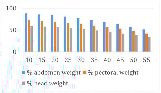
Figure 4.
Percentage of load depending on the angle and height of the grip.
The data indicate that as the working angle (α) increases, the initial load to be mobilized by the subject decreases and that the position of the initial grip with respect to body height also influences the mobilized load value. With the provided corporal proportionality references, working with a grip at the height of the abdomen implies an increase in the initial load to be mobilized of between 9% and 17%, depending on the angle of work with respect to the work done with the grip at chest height. In addition, a grip at abdomen height implies between 17% and 30% compared to a grip at head height. Therefore the highest loads are mobilized working with the grip at the level of the abdomen. It must be considered that the intensity perception of an exercise can be more related to the abilities of the involved muscles to generate force than with the value of the absolute load mobilized during the execution.
Data from the present technical note indicate good agreement (r = −0.99) with those provided by the equations proposed by Melrose and Dawes [7] for values of 30°, 45°, 60° and 75° (Table 2), taking into account that these authors measured the angle formed by the inclination of the body with respect to the vertical, which is the complementary angle to that recorded with Kinematic Lab Susp.
Table 2.
Correspondence between the mobilized weight when considering different angles and their complementary ones (based on the equation of Melrose and Dawes [7]).
6. Other Proposals for Calculation
If the subject exercises suspended by their ankles (Figure 5), the force supported on the arms can be calculated in the following way (Equation (5)):
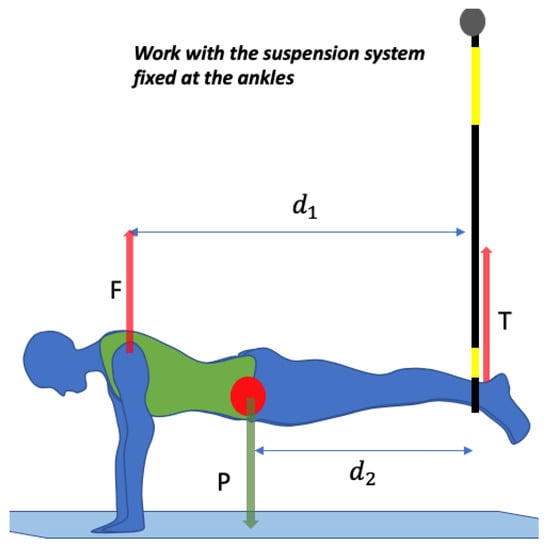
Figure 5.
Force system when the subject is suspended by the ankles.
Again, the equilibrium condition, in which the sum of forces and moments must be 0, is imposed:
The distances and the mass are known, so that by solving for F the following is left:
To obtain the equivalent value in kg the value of F can be divided by g, to obtain kp.
This value could approximate the load value that the subject supports in the initial position of a push-up on the arms with an arms–trunk angle of ±30°, which in this case would be 68% of body weight, very similar to the value reported in the literature [12,23].
If the feet are at an angle with respect to the horizontal, the calculation is more complicated due to having to consider the components of some of the forces that appear and the value of the coefficients of friction at the contact points. For small values of α, the force necessary to maintain the weight of the subject in these situations can be approximated by the equation:
In the previous equation, after discarding the components of the forces and frictions, there is no term that depends on the angle α, although intuition and experience tell us that by varying the inclination of the feet with respect to the point of support, the necessary force varies, so the dependence on the angle seems clear.
If all the forces and their components are considered, these dependencies on α appear in the equations. Although Kinematic Lab Susp does not perform this calculation, we propose the following systems of equations for this estimation:
The conditions of equilibrium impose that the sum of forces and moments is 0:
where is the sum of the forces applied by the subject at the points of contact with the ground (in N), m the mass of the subject (in kg), a acceleration and is the sum of the moments generated by the forces, dependent on their moment of inertia (I) and the angular acceleration (α).
There are four forces that generate moment: the weight (P), the normal force , the friction force and the component of the force on the x axis . This is represented in Figure 6.
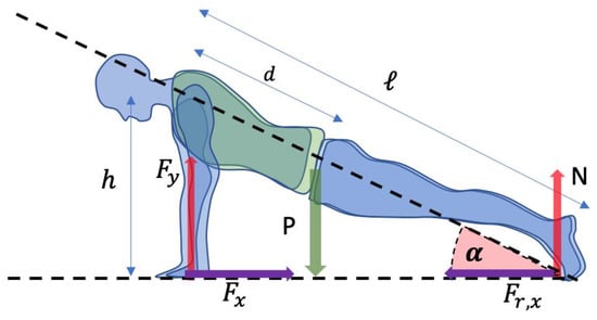
Figure 6.
Force system in the push up position.
Our unknown is , which corresponds to the force necessary to maintain the corresponding part of the subject’s weight. To arrive at we propose a system of equations that can be expressed as follows:
Equations for forces in x and y:
Equation for moments (M):
Substituting and applying trigonometry in the moment equation, the three equations become:
We solve for in the first equation and we substitute the value of N in the 2nd and 3rd equations:
Solving for in this last equation and simplifying the terms we have left:
If we recover the equation of the forces in the y-axis and we insert the new known values, when we solve for (which is really our unknown), we obtain:
In view of this last equation (Equation (6)), it seems clear that the angle formed by the trunk with the horizontal affects the force to be developed by the arms, as indicated by the terms with sines and cosines. If we go to an extreme case, for example, an inverted arm support, so that the angulation of the trunk is 90° with respect to the horizontal, and we substitute the corresponding value of the sine and the cosine we see that the force that the subject must exert is:
That is, their own weight, which gives coherence to our calculation.
7. Discussion and Conclusions
The proposed equations in this technical note are a first approach toward quantifying the load mobilized during suspended exercise. In this first step, we focused on verifying the validity of our equations with data from a previous work. Further studies are warranted to verify these calculations in experimental contexts.
It is possible to theoretically estimate the load mobilized during training with suspension devices by determining the angle that the belt of the training device forms with the vertical and the height of the grip in relation to the subject performing the action. These data show an almost perfect agreement with those obtained experimentally in the literature [7]. The equations that allow these calculations and how they have been implemented in the development of a mobile application are presented. Secondarily, this technical note proposes another equation which can be used to estimate the load mobilized by a subject during a pushup based on his/her weight and height.
Author Contributions
Introduction and conceptualization, I.L.-M. and L.M.A.; proposal of objectives and development of equations, V.P.P. and I.L.-M.; data analysis and review, I.L.-M., L.M.A. and P.M.-C.; writing, I.L.-M. and L.M.A.; original idea, I.L.-M. and P.M.-C.; revision and corrections, I.A., L.M.A. Writing—Review and editing, I.L.-M., L.M.A. and P.M.-C.; supervision, I.A. and V.P.P. All authors have read and agreed to the published version of the manuscript.
Funding
This research received no external funding.
Institutional Review Board Statement
Not applicable.
Informed Consent Statement
Not applicable.
Data Availability Statement
Data is contained within the article.
Conflicts of Interest
The authors declare that they have no conflict of interest.
References
- Balsalobre, C. My Jump 2 (Version 5.0.9) [Apple iOS Application]. 2016. Available online: http://apps.apple.com/es/app/my-jump-2/id1148617550 (accessed on 20 May 2020).
- López-Moranchel Maurelos, P. Kinematic Lab Jump (Version 1.1.2) [Apple iOS Application]. 2019. Available online: https://apps.apple.com/es/app/kinematic-lab-susp/id1445690413 (accessed on 20 May 2019).
- Runtastic GmbH. Adidas Running by Runtastic (Version 11.2) [Apple iOS Application]. 2019. Available online: https://apps.apple.com/es/app/adidas-running-by-runtastic/id336599882 (accessed on 20 May 2020).
- Endomondo.com. Endomondo Sports Tracker (Version 18.10.1) [Apple iOS Application]. 2018. Available online: http://apps.apple.com/es/app/endomondo-sports-tracker/id333210180 (accessed on 20 May 2020).
- Balsalobre, C. Dorsiflex (Version 3.0.1) [Apple iOS application]. 2017. Available online: http://apple.com/lv/app/dorsiflex/id1315394326 (accessed on 20 May 2020).
- Giancotti, G.; Fusco, A.; Iannaccone, A.; Cortis, C. Short-Term Effects of Suspension Training on Strength and Power Performances. J. Funct. Morphol. Kinesiol. 2018, 3, 51. [Google Scholar] [CrossRef]
- Melrose, D.; Dawes, J. Resistance Characteristics of the TRX™ Suspension Training System at Different Angles and Distances from the Hanging Point. J. Athl. Enhanc. 2015, 4, 2–5. [Google Scholar]
- Borreani, S.; Calatayud, J.; Colado, J.C.; Moya-Nájera, D.; Triplett, N.T.; Martin, F. Muscle activation during push-ups performed under stable and unstable conditions. J. Exerc. Sci. Fit. 2015, 13, 94–98. [Google Scholar] [CrossRef]
- Fong, S.S.; Tam, Y.T.; Macfarlane, D.J.; Ng, S.S.; Bae, Y.H.; Chan, E.W.; Guo, X. Core Muscle Activity during TRX Suspension Exercises with and without Kinesiology Taping in Adults with Chronic Low Back Pain: Implications for Rehabilitation. J. Evid. Based Complementary Altern. Med. 2015, 2015, 910168. [Google Scholar] [CrossRef]
- Harris, S.; Ruffin, E.; Brewer, W.; Ortiz, A. Muscle activation patterns during suspension training exercises. Int. J. Sports Phys. Ther. 2017, 12, 42–52. [Google Scholar] [CrossRef] [PubMed]
- Jiménez-García, J.D.; Hita-Contreras, F.; de la Torre-Cruz, M.; Fábrega-Cuadros, R.; Aibar-Almazán, A.; Cruz-Díaz, D.; Martínez-Amat, A. Risk of Falls in Healthy Older Adults: Benefits of High-Intensity Interval Training Using Lower Body Suspension Exercises. J. Aging. Phys. Act. 2019, 27, 325–333. [Google Scholar] [CrossRef]
- Jiménez-García, J.D.; Martínez-Amat, A.; De la Torre-Cruz, M.J.; Fábrega-Cuadros, R.; Cruz-Díaz, D.; Aibar-Almazán, A.; Achalandabaso-Ochoa, A.; Hita-Contreras, F. Suspension Training HIIT Improves Gait Speed, Strength and Quality of Life in Older Adults. Int. J. Sports Med. 2019, 40, 116–124. [Google Scholar] [CrossRef] [PubMed]
- Bettendorf, B. TRX® Suspension Training® Bodyweight Exercise: Scientific Foundations and Practical Applications. 2010. Available online: https://www.sportsrehabexpert.com/TRX%20White%20Paper.pdf (accessed on 25 May 2020).
- Smith, L.; Snow, J.; Fargo, J.; Buchanan, C.; Dalleck, L. The Acute and Chronic Health Benefits of TRX Suspension Training® in Healthy Adults. Int. J. Res. Ex. Phys. 2016, 11, 1–15. [Google Scholar]
- Tinto, A.; Campanella, M.; Fasano, M. Core strengthening and synchronized swimming: TRX® suspension training in young female athletes. J. Phys. Fit. Sports Med. 2017, 57, 744. [Google Scholar] [CrossRef]
- Maté-Muñoz, J.L.; Monroy, A.J.A.; Jodra Jiménez, P.; Garnacho-Castaño, M.V. Effects of instability versus traditional resistance training on strength, power and velocity in untrained men. J. Sports Sci. Med. 2014, 13, 460–468. [Google Scholar] [PubMed]
- Gaedtke, A.; Morat, T. TRX Suspension Training: A New Functional Training Approach for Older Adults—Development, Training Control and Feasibility. Int. J. Exerc. Sci. 2015, 8, 224–233. [Google Scholar] [PubMed]
- Campa, F.; Silva, A.; Toselli, S. Changes in Phase Angle and Handgrip Strength Induced by Suspension Training in Older Women. Int. J. Sports Med. 2018, 39, 442–449. [Google Scholar] [CrossRef]
- Giancotti, G.F.; Fusco, A.; Varalda, C.; Capelli, G.; Cortis, C. Evaluation of Training Load during Suspension Exercise. J. Strength Cond. Res. 2019. [Google Scholar] [CrossRef]
- Giancotti, G.F.; Fusco, A.; Varalda, C.; Capranica, L.; Cortis, C. Biomechanical Analysis of Suspension Training Push-Up. J. Strength Cond. Res. 2018, 32, 602–609. [Google Scholar] [CrossRef]
- Gulmez, I. Effects of Angle Variations in Suspension Push-up Exercise. J. Strength Cond. Res. 2017, 31, 1017–1023. [Google Scholar] [CrossRef]
- Dreyfus, H. The Measure of Man. Human Factors in Design; John Wiley & Sons: New York, NY, USA, 2002. [Google Scholar]
- Suprak, D.N.; Dawes, J.; Stephenson, M.D. The Effect of Position on the Percentage of Body Mass Supported During Traditional and Modified Push-up Variants. J. Strength Cond. Res. 2011, 25, 497–503. [Google Scholar] [CrossRef] [PubMed]
Publisher’s Note: MDPI stays neutral with regard to jurisdictional claims in published maps and institutional affiliations. |
© 2020 by the authors. Licensee MDPI, Basel, Switzerland. This article is an open access article distributed under the terms and conditions of the Creative Commons Attribution (CC BY) license (http://creativecommons.org/licenses/by/4.0/).