A High Gain DC-DC Converter with Grey Wolf Optimizer Based MPPT Algorithm for PV Fed BLDC Motor Drive


 ,
,  and
and 
Abstract
1. Introduction
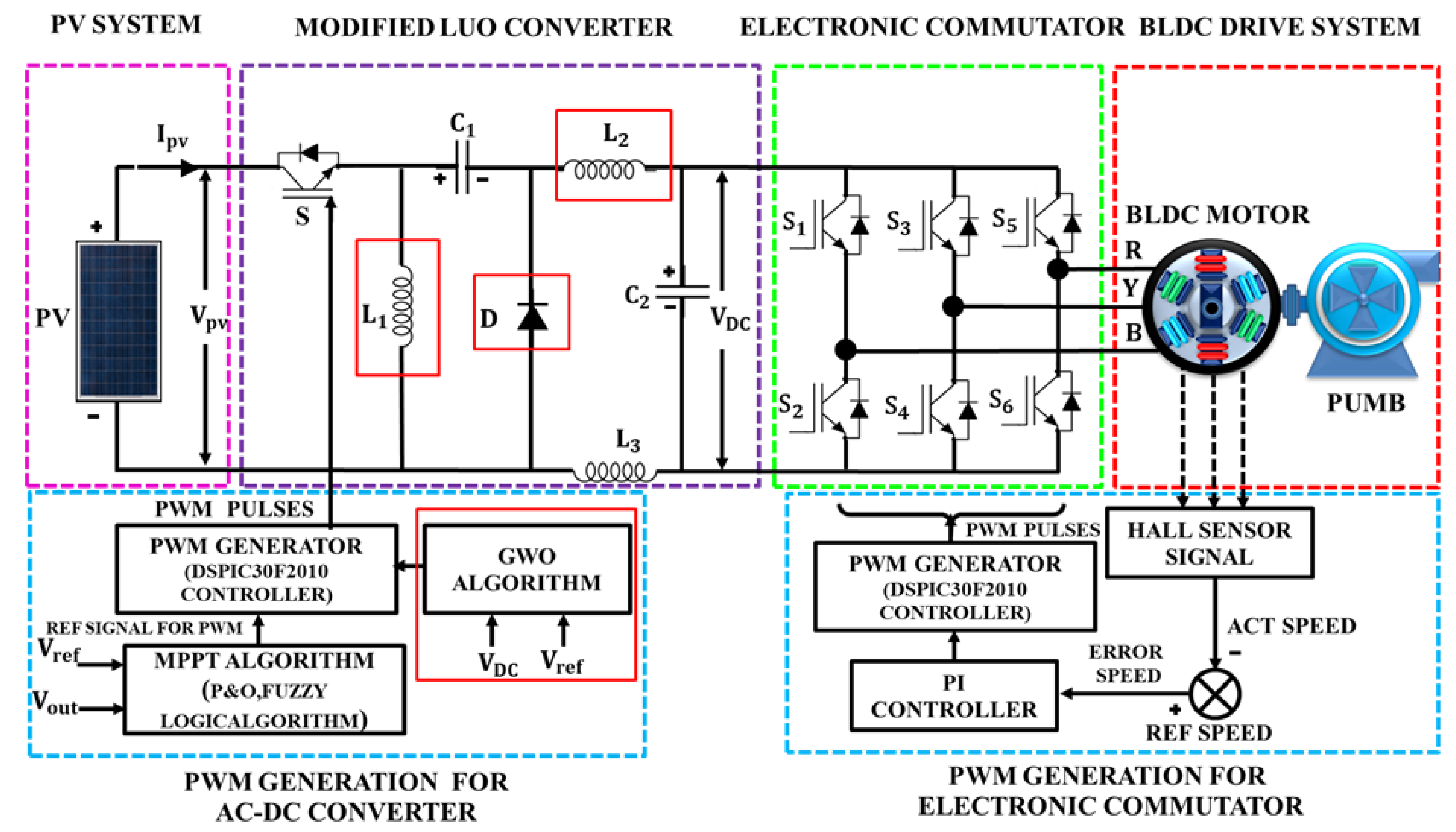
2. Systematic Working of the Proposed System
3. Proposed System Design
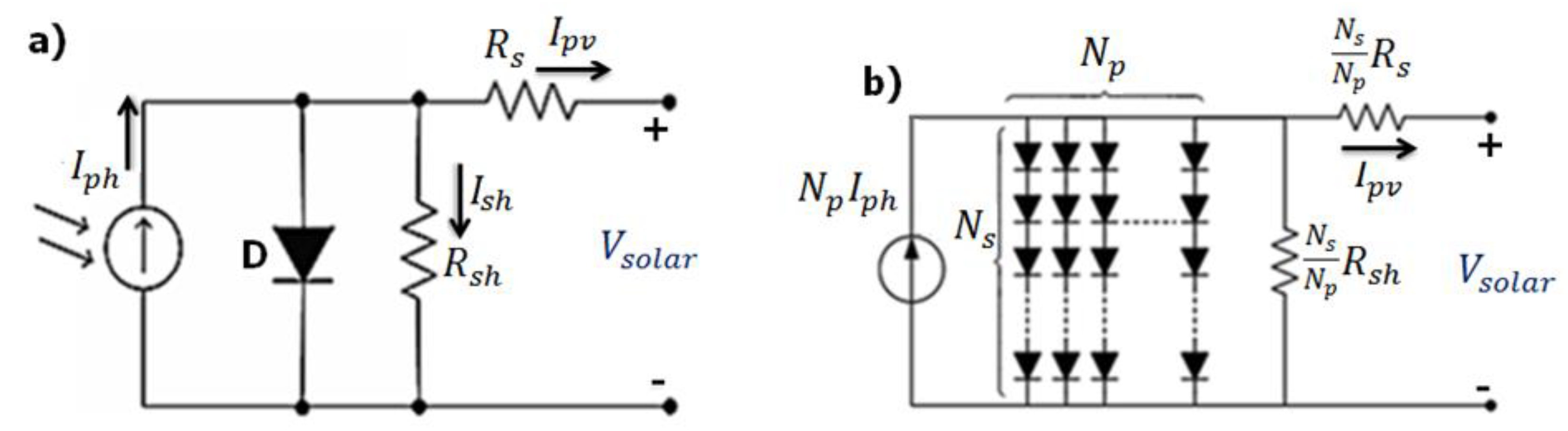
3.1. Modelling of the Solar Cell
3.2. Design of the Proposed System
3.3. Modelling of DC-Link Capacitor
3.4. Water Pump Design
3.5. BLDC Motor Controlled by Electronic Commutation
4. Maximum Power Point Tracking (MPPT) Algorithm
4.1. P&O Algorithm
4.2. FUZZY Algorithm
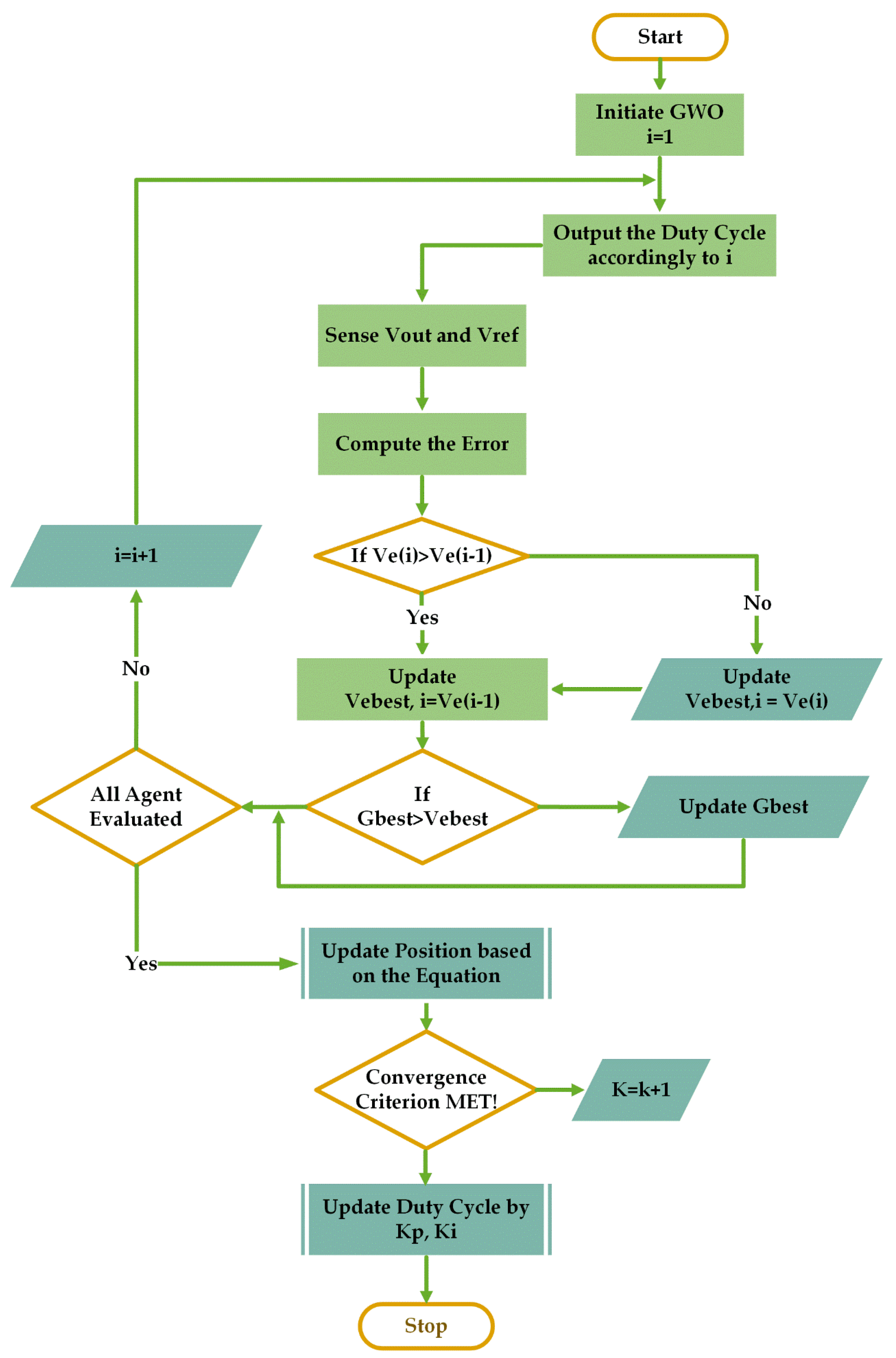
4.3. GWO Algorithm
5. Simulation and Experimental Results of the Proposed System
5.1. Simulation Results
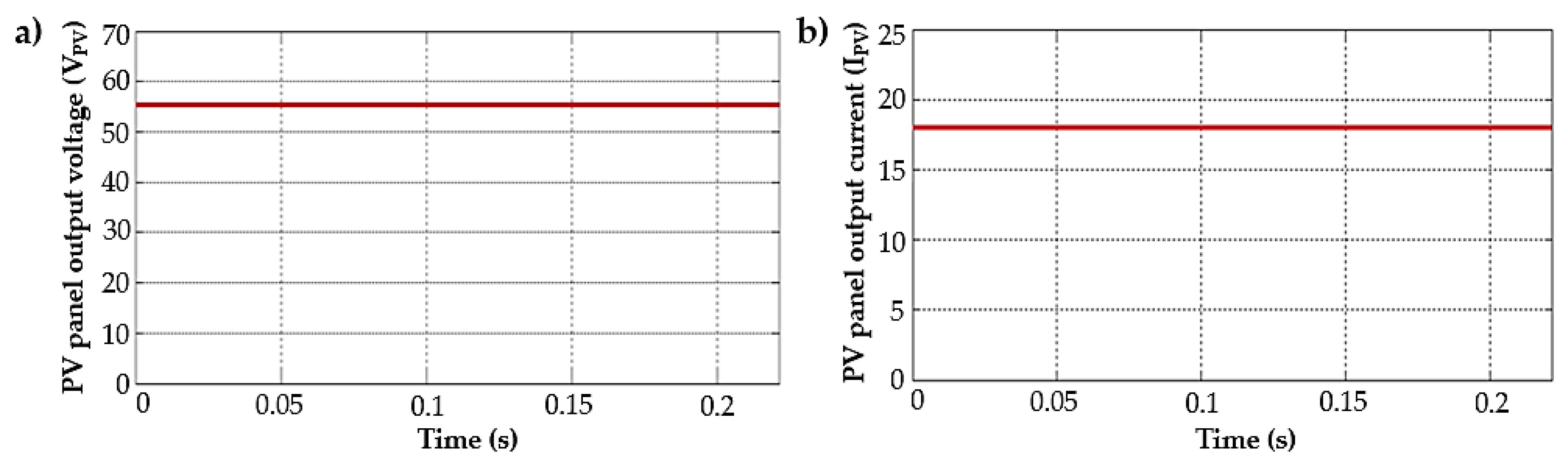
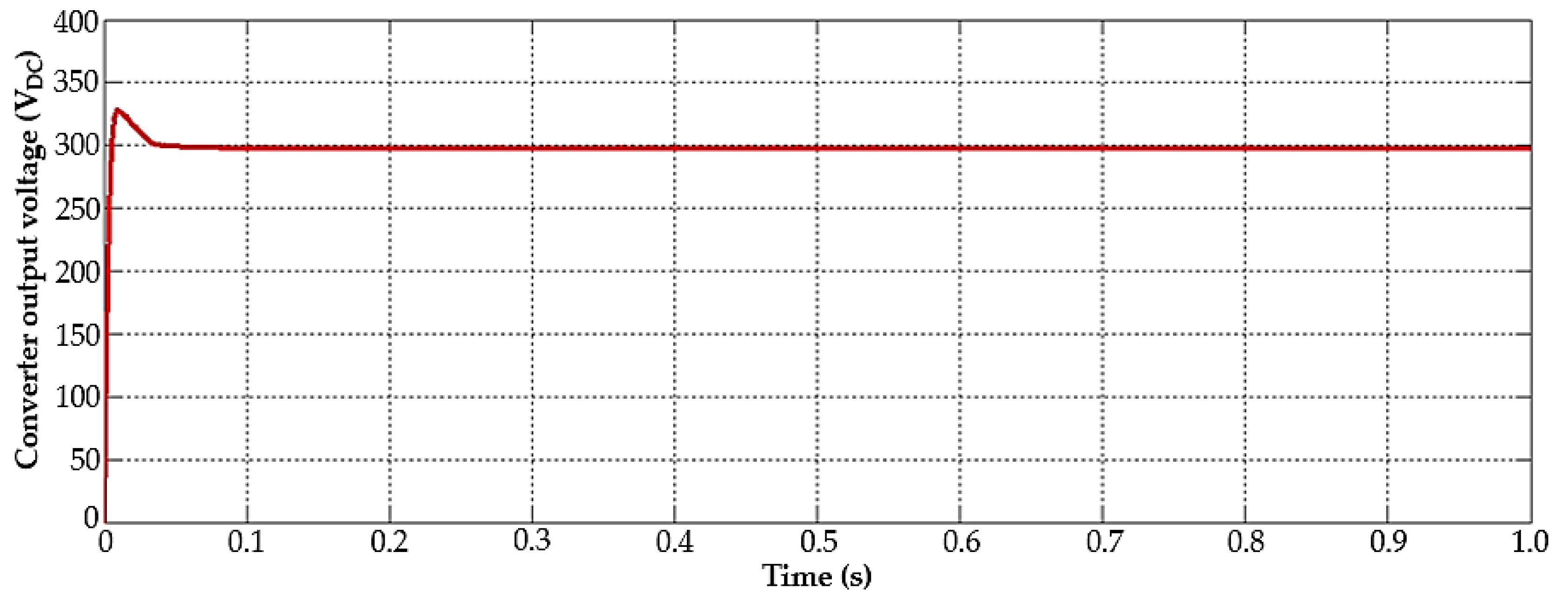
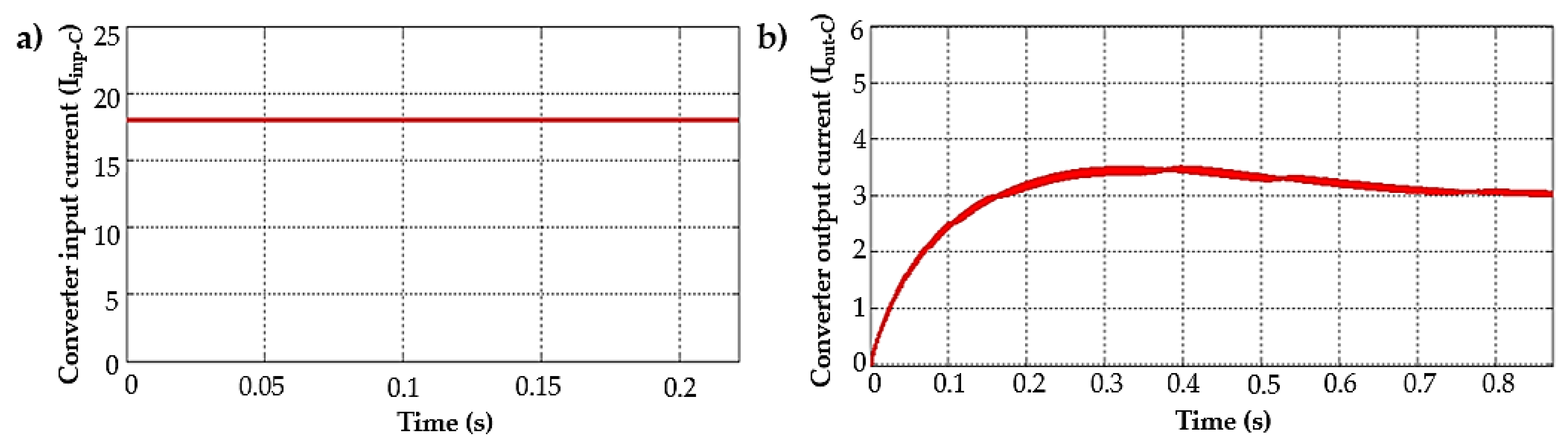
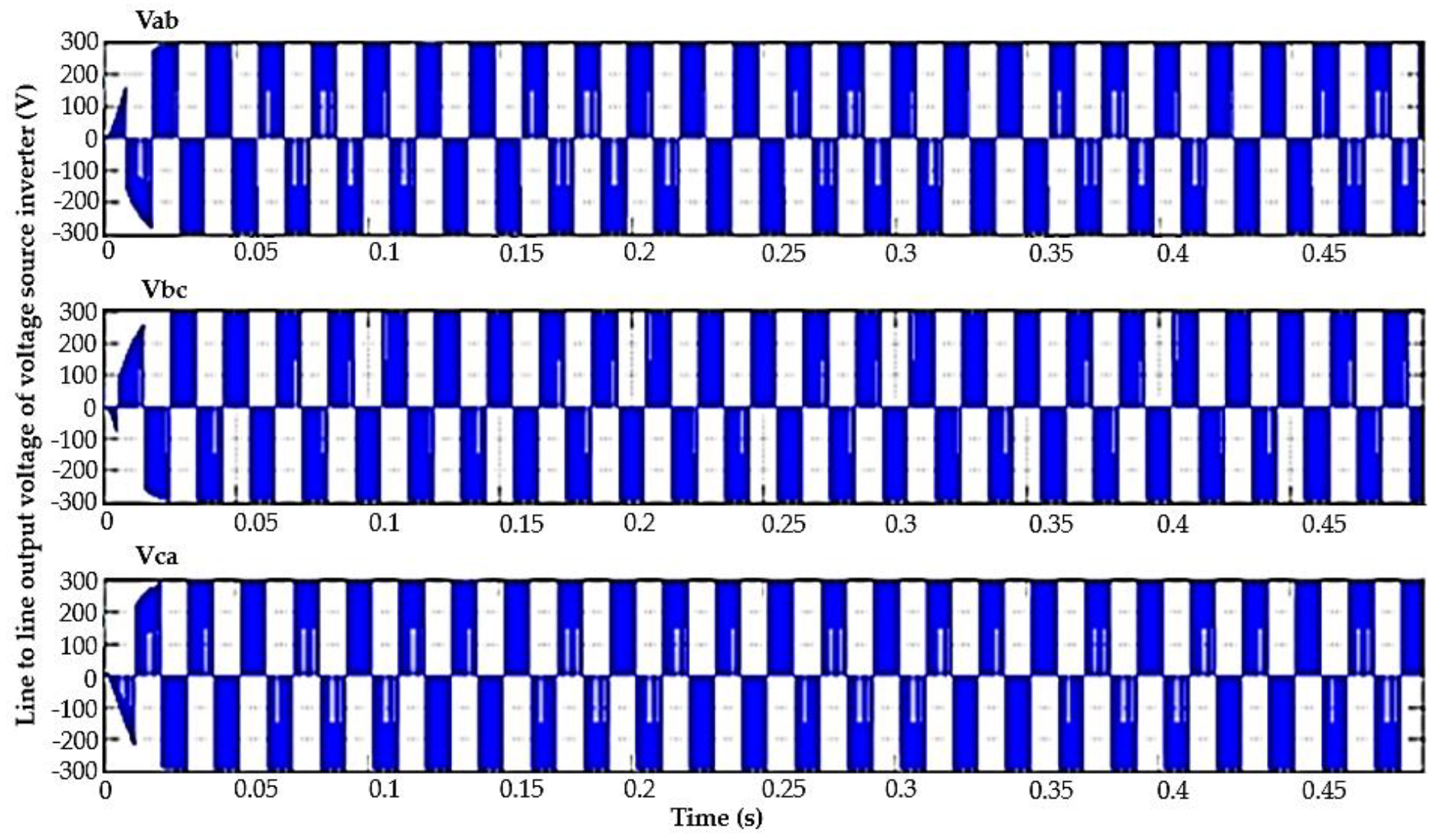
5.1.1. Performance of the Converter
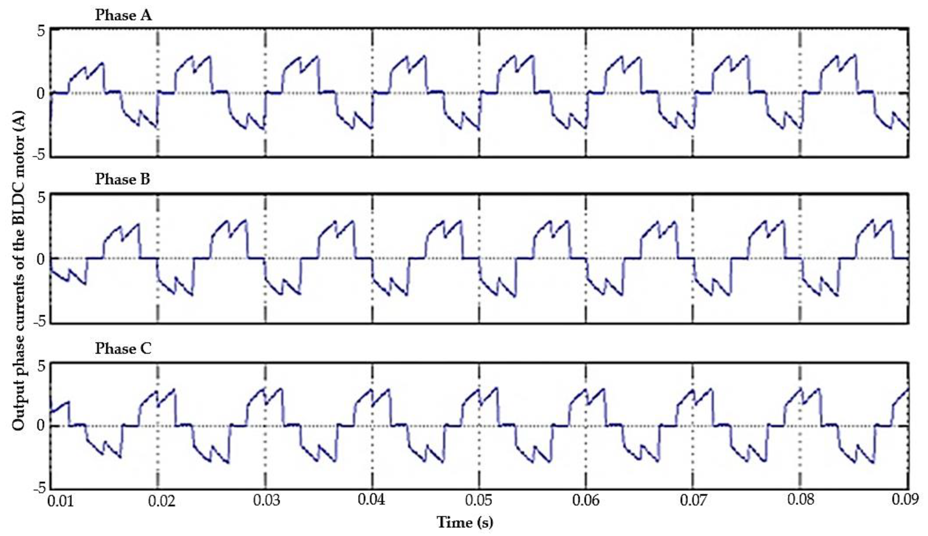
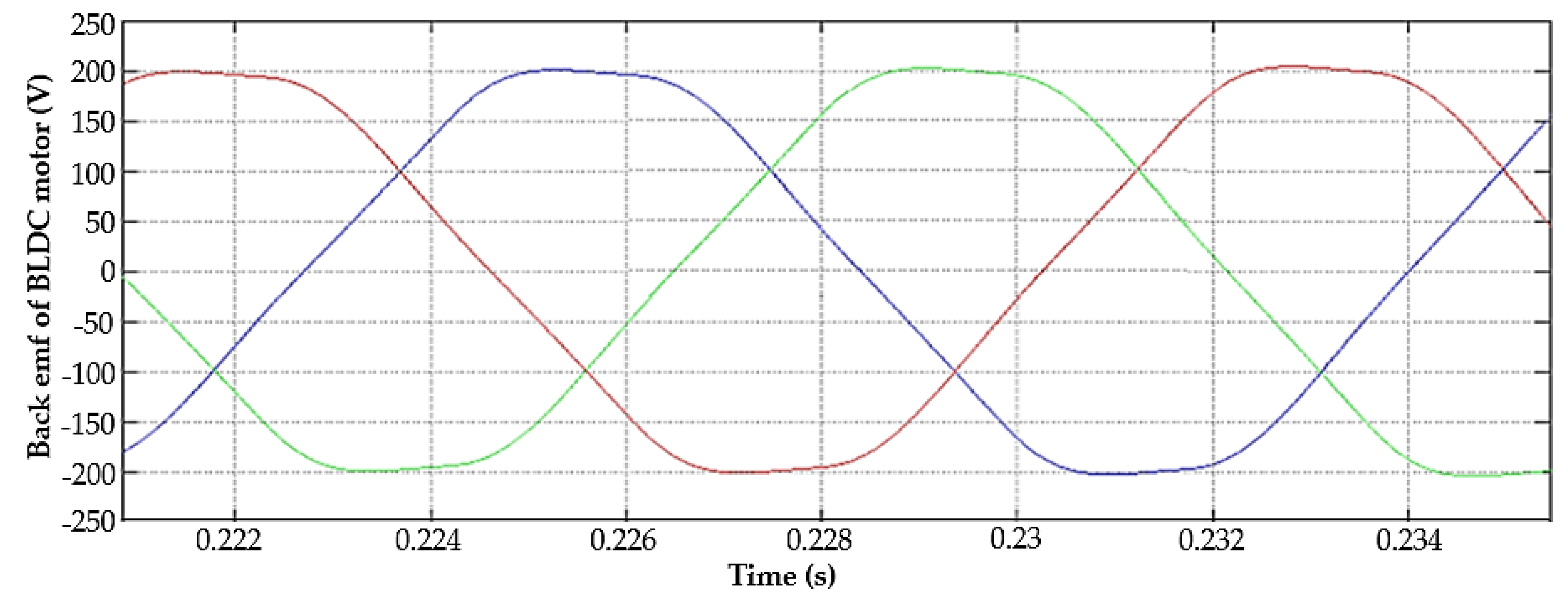
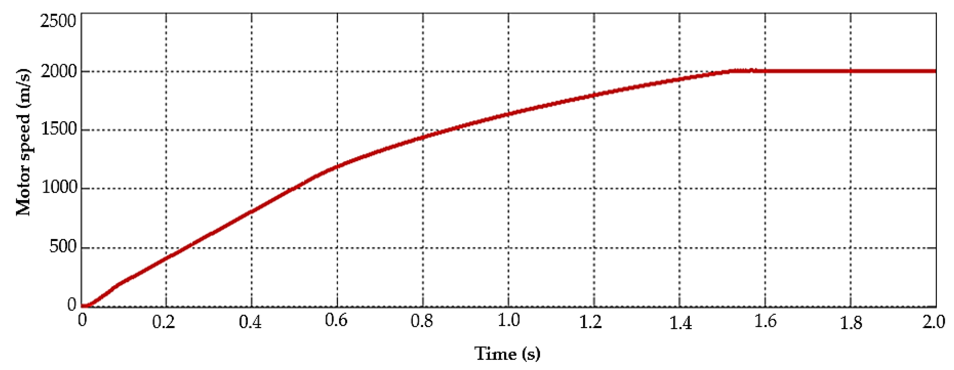
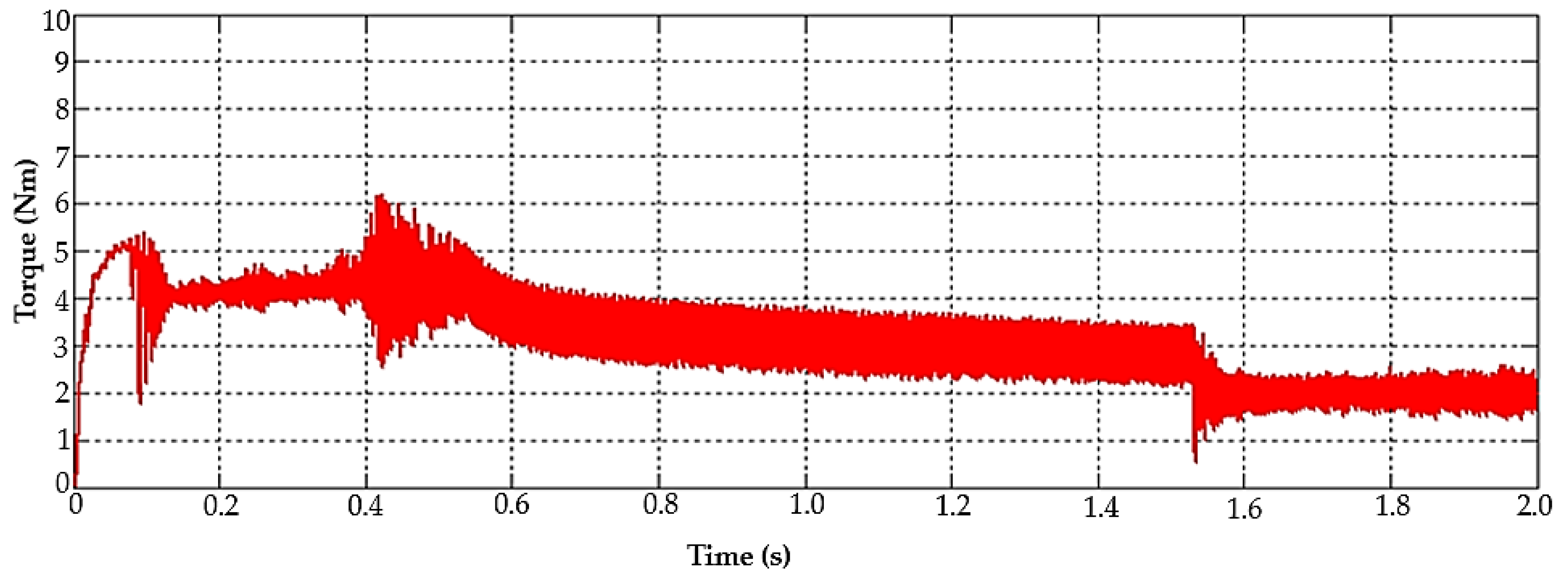
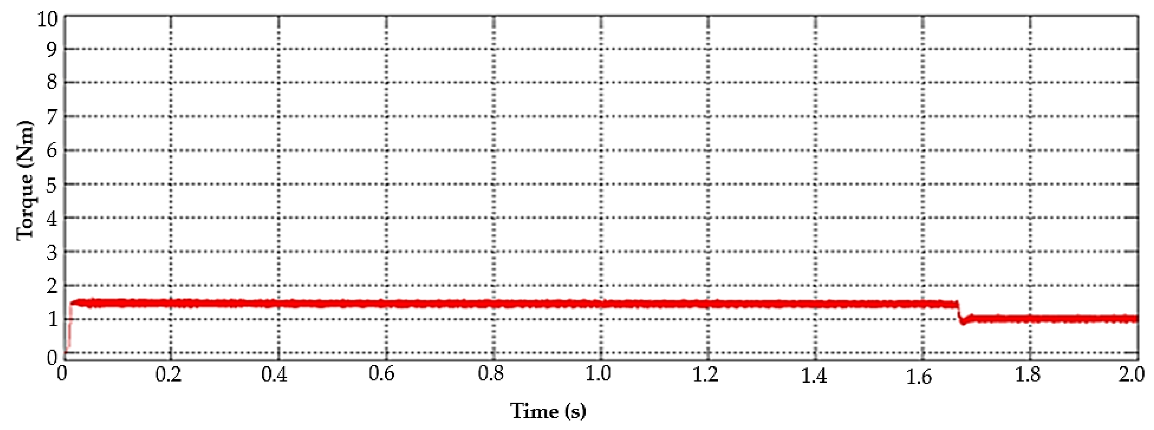
5.1.2. BLDC Motor Pump Performance
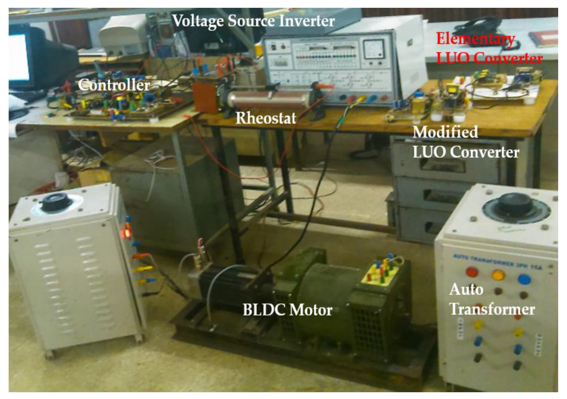
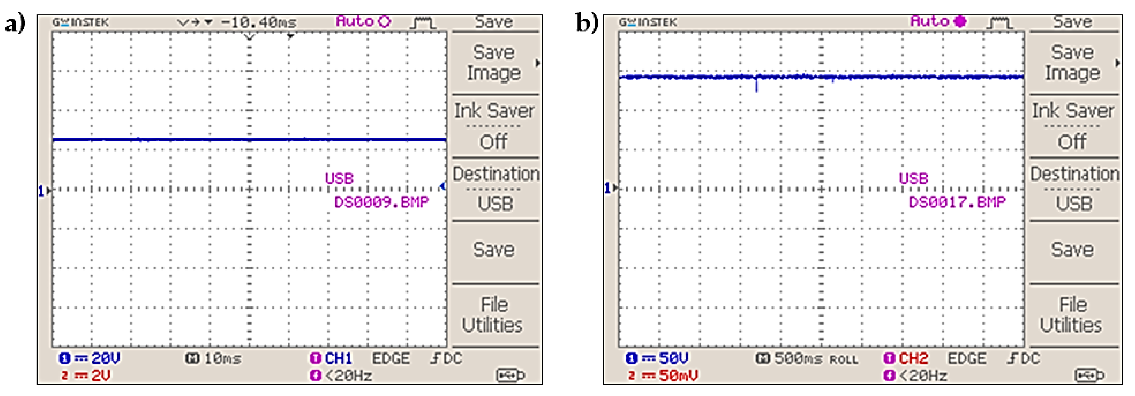
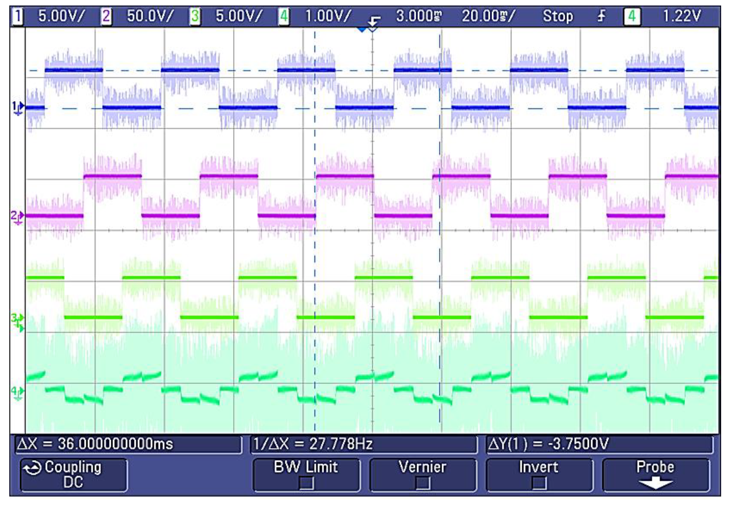
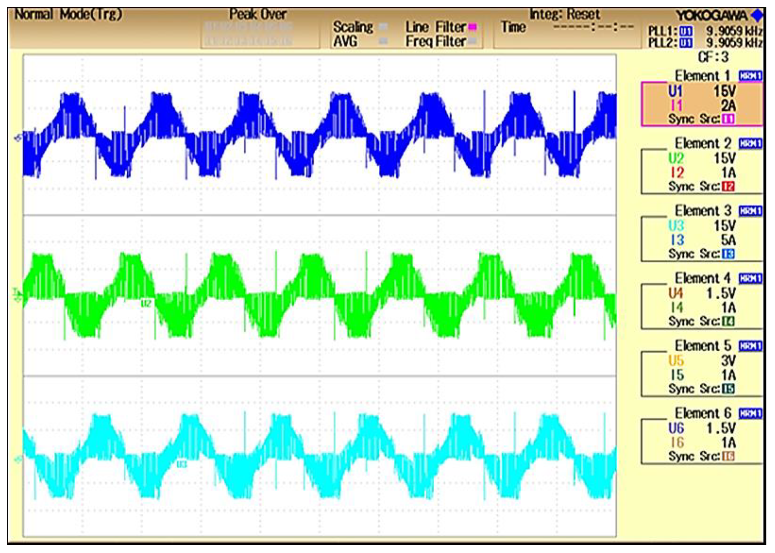
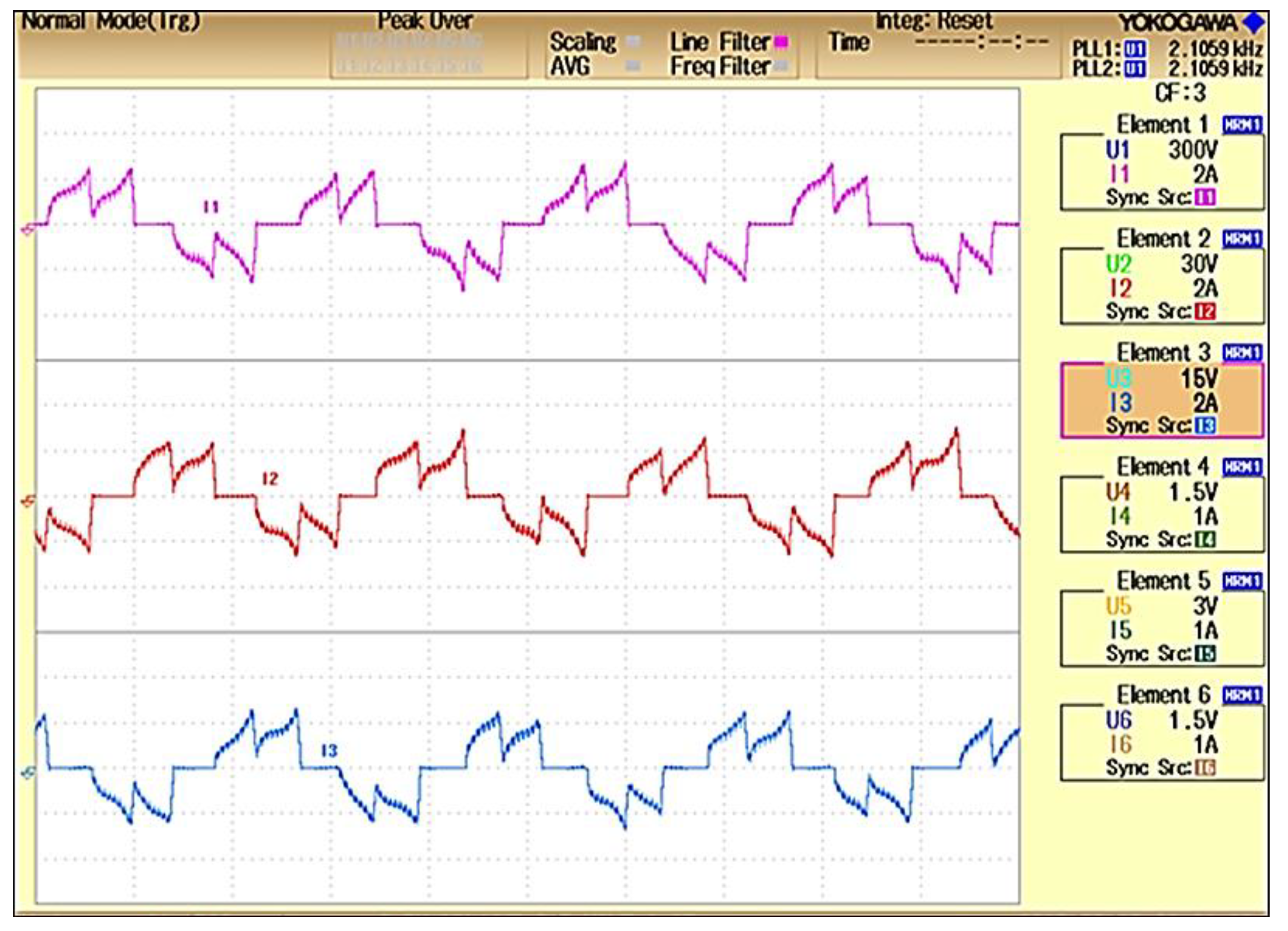
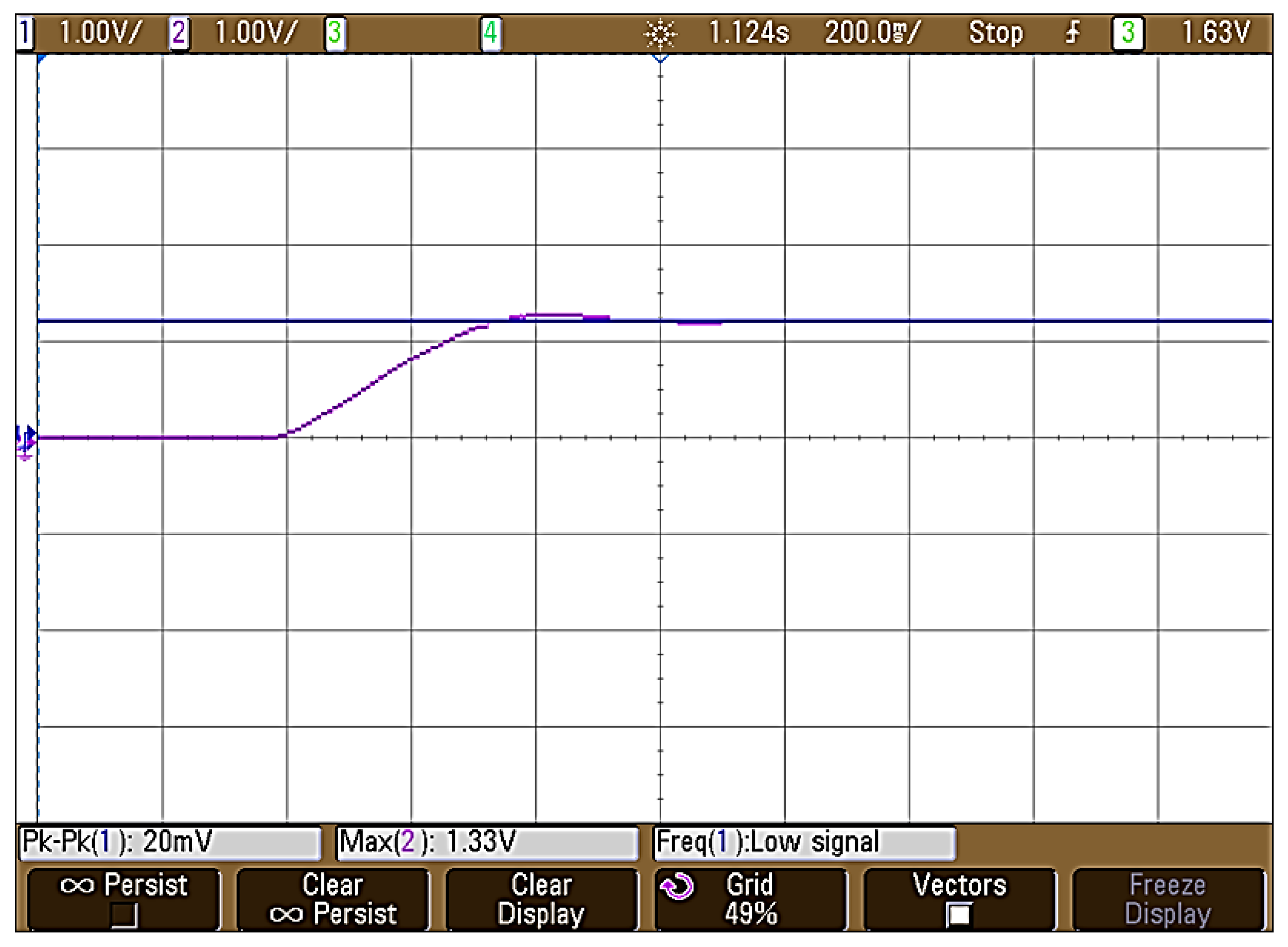
5.2. Experimental Results
6. Conclusions
Author Contributions
Funding
Acknowledgments
Conflicts of Interest
References
- Bist, V. An Adjustable Speed PFC Bridgeless-SEPIC. In Proceedings of the 2015 IEEE Energy Conversion Congress and Exposition (ECCE), Montreal, QC, Canada, 20–24 September 2015; pp. 4886–4893. [Google Scholar]
- Hong, D.K.; Woo, B.C.; Koo, D.H.; Seo, U.J. A single-phase brushless DC motor with improved high efficiency for water cooling pump systems. IEEE Trans. Magn. 2011, 47, 4250–4253. [Google Scholar] [CrossRef]
- Chand, V.; Kalamkar, V.R. Solar photovoltaic water pumping system—A comprehensive review. Renew. Sustain. Energy Rev. 2016, 59, 1038–1067. [Google Scholar]
- Singh, S.; Singh, B. Power factor correction in permanent magnet brushless DC motor drive using single-phase Cuk converter. J. Eng. Sci. Technol. 2010, 5, 412–425. [Google Scholar]
- Shi, T.; Guo, Y.; Song, P.; Xia, C. A New Approach of Minimizing Commutation Torque Ripple for Brushless DC Motor Based on DC–DC Converter. IEEE Trans. Ind. Electron. 2010, 57, 3483–3490. [Google Scholar] [CrossRef]
- Hendershot, J.R.; Miller, T.J.E. Design of Brushless PM Motors; Magna Publishing: Hillsborough, OH, USA, 1994. [Google Scholar]
- Mandel, Y.; Weiss, G. Reduction of torque ripple in brushless DC motor drives. IFAC Proc. Vol. 2009, 42, 84–89. [Google Scholar] [CrossRef]
- Bahari, N.B.; Jidin, A.B.; Abdullah, A.R.B.; Othman, M.N.B.; Manap, M.B. Modeling and simulation of torque hysteresis controller for brushless DC motor drives. In Proceedings of the 2012 IEEE Symposium on Industrial Electronics and Applications, Bandung, Indonesia, 23–26 September 2012; pp. 152–155. [Google Scholar]
- Mohanty, S.; Subudhi, B.; Member, S.; Ray, P.K. A New MPPT Design Using Grey Wolf Optimization Technique for Photovoltaic System Under Partial Shading Conditions. IEEE Trans. Sustain. Energy 2015, 7, 1–8. [Google Scholar] [CrossRef]
- G, D.; Singh, S.N. Selection of non-isolated DC–DC converters for solar photovoltaic system. Renew. Sustain. Energy Rev. 2017, 76, 1230–1247. [Google Scholar] [CrossRef]
- Singh, B.; Singh, S.; Chandra, A.; Al-Haddad, K. Comprehensive study of single-phase AC-DC power factor corrected converters with high-frequency isolation. IEEE Trans. Ind. Inform. 2011, 7, 540–556. [Google Scholar] [CrossRef]
- Zhang, X.; Lu, Z. A new BLDC motor drives method based on BUCK converter for torque ripple reduction. In Proceedings of the 2006 CES/IEEE 5th International Power Electronics and Motion Control Conference, Shanghai, China, 14–16 August 2006; Volume 3, pp. 1631–1635. [Google Scholar]
- Richter, M. Zeitverschwendung. Dtsch. Arztebl. Int. 2017, 114, A2358. [Google Scholar]
- Singh, B.; Bist, V. A BL-CSC converter-fed BLDC motor drive with power factor correction. IEEE Trans. Ind. Electron. 2015, 62, 172–183. [Google Scholar] [CrossRef]
- Singh, P.K.; Singh, B.; Bist, V. PFC converter based power quality improvement and ripple current minimization in BLDC motor drive. In Proceedings of the 2016 IEEE 6th International Conference on Power Systems (ICPS), New Delhi, India, 4–6 March 2016; pp. 1–6. [Google Scholar]
- Bist, V.; Singh, B. PFC Cuk converter-fed BLDC motor drive. IEEE Trans. Power Electron. 2015, 30, 871–887. [Google Scholar] [CrossRef]
- Kumar, R.; Singh, B. Buck-Boost Converter Fed BLDC Motor Drive for Solar PV Array Based Water Pumping. In Proceedings of the 2014 IEEE International Conference on Power Electronics, Drives and Energy Systems (PEDES), Mumbai, India, 16–19 December 2014; p. 4. [Google Scholar]
- Kumar, R.; Singh, B. BLDC Motor-Driven Solar PV Array-Fed Water Pumping System Employing Zeta Converter. IEEE Trans. Ind. Appl. 2016, 52, 2315–2322. [Google Scholar] [CrossRef]
- Berkovich, Y.; Madar, R.; Axelrod, B.; Twina, A. Improved Luo converter modifications with increasing voltage ratio. IET Power Electron. 2015, 8, 202–212. [Google Scholar] [CrossRef]
- Kumar, R.; Singh, B. Solar PV array fed cuk converter-VSI controlled BLDC motor drive for water pumping. In Proceedings of the 2014 6th IEEE Power India International Conference (PIICON), Delhi, India, 5–7 December 2014; pp. 1–31. [Google Scholar]
- Sivakumar, S.; Sathik, M.J.; Manoj, P.S.; Sundararajan, G. An assessment on performance of DC-DC converters for renewable energy applications. Renew. Sustain. Energy Rev. 2016, 58, 1475–1485. [Google Scholar] [CrossRef]
- Oshaba, A.S.; Ali, E.S.; Elazim, S.M.A. MPPT Control Design of PV Generator Powered DC Motor-Pump System based on Artificial Bee Colony Algorithm. WSEAS Trans. POWER Syst. 2016, 11, 190–198. [Google Scholar]
- El-samahy, A.A.; Shamseldin, M.A. Brushless DC motor tracking control using self-tuning fuzzy PID control and model reference adaptive control. Ain Shams Eng. J. 2018, 9, 341–352. [Google Scholar] [CrossRef]
- Premkumar, K.; Manikandan, B.V. Engineering Science and Technology, an International Journal Bat algorithm optimized fuzzy PD based speed controller for brushless direct current motor. Eng. Sci. Technol. Int. J. 2016, 19, 818–840. [Google Scholar]
- Depuru, S.R.; Mahankali, M. Boost converter Fed High Performance BLDC Drive for Solar PV array Powered Air Cooling System. Power Eng. Electr. Eng. 2017, 15, 154–168. [Google Scholar] [CrossRef]
- Akkaya, R.; Kulaksiz, A.A.; Aydoǧdu, Ö. DSP implementation of a PV system with GA-MLP-NN based MPPT controller supplying BLDC motor drive. Energy Convers. Manag. 2007, 48, 210–218. [Google Scholar] [CrossRef]
- Femia, N.; Petrone, G.; Spagnuolo, G.; Vitelli, M. Optimization of perturb and observe maximum power point tracking method. IEEE Trans. Power Electron. 2005, 20, 963–973. [Google Scholar] [CrossRef]
- Killi, M.; Samanta, S. Modified perturb and observe MPPT algorithm for drift avoidance in photovoltaic systems. IEEE Trans. Ind. Electron. 2015, 62, 5549–5559. [Google Scholar] [CrossRef]
- Hohm, D.P.; Ropp, M.E. Comparative study of maximum power point tracking algorithms using an experimental, programmable, maximum power point tracking test bed. In Proceedings of the Conference Record of the Twenty-Eighth IEEE Photovoltaic Specialists Conference—2000, Anchorage, AK, USA, 15–22 September 2000; pp. 1699–1702. [Google Scholar]
- Terki, A.; Moussi, A.; Betka, A.; Terki, N. An improved efficiency of fuzzy logic control of PMBLDC for PV pumping system. Appl. Math. Model. 2012, 36, 934–944. [Google Scholar] [CrossRef]


| Parameter | Value with Units |
|---|---|
| Peak power (Pmp) | 100 W |
| Open Circuit Voltage (Voc) | 22.68 V |
| Short circuit current (Isc) | 5.86 A |
| Peak power voltage (Vmp) | 18.75 V |
| Peak power current (Imp) | 5.42 A |
| Number of series-connected cells (Ns) | 36 |
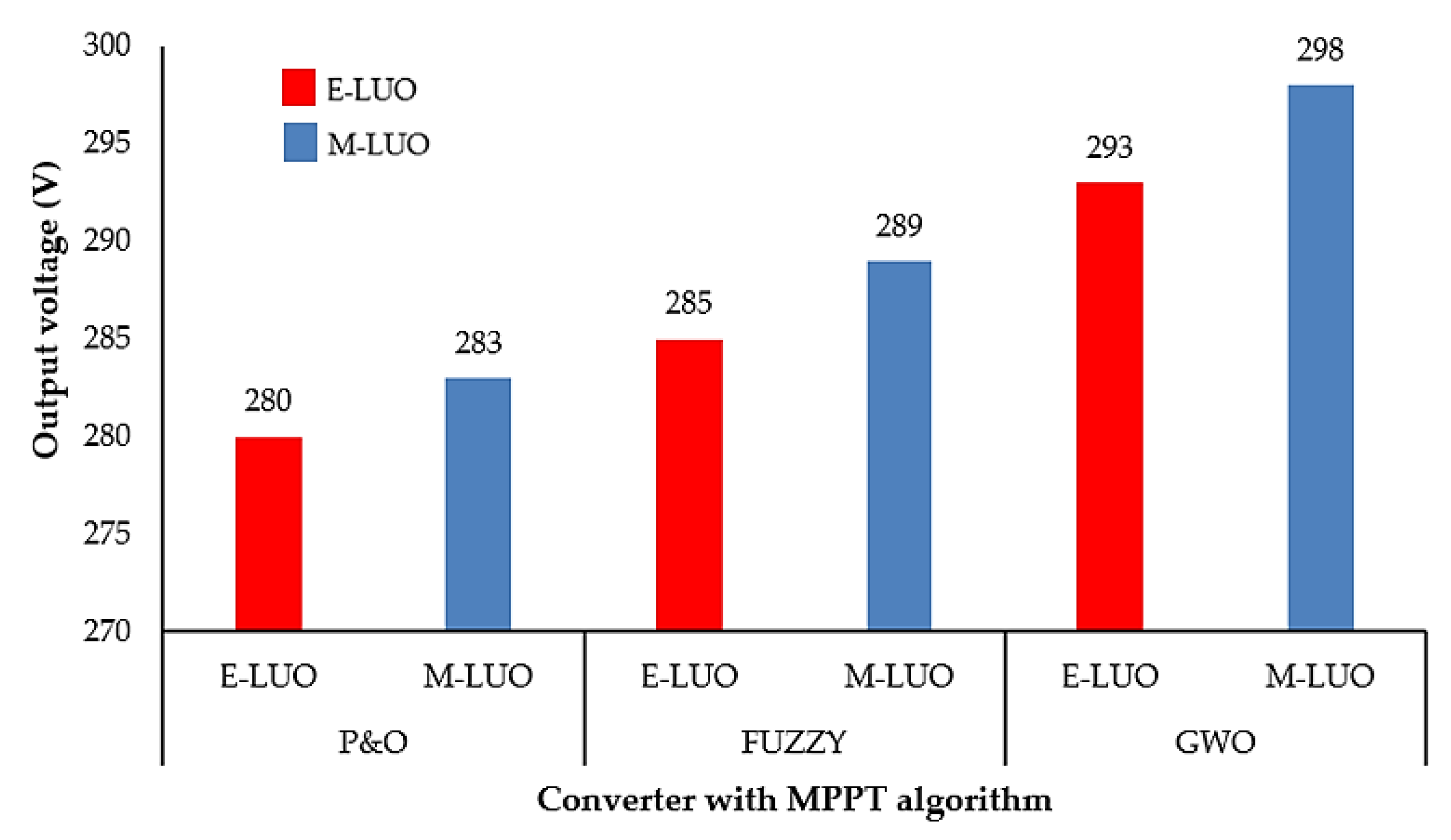
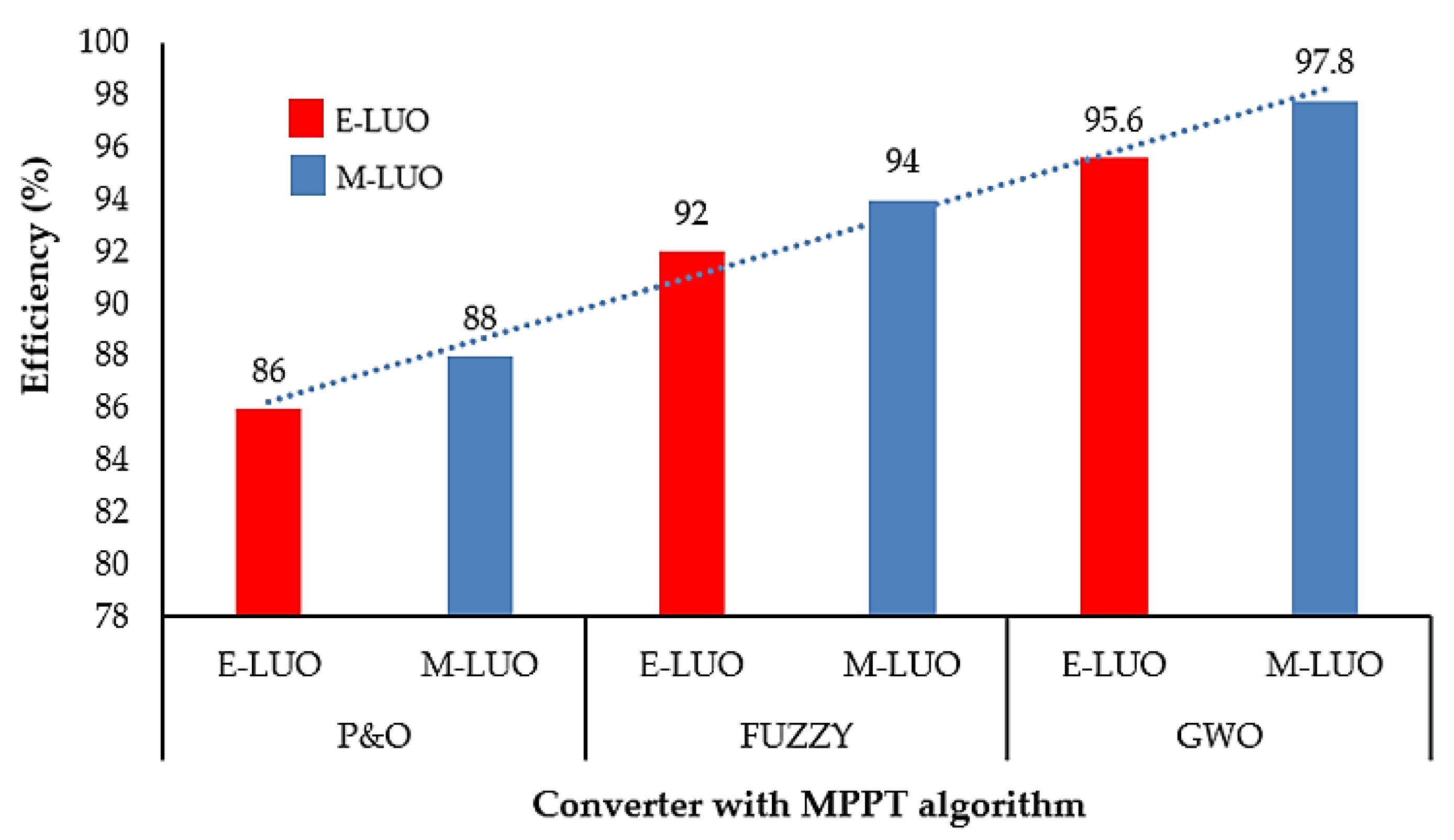
| MPPT Methods /Converter. | Steady-State Settling Time (s) | Output Voltage (V) | Efficiency (%) | |
|---|---|---|---|---|
| P&O | Elementary LUO Converter | 0.02 | 280 | 86 |
| Modified LUO Converter | 0.019 | 283 | 88 | |
| Fuzzy | Elementary LUO Converter | 0.018 | 285 | 92 |
| Modified LUO Converter | 0.016 | 289 | 94 | |
| GWO | Elementary LUO Converter | 0.01 | 293 | 95.6 |
| Modified LUO Converter | 0.009 | 298 | 97.8 | |
© 2020 by the authors. Licensee MDPI, Basel, Switzerland. This article is an open access article distributed under the terms and conditions of the Creative Commons Attribution (CC BY) license (http://creativecommons.org/licenses/by/4.0/).
Share and Cite
Darcy Gnana Jegha, A.; Subathra, M.S.P.; Manoj Kumar, N.; Subramaniam, U.; Padmanaban, S. A High Gain DC-DC Converter with Grey Wolf Optimizer Based MPPT Algorithm for PV Fed BLDC Motor Drive. Appl. Sci. 2020, 10, 2797. https://doi.org/10.3390/app10082797
Darcy Gnana Jegha A, Subathra MSP, Manoj Kumar N, Subramaniam U, Padmanaban S. A High Gain DC-DC Converter with Grey Wolf Optimizer Based MPPT Algorithm for PV Fed BLDC Motor Drive. Applied Sciences. 2020; 10(8):2797. https://doi.org/10.3390/app10082797
Chicago/Turabian StyleDarcy Gnana Jegha, A., M. S. P. Subathra, Nallapaneni Manoj Kumar, Umashankar Subramaniam, and Sanjeevikumar Padmanaban. 2020. "A High Gain DC-DC Converter with Grey Wolf Optimizer Based MPPT Algorithm for PV Fed BLDC Motor Drive" Applied Sciences 10, no. 8: 2797. https://doi.org/10.3390/app10082797
APA StyleDarcy Gnana Jegha, A., Subathra, M. S. P., Manoj Kumar, N., Subramaniam, U., & Padmanaban, S. (2020). A High Gain DC-DC Converter with Grey Wolf Optimizer Based MPPT Algorithm for PV Fed BLDC Motor Drive. Applied Sciences, 10(8), 2797. https://doi.org/10.3390/app10082797