Article

Positioning Accuracy of the Shearer Based on a Strapdown Inertial Navigation System in Underground Coal Mining

1
Key Laboratory of Deep Coal Resource Mining, Ministry of Education of China, Xuzhou 221116, China
2
School of Mines, University of Mining and Technology, Xuzhou 221116, China
*
Author to whom correspondence should be addressed.
Appl. Sci. 2020, 10(6), 2176; https://doi.org/10.3390/app10062176
Submission received: 2 January 2020 / Revised: 18 March 2020 / Accepted: 20 March 2020 / Published: 23 March 2020
(This article belongs to the Section Mechanical Engineering)

Abstract

:
Automation and intelligent coal mining comprise the most important fields in coal mining technology research. The key to automation and intelligent coal mining is the automated mining of the working face, and accurate positioning of the shearer is one of the most important technologies in the automated mining process. However, significant defects in non-inertial navigation system (INS)-based methods have led to low positioning accuracy. In this paper, we propose a new shearer positioning technology to further improve the positioning accuracy of the shearer and monitor the shearer position in real time. The shearer positioning system proposed is based on the strapdown inertial navigation system (SINS). We conducted shearer positioning experiments with gyroscopes, accelerometers, and other inertial navigation instruments. The experimental results are thoroughly studied on the basis of error compensation techniques such as inertial instrument zero bias compensation and Kalman filter compensation. Compared with traditional shearer positioning technology, the experimental results show that the shearer positioning system based on SINS can achieve more accurate positioning of the shearer and can accurately reflect the running characteristics of the shearer working the mining face.

1. Introduction

China is the largest coal producer and consumer in the world according to the World Energy Annual Report in 2018. In 2017, China produced 3523 million metric tons of coal, accounting for 46% of the world’s coal production, and China’s coal consumption accounts for 51% of the world’s coal consumption. This also led to China becoming the country with the most coal mine accidents and highest number of mining injuries and deaths, especially because >90% of China’s coal is produced in underground coal mines [1]. In view of the above problems, China is implementing intelligent mining technology in coal mines nationwide [2,3]. The goal of intelligent mining technology is to realize highly automated and efficient mining through intelligent sensing of the mining environment, intelligent decision-making, and automatic control of mining equipment [4,5]. Through automated and intelligent technology, miners can be transferred from the dangerous working face to the roadway or to the ground to work during the mining process, thereby greatly reducing casualties [6].
Currently, mechanization of coal mining equipment has been realized in most coal mines in China, but the automation and intelligence level of coal mining needs to be improved [7,8]. To achieve intelligent mining, it is necessary to deploy highly automated mining equipment at the working face [9]. The main equipment at the working face includes the shearer, hydraulic supports, and a scraper conveyor, with the shearer being the most important component. The shearer is the piece of equipment used for coal cutting and loading at the working face. During the mining process, the shearer runs on the track of the scraper conveyor, and the coal is transported to the roadway on the scraper conveyor. The hydraulic supports support the roof and isolate the goaf to provide working space for the shearer and scraper conveyor. The equipment layout of a typical fully mechanized mining face is shown in Figure 1.
Accurate position information of the shearer is the key to realizing automatic coal cutting and hydraulic support automatic shifting, and it is also the key to realizing shear memory cutting and adaptive cutting [10]. Therefore, precise positioning of the shearer is one of the most important technologies in intelligent mining. However, because most coal mines are underground in China, conventional ground positioning methods, such as radio navigation, satellite positioning, and astronomical navigation, cannot function [11,12]. Conventional shearer positioning methods, such as infrared radiation, ultrasonic reflection, gear counting, and wireless sensor network methods, do not meet the accuracy requirements for automated mining [13,14]. To achieve precise positioning of the shearer, a strapdown inertial navigation positioning method is proposed in this article.
Strapdown inertial navigation system (SINS) is a navigation system in which inertial devices are directly fixed onto the running carrier. The angular velocity and acceleration of the running carrier are measured by a gyroscope and an accelerometer, respectively, and, when these are combined with the initial inertia information of the running carrier, navigation information such as the speed, position, course, and attitude can be obtained by calculation [15,16]. SINS was developed on the basis of the platform inertial navigation system (PINS), which uses a mathematical platform instead of a physical platform, and has no complicated frame structure nor servo system. Compared with the traditional navigation system, SINS has the advantages of its light weight, small size, low cost, and high reliability [17]. Moreover, owing to the emergence of inertial devices such as laser gyros and fiber optic gyros, the rapid development of computer technology, and improvements in computational theory, the advantages of strapdown inertial navigation systems are more prominent. SINS can then be applied to the localization of the shearer in the coal mine environment [18].
Fan et al. [19] proposed a shearer positioning error analysis model of a SINS using the extended Kalman filter. However, in a coal mine environment filled with dust, noise and humidity, the SINS will suffer from the mechanical vibration of the shearer and lead to large measuring errors. There are many factors that can cause the mechanical vibration of a shearer, such as the cutting of discontinuous coal, inaccurate installation of the shearer drums and distributing the picks non-uniformly around the drum [20]. Moreover, the shearer breaks the coal with a rotary impact motion, which can produce vibration of the shearer fuselage and drums. Scholars have researched the dynamic model of shearers and analyzed their mechanical vibration. Dolipski et al. [21] described the dynamic model of a shearer cutting system and calculated the differential equations of the dynamic model using the Runge-Kutta iterative method.
Currently, the widely used SINS utilizes low-cost micro electro mechanical systems (MEMS) inertial sensors, which directly measure acceleration and angular rate [22]. Unfortunately, the gear eccentricity and manufacturing error and clearances at joints can cause angular vibration and linear vibration of the shearer [23]. The mechanical vibration of the shearer fuselage, including angular vibration and linear vibration, can reduce the accuracy of the measured acceleration and angular velocity, resulting in the positioning error of the SINS [24]. The angular vibration can lead to a coning error, which can affect the calculation of the attitude update [25]. Meanwhile, the angular vibration and linear vibration can lead to a sculling error, which will affect the calculation of velocity update and position update [26]. The study of these two errors is common. Since Bortz [27] proposed the theory of the rotation vector in 1971, the noncommutativity error of SINS has been effectively solved [28]. Kang et al. [29] proposed a direct coning mitigation algorithm based on the sinusoidal component of gyro measurements. This algorithm can be applied to the mitigation of sculling errors. Lai et al. [30] analyzed the SINS coning error for the vibration of unmanned aerial vehicles and proposed an integrated vibration model between sinusoidal angular vibration and random angular vibration. Meanwhile, the coning error is compensated by the multi-sample algorithm.
In this paper, we established a shearer positioning system for a fully mechanized working face based on the SINS [31], and we conducted an independent positioning experiment on the shearer. The experimental results show that the shearer positioning system based on SINS can accurately reflect the position information of the shearer.

2. Shearer Positioning System Based on SINS

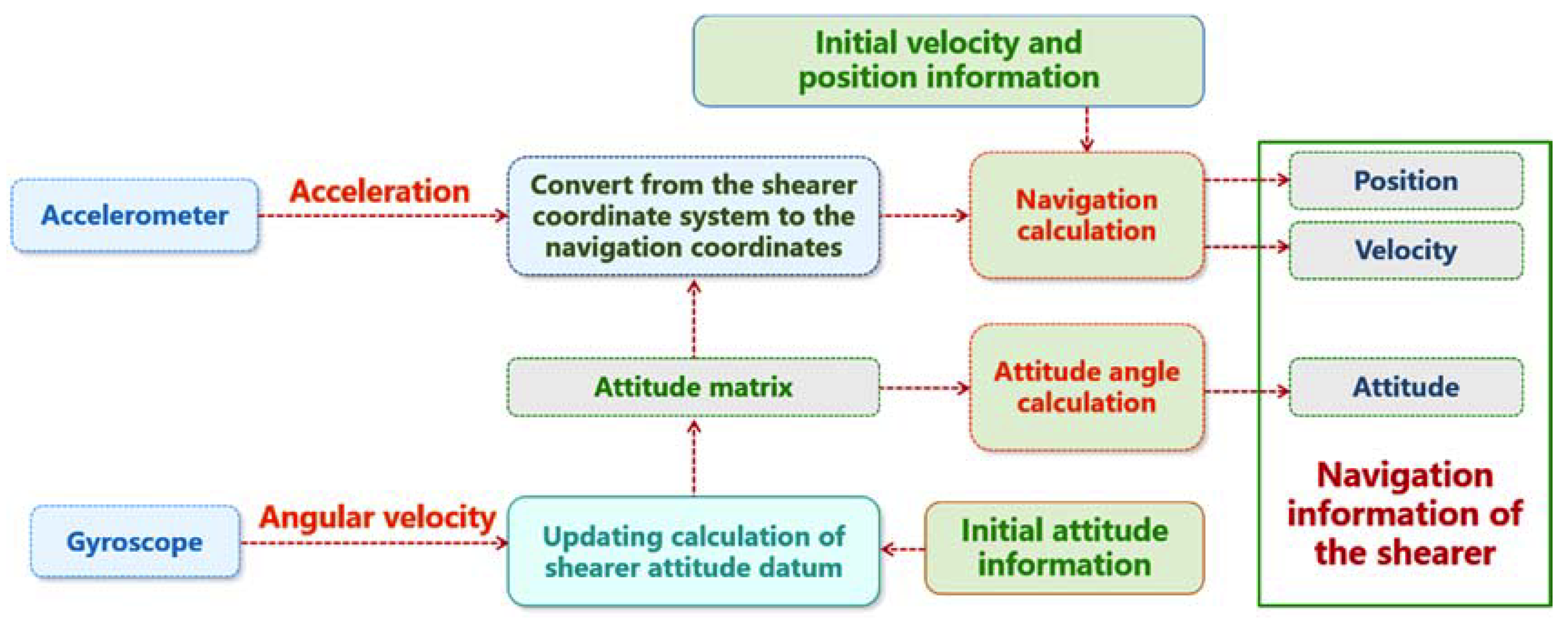
2.1. Principle of the Shearer Positioning System Based on SINS

SINS is applied to the shearer to detect the position and attitude of the shearer. The angular velocity and acceleration of the shearer are also detected by using an inertial measurement unit (IMU). Then, the position and attitude information of the shearer can be obtained by calculations [32]. As shown in Figure 2, because the position and attitude of the shearer are three-dimensional, the IMU of the shearer positioning system is not a single-axis gyroscope and an accelerometer, but a three-axis gyroscope and a three-axis accelerometer, whose axes are orthogonal.
Shearer positioning entails actually determining the coordinates of the shearer relative to a certain reference coordinate system at a certain time [33]. However, the angular velocity and acceleration measured by the shearer positioning system are in the carrier coordinate system and cannot be directly used for the calculation of the position and attitude of the shearer. To solve the position and attitude of the shearer, it is necessary to convert the carrier coordinate system to the navigation coordinate system. Most mine maps are based on the geographic coordinate system. The geographic coordinate system is used as the navigation coordinate system; this will alleviate the need to convert the mine map coordinate information in the navigation coordinate system, reducing the calculation burden of the positioning system [34,35,36,37,38].
The attitude of the shearer is the orientation relationship between the carrier coordinate system and the geographic coordinate system. If we let the heading angle be φ, the pitch angle be θ, and the roll angle be γ, then the orientation relationship between the carrier coordinate system and the geographic coordinate system is as shown in Figure 3.
The following is the transformation matrix from the carrier coordinate system to the geographic coordinate system [39]:
C t b = C γ C θ C φ = ( cos γ 0 sin γ 0 1 0 sin γ 0 cos γ ) ( 1 0 0 0 cos θ sin θ 0 sin θ cos θ ) ( cos φ sin φ 0 sin φ cos φ 0 0 0 1 ) =
( cos γ cos φ sin γ sin θ sin φ cos γ sin φ + sin γ sin θ cos φ sin γ cos θ sin φ cos θ cos φ cos θ sin θ sin γ cos φ cos γ sin φ sin θ sin γ sin φ cos γ sin φ cos θ cos γ cos θ )
Obviously, matrix C t b is an orthogonal matrix, then,
C b n = C b t = ( C t b ) T = ( cos γ cos φ sin γ sin θ sin φ sin φ cos θ sin γ cos φ cos γ sin φ sin θ cos γ sin φ + sin γ sin θ cos φ cos φ cos θ sin γ sin φ cos γ sin φ cos θ sin γ cos θ sin θ cos γ cos θ )
Matrix C b n is called an attitude matrix or a strapdown matrix. The angular velocity measured by the gyroscope can update the attitude matrix in real time, and the attitude matrix can be solved to obtain the information of the shearer attitude angle. The acceleration measured by the accelerometer also uses the attitude matrix to convert the system from a shearer coordinate system to a navigation coordinate system and calculate the velocity and position of the shearer. In brief, the shearer positioning system based on SINS is shown in Figure 4.
To further improve the accuracy of the positioning system, orbital odometer positioning technology is introduced to correct the SINS displacement signal [40,41]. The running distance of the shearer on the scraper conveyor is monitored by the travel gear sensor, and the running distance is calculated according to the circumference of the gear travel. The running distance obtained by the odometer is accurate, and the orbital odometer positioning technology is simple, reliable, and easy to implement.

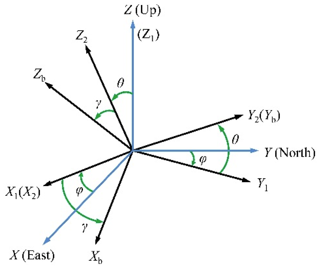
2.2. Calculation of the Shearer Positioning System Based on SINS

After the attitude matrix is solved, the following formula can be used to determine the three-dimensional acceleration of the shearer in the geographic coordinate system [42]:
a = C a b
where a is the three-dimensional acceleration of the shearer in the geographic coordinate system and a b is the three-dimensional acceleration of the shearer in the carrier coordinate system. The shearer positioning result is obtained from the following formula:
S k + 1 = S k + V k t + 1 2 a k + 1 t 2
where Sk+1 and Sk are the three-dimensional positions of the shearer in the geographic coordinate system at the kth and (k+1)th data sampling moments, respectively, Vk is the three-dimensional velocity of the shearer in the geographic coordinate system at the kth data sampling moment, t is the data sampling duration, and a k + 1 is the three-dimensional acceleration of the shearer in the geographic coordinate system at the (k+1)th data sampling moment.

3. Shearer Positioning System Based on SINS

Because the environment in which the shearer works underground is very complicated, high precision is required to meet shearer positioning needs. Before field application, it must undergo rigorous testing and experiments to determine whether it can meet the real-time, accuracy, and reliability requirements of underground positioning.

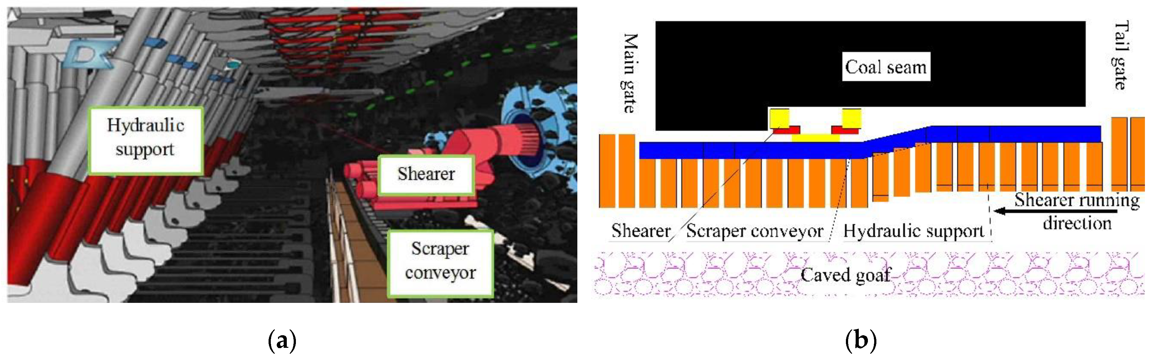
3.1. Motion Characteristics of the Shearer

Due to the limitation of the underground operating environment, the shearer can only operate in narrow space. At the same time, the working characteristics of the shearer also lead to the simple motion process. During the mining process, the shearer runs on the track of the scraper conveyor along the working face, and, vertically to the working face, the shearer is moved by the push of the scraper conveyor.
The starting position of the shearer is on the roadway, and then the shearer cuts the coal along the working face. The common sumping modes of the shearer are inclined sumping at the end or in the middle of the working face. If we take the inclined sumping at the end of the working face as an example, the motion process is shown in Figure 5. It can be seen from the figure that the movement of the shearer mainly has two states: coal cutting along the working face and inclined-sumping coal cutting. This allows us to simplify the shearer movement into two states: linear motion and bending motion.

3.2. Experimental Design

To demonstrate the applicability of the shearer positioning system and the effectiveness of the data processing method, the actual movement of the shearer was simplified and the movement route of the experimental device was planned. The movement process of the shearer on the working face is simulated, the data output from the gyroscope and accelerometer is collected for data processing, and the characteristics of the motion path are recorded. Combined with the data output from the odometer, the positioning accuracy of the shearer positioning system was studied experimentally.
Under THE current conditions of mining technology, the length of a fully mechanized mining face is usually 200 m. The designed experimental route length is 2 m, and the length of the curved section of the scraper conveyor is 0.2 m. Because of different coal mining processes, the inclined sumping can be located in the middle or at both ends of the working face. Therefore, four routes were designed for testing, as shown in Figure 6.
When the shearer does not cut coal, the scraper conveyor is usually in a straight line shape. For this reason, a straight line running experiment is designed, as shown in Figure 6a, where the positioning device runs from A to B over a running distance of 2 m. In the experiment, four sets of experiments were performed using different motion velocities to test the time effect of the positioning effect. According to the different sumping positions on the working face, three experimental paths are designed, as shown in Figure 6b–d. Each moving path tests two sets of data at motion speeds to compare and analyze the positioning accuracy of different data processing methods.

3.3. Experimental Data Processing Methods

As can be seen from Equation (4), the shearer speed and position at each sampling time are derived from the speed and position at the last sampling time. If there is an error in the acceleration data measured at a certain time, the error will always exist in the later calculation, so the error of SINS positioning will gradually accumulate. Consequently, the positioning accuracy of SINS will decrease with time. To solve the problem of error accumulation over time, a Kalman filter algorithm is introduced to eliminate part of the positioning error [43,44].
The Kalman filter equations for shearer positioning are as follows. State transition equation:
X k + 1 = Φ k + 1 | k X k + ω k .
Observation equation:
Z k + 1 = H k + 1 X k + 1 + ν k + 1 .
In Equation (5), X k + 1 is a state vector, given by
X k + 1 = [ x k + 1 v x | k + 1 a x | k + 1 y k + 1 v y | k + 1 a y | k + 1 z k + 1 v z | k + 1 a z | k + 1 ] T
where [ x k + 1 y k + 1 z k + 1 ] , [ v x | k + 1 v y | k + 1 v z | k + 1 ] , and [ a x | k + 1 a y | k + 1 a z | k + 1 ] are the actual shearer positioning, velocity, and acceleration, respectively, Φ k + 1 | k is a state transition matrix, and ω k is a process noise vector.
In Equation (6), Zk+1 is an observation vector, given by
Z k + 1 = [ x k + 1 v x | k + 1 a x | k + 1 y k + 1 v y | k + 1 a y | k + 1 z k + 1 v z | k + 1 a z | k + 1 ] T
where [ x k + 1 y k + 1 z k + 1 ] , [ v x | k + 1 v y | k + 1 v z | k + 1 ] , and [ a x | k + 1 a y | k + 1 a z | k + 1 ] are the observation shearer positioning, velocity, and acceleration, respectively, where H k + 1 is an observation vector and ν k + 1 is an observation noise vector.
The Kalman filtering process of shearer positioning is as follows:
X ^ k + 1 | k = Φ k + 1 | k X ^ k
where X ^ k + 1 | k is the predicted value of X ^ k and X ^ k is the optimal estimated state vector of X k . Also, the predicted value of P k is
P k + 1 | k = Φ k + 1 | k P k Φ k + 1 | k T + Q k
where P k , P k + 1 | k , Q k , and O k + 1 are the covariance matrices of X k , X k + 1 , ω k and ν k , respectively, and P k is the covariance matrix of the state vector.
The filter gain matrix is
K k + 1 = P k + 1 | k H k + 1 T [ H k + 1 P k + 1 | k H k + 1 | k T + O k + 1 ] 1
The optimal estimated state vector of X k + 1 is
X ^ k + 1 = X ^ k + 1 | k + K k + 1 ( Z k + 1 H k + 1 X ^ k + 1 | k )
and
P k + 1 = P k + 1 | k ( I K k + 1 H k + 1 )
where I is the identity matrix.
In this experiment, the data obtained after compensation are decomposed along the X- and Y-axis directions, and the distribution of the estimated points is determined according to the dead reckoning principle and formula fitting.

4. Analysis of the Experimental Results

4.1. Straight-Line Running Positioning Experiments

In the straight line running positioning experiment, we deployed four schemes according to different running times (37, 28, 22, and 12 s, respectively). According to Formula 4, we can get the positioning results of the shearer, but we need to process the experimental data through the Kalman filter in 3.3 firstly, and zero bias compensation and 10-point smoothing preprocessing are also used to process the experimental data. Figure 7 shows a comparison of the shearer coordinate distribution obtained by using the original data and after error compensation.
During the experiment, the odometer received a pulse signal output from the Hall sensor, and each pulse represented a distance of 0.3297 cm. The pulse data output from the odometer for the above four experimental schemes is given in Table 1. Because the shearer undergoes linear motion during the experiment, the trajectory equation of the shearer is Y = 0 (0 ≤ X ≤ 2). The positioning errors of the final point under different motion times are listed in Table 2.
Through the straight line running positioning experiment, the following can be concluded:
  • The estimated points of the integral calculation after error compensation accurately reflect the linear operation characteristics of the shearer. By comparing the positioning results obtained before and after compensation, it can be seen that, after 10-point smoothing preprocessing, zero bias compensation, and Kalman filter compensation of the output gyroscope and accelerometer data, the validity of the data increases greatly, and the error is significantly reduced. The position of the shearer estimated by the positioning system surrounds the actual trajectory;
  • The error of the position point on the X axis is greater than that on the Y axis. The maximum error measured along the direction of the shearer movement is 0.11 m. Therefore, there is an error in measuring the displacement of the shearer by relying solely on the accelerometer. The error is mainly related to the working principle of the instrument. The data measured by the accelerometer needs to be integrated twice to obtain the distance information. In practice, the map-matching technique can be used for correction;
  • The displacement accuracy measured by the odometer is higher than that of the accelerometer. The displacement measured by the odometer is less than the actual displacement. The main reason for this error is the slip between the walking wheel and the track. Moreover, slip is less likely to occur on the chainless shearer, so the odometer has higher reliability and can correct the acceleration integral result;
  • The number of isolated points is proportional to the running time. By comparing the four experimental schemes, it can be found that the longer the running time, the greater the number of isolated points and the greater the absolute value of the discrete quantities. This is related to the drift characteristics of the inertial meter over time. To meet the long-term positioning requirements, a more accurate instrument can be used. In the case of straight line running, the discrete amount of the isolated points in the Y direction can be corrected by map matching. By projecting the isolated points on a straight line map, it can be ensured that the shearer is positioned on the scraper conveyor and reducing positioning errors. The positioning results after the map matching is shown in Figure 8;
  • The density of the coordinate points reflects the operating speed of the shearer. In the experiment, the cycle of positioning calculation is controlled by the system time. At the same sampling frequency, the slower the running speed, the more detailed the sampling data is. Therefore, the running speed of the coal shearer is related to the density of the coordinate points. The slower the shearer runs, the denser the coordinate points. Therefore, the positioning system can not only reflect the position information of the shearer in real time, but also display the speed in each operating section.

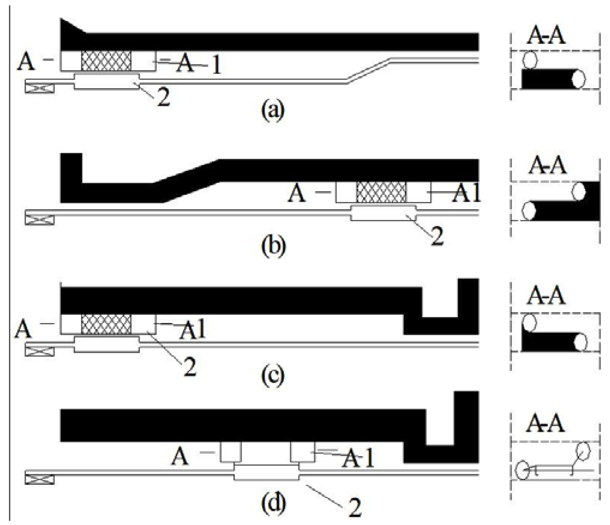
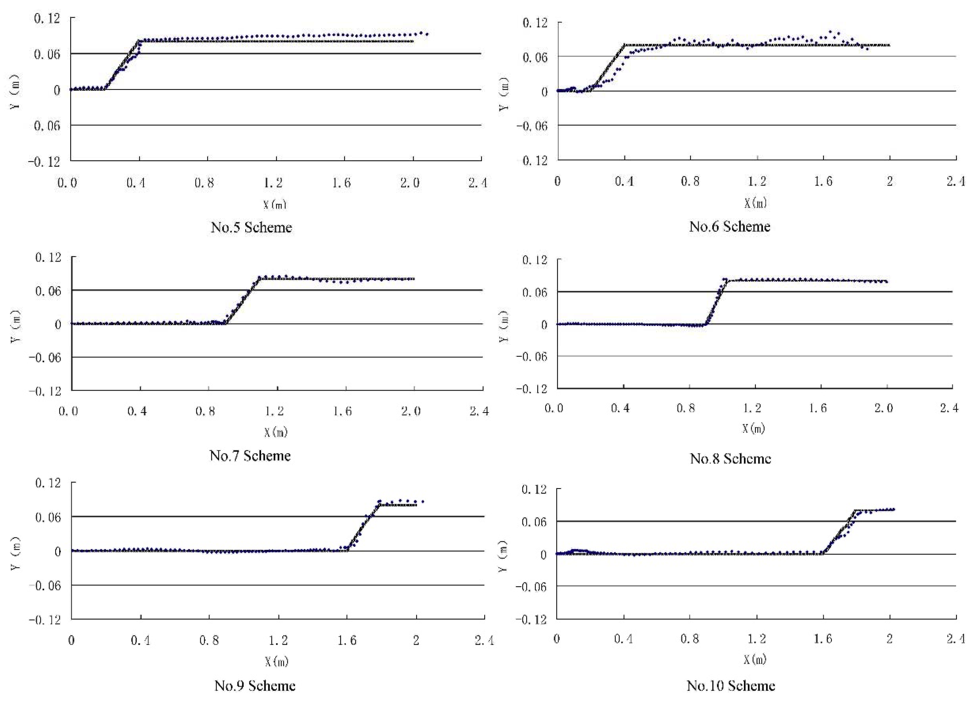
4.2. Inclined-Sumping Running Positioning Experiments

According to different running times and trajectories, six different experimental schemes are designed (see Table 3), and the sumping length is 0.2 m.

4.2.1. Identification of the Curved Section

Identification of the curved section of the scraper conveyor is the key to accurate positioning of the shearer. It is mainly determined by analyzing the output signal of the gyroscope. Both the angular velocity curve directly output by the gyroscope and the heading angle curve obtained after compensation in Schemes 5–10 are shown in Figure 9.
The angular velocity curve output by the gyroscope shows that, when the shearer moves in a straight line, the output signal of the gyroscope fluctuates around zero, the fluctuation range is small, and the overall change trend is also small. When the shearer enters the curved section, the output signal is significantly increased, which is obviously different from the signal when the shearer moves in a straight line. At the same time, the signal from the curved section is biased below zero first, and then biased above zero, showing obvious symmetry, which is consistent with the characteristics of the shearer sumping process. When the shearer exits the curved section, the gyroscope output signal keeps fluctuating around zero, and linear motion state characteristics are clearly reflected.
In the above six schemes, the data processing process still consists of 10-point smoothing preprocessing, zero bias compensation and Kalman filter compensation, and the heading angle curve is obtained after compensation. The change in the heading angle mainly includes three parts. The heading angle fluctuates around zero when the shearer moves in a straight line. When the shearer enters the curved section, the heading angle gradually changes to a negative number, then gradually changes to zero. Finally, the heading angle changes little and tends to be stable when the shearer moves in a straight line again. The theoretical value of the heading angle in the curved section is 5°, and the theoretical value of the heading angle at the endpoint is zero. The maximum values of the heading angles and the values of the heading angle at the endpoints of the experiments are given in Table 4.
It can be seen from Table 4 that there is an error between the heading angle measured by the gyroscope in the curved section and the theoretical value. Moreover, the errors in certain experiments are large. However, it is easy to judge whether the shearer enters the curved section via a comparison with the data result of the straight running experiment. There is also an error between the measured heading angle and the theoretical value at the endpoint, mainly because the experimental device does not use a thermostat to suppress the temperature change in the instrument; therefore, the zero bias caused by the gyroscope and the temperature variation cannot be fully compensated.

4.2.2. Analysis of Positioning Results

The positioning results of Schemes 5–10 are shown in Figure 10. The blue points represent the shearer position estimated by the positioning system, and the gray grid lines are the actual trajectories. It can be clearly seen from the figure that the estimated points can accurately reflect the trajectory of the shearer running, including straight line running, inclined-sumping running, and straight line running after sumping.
In the straight line running section, the estimated points are distributed around a straight line, reflecting the straight line running characteristics of the shearer, and the absolute value of the error is small. When the shearer is running in the curved section, the estimated points can reflect the position and angle of the turning movement. When the shearer turns, the error between the estimated points and the actual trajectory becomes larger, but the trend of the estimated points can still reflect the shape of the scraper conveyor. After the shearer exits the turning section, the error of the estimated points is larger than that of the initial straight line running section, mainly because the inertial navigation instrument fails to compensate completely.
The pulse data output from the odometer for the above six experimental schemes is given in Table 5. It can be seen from the table that the error between the measurement result of the odometer and the actual running distance is small, and thus the odometer is an effective device for measuring the running distance and has very high reliability.
Taking Schemes 5 and 6 as examples, comparing the positioning results of different running times of the same trajectory, the following rules are followed.
The longer the running time, the larger the positioning error, including the distance error and the angular offset error. The positive and negative of the distance error and the angle error are random and have nothing to do with the length of the running time. This is because the drift of the inertial instrument and the zero offset of the instrument is different after each startup or operation for a period of time. We know from other studies that the zero offset of inertial instruments will be affected by temperature and vibration [45,46], an effect which is shown by certain characteristics. But the use of threshold filtering and constant compensation cannot completely eliminate this error. Further research should be done on the filtering method of inertial instruments in future research.
From the above experiments, the following can be concluded:
  • Compared with the current shearer positioning technology, the shearer positioning system in this paper can not only accurately describe the shape of the scraper conveyor, but also provide information such as the sumping position and angle and length of the shearer and can achieve higher precision positioning of the shearer;
  • The random error of inertial navigation instruments cannot be completely eliminated. Methods to improve the accuracy of the system include the use of high-precision instruments and better data processing methods, including high-efficiency filtering techniques and map-matching algorithms;
  • The positioning accuracy of the inertial navigation instrument is related to the system running time. Periodic correction of the positioning data by the odometer can reduce the influence of time on the system. Initial calibration of the instrument can be performed when the shearer starts running, and the high-precision inertial navigation instrument can achieve the above function. Moreover, the odometer accumulates little error over time; therefore, the navigation data can be corrected by the odometer to achieve higher precision shearer positioning.

5. Conclusions

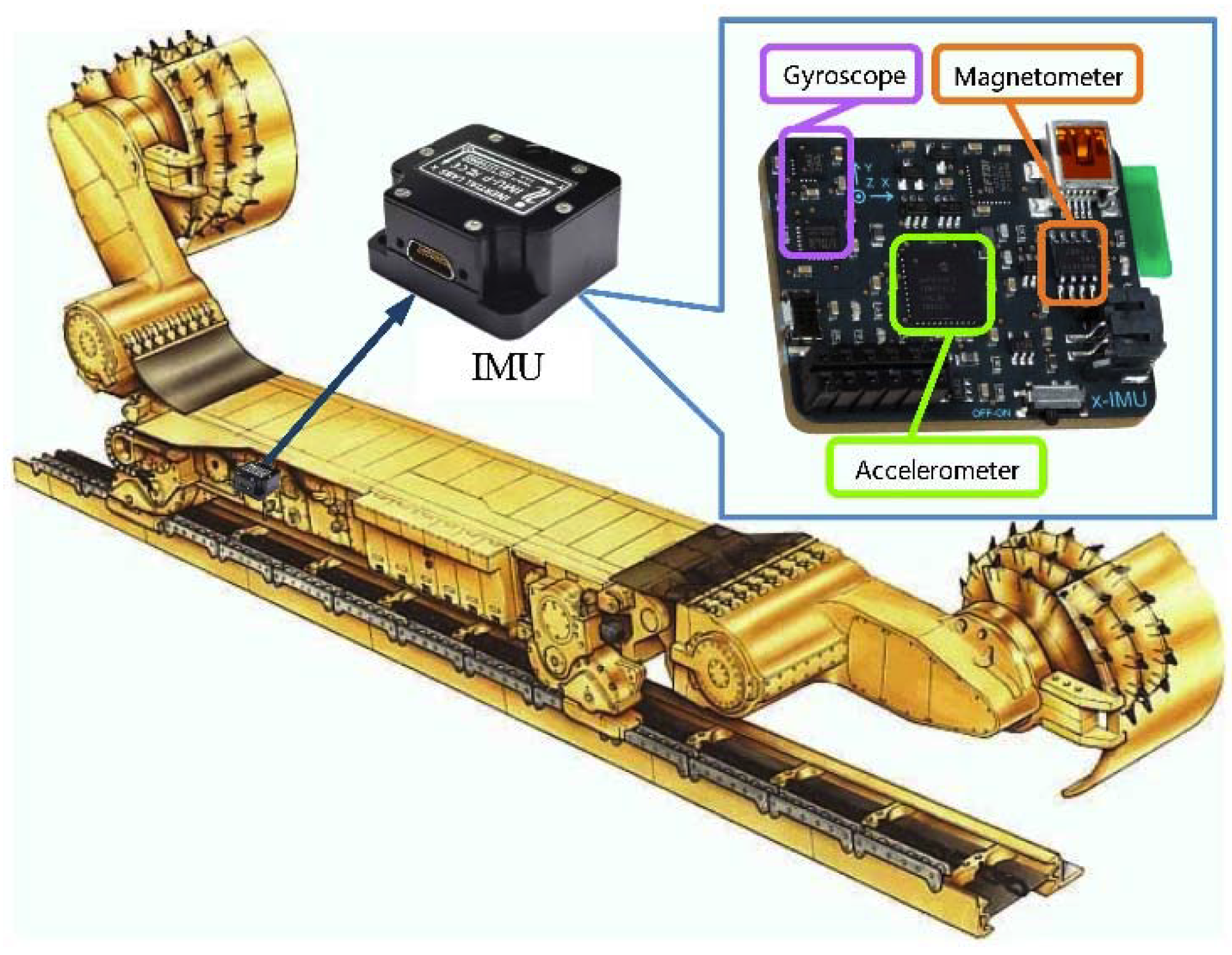
  • Based on strapdown inertial navigation technology, we analyzed the movement characteristics of the shearer on the working face, and we used inertial navigation instruments such as gyroscopes and accelerometers and the dead reckoning principle to propose a shearer positioning system on a fully mechanized working face;
  • In the shearer positioning experiments, the positioning system can accurately reflect the trajectory of the shearer running, including straight line running, inclined-sumping running, and straight line running after sumping. The experiments also show that the shearer positioning system based on SINS is indeed a very accurate shearer positioning technology;
  • To improve the positioning accuracy of the shearer positioning system and meet long-term positioning requirements, high-precision instruments and better data processing methods, including high-efficiency filtering technology and map-matching algorithms, can be used or an odometer can be used to correct the navigation data.

6. Limitations

  • Compared to an actual operating longwall operation (e.g., 200–400 m for 50–70 min), scale (2 m) and time duration (<120 s) of the experimental evaluation is indeed very small. This also leads to the fact that the experimental results may not reflect the actual situation very accurately. In the future, field experiments will be carried out in the coal mine to verify the conclusions in this paper;
  • Compared with existing commercially available solutions, such as Longwall Automation Steering Committee (LASC), Commonwealth Scientific and Industrial Research Organisation (CSIRO), Advanced Shearer Automation (ASA), Joy Global (JOY), etc., those listed may be better than the solutions in this article in terms of accuracy. However, it is well known that the SINS instruments can be used in military weapons, such as missiles, fighter jets and other weapons. An embargo has been imposed upon advanced SINS instruments in China. Even if there are SINS instruments that can be used in China, there are very strict restrictions on their use. On the other hand, the existing commercially available solutions are still too expensive and most coal mines in China cannot afford it. In the event that China cannot obtain advanced SINS instruments, it can look to improve the SINS accuracy based on algorithms, experiments and other aspects. We hope readers can understand the limitations of China’s scientific research in this regard, and also eagerly hope this article will attract the attention of relevant researchers around the world, and to obtain help and guidance from them to improve the theoretical and technical research of shearer positioning in China.

Author Contributions

Conceptualization, G.W. and X.F.; validation, G.W., X.F. and L.Z.; formal analysis, M.L. and J.L.; investigation, G.W., X.F. and Z.Q.; data curation, M.L., J.L. and Z.Q.; writing—original draft preparation, G.W. and X.F.; writing—review and editing, G.W. and L.Z.; supervision, X.F.; funding acquisition, X.F. All authors have read and agreed to the published version of the manuscript.

Funding

This research was funded by National Natural Science Foundation of China, grant number 51874276.

Acknowledgments

Financial support for this study was provided by the National Natural Science Foundation of China (No. 51874276). The authors gratefully acknowledge the financial support of the above organization.

Conflicts of Interest

The authors declare no conflict of interest.

References

  1. Jinhua, W.; Zenghua, H. The recent technological development of intelligent mining in China. Engineering 2017, 3, 439–444. [Google Scholar]
  2. Ge, S. Key Technology of Intelligent Coal Mining Equipment. Coal Sci. Technol. 2014, 42, 7–11. [Google Scholar]
  3. Wang, J.; Huang, Z. Innovation and Development of Intelligent Coal Mining Science and Technology in China. Coal Sci. Technol. 2014, 42, 1–6. [Google Scholar]
  4. Wang, G.; Zhang, D. Innovation practice and development prospect of intelligent fully mechanized technology for coal mining. J. China Univ. Min. Technol. 2018, 47, 459–467. [Google Scholar]
  5. Robert, R.; Rahinul, H. Augmenting GPS with Geolocated Fiducials to Improve Accuracy for Mobile Robot Applications. Appl. Sci. 2020, 10, 146. [Google Scholar] [CrossRef] [Green Version]
  6. Fang, X.; Zhao, J.; Hu, Y. Tests and error analysis of a self-positioning shearer operating at a manless working face. Min. Sci. Technol. 2010, 20, 53–58. [Google Scholar] [CrossRef]
  7. Wang, G. New development of longwall mining equipment based on automation and intelligent technology for thin seam coal. J. Coal Sci. Eng. 2013, 19, 97–103. [Google Scholar] [CrossRef]
  8. Zhang, B.; Fang, X.; Zou, Y.; Yu, R.; Cheng, Y. Auto-positioning system of shearer operating on manless working face based on gyroscope and odometer. Min. Process. Equip. 2010, 38, 10–13. [Google Scholar] [CrossRef]
  9. Reid, D.C.; Dunn, M.T.; Reid, P.B.; Ralston, J.C. A practical inertial navigation solution for continuous miner automation. In Proceedings of the 12th Coal Operators Conference, Univ Wollongong, Wollongong, Australia, 16–17 February 2012; pp. 115–120. [Google Scholar]
  10. Xinqiu, F.; Jie, H.; Bin, Z.; Minjiang, G. Self-positioning system of the shearer in unmanned workface. J. Xi’an Univ. Sci. Technol. 2008, 28, 349–353. [Google Scholar]
  11. Reid, D.C.; Hainsworth, D.W.; Ralston, J.C.; McPhee, R.J. Shearer guidance: A major advance in longwall mining. In Proceedings of the 4th International Conference on Field and Service Robotics, Mt Fuji, Japan, 14–16 July 2003. [Google Scholar]
  12. Zhang, X.; Zhang, P.; Meng, G.; Zhang, X. Development of on time monitoring and measuring system and visualized platform for coal cutting performances of coal shearer. Coal Eng. 2008, 2008, 101–103. [Google Scholar]
  13. Pytka, J.; Budzynski, P.; Jozwik, J.; Michalowska, J.; Tofil, A.; Lyszczyk, T.; Blazejczak, D. Application of GNSS/INS and an Optical Sensor for Determining Airplane Takeoff and Landing Performance on a Grassy Airfield. Sensors 2019, 19, 5492. [Google Scholar] [CrossRef] [PubMed] [Green Version]
  14. Hai, Y.; Wei, L.; Chengming, L.; Jinyao, Z.; Zhuoyin, S. Research on error compensation property of strapdown inertial navigation system using dynamic model of shearer. IEEE Access 2016, 4, 2045–2055. [Google Scholar]
  15. Shixin, L.; Fengrong, H.; Shiqian, Q.; Chaonan, F. SINS/Odometer integrated navigation method based on adaptive strong tracking filter. J. Chin. Inert. Technol. 2018, 26, 156–161. [Google Scholar]
  16. Hongsong, Z.; Lingjuan, M.; Jun, S. High accuracy algorithm for SINS/Odometer integrated navigation system. Acta Armamentarii 2014, 35, 433–440. [Google Scholar]
  17. Xiaoyue, Z.; Gongliu, Y.; Chunxi, Z. Integrated navigation method for SINS and odometer. J. Beijing Univ. Aeronaut. Astronaut. 2013, 39, 922–926. [Google Scholar]
  18. Yang, H.; Li, W.; Chengming, L.; Mengbao, F.; Baohua, Y. Experimental study on position and attitude technique for shearer using SINS measurement. J. China Coal Soc. 2014, 39, 2550–2556. [Google Scholar]
  19. Qigao, F.; Wei, L.; Chengming, L. Error Analysis and Reduction for Shearer Positioning using the Strapdown Inertial Navigation System. Int. J. Comput. Sci. Issues 2012, 9, 49–54. [Google Scholar]
  20. Xin, Z.; Zhongbin, W.; Chao, T.; Rui, J.; Xinhua, L. A novel approach for shearer memory cutting based on fuzzy optimization method. Adv. Mech. Eng. 2013, 1, 1–10. [Google Scholar]
  21. Dolipski, M.; Jaszczuk, M.; Cheluszka, P.; Sobota, P.; Kusak, E.; Kurek, M. Dynamic model of a Shearer’s cutting system. In Proceedings of the 9th International Symposium on Mine Planning Equipment Selection, Athens, Greece, 6–9 November 2000; pp. 541–546. [Google Scholar]
  22. Bo, W.; Qian, R.; Zhihong, D.; Mengyin, F. A self-calibration method for nonorthogonal angles between gimbals of rotational inertial navigation system. IEEE Trans. Ind. Electron. 2015, 62, 2353–2362. [Google Scholar]
  23. Feng, Q.; Xingqun, Z.; Lei, Z. Performance assessment of a low-cost inertial measurement unit based ultra-tight global navigation satellite system/inertial navigation system integration for high dynamic applications. IET Radar Sonar Navig. 2014, 8, 828–836. [Google Scholar]
  24. Bin, Z.; Jiangfeng, Y. Vibration analysis of base structure on SINS using PZT actuators. Turk. Electr. Eng. Comput. Sci. 2012, 20, 901–913. [Google Scholar]
  25. Paul, S. Coning algorithm design by explicit frequency shaping. J. Guid. Control Dyn. 2010, 33, 1123–1132. [Google Scholar]
  26. Mario, I. Optimal sculling and coning algorithms for analog-sensor systems. J. Guid. Control Dyn. 2012, 35, 851–860. [Google Scholar]
  27. John, B. A new mathematical formulation for strapdown inertial navigation. IEEE Trans. Aerosp. Electron. Syst. 1971, AES-7, 61–66. [Google Scholar]
  28. Oleg, S. Applied Inertial Navigation: Problems and Solutions; BMSTU Press: Moscow, Russia, 2004. [Google Scholar]
  29. Chul Woo, K.; Nam Ik, C.; Chan Gook, P. Approach to direct coning/sculling error compensation based on the sinusoidal modelling of IMU signal. IET Radar Sonar Navig. 2013, 7, 527–534. [Google Scholar]
  30. Jizhou, L.; Pin, L.; Jianye, L.; Bin, J. Noncommutativity error analysis of strapdown inertial navigation system under the vibration in UAVs. Int. J. Adv. Robot. Syst. 2012, 9, 1–8. [Google Scholar]
  31. Qigao, F.; Wei, L.; Yuqiao, W.; Xuefeng, Y. A shearer dynamic positioning method using strap down inertial navigation. J. China Coal Soc. 2011, 36, 1758–1761. [Google Scholar]
  32. Hai, Y.; Tao, L.; Wei, L.; Li, L.; Yue, R.; ChengMing, L. A Stable SINS/UWB Integrated Positioning Method of Shearer Based on the Multi Model Intelligent Switching Algorithm. IEEE Access 2019, 7, 29128–29138. [Google Scholar]
  33. Nikitenko, M.S.; Kizilov, S.A.; Kuleshov, V.K. Functional schemes of automated and robotic control of equipment in longwall top coal caving. In Proceedings of the Conference on Challenges for Development in Mining Science and Mining Industry, Russian Academy of Sciences, Siberian Branch, Inst Min, Novosibirsk, Russia, 1–5 October 2018. [Google Scholar]
  34. Yaping, J.; Zhipeng, X.; Zeyin, Z.; Xinggao, L. A novel shearer cutting pattern recognition model with chaotic gravitational search optimization. Measurement 2019, 144, 225–233. [Google Scholar]
  35. Post, M.A.; Bianco, A.; Yan, X.T. Autonomous Navigation with Open Software Platform for Field Robots. In Proceedings of the 14th International Conference on Informatics in Control, Automation and Robotics (ICINCO), Madrid, Spain, 26–28 July 2017. [Google Scholar]
  36. Yong, J.; Suilao, L.; Yongyuan, Q.; Richeng, C. Error analysis and compensation of MEMS rotation modulation inertial navigation system. IEEE Sens. J. 2018, 18, 2023–2030. [Google Scholar] [CrossRef]
  37. Gustaysson, A. An Efficient Approach for Detecting Moving Objects and Deriving Their Positions and Velocities. In Proceedings of the Computer Vision Conference (CVC), Las Vegas, NV, USA, 25–26 April 2019. [Google Scholar]
  38. Bo, L.; Yunpei, L.; Quanle, Z. Determination of working resistance based on movement type of the first subordinate key stratum in a fully mechanized face with large mining height. Energy Sci. Eng. 2019, 7, 777–798. [Google Scholar]
  39. Markiewicz, J.; Abratkiewicz, K.; Gromek, A.; Samczynski, W.; Gromek, D. Geometrical Matching of SAR and Optical Images Utilizing ASIFT Features for SAR-based Navigation Aided Systems. Sensors 2019, 19, 5500. [Google Scholar] [CrossRef] [PubMed] [Green Version]
  40. Michal, R.; Matej, H. Dead reckoning in a dynamic quadruped robot: Inertial navigation system aided by a legged odometer. In Proceedings of the 2011 IEEE International Conference on Robotics and Automation, Shanghai, China, 9–13 May 2011. [Google Scholar]
  41. Lubin, C.; Hongyang, H.; Fangjun, Q. In-Motion Initial Alignment for Odometer-Aided Strapdown Inertial Navigation System Based on Attitude Estimation. IEEE Sens. J. 2017, 17, 766–773. [Google Scholar]
  42. Valmorbida, A.; Mazzucato, M.; Pertile, M. Calibration procedures of a vision-based system for relative motion estimation between satellites flying in proximity. Measurement 2020, 151, 107161. [Google Scholar] [CrossRef]
  43. Yuming, C.; Wei, L.; Hai, Y.; Ting, X. Research on the Compensation Strategy of the Initial Alignment of the SINS Based on the Dynamic Model of the Shearer. IEEE Access 2019, 7, 36736–36747. [Google Scholar]
  44. Yuming, C.; Wei, L.; Gaifang, X.; Hai, Y.; Ting, X. An Improved Strong Tracking Kalman Filter Algorithm for the Initial Alignment of the Shearer. Complexity 2019. [Google Scholar] [CrossRef]
  45. Honglu, H.; Guangyao, L.; Yuan, L. Temperature Characteristic and Compensation of FOG Zero Bias Drift. Process Autom. Instrum. 2019, 40, 59–63, 68. [Google Scholar]
  46. Siying, G.; Jiangning, X.; Feng, L.; Hongyang, H. Modeling and compensation algorithm of FOG temperature drift with optimized BP neural network. J. Chin. Inert. Technol. 2016, 24, 93–97. [Google Scholar]
Figure 1. Equipment layout of a typical fully mechanized mining face; (a) front view; (b) top view.
Applsci 10 02176 g001
Figure 2. Shearer positioning system based on strapdown inertial navigation system (SINS).
Applsci 10 02176 g002
Figure 3. Orientation relationship between the carrier coordinate system and the geographic coordinate system.
Applsci 10 02176 g003
Figure 4. Principle of the shearer positioning system based on SINS.
Applsci 10 02176 g004
Figure 5. Motion characteristics of the shearer: (a) the shearer is at the end of the working face, the left drum is on the top, the right drum is at the bottom, and the scraper conveyor is in a bent state; (b) the shearer is inclined-sumping coal cutting, the left drum is at the bottom, the right drum is on the top, and the scraper conveyor is in a straight state; (c) the shearer returns to the end of the working face, the left drum is on the top, the right drum is at the bottom, and the scraper conveyor is in a straight state; (d) the shearer keeps cutting coal and runs towards the other end of the working face, the left drum is at the bottom, the right drum is on the top.
Applsci 10 02176 g005
Figure 6. Motion path of the shearer: (a) straight motion path; (b) bending motion path with the bend in the middle of the path; (c) bending motion path with the bend in the end of the path; (d) bending motion path with the bend in the other end of the path.
Applsci 10 02176 g006
Figure 7. Comparison of the shearer coordinate distribution obtained by original data and error compensation.
Applsci 10 02176 g007
Figure 8. Map matching results at different runtimes.
Applsci 10 02176 g008
Figure 9. Angular velocity curves and the heading angle curves after compensation.
Applsci 10 02176 g009
Figure 10. Results of the inclined-sumping running positioning experiments.
Applsci 10 02176 g010
Table 1. Pulse data output from the Hall sensor.
SchemeNumber of SignalsRunning Distance (cm)Displacement Error (cm)
No. 1601198.151.85
No. 2604199.140.86
No. 3603198.811.19
No. 4603198.811.19
Average value602.75198.731.27
Table 2. Error statistics from the straight line running positioning experiment.
SchemeEndpoint CoordinatesRunning Distance Error (cm)Angle Error (°)
No. 1(2.03,−0.01)3−0.04
No. 2(1.89,−0.01)11−0.25
No. 3(2.04,0.01)40.02
No. 4(1.95,−0.01)5−0.03
Average value5.80.085
Table 3. Test scheme design of the shearer feeding operation.
SchemeSumping Position (m)Running Time (s)
No. 50.260
No. 60.2120
No. 70.960
No. 80.9120
No. 91.660
No. 101.6120
Table 4. Data statistics for the heading angle.
SchemeHeading Angle in Curved Section (°)Angle Error in Curved Section (°)Heading Angle at the Endpoint (°)Angle Error at the Endpoint (°)
No. 5−4.960.04−0.230.23
No. 6−4.490.51−2.822.82
No. 7−4.530.471.761.76
No. 8−3.621.38−0.550.55
No. 9−3.531.47−1.131.13
No. 10−4.940.06−1.661.66
Average value0.6551.35
Table 5. Pulse data output from the Hall sensor.
SchemeNumber of SignalsRunning Distance (cm)Displacement Error (cm)
No. 5605199.470.53
No. 6604199.140.86
No. 7604199.140.86
No. 8605199.470.53
No. 9605199.470.53
No. 10604199.140.86
Average value604.5199.3050.695

