Abstract
The need for building protection against blast loads is a crucial issue nowadays due to the escalating threat of terrorist attacks, which affect people’s lives and critical structures. Consequently, design of protective panels to segregate building façades from the effect of a nearby explosion is required. Such design mainly depends on the ability of protective panels to mitigate and diffract the blast wave before reaching building façades. Five protective panel models with different designs, referred to as the Combined Protection System (CPS), are introduced in this paper. The main objective of this research was to achieve a design that could sustain a blast load with minimum plastic deformations. The introduced CPS designs included two steel plates linked by connector plates. The CPS dimensions were 3 m × 3 m × 0.35 m, representing length, width, and height, respectively. After that, the successful panel design was supported by placing these panels onto a masonry wall in different configurations. The protective panels were tested against 50 kg of trinitrotoluene (TNT) with a standoff distance of one meter. The final run of the optimum model was carried out using a blast load equivalent to 500 kg of TNT. The air–structure interactions were simulated using finite element analysis software called “ANSYS AUTODYN”, where the deformation of the panel was the governing parameter to evaluate the behavior of different designs. The analysis showed minimum deformation of the CPS design with vertical and horizontal connecting plates in a masonry wall distanced at 500 mm from the panel. However, the other designs showed promising results, which could make them suitable for critical structural protection on different scales.
1. Introduction
Blast loads have gained attention in recent years due to the large number of deliberate events. Thus, the protection of significant and critical structures, such as governmental buildings and airports, against extreme loads, such as high velocity impacts and explosions, has become a crucial issue. Consequently, the development of new technologies for protecting such structures against blast loads has been of great interest, not only for military applications but also for civilian purposes. The threat from an explosion is defined by the standoff distance and the charge quantity.
The techniques for protection against explosion hazards have attracted some recent attention [1,2,3,4,5,6,7,8,9,10,11,12,13,14,15,16]. Mana [17] studied the effects of an explosion on a building with and without a soil barrier. Moreover, researchers successfully reduced the effect of blast loading on building foundations by utilizing advanced material casts along with ultra-high performance concrete materials [18,19]. A study of the protection of containers was conducted by Elshafey, M.M et al. [20,21], introducing a suppressive shield container to transport hazardous materials safely on Canadian roads. Ehasni et al. [22] used composite materials for protection against an explosive charge of 100 kg of trinitrotoluene TNT. However, the cost of using composite materials was found to be too expensive and is not applicable for all buildings. Langdon et al. [23] evaluated the effect of material properties on the dynamic response of plates subjected to air explosions. Furthermore, McDonald et al. [24] experimentally investigated the dynamic response of four high-strength and armor-grade steels to blast load, in terms of deformation resistance and rupture threshold at different standoff distances. Additionally, Guangyong et al. [25] studied the effects of introducing face-sheet materials and configurations on the blast resistance of sandwich-panel structures. Additionally, Jacob et al. [26] studied the relationship between the responses of circular plates subjected to different blast loads and standoff distances. The results illustrated that the standoff distance influenced the type of loading condition applied to a structure. Mehreganian et al. [27] analytically investigated the dynamic responses of thin square plates with various boundary conditions subjected to a blast load. Zong et al. [28] investigated the mitigation capabilities of using fence walls for blast wave diffraction. The results illustrated that the fence walls could significantly reduce the peak blast pressure and impulse. Xia et al. [29] numerically studied the protective performance of metallic foam cladding on reinforced concrete slabs. Wu and Sheikh [30] investigated the abilities of metallic foam cladding to protect reinforced concrete slabs against air explosions. Furthermore, Palta et al. [31] investigated the dynamic responses of monolithic steel plates, multilayer steel plates, and hybrid plates constructed from steel and Kevlar layers against a blast load. Fallon et al. [32] numerically studied the fluid–structure interaction effect on a coated concrete slab subjected to blast loading. Furthermore, the amount of explosives was determined by knowing the incident pressure peak value, while the negative pressure was determined from the pressure after decay [33]. Additionally, Cai et al. [34] investigated the dynamic performance of multilayered hybrid aluminum foam and Ultra High Molecular Weight PolyEthylene (UHMWPE) laminates core sandwich panels subjected to air blast. The effects of foam core gradation and the utilization of UHMWPE laminates on blast mitigation performance were studied. The results revealed that deploying the UHMWPE laminate as a first core layer helped in decreasing the front face velocity. Liang et al. [35] studied the dynamic response of two-layer graded aluminum foam to blast loading. Cheng et al. [36] numerically studied polyvinyl chloride (PVC) foam-filled corrugated core sandwich panels subjected to an air explosion using ANSYS AUTODYN. Yazici et al. [37] evaluated the dynamic responses of sandwich-panel structures subjected to blast loading. The results revealed that the deflections were reduced by approximately 50%, and at the same time the weight of the panel was decreased by 2.3%. Xue and Hutchinson [38] demonstrated that the sandwich beam could withstand a higher blast load than the solid beam with the same mass and material. Zhang et al. [39] investigated the dynamic responses of corrugated sandwich plates with different core arrangements to maximize the mitigation of blast effects on the structures. Abdel Wahab et al. [40] presented a mitigation system to protect the substructures of military vehicles against blast loading by using V- shape elements. Hussein et al. [41] studied the effects of blast loads using a thin oriented strand board (OSB) cantilever wall. It was found that the OSB reduced the blast pressure by 20%.
Previous studies have presented the mitigation performance of steel barriers against blast load. It is clear that the barriers attained various values of plastic deformation without reaching complete failure. Thus, more research is needed to enhance the design of barriers to withstand a blast load while reducing the plastic deformation values. As a result, this paper introduces an improved steel protective panel design that could sustain a blast load with minimum plastic deformation and avert any failure. This panel design includes a modified structural design. The modifications include reinforcement techniques using shear connectors and horizontal and vertical walls.
2. Pressures on the Structural Surfaces
The blast load is characterized by the instantaneous release of an enormous amount of energy, and depends on the explosive materials and the basis of their physical state [42]. Explosions are classified as far-range explosions when the offset distance is equal to or greater than 1.2 m/kg1/3; and are classified as near-range explosions when the offset distance is less than 1.2 m/kg1/3. Figure 1 represents a typical pressure versus time plot of a blast wave. The blast wave is characterized by a sudden increase in incident pressure to a certain peak value, and the subsequent decay in the atmospheric pressure (positive phase). After that, the incident pressure decays further underneath the ambient atmospheric pressure producing negative phase pressure. The pressure at any instant of time is defined by the modified Friedlander’s equation, as presented in Equation (1)
where, P(t) is the incident overpressure at any time instant; P0 is the ambient pressure; Pso+ and Pso− are the peak positive incident overpressure and the peak negative incident under-pressure, respectively; tpos and tneg are the positive and the negative phase durations for the incident blast wave, respectively; ta is the arrival time; and θ is the decay parameter of the wave. Friedlander equation can be used for the positive phase . The peak side-on overpressure is presented in Equation (2) [43]
where K1 is a constant depending on the quantity of the explosive charge as in [43]. The scaled distance is represented as , where the variables R and W refer to the distance from the center of a spherical charge and the charge mass of equivalent TNT, respectively.
Figure 1.
Pressure vs. time plot for blast wave.
3. Mathematical Model and Model Hypothesis
Protective panel models consist of two steel plates joined with connectors. The models introduced in this paper are called the Combined Protection System (CPS), which is an extension of a previous model for a protective panel investigated in [44]. The panel design used in this study consisted of two steel plates, each 20 mm in thickness with a steel yield stress of 4.0 × 10⁵ kPa. The panel dimensions were 3 m tall, 3 m wide, and 350 mm thick. Moreover, the panel was supported at the bottom due to the limitations of deformation in the middle; hence, the bottom fixed support helped in reducing the deformation in the middle of the panel. The parameters were adopted from [44]. Furthermore, the effective charge weight was 50 kg of TNT. The standoff distance between the explosive charge and panels was set to 1 m. The ANSYS AUTODYN finite element analysis package was deployed to simulate the blast wave propagation, due to its ability to study air–structure interactions. The material properties for the TNT and air were retrieved from the standard AUTODYN library. The modeling of the air was carried out using 3D Euler equations, while the explosive charge was typically modeled using the Jones Wilkens Lee (JWL) equation of state, which can be written as Equation (3) [28,45,46]
where P denotes the hydrostatic pressure, v denotes the specific volume, and e denotes the specific internal energy. C1, r1, C2, r2, and w are the material constants. The values of constants C1, r1, C2, r2, and w for many common explosives have been previously determined from dynamic experiments. The values of the constants for TNT explosives are available in AUTODYN as shown in Table 1 [28,46,47].

Table 1.
TNT explosive parameters.
In addition, the air is modeled by an ideal gas equation of state, which can be expressed as in Equation (4)
where, γ denotes the heat specific ratio and ρ denotes the density. The standard constants of air were taken from AUTODYN material library, that is, air density, where ρ = 1.225 kg/m3 and γ = 1.4. The air initial internal energy was assumed to be 2.068 × 10⁵ kJ/kg [46].
The material of the steel panel was selected from the ANSYS library. Additionally, the linear equation of state and strength model was applied. The yield stress of the steel panel was assumed to be 4 × 10⁸ (Pa). The solver used for steel plates was the shell element. The air element was modeled with dimensions of 4 m, 3 m, and 3 m, representing length, width, and height, respectively. Moreover, movable gauges to measure deformation were added, where the critical gauge position was placed at the mid-point of the panel. During the analysis there was a raised governing variable paradox either pressure or deformation to be considered as governing variable as clarified in Fekry, M. et al. [44]. Furthermore, deformation was selected to be the governing value. Eventually, the boundary condition was set as fixed free from the lower cross-section of the panel. Figure 2 illustrates the model setup. For accuracy, the model validation was based on the previous work of the authors of [44]. By comparing the results of the verification model and the reference model it was found that the correlation of the results was very strong. The displacement peak value in the reference model was 82 mm and was 79 mm in the verification model [44].
Figure 2.
Model setup.
4. Results and Discussion
4.1. CPS 3
Horizontal and vertical plates were used in a joining method, where the vertical position distance was 750 mm from the edge and the horizontal distance was 500 mm equally spaced. The horizontal and vertical plates had a thickness of 12 mm. Figure 3 represents the orientation of horizontal and vertical plates inside the panel. The mixed orientation of the joining plates improved the distribution of the load on the front and rear plates; thus, deformation was distributed along the plates. Consequently, the maximum deformation was reduced to 20 mm and occurred at 13 milliseconds. The graph of deformation versus time showed a significant reduction in deformation and achieved promising results, as shown in Figure 4. Figure 5 shows the location of the maximum deformation located in the middle of panel. The vertical plates increased the stiffness in the direction of loading due to the increase in inertia of the panel. Finally, the mixed oriented connectors improved the stiffness of the structure in main stress directions. Plastic deformation in this model varied in distribution between the front, rear, and stiffener plates. Deformation in the front plate recorded a wide plastic region. However, plastic deformation in the rear plate was included in small regions. Furthermore, the deformation in vertical connecting plates was plastic deformation with small elastic regions. The lower horizontal connecting plates achieved a larger plastic deformation region compared to the upper plates. This is because of the proximity of lower plate to the explosive charge. In conclusion, the contribution of the vertical plates was significant. Comparison between the deformation plots for the front, rear, and connector plates is shown in Figure 6, Figure 7 and Figure 8. Where the green color represents an elastic region and the light blue color represents a plastic region.
Figure 3.
Orientation of horizontal and vertical plates inside the panel for Combined Protection System (CPS) 3.
Figure 4.
Time history displacement curve for CPS 3.
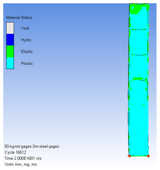
Figure 5.
Location of the maximum deformation located at the panel middle for CPS 3.
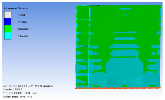
Figure 6.
Plastic deformation region in front plate for CPS 3.
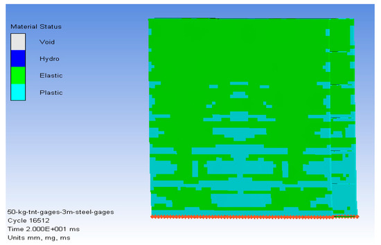
Figure 7.
Plastic deformation region in rear plate for CPS 3.
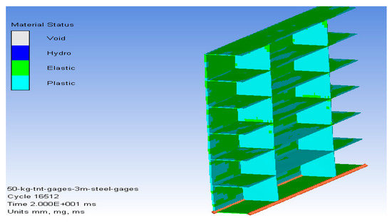
Figure 8.
Plastic deformation region in connector plates for CPS 3.
4.2. CPS 4
The number of vertical plates was increased to four, equally spaced at 1000 mm, while the number of horizontal plates was kept the same as in the previous model. Figure 9 represents the orientation of horizontal and vertical plates inside the panel. The new panel design improved the deformation distribution, while reducing the regions of plastic deformation in all plates. In addition, the maximum deformation was reduced significantly to 16 mm, occurring 9 milliseconds before the panel started relieving the load. The vertical plates achieved a smaller plastic region compared to the previous model. The design cost of this model would be higher than the previous model, but it withstood the blast load with less damage and without failure. Furthermore, such panels would be able to sustain sequential blast waves, in case of several attacks occurring concurrently. Finally, the CPS results achieved the main goal, which was clearly observed in the deformation graph shown in Figure 10. Figure 11 shows the location of the maximum deformation at the middle of the panel. Moreover, the plastic deformation regions of the rear, front, vertical, and horizontal plates showed promising results matching the aims of the researcher, as shown in Figure 12, Figure 13 and Figure 14.
Figure 9.
Orientation of horizontal and vertical plates inside the panel for CPS 4.
Figure 10.
Time displacement curve for CPS 4.
Figure 11.
Location of the maximum deformation, located at the panel middle for CPS 4.
Figure 12.
Plastic deformation region in front plate for CPS 4.
Figure 13.
Plastic deformation region in rear plate for CPS 4.
Figure 14.
Plastic deformation region in connector plates for CPS 4.
4.3. CPS 4 and Masonry Wall with No Distance between Them
The masonry wall used in the model consisted of standard small bricks placed in the wide direction. Cement mortar joined the brick with each other. The wall dimensions were concurrent with the panel dimensions. The panel was separated from the wall by zero distance; it was totally in contact with the front plate. Boundary condition selected for the wall represented a hinged wall, as shown in Figure 15. Reasons behind the use of a masonry wall include two main points. Firstly for security reasons; in most cases, the panel would be placed on the inner side of the premises’ fence wall to work as the main protective component without being visible from the outside. Secondly, a masonry wall would fail once the charge was detonated, which would reduce the intensity of the blast wave before hitting the front panel plates. Consequently, the deformation after adding the masonry wall was reduced significantly, recording a maximum deformation of 13 mm. Figure 16 shows the maximum deformation, which occurred at 11 milliseconds. Furthermore, the deformation first occurred in the mortar of the wall; after that, bricks start failing. Figure 17 shows that the maximum deformation occurred in CPS4 at the end of analysis and failure of the masonry wall. Moreover, the plastic deformation regions of the rear, front, vertical, and horizontal plates were lower than CPS4 because the masonry wall consumed part of blast wave, as shown in Figure 18, Figure 19 and Figure 20.
Figure 15.
Model setup for CPS 4 and masonry wall with no distance.
Figure 16.
Time displacement curve of CPS 4 and masonry wall with no distance.
Figure 17.
The maximum deformation for CPS 4 and wall failure.
Figure 18.
Plastic deformation region in front plate of CPS 4 and masonry wall with no distance.
Figure 19.
Plastic deformation region in rear plate for CPS 4 and masonry wall with no distance.
Figure 20.
Plastic deformation region in connector plates of CPS 4 and masonry wall with no distance.
4.4. CPS 4 and Masonry Wall with 500 mm Distance between Them
CPS 4 presumes that the panel will be installed behind a masonry wall with a distance between them equal to 500 mm. Hence, the previous model was repeated with the same conditions but with a 500 mm distance between panel and masonry wall. This distance allowed the masonry wall to absorb more energy while failing. Figure 21 shows the model setup. The blast swept the wall until hitting the panel as shown in Figure 22. This reduced the blast load effect by a significant value. Consequently, the deformation in the panel achieved near zero deformation. Deformation recorded a maximum value of 2 mm at 5 milliseconds, as shown in Figure 23. Furthermore, the plastic deformation region was obvious where the masonry wall hit the panel at the front plate. Nevertheless, the rear plate showed zero plastic region, which means that the rear plate was functioning after the blast, with no damage. So, the panel could be reversed and not changed until the second incident might happen. This would lead to cost reduction and would double the panel life cycle. However, if the explosive charge weight were doubled, the panel would have extra protection with the same setup at the time of the attack. Figure 24 and Figure 25 show the impact of the blast load on the front and the rear plates.
Figure 21.
Model setup in case of CPS 4 and masonry wall with 500 mm distance.
Figure 22.
Deformation plot of CPS 4 and masonry wall with 500 mm distance.
Figure 23.
Time displacement curve of CPS 4 and masonry wall with 500 mm distance.
Figure 24.
Plastic deformation region in front plate of CPS 4 and masonry wall with 500 mm distance.
Figure 25.
Plastic deformation region in rear plate of CPS 4 and masonry wall with 500 mm distance.
The great performance of CPS4 against the 50 kg of TNT allowed the authors to take the model to next level. The model was repeated and examined against a charge weight of 500 kg of TNT. This run helped to study the maximum bearable blast load of the panel. Astonishing results were observed, proving that the panel could protect critical buildings from a charge of up to 500 kg of TNT. Such an explosive charge would emulate a large-scale terrorist attack. Figure 26 shows the deformation versus time of the panel against 500 kg of TNT. The maximum deformation value was 160 mm, occurring at 20 ms. The plastic deformation region of the rear plate is shown in Figure 27. The failure in the masonry wall, the front plate, and the connecting plates are shown in Figure 28, Figure 29 and Figure 30, respectively.
Figure 26.
Time displacement curve due to charge weight of 500 kg of TNT.
Figure 27.
Plastic deformation region in rear plate due to charge weight of 500 of TNT.
Figure 28.
Masonry wall failure due to charge weight of 500 kg of TNT.
Figure 29.
Front plate failure due to charge weight of 500 kg of TNT.
Figure 30.
Connecting plates failure due to charge weight of 500 kg of TNT.
Following the blast wave, the masonry wall was swept until smashing the front plate; the masonry wall was totally destroyed and tore the plate at a lower section. Moreover, the horizontal plate was disintegrated from the middle at the vertical plates. Furthermore, the fragments of all the failed parts crumbled onto the rear plate, causing high plastic deformation. However, the plastic region was very large with no obvious failure occurring in the rear plate. This means that such panels could withstand a charge of up to 500 Kg of TNT. Eventually, this model proved that the CPS4 had a chance to survive a charge that is larger than moderately sized, which is rarely used in suicide attacks. In conclusion, the research aim has been achieved and validated theoretically.
5. Conclusions
Combined protection systems were investigated against various blast loads in this paper. Panel designs consisted of front and rear steel plates connected with vertical and horizontal stiffeners. Finite element simulation techniques were used to avoid the complexity and expenses of physical tests.
The investigation was simulated using the ANSYS (AUTODYN) finite elements package. The analysis parameters were consistent with the other research parameters, and reflected real cases. The results presented above ensured that all the panels would survive a blast load that would result from 50 kg of TNT without any failure. However, the differences between the various designs were the distribution of plastic deformation region and the maximum deformation values. The concept of placing a solid barrier to decrease the effect of a blast load presented many promising results.
The robust design of the panels showed great performance, not only in resisting a blast wave but also in providing protection from fragments. This will help in improving the safety and security of critical infrastructures without having such protection panels visible. The comparison of various panel designs allowed the authors to select the more robust design and examine it against a higher explosive charge quantity. This resulted in the design withstanding the extreme loading but with total failure of the front plate. With all being said, the presented designs showed outstanding blast wave mitigation capabilities. Moreover, the AUTODYN software showed great ability in studying air–structure interactions with a high-level of accuracy.
Author Contributions
E.F. and M.M.E.; methodology, E.F. and M.M.E.; software, E.F.; M.M.E.; and M.H. analyzed the data; E.F. and M.M.E.; validation, E.F.; M.M.E.; and M.H.; formal analysis, E.F. and M.M.E. investigation, A.A., E.F., M.M.E., and M.H.; resources, E.F. and M.M.E.; data curation, E.F. and M.M.E.; writing—original draft preparation, E.F., M.M.E., and M.H., writing—review and editing, E.F., and M.M.E.; supervision. All authors have read and agreed to the published version of the manuscript.
Funding
This research received no external funding.
Acknowledgments
The authors are grateful to Taif University (Taif, KSA), Military Technical College (Cairo, Egypt), the knowledge Hub Universities, and Mansoura University (Mansoura, Egypt) for providing all the required facilities to carry out the present research.
Conflicts of Interest
The authors declare no conflicts of interest.
References
- Abbas, A.; Adil, M.; Ahmad, N.; Ahmad, I. Behavior of reinforced concrete sandwiched panels (RCSPs) under blast load. Eng. Struct. 2019, 181, 476–490. [Google Scholar] [CrossRef]
- Draganić, H.; Gazić, G.; Varevac, D. Experimental investigation of design and retrofit methods for blast load mitigation—A state-of-the-art review. Eng. Struct. 2019, 190, 189–209. [Google Scholar] [CrossRef]
- Li, Z.; Chen, W.; Hao, H. Numerical study of sandwich panel with a new bi-directional Load-Self-Cancelling (LSC) core under blast loading. Thin-Walled Struct. 2018, 127, 90–101. [Google Scholar] [CrossRef]
- Helal, M.M.K.; Elsayed, F. Dynamic behavior of stiffened plates under underwater shock loading. Mater. Test. 2015, 57, 506–517. [Google Scholar] [CrossRef]
- Fathallah, E.; Qi, H.; Tong, L.; Helal, M. Numerical Simulation and Response of Stiffened Plates Subjected to Non-Contact Underwater Explosion. Adv. Mater. Sci. Eng. 2014, 2014, 752586. [Google Scholar] [CrossRef]
- Fathallah, E.; Qi, H.; Tong, L.; Helal, M. Numerical investigation of the dynamic response of optimized composite elliptical submersible pressure hull subjected to non-contact underwater explosion. Compos. Struct. 2015, 121, 121–133. [Google Scholar] [CrossRef]
- Xu, J.; Liu, J.; Gu, W.; Liu, X.; Cao, T. Shock Wave Attenuation Characteristics of Aluminum Foam Sandwich Panels Subjected to Blast Loading. Shock Vib. 2018, 2018, 2686389. [Google Scholar] [CrossRef]
- Liu, H.; Cao, Z.K.; Yao, G.C.; Luo, H.J.; Zu, G.Y. Performance of aluminum foam–steel panel sandwich composites subjected to blast loading. Mater. Des. 2013, 47, 483–488. [Google Scholar] [CrossRef]
- Wang, C.; Xu, B.; Chung Kim Yuen, S. Numerical analysis of cladding sandwich panels with tubular cores subjected to uniform blast load. Int. J. Impact Eng. 2019, 133, 103345. [Google Scholar] [CrossRef]
- Chen, D.; Jing, L.; Yang, F. Optimal design of sandwich panels with layered-gradient aluminum foam cores under air-blast loading. Compos. Part B Eng. 2019, 166, 169–186. [Google Scholar] [CrossRef]
- Helal, M.; Huang, H.; Fathallah, E.; Wang, D.; ElShafey, M.M.; Ali, M.A.E.M. Numerical Analysis and Dynamic Response of Optimized Composite Cross Elliptical Pressure Hull Subject to Non-Contact Underwater Blast Loading. Appl. Sci. 2019, 9, 3489. [Google Scholar] [CrossRef]
- Wang, Y.; Wang, H.; Cui, C.; Zhao, B. Investigating Different Grounds Effects on Shock Wave Propagation Resulting from Near-Ground Explosion. Appl. Sci. 2019, 9, 3639. [Google Scholar] [CrossRef]
- Zhou, X.Q.; Hao, H. Prediction of airblast loads on structures behind a protective barrier. Int. J. Impact Eng. 2008, 35, 363–375. [Google Scholar] [CrossRef]
- Elsayed, F.; Nagy, N.M.; Lili, T. Numerical Evaluation of Composite Plates Performance under the Effect of Underwater Explosion. In Proceedings of the 15th International Conference on Aerospace Sciences & Aviation Technology, Military Technical College, Kobry Elkobbah, Cairo, Egypt, 29 May 2013; pp. 1–15. [Google Scholar]
- Abdel Wahab, M.M.; Mazek, S.; Abada, M.M. Effect of blast wave on lightweight structure performance. J. Eng. Sci. Mil. Technol. 2017, 1, 1–6. [Google Scholar] [CrossRef]
- Alqwasmi, N.; Tarlochan, F.; Alkhatib, E.S. Study of Mild Steel Sandwich Structure Energy Absorption Performance Subjected to Localized Impulsive Loading. Materials 2020, 13, 670. [Google Scholar] [CrossRef]
- Maňas, P. The Protection of Critical Infrastructure Objects—Technical Principles. In Durability of Critical Infrastructure, Monitoring and Testing; Springer: Singapore, 2017; pp. 239–248. [Google Scholar]
- Li, J.; Wu, C.; Hao, H.; Liu, Z. Post-blast capacity of ultra-high performance concrete columns. Eng. Struct. 2017, 134, 289–302. [Google Scholar] [CrossRef]
- Wang, H.; Wu, C.; Zhang, F.; Fang, Q.; Xiang, H.; Li, P.; Li, Z.; Zhou, Y.; Zhang, Y.; Li, J. Experimental study of large-sized concrete filled steel tube columns under blast load. Constr. Build. Mater. 2017, 134, 131–141. [Google Scholar] [CrossRef]
- Elshafey, M.M.; Braimah, A.; Abd El Halim, A.O.; Contestabile, E. Aluminum Foam-Lined Suppressive Shields for Safe Transport of Explosives: Experimental Investigation. Transp. Res. Rec. 2012, 2288, 91–102. [Google Scholar] [CrossRef]
- Braimah, A.; Elshafey, M.; Halim, A.E.H.O.A.E.; Contestabile, E. Experimental Investigation of Aluminum Foam Lined Suppressive Shield Containment Vessels. Int. J. Prot. Struct. 2012, 3, 193–220. [Google Scholar] [CrossRef]
- Peña, M.E.A.C. Blast Loading Retrofit of Unreinforced Masonry Walls. Struct. Perform. Artic. 2009, 4, 16–20. [Google Scholar]
- Langdon, G.S.; Lee, W.C.; Louca, L.A. The influence of material type on the response of plates to air-blast loading. Int. J. Impact Eng. 2015, 78, 150–160. [Google Scholar] [CrossRef]
- McDonald, B.; Bornstein, H.; Langdon, G.S.; Curry, R.; Daliri, A.; Orifici, A.C. Experimental response of high strength steels to localised blast loading. Int. J. Impact Eng. 2018, 115, 106–119. [Google Scholar] [CrossRef]
- Sun, G.; Wang, E.; Zhang, J.; Li, S.; Zhang, Y.; Li, Q. Experimental study on the dynamic responses of foam sandwich panels with different facesheets and core gradients subjected to blast impulse. Int. J. Impact Eng. 2019. [Google Scholar] [CrossRef]
- Jacob, N.; Nurick, G.N.; Langdon, G.S. The effect of stand-off distance on the failure of fully clamped circular mild steel plates subjected to blast loads. Eng. Struct. 2007, 29, 2723–2736. [Google Scholar] [CrossRef]
- Mehreganian, N.; Fallah, A.S.; Louca, L.A. Inelastic dynamic response of square membranes subjected to localised blast loading. Int. J. Mech. Sci. 2018, 148, 578–595. [Google Scholar] [CrossRef]
- Zong, R.; Hao, H.; Shi, Y. Development of a New Fence Type Blast Wall for Blast Protection: Numerical Analysis. Int. J. Struct. Stab. Dyn. 2017, 17, 1–29. [Google Scholar] [CrossRef]
- Xia, Y.; Wu, C.; Zhang, F.; Li, Z.-X.; Bennett, T. Numerical Analysis of Foam-Protected RC Members under Blast Loads. Int. J. Prot. Struct. 2014, 5, 367–390. [Google Scholar] [CrossRef]
- Wu, C.; Sheikh, H. A finite element modelling to investigate the mitigation of blast effects on reinforced concrete panel using foam cladding. Int. J. Impact Eng. 2013, 55, 24–33. [Google Scholar] [CrossRef]
- Palta, E.; Gutowski, M.; Fang, H. A numerical study of steel and hybrid armor plates under ballistic impacts. Int. J. Solids Struct. 2018, 136–137, 279–294. [Google Scholar] [CrossRef]
- Fallon, C.; McShane, G.J. Fluid-structure interactions for the air blast loading of elastomer-coated concrete. Int. J. Solids Struct. 2019, 168, 138–152. [Google Scholar] [CrossRef]
- Baker, W.E. Explosions in Air; University of Texas Press: Austin, TX, USA; London, UK, 1973. [Google Scholar]
- Cai, S.; Liu, J.; Zhang, P.; Li, C.; Cheng, Y. Dynamic response of sandwich panels with multi-layered aluminum foam/UHMWPE laminate cores under air blast loading. Int. J. Impact Eng. 2020, 138, 103475. [Google Scholar] [CrossRef]
- Liang, M.; Li, X.; Lin, Y.; Zhang, K.; Lu, F. Dynamic Compressive Behaviors of Two-Layer Graded Aluminum Foams under Blast Loading. Materials 2019, 12, 1445. [Google Scholar] [CrossRef] [PubMed]
- Cheng, Y.; Zhou, T.; Wang, H.; Li, Y.; Liu, J.; Zhang, P. Numerical investigation on the dynamic response of foam-filled corrugated core sandwich panels subjected to air blast loading. J. Sandw. Struct. Mater. 2019, 21, 838–864. [Google Scholar] [CrossRef]
- Yazici, M.; Wright, J.; Bertin, D.; Shukla, A. Experimental and numerical study of foam filled corrugated core steel sandwich structures subjected to blast loading. Compos. Struct. 2014, 110, 98–109. [Google Scholar] [CrossRef]
- Xue, Z.; Hutchinson, J.W. A comparative study of impulse-resistant metal sandwich plates. Int. J. Impact Eng. 2004, 30, 1283–1305. [Google Scholar] [CrossRef]
- Zhang, L.; Hebert, R.; Wright, J.T.; Shukla, A.; Kim, J.-H. Dynamic response of corrugated sandwich steel plates with graded cores. Int. J. Impact Eng. 2014, 65, 185–194. [Google Scholar] [CrossRef]
- Abdel Wahab, M.; Mazek, S.; Abada, M.; Abdel Shafy, M. Blast hazard impact on V-shape composite panel performance. J. Eng. Sci. Mil. Technol. 2018, 2, 90–99. [Google Scholar] [CrossRef][Green Version]
- Hussein, A.; Heyliger, P.; Mahmoud, H. Blast response of a thin oriented strand board wall. Eng. Struct. 2019, 201, 109835. [Google Scholar] [CrossRef]
- Goswami, A.; Adhikary, S.D. Retrofitting materials for enhanced blast performance of Structures: Recent advancement and challenges ahead. Constr. Build. Mater. 2019, 204, 224–243. [Google Scholar] [CrossRef]
- Bulson, P.S. Explosive Loading of Engineering Structures; CRC Press: Boca Raton, FL, USA, 2002. [Google Scholar]
- Fekry, M.; Mahmoud, G.; Elshafey, M. Protective Panels Design against Blast Loads. Aust. J. Basic Appl. Sci. 2017, 11, 143–156. [Google Scholar]
- Fedorova, N.; Valger, S.; Fedorov, A. Simulation of blast action on civil structures using ANSYS Autodyn. In Proceedings of the AIP Conference Proceedings, Perm Krai, Russia, 27 June–3 July 2016; pp. 1–10. [Google Scholar]
- Zheng, C.; Kong, X.-S.; Wu, W.-G.; Xu, S.-X.; Guan, Z.-W. Experimental and numerical studies on the dynamic response of steel plates subjected to confined blast loading. Int. J. Impact Eng. 2018, 113, 144–160. [Google Scholar] [CrossRef]
- Wu, C.; Lu, Y.; Hao, H. Numerical prediction of blast-induced stress wave from large-scale underground explosion. Int. J. Numer. Anal. Methods Geomech. 2004, 28, 93–109. [Google Scholar] [CrossRef]
© 2020 by the authors. Licensee MDPI, Basel, Switzerland. This article is an open access article distributed under the terms and conditions of the Creative Commons Attribution (CC BY) license (http://creativecommons.org/licenses/by/4.0/).