Article

Experimental Study of Environmental Conditions on In-Situ Engineered Cementitious Composites-Steel Deck Interface

1
School of Transportation, Southeast University, 2 Southeast University Road, Nanjing 211189, China
2
School of Science, Nanjing University of Science and Technology, 200 Xiaolingwei, Nanjing 210094, China
*
Author to whom correspondence should be addressed.
Appl. Sci. 2020, 10(6), 2123; https://doi.org/10.3390/app10062123
Submission received: 30 August 2019 / Revised: 12 March 2020 / Accepted: 13 March 2020 / Published: 20 March 2020
(This article belongs to the Special Issue Assessing and Extending the Service Life of Bridges)

Abstract

:
In this study, engineered cementitious composite (ECC) was used as a deck paving for long-span bridges. The feasibility of using an epoxy adhesive to achieve wet-bonding between a steel deck and cast-in-place ECC was evaluated. The shear and pull-off tests were conducted to evaluate the effects of freeze-thaw cycles and hydrothermal aging on interfacial properties. The test results indicate that the interfacial strength decreases with an increase in the number of freeze-thaw cycles and the duration of hydrothermal aging. Based on an inclined shear test, a criterion for interface failure under the combined action of shear and compression is also proposed. Wet-bonding technology might promote the application of ECC in the surfacing system for orthotropic steel deck bridge and further extend the service life of a bridge structure.

1. Introduction

A bridge deck overlay is an important part of a long-span bridge. As a protective layer of deck, deck paving directly affects driving safety and comfort, and it also significantly affects the service life of the whole bridge. Asphalt concrete is widely used in orthotropic steel deck overlay, because of its good driving comfort, fast construction speed, and easy maintenance. However, negative bending moment zones are formed at the supporting positions of cross beam, longitudinal rib, and main girder web because of small and uneven support stiffness of orthotropic deck. The negative moment results in a large tensile stress and even cracking in asphalt overlay [1]. In addition, the bonding performance between steel deck and asphalt overlay is poor, thus causing distress, such as jostle and upheaval [2]. Although epoxy asphalt concrete has good performance, it is expensive and highly sensitive to ambient conditions during construction. Moreover, the preparation and construction technology of epoxy asphalt concrete are complex. To solve these problems, since the 1990s, some scholars have tried to use a cementitious overlay to improve the stiffness of a steel bridge deck and its stress state [3].
In this study, engineered cementitious composite (ECC), a typical high-ductility cementitious composite (HDCC), was used as the overlay of an orthotropic steel deck bridge. Victor C. Li first proposed the ECC design theory in the early 1990s [4]. ECC has remarkable strain-hardening and multicracking properties [5]. The ultimate tensile strain can be higher than 3%, which is approximately 300 times larger when compared to ordinary concrete, and the maximum crack width in a saturated state is usually below 100 μm [6]. The stiffness of a bridge deck system can be improved by using ECC without increasing the thickness and weight of overlay because of the high modulus of ECC. Moreover, ECC has better temperature stability, water stability, and impermeability as compared to asphalt concrete, and it also has good self-healing performance and fatigue resistance.
As for the interface connection for paving materials and bridge decks, cement-based overlay is often connected with steel deck by welding shear connectors [7,8]. However, the welding process is inconvenient and might lead to stress concentration and fatigue problems for bridges. Moreover, the maintenance of these overlays is complex and tedious [9]. Wet-bonding technology is a good alternative for overcoming those disadvantages that are caused by welding connection. As one type of adhesive bonding, wet-bonding has the advantages of a large contact area, uniform stress distribution, improvement in the stiffness of overlay structure, and easy construction. Wet-bonding technology with epoxy adhesive has evolved as a new bonding technique. In 1995, Deskovic [10] pioneered the use of wet bonding in composite beams, but delamination and peeling occurred in the interface of composite beams with wet-bonding. Canning et al. [11] compared the effects of six types of interface modes through flexural tests of composite beams. The results showed that the wet-bonding effect of epoxy resin was slightly worse than that of dry-bonding. However, wet-bonding is regarded as the most practical interface mode when considering the actual construction of new composite structures. Many experimental studies were performed to evaluate the strength of wet-bonding interface; however, the findings are quite different among the studies [12,13,14,15,16]. The main reason for this difference is attributed to the different types of resins used in the studies.
On the other hand, deck overlay is affected by various environmental factors in practical applications, and hostile environmental conditions might exist in some regions and seasons. For example, cold and dry winters characterize North China, while South China is characterized by hot and rainy summers. Therefore, freeze-thaw damage and hydrothermal aging should be considered in different climate regions [17].
Figure 1 shows the overlay structure for orthotropic steel deck bridges used in this study. Shear test and pull-off test were conducted to evaluate the effects of freeze-thaw cycles and hydrothermal aging on interfacial properties between steel deck and cast-in-place ECC. This study is a part of a long-term research effort in the design and application of ECC and wet-bonding technology in overlay systems for orthotropic steel deck bridges.

2. Materials and Experiments

2.1. Materials

Cement, fly ash, silica sand, polyvinyl alcohol (PVA) fiber, water, and water reducer were utilized to prepare ECC. Table 1 shows the chemical composition of cement and fly ash. The particle size of silica sand is 0.106–0.212 mm, and the maximum nominal size is 0.180 mm. The SiO2 content of silica sand is 98.7%, and its density is 2.66 g/cm3. Table 2 shows the properties of PVA fiber. Table 3 shows the mix proportions of ECC. A two-component epoxy adhesive was used as the epoxy binder in this study; the proportion of components A and B is 2:1. Table 4 illustrates the properties of epoxy binder. The steel plate used in this study is Q345qD, a special steel for bridges with a yield strength of 345 MPa [18]. The steel plate was sandblasted to remove the rust and sprayed with an epoxy zinc-rich paint.

2.2. Specimen Preparation

The mixing procedure for ECC is as follows: (1) Cement, fly ash, and silica sand were added to a blender and mixed at 100 rpm for 3 min. (2) Water and water reducer, which were previously dissolved in the water, were added and mixed at 100 rpm for 1 min. and then at 400 rpm for 4 min. (3) Fibers were slowly and manually added along the stirring direction and mixed at 400 rpm for 10 min.
The steel plates were coated with epoxy binder and then placed in the steel molds. Epoxy binder was cured at room temperature (20 °C) for 30 min, and ECC was then cast in steel molds, as shown in Figure 2. The specimens were demolded after 24 h and then kept in a standard curing chamber at a relative humidity of (95 ± 5)% and a temperature of (20 ± 2) °C for 28 days.

2.3. Mechanical Performance of ECC

The tensile test and bending test were conducted to evaluate the mechanical performance of ECC, as shown in Figure 3. The size parameters of tensile specimen are, as follows: The total length is 330 mm; the gauge is 80 mm; the width is 60 mm; the narrow width is 30 mm; and, the thickness is 13 mm. The loading rate in the tensile test is 0.5 mm/min. The size of four-point bending specimen is 400 mm × 70 mm × 16 mm. The loading rate in the bending test is 1.0 mm/min.

2.4. Bonding Properties of Steel/ECC Interface

Shear and pull-off tests were conducted to evaluate the bond properties [19]. The shear test was divided into single shear and inclined shear tests according to whether there is positive pressure or not. The single shear test is simple to operate, and the interface is only affected by shear force, which can directly reflect the shear capacity of interface. The inclined shear test can simulate the shearing conditions under different normal pressure conditions, which are close to the actual stress conditions of the overlay. Six samples were tested in each group for the shear and pull-off tests.

2.4.1. Single Shear Test

Figure 4 shows the loading device used in the single shear test. A steel plate with a dimension of 70.7 mm × 70.7 mm × 10 mm and ECC with a thickness of 60 mm were used to prepare the specimen. The specimen was placed in a proper position to ensure that the steel plate just emerged from the loading device. During the loading, a clamp pushed the steel plate downward. With an increase in loading, the shear stress gradually increased until shear failure occurred.

2.4.2. Pull-Off Test

The pull-off test can be used to evaluate the bonding performance between steel bridge deck and overlay, reflecting the tensile performance of interface. Figure 5 shows the test setup in which the steel plate had a dimension of 50 mm × 50 mm × 3 mm.

2.4.3. Inclined Shear Test

In general, the shearing of interface in a bridge deck occurs under the combined action of vertical force and the horizontal force that is caused by wheel load. Inclined shear test can be used to simulate this stress state. Figure 6 shows the loading device. Different compression-shear ratios were controlled by the angles between the shear plane and horizontal plane to obtain the failure criterion of interface. A steel plate with a dimension of 50 mm × 50 mm × 35 mm and ECC with a thickness of 35 mm were used to prepare the specimen used in the inclined shear test. The shear strength can be calculated, as follows:
τ = S / A
where τ is the shear strength, S is the shear force, and A is the area of interface.

2.5. Effects of Hostile Environment on Interfacial Properties

For the wet-bonding interface, the epoxy binder and newly cast ECC solidify at the same time. Initial defects (such as cracks, voids, and sandwiches) are prone to occur at the interface [20,21]. When the fracture energy reaches its critical value under load, these initial defects would expand unsteadily and eventually lead to bond failure. Moreover, climatic and environmental conditions significantly affect the interface characteristics. Therefore, the effects of a hostile environment on interfacial properties are considered through freeze-thaw cycles and hydrothermal aging.
The specimens for freeze-thaw cycles were soaked in water in sample boxes and the water was 25 mm above the surface of each specimen. Subsequently, the sample boxes with specimens were frozen in a refrigerator at −18 °C for 16 h. Next, the specimens were placed in 30 °C water to thaw [22]. The above procedures were repeated 25, 50, 75, and 100 times, respectively. The specimens for the hot and humid condition were placed in 60 °C water for 7, 14, 21, and 28 days to evaluate the influence of hydrothermal aging on interfacial strength.

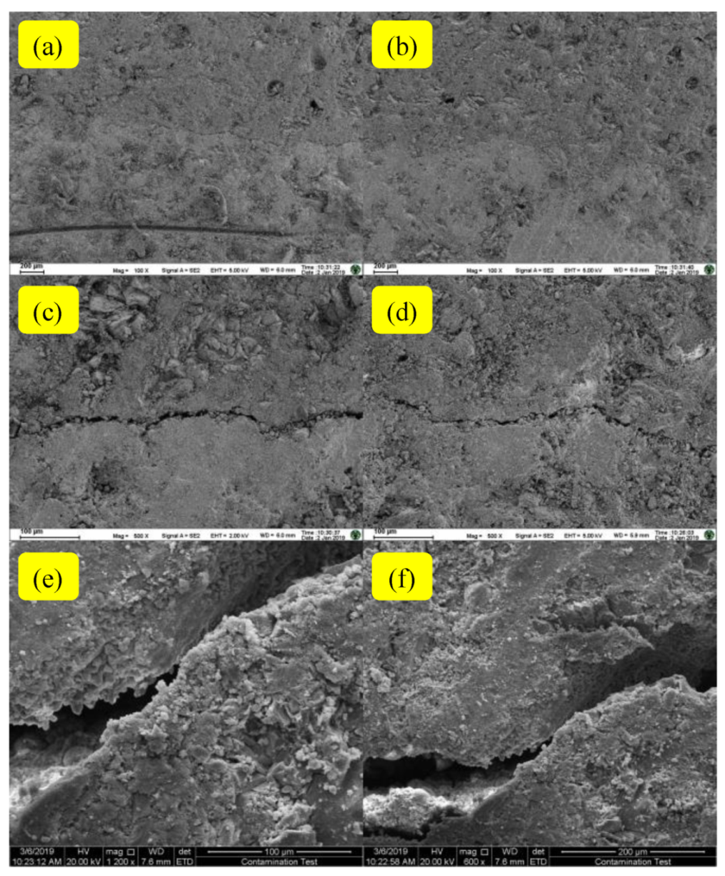
2.6. Microscopic Interface Observation

The macromechanical behavior of bonding interface is related to its microstructure. Scanning electron microscopy (SEM) was used in this study to observe the micromorphology of ECC-to-deck interface to evaluate the interface from a microscopic perspective and account for the macro phenomenon. The equipment used in this study was FEI Inspect F50. The specimens were exposed to freeze-thaw cycles and hygrothermal environment to study the changes in interfacial morphology in a hostile environment.

3. Results and Discussion

3.1. Mechanical Properties of ECC

Figure 7 shows the typical load-displacement curves of ECC under tension and bending. The curves of ECC under uniaxial tension or bending can be divided into three stages, namely, the elastic stage before cracking, the strain-hardening stage after cracking, and the final stress relaxation stage. Before the initial crack occurs in ECC, ECC is similar to an elastomer, and the load linearly varies with deformation. After the stress reaches the strength of matrix, microcracks occur in ECC, and then the strain-hardening stage begins. After the crack is formed, the tensile stress of this part will be borne by the fibers alone. The bridging stress of fibers plays a role in effectively transferring stress. In the stress relaxation stage, with the increase of deformation, the crack opening displacement gradually increases, and the overall strength of the material decreases accordingly.

3.2. Failure Mode of Steel-ECC Interface

Figure 8 shows the typical load-displacement curves of single shear test and pull-off test. The specimens were suddenly destroyed, accompanied by a loud cracking sound when they reached their ultimate loads. The failure was brittle and occurred with a relatively small deformation.
Figure 9 shows the specimens after failure. The failure occurred along the interface between the steel plate and ECC, and a thin layer of ECC was peeled off and adhered to the steel plate after destruction. Broken and pulled-out fibers were covered with damaged surfaces.

3.3. Effect of Freeze-Thaw on Interfacial Strength

Shear and pull-off tests were performed after completing 25, 50, 75, and 100 freeze-thaw cycles to evaluate the effect of freeze-thaw on the strength. Figure 10a,b show the results of single shear test; Figure 10c,d show the results of the pull-off test.
The results show that the interfacial shear strength decreases with an increase in freeze-thaw cycles. The shear strength decreased by 3.7%, 6.5%, 7.4%, and 9.9% after 25, 50, 75, and 100 freeze-thaw cycles, respectively. The pull-off strength showed a trend that was similar to shear strength. The pull-off strength decreased by 2.4%, 6.3%, 9.3%, and 13.9% after 25, 50, 75, and 100 freeze-thaw cycles, respectively. The shear strength and pull-off strength were approximately linear with the number of freeze-thaw cycles, as shown in Figure 10b,d.
Figure 11 shows the load-displacement curves of shear test under different freeze-thaw cycles to further analyze the effect of freeze-thaw on interfacial strength. The freeze-thaw cycles led to a dual degradation of stiffness and strength. In general, a lot of voids or microcracks are present in the interface between ECC and steel plate. During the freeze-thaw cycle, water that intruded into the interface was frozen, and ice expansion and melting led to the degradation of interface bonding performance. ECC itself was also damaged by freeze-thaw, as it experiences an increase in void ratio and a decrease in stiffness due to freeze-thaw [23,24,25]. A larger deformation occurred in ECC under the loading when the number of freeze-thaw cycles increased. Therefore, ECC and the interface between ECC and steel plate were both affected by freeze-thaw action, which led to the degradation of both strength and stiffness.

3.4. Effect of Hydrothermal Aging on Interfacial Strength

The specimens were placed in 60 °C water for 7, 14, 21, and 28 days to evaluate the effect of hot and humid condition on the interface. Figure 12 shows the results of single shear and pull-off tests.
The test results show that a hot and humid environment clearly affects the bonding performance of the steel plate and ECC, and both the shear strength and pull-off strength decrease to a certain extent after the immersion in hot water. The shear strength decreased by 1.36%, 6.64%, 10.02%, and 20.94% after 7, 14, 21, and 28 days’ immersion, respectively. The puff-off strength decreased by 2.67%, 7.63%, 13.85%, and 23.97% after 7, 14, 21, and 28 days’ immersion, respectively. An excellent fitting effect can be obtained using a quadratic polynomial to fit the relationship between strength and immersion time in hot water.
The effect of hot and humid environment on the bond strength between steel plate and ECC mainly includes the following: (1) influence on the properties of ECC materials, (2) influence on the epoxy adhesive, and (3) influence on the interface of ECC and epoxy adhesive. ECC and epoxy adhesive were softened during immersion in hot water. However, no appreciable microvoids were observed in the bond interface, and the interfacial failed in relatively weak areas under the action of water corrosion. The bonding strength of interface decreased with the duration of exposure to hot and humid environment. The longer the duration of exposure to the humid and hot environment, the more water entered through the microcracks of the bonding interface, thus deteriorating the performance of interface and hindering the force transmission. Besides, the inconsistency in dry shrinkage and wet expansion between different materials (such as ECC and epoxy adhesive) in the interface area and the inconsistency in the mechanical properties of different materials in the interface area also deteriorated the performance of bonding interface in the hydrothermal environment.

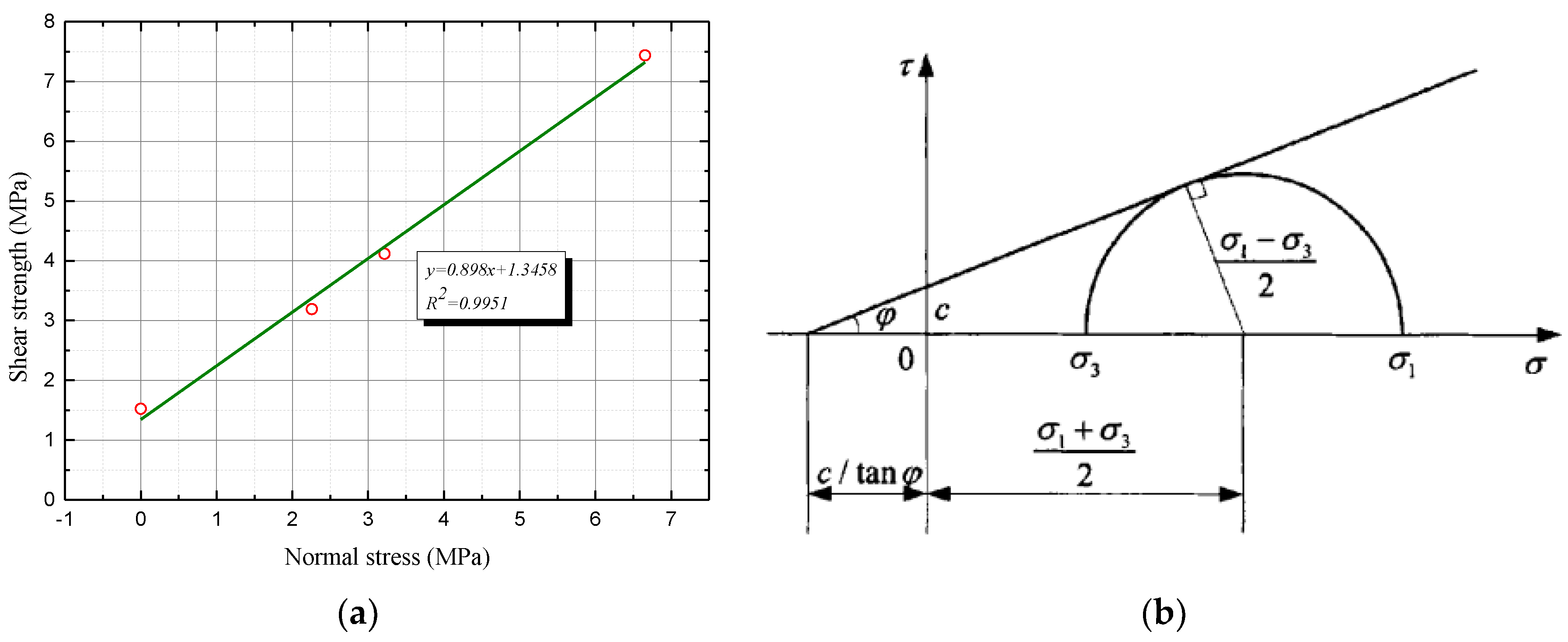
3.5. Criterion of Interfacial Failure Based on Inclined Shear Test

The shear strength that was obtained by the single shear test is the maximum shear stress without normal stress. When the normal stress was varied, the critical value of shear stress corresponding to failure was significantly affected. Fixtures with different inclination angles were used in this study to obtain the failure criterion for the interface. Notably, the single shear strength can be regarded as the result under the condition of 90° inclination angle. Table 5 and Figure 13 show the results of shear tests.
The experimental results show that the normal stress and shear strength have a linear relationship [26]. Therefore, the criterion of interface failure can be expressed, as follows:
τ m a x = τ C + k σ C
where τ C and k are the constants that characterize the interfacial strength properties. According to Figure 13a, the interfacial failure criterion for steel-ECC bonding interface can be expressed as follows:
τ m a x = 1 . 3458 + 0 . 898 σ C
Through the above analysis, the following conclusions can be drawn:
(1)
The initiation of interface failure occurs at the maximum interfacial shear stress.
(2)
The initiation of interface failure is influenced by normal stress at the interface. The greater the interfacial compressive stress, the greater the maximum interfacial shear stress.
(3)
The interface failure criterion is similar to Mohr–Coulomb criterion (shown in Figure 13b), i. e., the effect of interface compressive stress on the maximum interface shear stress is linear when failure occurs. The criterion is found to exclude the effect of experimental conditions and reflect the intrinsic strength characteristics of interface.

3.6. Micromechanism of Bonding Property Reduction

In the experiment, a thin layer of ECC was peeled with a steel plate, irrespective of whether shear or tensile stress caused the failure, as shown in Figure 14. The micromechanical behavior of bonding interface is related to the microstructure and properties of bonding interface. Two interfaces exist from the microscopic perspective: the interface between adhesive and ECC and the interface between adhesive and steel bridge deck. Some water from the ECC mix was retained between the ECC and epoxy, so it was difficult to guarantee the interface performance between adhesive and ECC. Based on the microbonding mechanism, the bonding force of ECC and adhesives is composed of chemical bonding force, van der Waals force, and mechanical biting force. In this study, the chemical bonding force is the adsorbing force that is produced by the cement gel on a colloid surface. It originated from the growth and hardening of cement crystal during the penetration and curing of cement paste into the colloid layer, which depended on the properties of cement and the roughness of colloid surface. However, the adhesion force was lost when the interface was deformed and slipped. Van der Waals force is an attractive force that exists between molecules. Chemical forces and van der Waals forces coexist on the surfaces, but their proportion in surface forces depends on the specific situation.
Vibration and hardening of cast-in-situ ECC along the interface, the colloid thickness between steel plate and ECC is not completely consistent, owing to the influence of pouring (shown in Figure 15). This affects the interface strength. The effect of interface morphology on shear is obvious, because the concave and convex surfaces at the interface caused the two sides of the interface to have a significant mechanical biting effect. When the interface was formed, the side of concave and convex part provided an excess bonding area as compared to the plane area. The increase in contact area was beneficial to the strength of interface along the vertical direction (i.e., pull-off strength), even though the effect was weak.
Microscopic interface bonding morphology was observed by using an SEM in this study. The results confirm that the presence of many small defects at the interface between ECC and adhesive. Those microholes or microcracks not only reduced the bearing area, but also became the channel through which water entered the interface and caused damage. Figure 16 shows that exposure to freeze-thaw cycles and the hot and humid environment increased the interfacial cracks. The presence of water further reduced the effective bearing area, worsened the interface bonding ability, and reduced the macroperformance.

4. Conclusions

This study used ECC as an overlay of an orthotropic steel bridge deck and evaluated the feasibility of using an epoxy adhesive to achieve wet-bonding between the steel deck and cast-in-place ECC. Single shear test and pull-off test were conducted in order to evaluate the bonding properties after the specimens were subjected to freeze-thaw cycles and hot and humid environment. Based on the results obtained in this study, the following conclusions can be drawn:
(1)
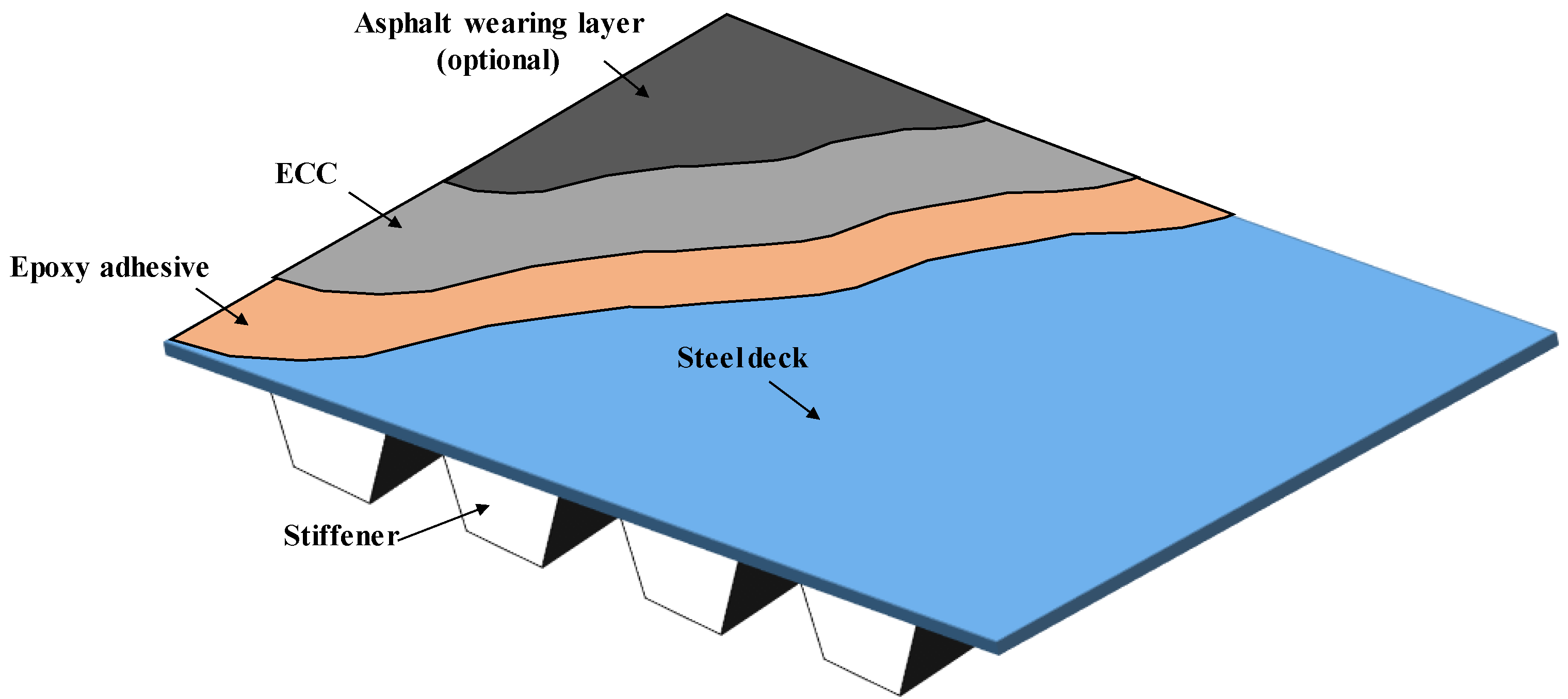
Wet-bonding technology using epoxy adhesive can provide a convenient alternative to the traditional mechanical shear key bonding method and introduce opportunities to develop new overlay structures for orthotropic steel deck bridges.
(2)
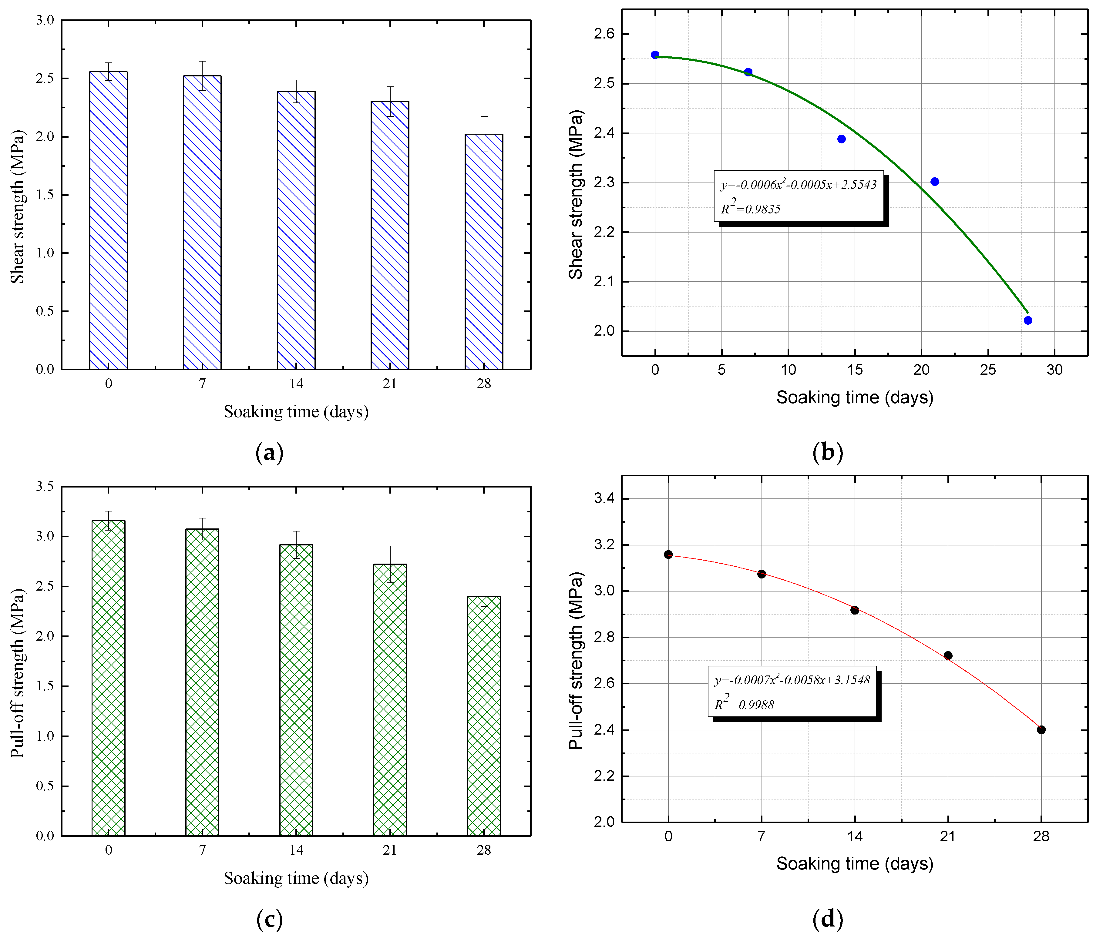
The interfacial shear and pull-off strength decrease with an increase in the freeze-thaw cycles and with the duration of immersion in hot and humid environment. The strength is approximately linear with the number of freeze-thaw cycles. Perfect fitting can be obtained while using a quadratic polynomial to fit the relationship between strength and duration of immersion in hot water.
(3)
The SEM images show the presence of microvoids or microcracks at the interface. Exposure to freeze-thaw cycles and hot and humid environment increased interfacial defects. The presence of water reduces the effective bearing area, worsens the interface bonding ability, and degrades the macroperformance.
(4)
The interfacial shear stress is linear with the normal stress. The failure criterion under normal stress for the steel-ECC bonding interface can be obtained as τ max = 1 . 3458 + 0 . 898 σ C , which is similar to Mohr–Coulomb criterion.

Author Contributions

Conceptualization, S.W. and J.Y.; methodology, R.Y.; formal analysis, J.Z.; data curation, X.S.; writing—original draft preparation, S.W.; supervision, J.Y. All authors have read and agreed to the published version of the manuscript.

Funding

This research was funded by National Natural Science Foundation of China (No. 51778140, 51578290). And it was also supported by the Fundamental Research Funds for the Central Universities and Postgraduate Research & Practice Innovation Program of Jiangsu Province (No. KYCX18_0137).

Conflicts of Interest

The authors declare no conflict of interest.

References

  1. Li, J.L.; Liu, X.Y.; Scarpas, T.; Tzimiris, G. Numerical simulation of orthotropic steel deck bridges with two membrane layers systems. J. Traffic Transp. Eng. 2013, 13, 1–8. [Google Scholar]
  2. Murakoshi, J.; Yanadori, N.; Ishii, H. Research on steel fiber reinforced concrete pavement on orthotropic steel deck. In Proceedings of the 2nd International Orthotropic Bridge Conference, Sacramento, CA, USA, 25–29 August 2008. [Google Scholar]
  3. Walter, R.; Olesen, J.F.; Stang, H.; Vejrum, T. Analysis of an orthotropic deck stiffened with a cement-based overlay. J. Bridge Eng. 2007, 12, 350–363. [Google Scholar] [CrossRef] [Green Version]
  4. Li, V.C. From Micromechanics to structural engineering-the design of cementitious composites for civil engineering application. J. Struct. Eng. Earthq. Eng. 1993, 10, 37–48. [Google Scholar]
  5. Kequan, Y.; Lingzhi, L.; Jiangtao, Y.; Jianzhuang, X.; Junhong, Y.; Yichao, W. Feasibility of using ultra-high ductility cementitious composites for concrete structures without steel rebar. Eng. Struct. 2018, 170, 11–20. [Google Scholar]
  6. Qian, S.; Kim, Y.Y.; Li, V.C. Influence of concrete material ductility on shear response of stud connections. ACI Mater. J. 2011, 103. [Google Scholar]
  7. Shao, Y.; Wu, Z.; Bian, J. Wet-bonding between FRP laminates and cast-in-place concrete. In Proceedings of the International Symposium on Bond Behaviour of FRP in Structures, Hong Kong, China, 7–9 December 2005; pp. 91–96. [Google Scholar]
  8. Wu, Z.S.; Yin, J. Fracture behaviours of FRP-strengthened concrete structures. Eng. Fract. Mech. 2003, 70, 1339–1355. [Google Scholar] [CrossRef]
  9. Wu, Z.; Li, W.; Sakuma, N. Innovative externally bonded FRP/concrete hybrid flexural members. Compos. Struct. 2006, 72, 289–300. [Google Scholar] [CrossRef]
  10. Deskovic, N.; Triantafillou, T.C.; Meier, U. Innovative design of FRP combined with concrete: Short-term behavior. J. Struct. Eng. 1995, 121, 1069–1078. [Google Scholar] [CrossRef]
  11. Canning, L.; Hollaway, L.; Thorne, A.M. An investigation of the composite action of an FRP/concrete prismatic beam. Constr. Build. Mater. 1999, 13, 417–426. [Google Scholar] [CrossRef]
  12. Hulatt, J.; Hollaway, L.; Thorne, A. Short term testing of hybrid t beam made of new prepreg material. J. Compos. Constr. 2003, 7, 135–144. [Google Scholar] [CrossRef]
  13. Shao, X.; Yi, D.; Huang, Z.; Zhao, H.; Chen, B.; Liu, M. Basic performance of the composite deck system composed of orthotropic steel deck and ultrathin RPC layer. J. Bridge Eng. 2013, 18, 417–428. [Google Scholar] [CrossRef]
  14. Bizindavyi, L. Transfer lengths and bond strengths for composites bonded to concrete. J. Compos. Constr. 1999, 3, 153–160. [Google Scholar] [CrossRef]
  15. Nakaba, K.; Kanakubo, T.; Furuta, T.; Yoshizawa, H. Bond behavior between fiber-reinforced polymer laminates and concrete. ACI Struct. J. 2001, 98, 359–367. [Google Scholar]
  16. Li, L.; Shao, Y.X.; Wu, Z.S. Durability of wet bond of hybrid laminates to cast-in-place concrete. J. Compos. Constr. 2010, 14, 209–216. [Google Scholar] [CrossRef]
  17. Ren, H.; Yao, Q.; Hu, A. Experimental study on durability of fiber reinforced composites. J. Build. Mater. 2005, 8, 520–526. [Google Scholar]
  18. GB/T 714-2015. Structural steel for bridge. In General Administration of Quality Supervision, Inspection and Quarantine of the People’s Republic of China (AQSIQ) and Standardization Administration of the People’s Republic of China (SAC); AQSIQ: Beijing, China, 2015. [Google Scholar]
  19. Liu, S.; Yang, J.; Chen, X.; Yang, G. Application of mastic asphalt waterproofing layer in high-speed railway track in cold regions. Appl. Sci. 2018, 8, 667. [Google Scholar] [CrossRef] [Green Version]
  20. Subramaniam, K.V.; Ali-Ahmad, M.; Ghosn, M. Freeze-thaw degradation of FRP-concrete interface: Impact on cohesive fracture response. Eng. Fract. Mech. 2008, 75, 3924–3940. [Google Scholar] [CrossRef]
  21. Biscaia, H.C.; Chastre, C.; Borba, I.S.; Silva, C.; Cruz, D. Experimental evaluation of bonding between CFRP laminates and different structural materials. J. Compos. Constr. 2015, 20, 04015070. [Google Scholar] [CrossRef]
  22. GB/T 50082-2009. Standard for test methods of long-term performance and durability of ordinary concrete. In General Administration of Quality Supervision, Inspection and Quarantine of the People’s Republic of China (AQSIQ) and Ministry of Housing and Urban-Rural Development of the People’s Republic of China (MOHURD); AQSIQ: Beijing, China, 2009. [Google Scholar]
  23. Lu, C.; Li, V.C.; Leung, C.K.Y. Flaw characterization and correlation with cracking strength in engineered cementitious composites (ECC). Cem. Concr. Res. 2018, 107, 64–74. [Google Scholar] [CrossRef]
  24. Chen, J.; Yao, C.; Wang, H.; Huang, W.; Ma, X.; Qian, J. Interface Shear Performance between Porous Polyurethane Mixture and Asphalt Sublayer. Appl. Sci. 2018, 8, 623. [Google Scholar] [CrossRef] [Green Version]
  25. Tian, J.; Wang, W.; Du, Y. Damage behaviors of self-compacting concrete and prediction model under coupling effect of salt freeze-thaw and flexural load. Constr. Build. Mater. 2016, 119, 241–250. [Google Scholar] [CrossRef]
  26. Yao, B.; Zhang, Y.; Li, F. Shear characteristics of interface between steel bridge deck and epoxy asphalt pavement. China J. Highw. Transp. 2017, 30, 132–138. [Google Scholar]
Figure 1. Overlay structure for orthotropic steel deck bridges.
Applsci 10 02123 g001
Figure 2. Preparation of wet-bonding specimens.
Applsci 10 02123 g002
Figure 3. Mechanical performance tests: (a) Tensile test, (b) Bending test.
Applsci 10 02123 g003
Figure 4. Single shear test: (a) Front view, (b) Side view.
Applsci 10 02123 g004
Figure 5. Pull-off test: (a) Specimen, (b) Instrument.
Applsci 10 02123 g005
Figure 6. Inclined shear test.
Applsci 10 02123 g006
Figure 7. Typical load-displacement curves of engineered cementitious composite (ECC) under tension and bending: (a) Tension, (b) Bending.
Applsci 10 02123 g007
Figure 8. Typical load-displacement curves: (a) single shear test and (b) pull-off test.
Applsci 10 02123 g008
Figure 9. Interfacial failure: (a) single shear test and (b) pull-off test.
Applsci 10 02123 g009
Figure 10. Effect of freeze-thaw cycles on strength: (a) Changes in shear strength, (b) fitting of shear strength and freeze-thaw cycles, (c) changes in pull-off strength, and (d) fitting of pull-off strength and freeze-thaw cycles.
Applsci 10 02123 g010
Figure 11. Typical curves of shear test under different freeze-thaw cycles.
Applsci 10 02123 g011
Figure 12. Effect of hot and humid environment on strength: (a) Changes in shear strength, (b) fitting of shear strength and soaking time, (c) changes of pull-off strength, and (d) fitting of pull-off strength and soaking time.
Applsci 10 02123 g012
Figure 13. Shear test results: (a) Interfacial failure criterion, (b) Mohr–Coulomb criterion.
Applsci 10 02123 g013
Figure 14. Schematic diagram of interfacial failure.
Applsci 10 02123 g014
Figure 15. Nonuniform distribution of colloid thickness.
Applsci 10 02123 g015
Figure 16. Scanning electron microscopy (SEM) images: (a,b) Original interface, (c,d) 100 freeze-thaw cycles, (e,f) 28 days’ immersion in hot water.
Applsci 10 02123 g016
Table 1. Chemical composition of Portland cement and fly ash.
MaterialChemical Components (by Weight, %)
SiO2CaOAl2O3Fe2O3SO3P2O5K2ONa2OTiO2MgO
Cement21.2657.827.672.884.045.260.78-0.21-
Fly ash56.182.8231.463.850.690.91-1.32-1.33
Table 2. Physical and mechanical properties of polyvinyl alcohol (PVA) fiber.
Diameter (μm)Length (mm)Elongation (%)Density (g/cm3)Elastic Modulus (GPa)Tensile Strength (MPa)
35127.31.331.31287
Table 3. Mix design (kg/m3).
CementFly AshWaterSandFiberWater Reducer
479 719 359 431269.6
Table 4. Properties of epoxy binder.
Strength (MPa)Modulus(GPa)Elongation Rate
TensionCompressionShearTensionCompressionShear
25758.94.65.03.050.30%
Table 5. Results of shear tests.
Inclination Angle (°)Shear Strength (MPa)Normal Stress (MPa)
Measured ValueMean ValueStandard DeviationMeasured ValueMean ValueStandard Deviation
26.577.6537.4390.2356.8456.6540.211
7.1876.428
7.4776.687
38.663.9254.1190.2233.0653.2170.174
4.3633.407
4.0693.177
45.002.9883.1930.2062.1132.2580.146
3.1922.257
3.3992.404
90.001.5641.5250.0340.0000.0000.000
1.5030.000
1.5070.000

