Article

Rail Pad Corrosion Effects on the Dynamic Behavior of Direct Fixation Track Systems in Marine Environments

1
Department of Construction Engineering, Dongyang University, No. 145 Dongyangdae-ro, Pugggi-eup, Yeongju-si, Gyeongsangbuk-do 36040, Korea
2
Technical Planning & Electric Department, Airport Railroad Co., Ltd, No. 46, Geombawi-ro, Seo-gu, Inchoen 22694, Korea
3
Department of Architectural Engineering, Gachon University, 1342 Seongnamdaero, Sujeong-gu, Seongnam-si, Gyeonggi-do 13120, Korea
*
Author to whom correspondence should be addressed.
Appl. Sci. 2020, 10(7), 2245; https://doi.org/10.3390/app10072245
Submission received: 5 March 2020 / Revised: 23 March 2020 / Accepted: 25 March 2020 / Published: 26 March 2020
(This article belongs to the Special Issue Advances on Structural Engineering)

Abstract

:
This study experimentally investigated the effects of rail pad corrosion on the performance of the direct fixation track on a long-span railway bridge in marine conditions. In this study, the dynamic behavior of a direct fixation track on a railway bridge in the presence of corroded rail pads, was determined. Field measurements in this study show that the replacement of corroded rail pads does not affect the track support stiffness. The hard rail pads used in direct fixation tracks are intended to provide electrical insulation rather than flexural track behavior, and so their influence on track support stiffness was found to be insignificant given their high spring stiffness. Additionally, samples of new and corroded rail pads were collected and the spring stiffness of rail pads were analyzed using static, dynamic, and aging tests. The spring stiffnesses of new and corroded rail pads were found to be similar. This means that spring stiffness is not significantly affected by corrosion, a finding that could be explained by the fact that the deformation due to passing train loads was extremely small. Therefore, even though the rail pads on the study bridge exhibited some surface corrosion, their function was not impaired, and they did not need replacement.

1. Introduction

One of the main components in concrete track systems is the rail pad, which is installed between the rail and the sleeper to attenuate wheel/rail interaction loads This prevents the underlying railway sleepers from experiencing excessive stress [1]. Soft pads are typically used for concrete tracks. However, the direct fixation track on the Yeongjong Grand Bridge uses hard pads. The direct-fixation track is the earliest form of track without ballast. This direct fixation track exhibits integrated behavior because the rail and track girder are rigidly connected together by the direct fixation rail fastening system. Moreover, the direct fixation track system of the Yeongjong Grand Bridge is attached to a long-span special bridge (cable and truss); this concept originated from the track style of the Great Seto Bridge in Japan [2,3]. It is the only such track type in South Korea, and currently condition assessments and maintenance of this track are challenging [2,3]. Other general types of direct fixation tracks have been widely deployed in recent years, and maintenance instructions will be required in the future. An important issue in the maintenance of both concrete slab tracks and direct fixation tracks is the timely replacement of the rail pads, commonly known as elastic pads (i.e., resilience pads and rail pads) [4].
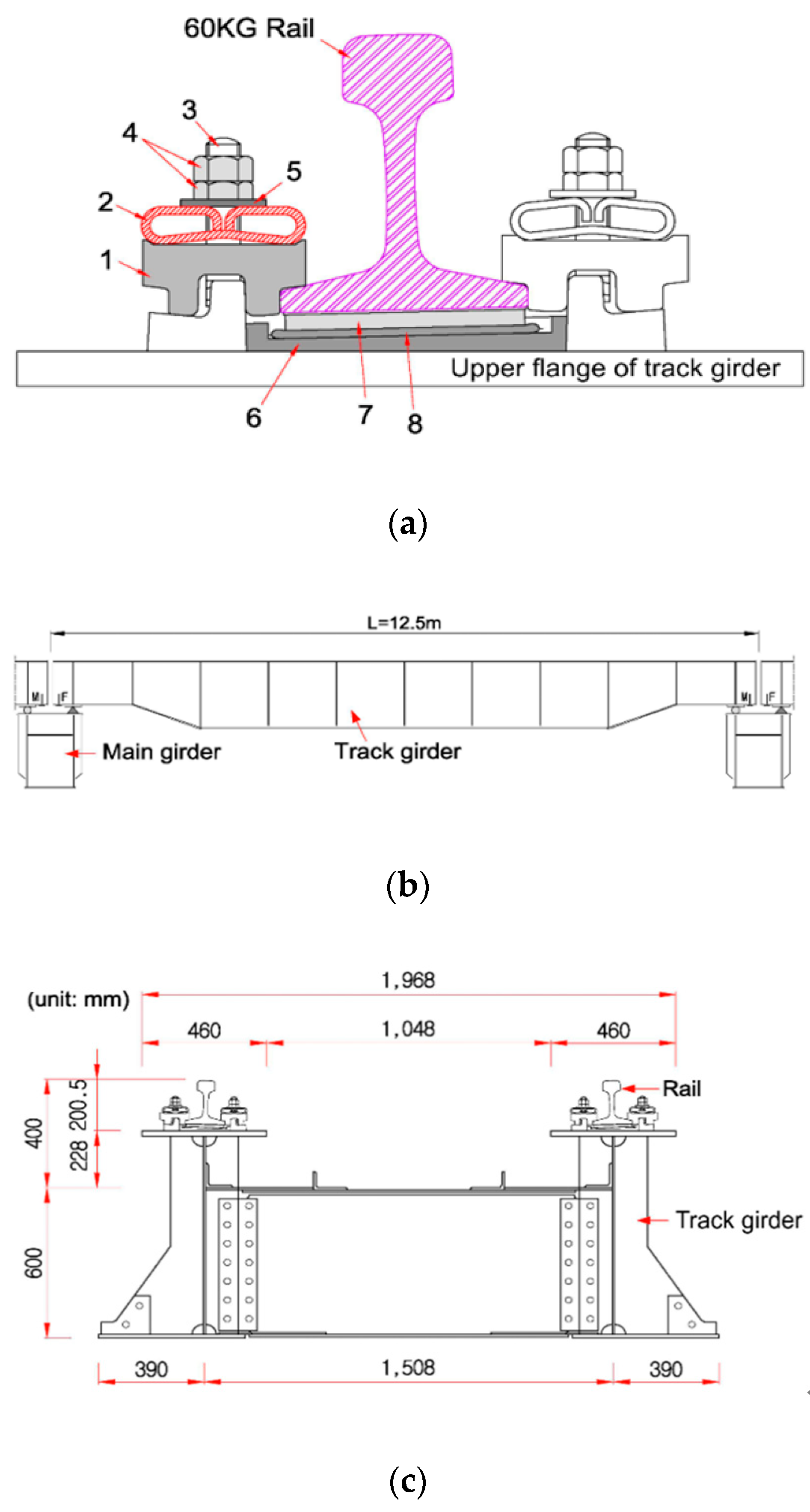
As shown in Figure 1a, the track system on the Yeongjong Grand Bridge is installed with a direct fixation rail fastening system on upper flange of the track girder. Moreover, as shown in Figure 1b, it is continuously arranged with simple supported beam-type track girders with a length of 12.5 m for supporting the rail. The rail weighs 60 kg with rail supporting point spacing of 0.625 m and the direct fixation track has a design speed of 110 km/h. The rail fastener of the direct fixation track is applied with a flat spring joint, a rail pad (SBR, styrene butadiene rubber), an adjustable pad, and the anti-loosening nut as shown in Figure 1a [2,3].
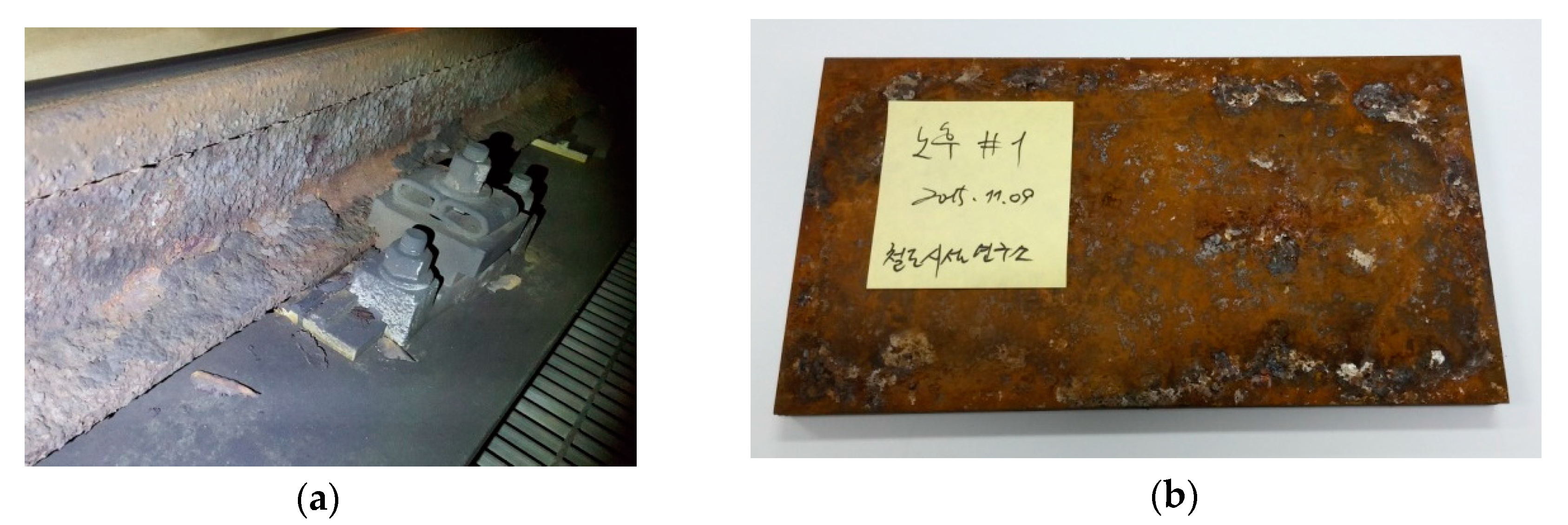
In the previous research, it was estimated that the annual direct cost of corrosion in highway bridges in 2002 was $8.3 billion, with indirect costs to users due to traffic delays and lost productivity, estimated to be 10 times. A significant portion of that cost can be tied directly to replacement costs for bridge decks, which are damaged principally due to corrosion of reinforced steel caused by deicing chemicals, primarily sodium chloride and calcium chloride [5,6]. Deterioration of bridge decks is a primary factor limiting the lifespan of bridges especially in cold climates where deicing salts are commonly used. While controlling deck cracking or decreasing the permeability and porosity of concrete can improve the performance and service life of bridges, chloride, and moisture ingress as well as cracking cannot be completely eliminated. Full-depth cracks, which are caused by restrained shrinkage, lead to corrosive conditions at early ages for both the top and bottom reinforcement mats [7]. According to a study by Cope et al., the use of stainless steel elements as bridge deck reinforcements in a critical situation significantly increased the initial cost but significantly reduced the overall life-cycle cost, making it cost effective in the long term [8]. In this study, the rail pad has a laminated structure. The upper surface is made of stainless steel and the lower surface is made of SBR material. SBR has a good abrasion resistance and good aging stability when protected by additives [9]. The stainless steel on the top surface is in contact with the bottom of the rail and the SBR at the bottom is in contact with the adjustable pad. The stainless steel element was attached to the rail pads in order to mitigate the longitudinal interaction of the long-span railway bridge and direct the fixation track so that the longitudinal expansion of the continuous welded rail is relatively free. The original track of this bridge was designed as a rail-fastening system capable of acting in the longitudinal direction owing to concerns about the longitudinal bridge–track interaction force and expansion behavior, which could be observed using a rail pad with stainless steel. However, even though such rail pads were corroded, by installing a number of rail expansion joints in the bridge section to accommodate the expansion and contraction behavior in the rail, no structural problems occurred in the longitudinal direction. The stainless steel member attached to the rail pads was corroded in marine condition as shown in Figure 2, and its appearance is concerned about whether the rail pads function properly.
In general, the track support stiffness of a direct fixation applied to concrete tracks can be calculated based on the deflection of the rail [2]. The track support stiffness of a specified track structure using soft elastic pads can be directly affected by variations in the spring stiffness of the elastic pads. Variations in the spring stiffness of the elastic pads can also cause changes in the vehicle–track interaction force and the dynamic behavior of the entire track system [4]. Therefore, in the case of typical concrete tracks, periodic and timely replacement of the rail pads is important for track maintenance [2,4,10]. Lee [11] experimentally assessed the effect of fatigue on the resilience pads of sleeper floating tracks in South Korea based on the prediction and assessment of changes in their spring stiffness. Park [12] conducted simple fatigue tests on the elastic pads of a rail fastening system for concrete slab tracks, but a durability assessment based on simple fatigue could not properly reflect the actual field conditions. Lim et al. [13] predicted the fatigue life of continuous welded rails using various parameters to calculate the rail replacement periods. They found that the rail bending fatigue life was reduced by approximately 32% when the pad stiffness decreased from 50 to 10 kN/mm, and that the rail bending fatigue life gradually converged to its maximum once the pad stiffness exceeded 200 kN/mm. It was found that rail pads with spring stiffness of greater than 200 kN/mm did not show any significant increase in spring stiffness with increasing service life. Therefore, the management of softer rail pads was important in terms of increasing the service life of the rail. Moreover, Lei and Zhang [14] investigated the parameters of a concrete slab track that determine track vibration, such as the spring stiffness and damping properties from the rail pads, the cement–asphalt (CA) mortar, and the subgrade, in order to propose measures to reduce track vibration. The stiffness of the rail pads and the subgrade were found to be the factors governing track displacement, whereas the damping responses of the rail pads, CA mortar, and subgrade were not particularly influential. For track vibration, the influences of the spring stiffness and damping properties of rail pads were observed to be significant, whereas the effects attributed to the spring stiffness and the damping resulting from the CA mortar and the subgrade were able to be neglected [14]. Additionally, Korama et al. [15] investigated the effects of the preload and nonlinearity of rail pads on the vibration of a railway track under stationary and moving harmonic loads using the finite element method. They found that an increase in preload increased the dynamic spring stiffness of rail pads, and thus decreased the track displacement. Another study showed that direct fixation tracks on railway bridges can induce the integral behavior of the rail and the track girder (i.e., the rail support structure as a substructure) by using a harder rail pad, and that the elastic displacement of the rail of the direct fixation track is determined by the bending behavior of the track girder, which acts as a simple beam [2]. Currently, there is no clear standard for the maintenance of rail pads used in direct fixation tracks, and no studies have been conducted on their behavioral characteristics. Moreover, no prior study has investigated either a) the deterioration characteristics of rail pads, or b) the necessity of their periodic replacement. Therefore, in this study, the influence of rail pads on the dynamic behaviors of the direct fixation track on a railway bridge was estimated using field measurements and laboratory tests. The results were used to determine the necessity of rail pad replacement and can be used to inform maintenance strategies for direct fixation tracks.

2. Field Measurements

2.1. Overview

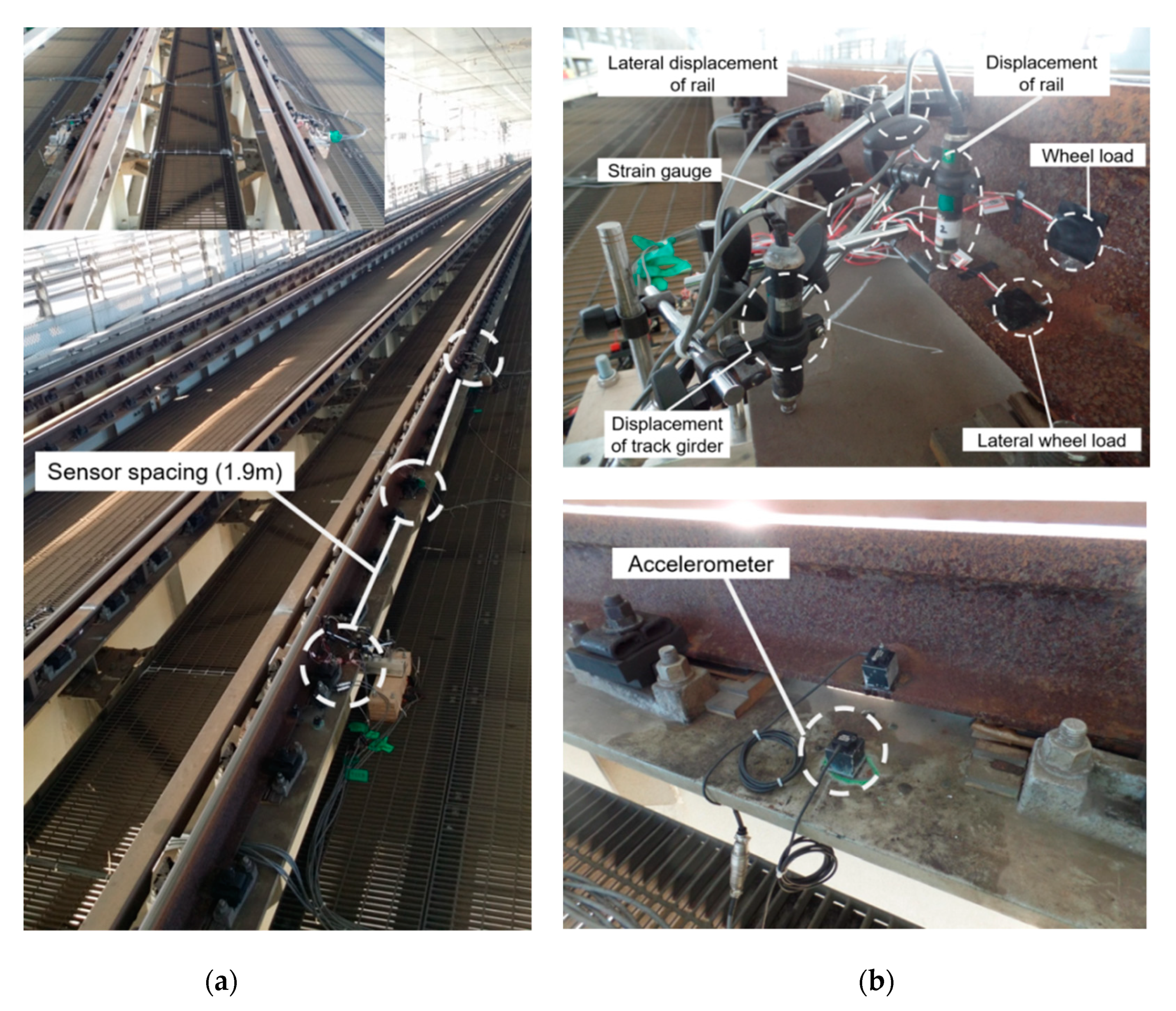
In this study, field measurements were performed to quantify the dynamic responses of direct fixation tracks to different train types (Airport Railroad Express (AREX) and Korea Train Express (KTX)) according to rail pad replacement. To experimentally evaluate the dynamic behaviors of the existing direct fixation track of the Yeongjong Grand Bridge, field measurements of the operational track were conducted. The location of the measurement was selected as the direct fixation track inside the truss bridge, as shown in Figure 3a,b. The vehicles operating in the measurement section were AREX (normal train) and KTX (high-speed train), which have different operational velocities and wheel loads. In this study, the dynamic responses of the track, which are generated while trains are running, were used for analysis. The properties of the trains running in the measurement section are presented in Table 1.
The dynamic wheel load and lateral wheel load for each position of the track girder including the support, the quarter, and center of the span, as well as the bending stress of the rail, the vertical acceleration of the rail and track girder, the vertical and lateral displacement of the rail, and the vertical displacement of track girder were measured, as shown in Figure 3a. Figure 3b shows the sensors installed at the site. The vertical wheel loads and lateral wheel loads were measured using a wheel–rail contact force sensor (i.e., shear strain gages coupled to a full Wheatstone bridge circuit [2,4,14]). The strain gage bridges were calibrated using a hydraulic ram and a load cell to obtain measurements with an accuracy of 2% [2,4,14]. The shear strain gages were attached to both rails between two consecutive rail supporting points [2,4]. The bending strain of the rail was measured by longitudinally attaching a one-axis strain gage to the bottom flange of the rail, as shown in Figure 3 [2]. The strain gage was placed between rail supporting points (i.e., a place of rail fastening system) at the center [2].
To prevent data distortion and loss, the sampling rate was set to 1 kHz [2,4,14]. The vertical rail and track girder displacements were measured using displacement transducers mounted on a jig anchored at the side bridge inspection passage, which was not affected by the passing train, as shown in Figure 3 [2]. To analyze the effects of vibrations generated by passing trains on the direct fixation rail and supporting girder, the track vibrations were analyzed before and after the replacement of the rail pads using accelerometers installed on the rail and girder as shown in Figure 3b. The accelerometers were installed in the vertical direction on the top surface of the rail flange and on the upper flange of the track girder at the between-rail supporting points (i.e., rail fastening system locations).

2.2. Measurement Results

As shown in Figure 4, the results of the dynamic wheel load measurements indicate no clear changes in the wheel loads with train speed because there was no significant difference in the traveling speeds of the trains passing over the measurement section. In addition, the measured wheel load ranges were found to be similar before and after rail pad replacement. As such, the measurement results indicate that rail pad replacement has an insignificant effect on the dynamic wheel load experienced by the track for all evaluated train types.
According to the measured dynamic wheel load results for rail pad replacement, the dynamic wheel load before rail pad replacement is similar to that after rail pad replacement, as shown in Figure 5a,b. The rates of all wheel load fluctuations calculated using the dynamic wheel load measurements were greater than zero, as shown in Figure 5c.
The results of the dynamic lateral wheel load measurements show that there were only minor changes under different speeds because the different train types traveled through the measurement section at similar speeds, as shown in Figure 6. In addition, the distribution of the measured lateral wheel load was found to be similar before and after rail pad replacement, as shown in Figure 6a,b. This indicates that rail pad replacement has little effect on the dynamic lateral wheel load for each train type.
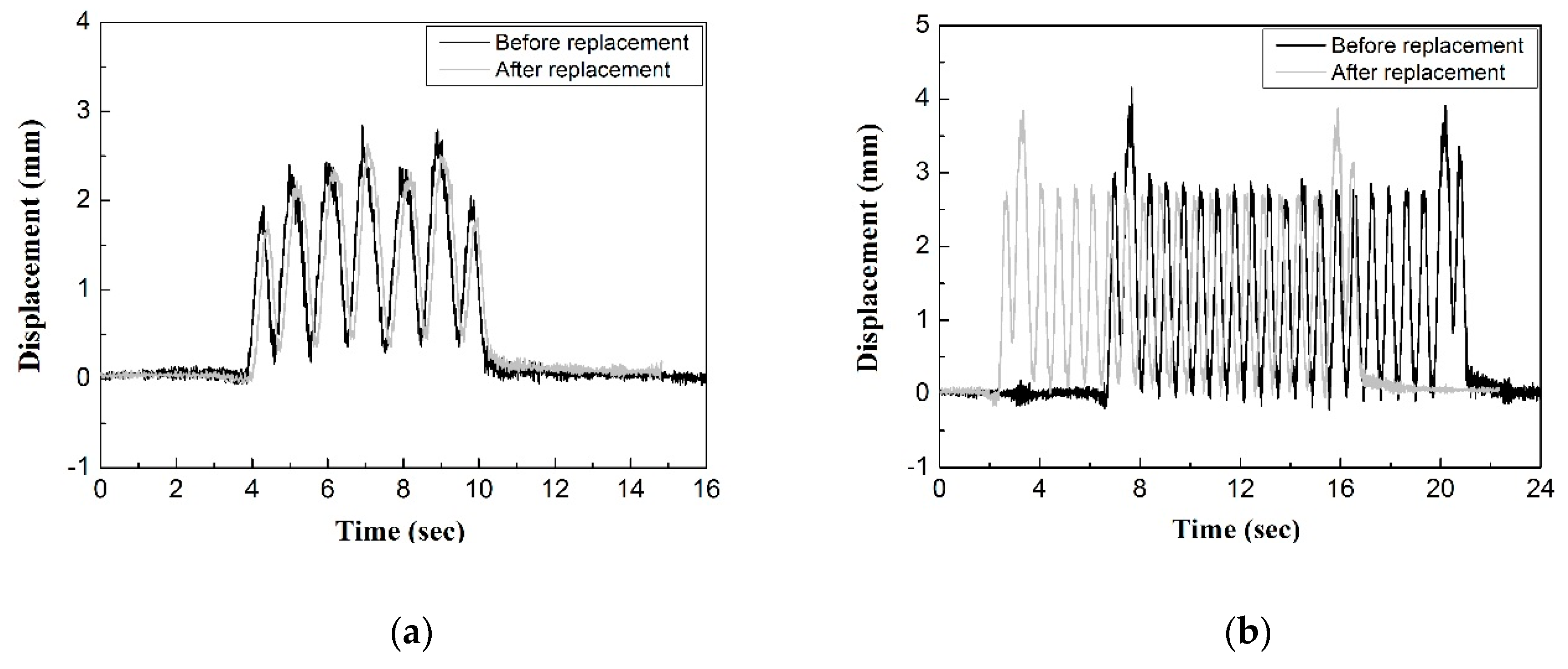
The measured displacement of the rail and the track girder according to rail pad replacement, as shown in Figure 7, was not significant.
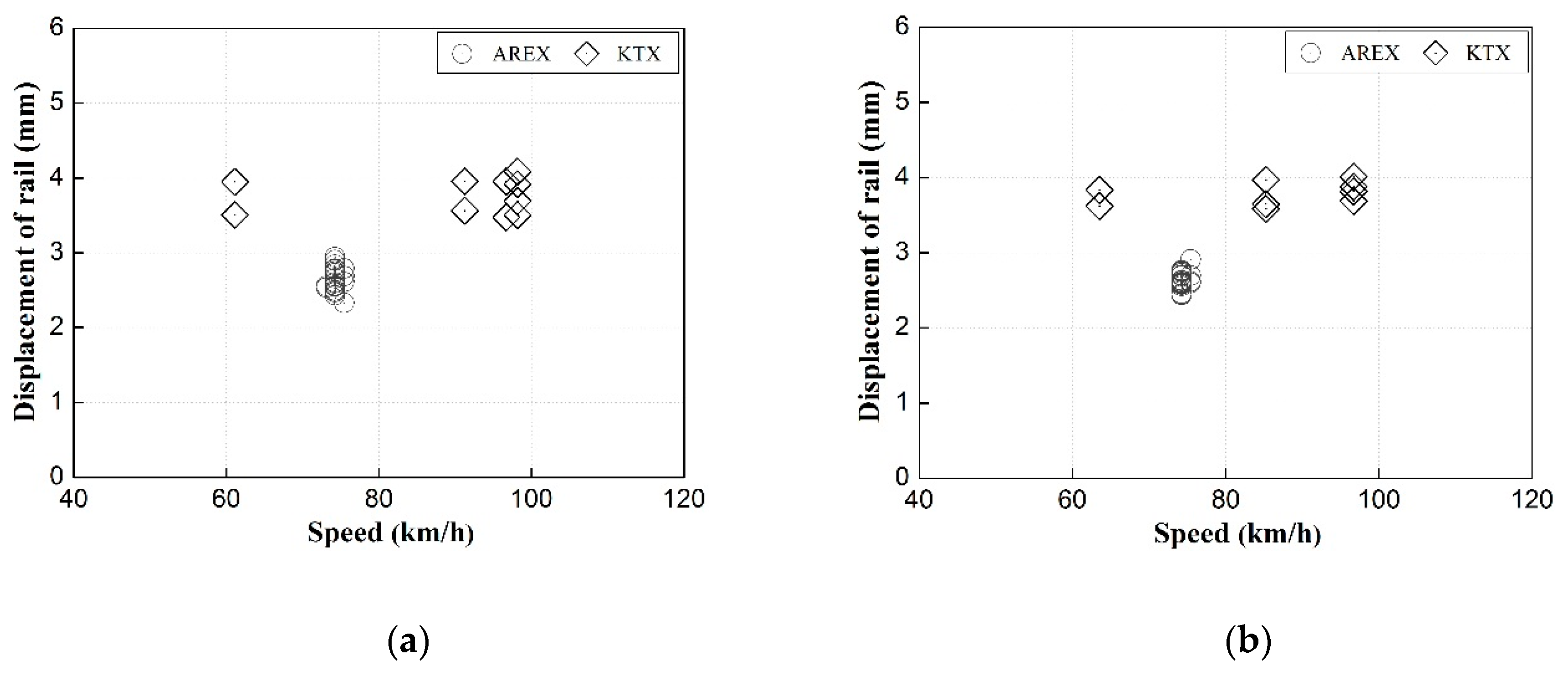
As shown in Figure 7, the difference in vertical displacement according to rail pad replacement between the rail and the track girder was approximately 3%–6%, indicating that the rail pad was insignificantly affected by changes in track displacement. This is due to the structural characteristic of the tested track, the relatively hard rail pad (kpad = 120–140 kN/mm), and the rail fastener with a strong fastening force [2]. Therefore, the rail and track girder were coupled with a strong force and exhibited integrated behavior, as there are no other components that provide elasticity between the rail and track girder [2]. The measured vertical rail displacements shown in Figure 8 indicate that there were insignificant changes in the vertical rail displacement under different traveling speeds for all tested train types in the measurement section. In addition, the distribution of vertical rail displacement was found to be similar before and after rail pad replacement, as shown in Figure 8a,b.
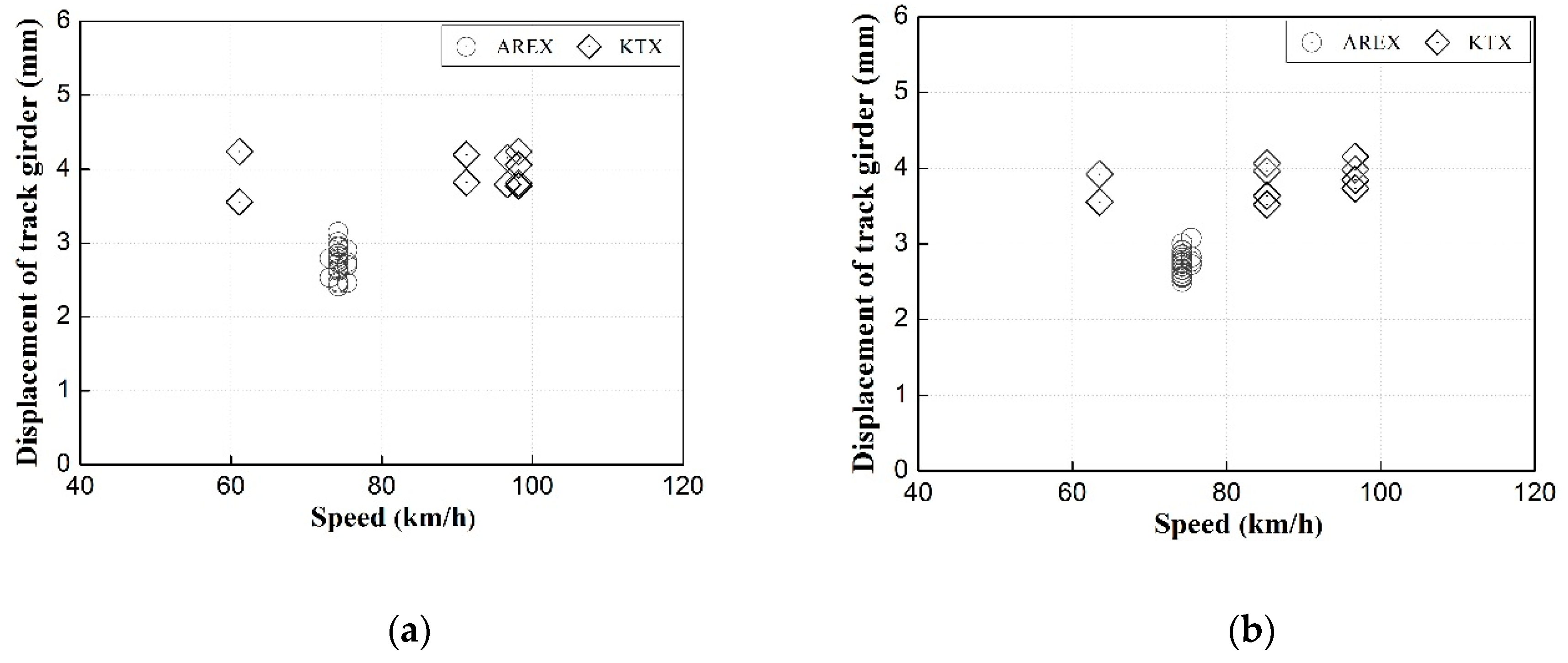
The measured displacement of the track girder shown in Figure 9 indicate that there were no significant changes in the displacement of the track girder under different traveling speeds for all tested train types in the measurement section. In addition, the distribution of track girder displacements was found to be similar before and after rail pad replacement, as shown in Figure 9a,b. This indicates that for each train type, the impact of rail pad replacement on track girder displacement was insignificant.
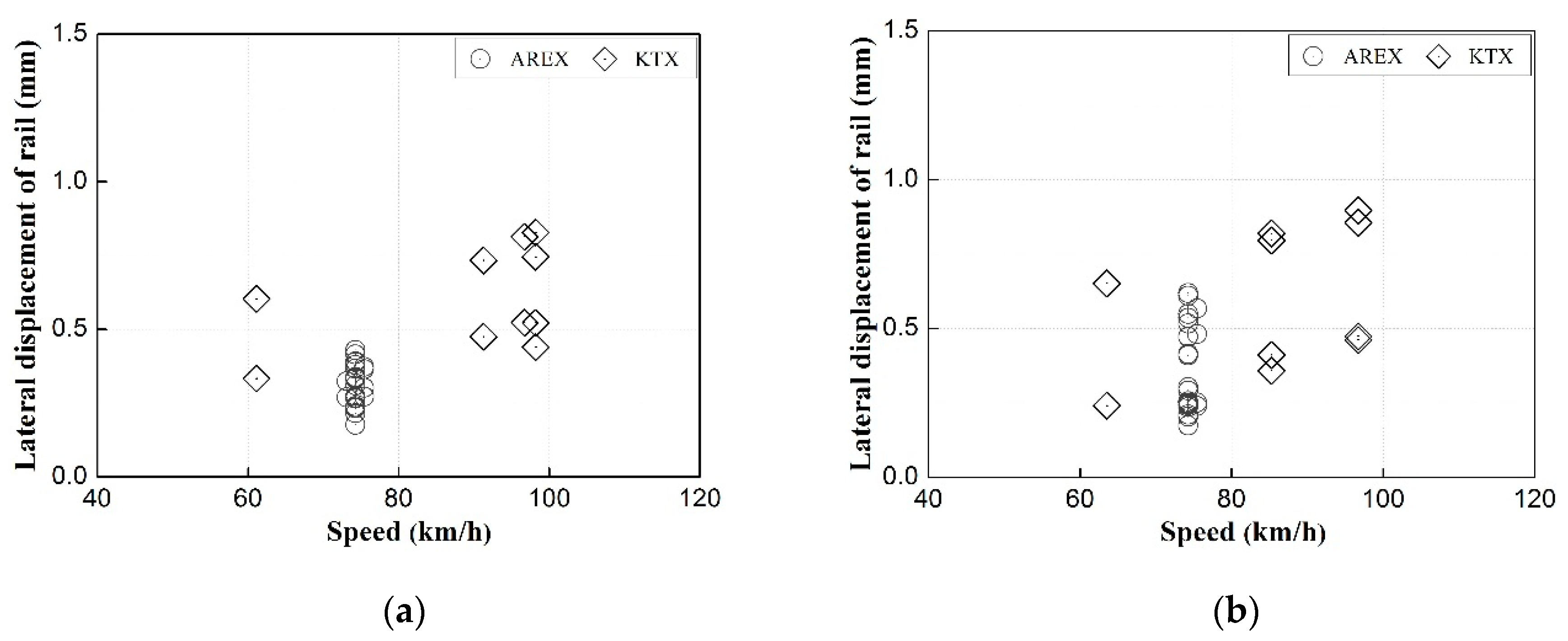
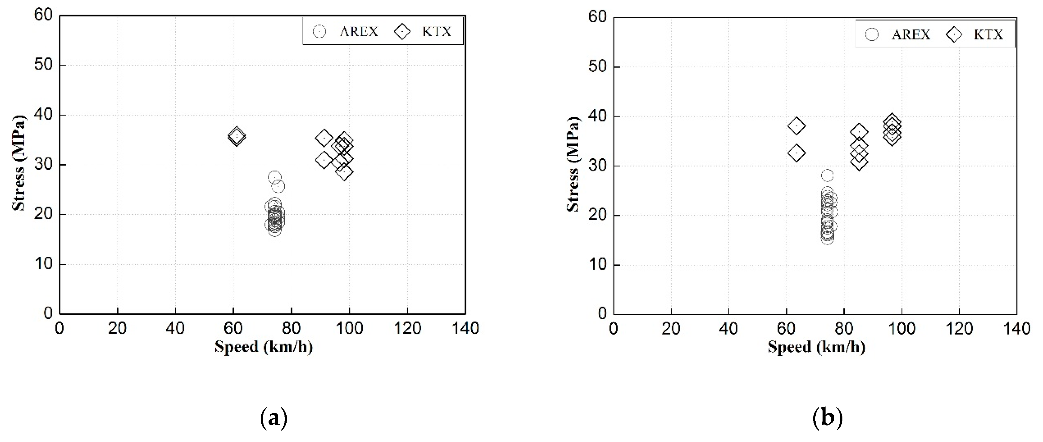
The measured lateral rail displacements and bending stress of the rail shown in Figure 10 and Figure 11 indicate that there were insignificant changes in the dynamic response under different traveling speeds for all tested train types. In addition, the distribution of lateral rail displacement and rail bending stress were found to be similar before and after rail pad replacement, as shown in Figure 10 and Figure 11.
The vertical displacements of the rail were found to be relatively large, as shown in Table 2. It was likely caused by the displacement of the track girder, as the rail bending stress was found to be lower than the rail bending stress (approximately 60 MPa) of the other types of railway track system (i.e., ballasted track, slab track, rail floating system, and sleeper floating system [2]).
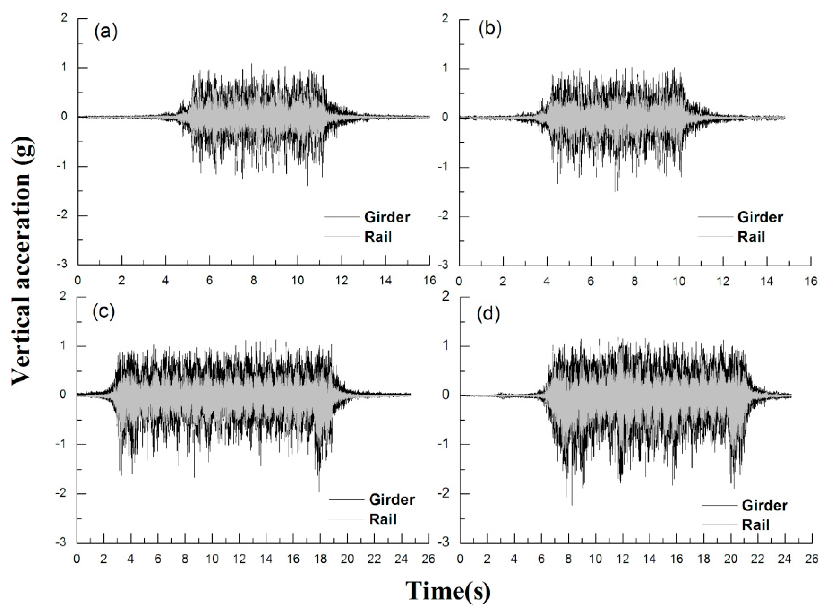
This study accordingly compared the dynamic responses of the rail and track girder to estimate the effects of rail pad replacement using measured acceleration data from the direct fixation track, as shown in Figure 12.
The vertical acceleration of the rail and track girder is shown in Figure 11 for different train types and at each speed. According to rail pad replacement, the variation was low (i.e., approximately 4%). The reason for this is that the rail pad in the direct fixation track system was supported by a relatively hard material; therefore, the rail and track girder of the direct fixation track system on the Yeongjong Grand Bridge exhibits integrated behavior [2,4].
This indicates that the influence of the spring stiffness of the rail pad on the dynamic response of the direct fixation track system of the Yeongjong Grand Bridge was insignificant.

2.3. Track Support Stiffness

Track support stiffness (TSS) is used as a quality index of railway tracks to assess their performance and bearing capacity [4,10]. The track support stiffness is measured in terms of the amount of deformation in tracks subjected to a passing train load [4,10]. The track support stiffness directly depends on the elastic stiffness of the elastic track components and the structural characteristics of the track system [4,10]. Therefore, the track support stiffness directly depends on the variations in the dynamic wheel load and deflections in the tracks [4,10,16,17]. Furthermore, the TSS values vary with the track structure (e.g., ballasted and slab tracks) and the structural characteristics of the slab track (elastic fastening system, rail floating system, sleeper floating system, and direct fixation track system) [4,10,16,17].
Track support stiffness is an indicator of track performance that provides a quality assessment indicating the bearing capacities of the track structure [2,4].
The analytical model of a general track structure is a linear spring model wherein each track component is connected to spring elements having different spring stiffnesses [4,10]. The stiffness of the track components such as rails and sleepers was excluded from the calculations of the elastic stiffness of the track structure; only the configuration of elastic-resilience materials was considered [4,10].
Several researchers have assumed that k can be expressed as a series of linear spring elements with different spring stiffnesses placed at the rail supporting point composed of a rail pad, sleeper, and roadbed (subsoil) connected in series following Equation (1) [4,10]. As shown in Equation (1), larger spring stiffness, such as that in the direct fixation track system of the Yeongjong Grand Bridge, is insignificantly affected by changes in track support stiffness.
k = 1 1 k p + 1 k b + 1 k s ,
where, kp: rail pad stiffness, kb: ballast stiffness, and ks: subsoil stiffness.
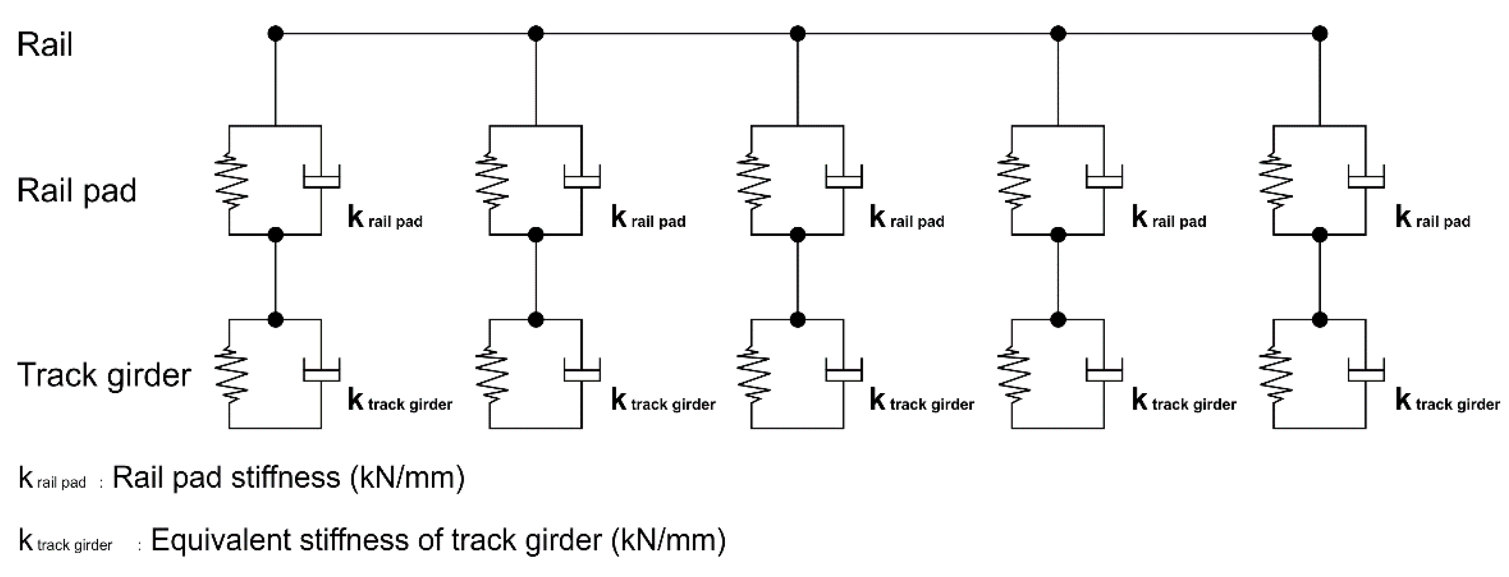
The track support stiffness of a direct fixation track supported by track girders has been found to be directly affected by the bending stiffness of the track girders [2]. Choi et al. [2] proposed an analytical model of the direct fixation track of the Yeongjong Grand Bridge that considers the equivalent spring stiffness as shown in Figure 13 [2].
The measured track support stiffness is the ratio of the maximum measured wheel load to the maximum vertical displacement of the rail; it can reflect the track support stiffness in the in-service condition [2,4,10]:
k =   F r a i l   m i d d r a i l   m i d ,
where k is the measured track support stiffness (kN/mm), Frail mid is the maximum wheel load (kN) at the center between the rail supporting points, and drail mid is the maximum rail displacement (mm) at the center between the rail supporting points [2,4,10].
In this study, the measured dynamic wheel loads on the measurement section were calculated and correlated to the rail displacement before and after rail pad replacement for each train type.
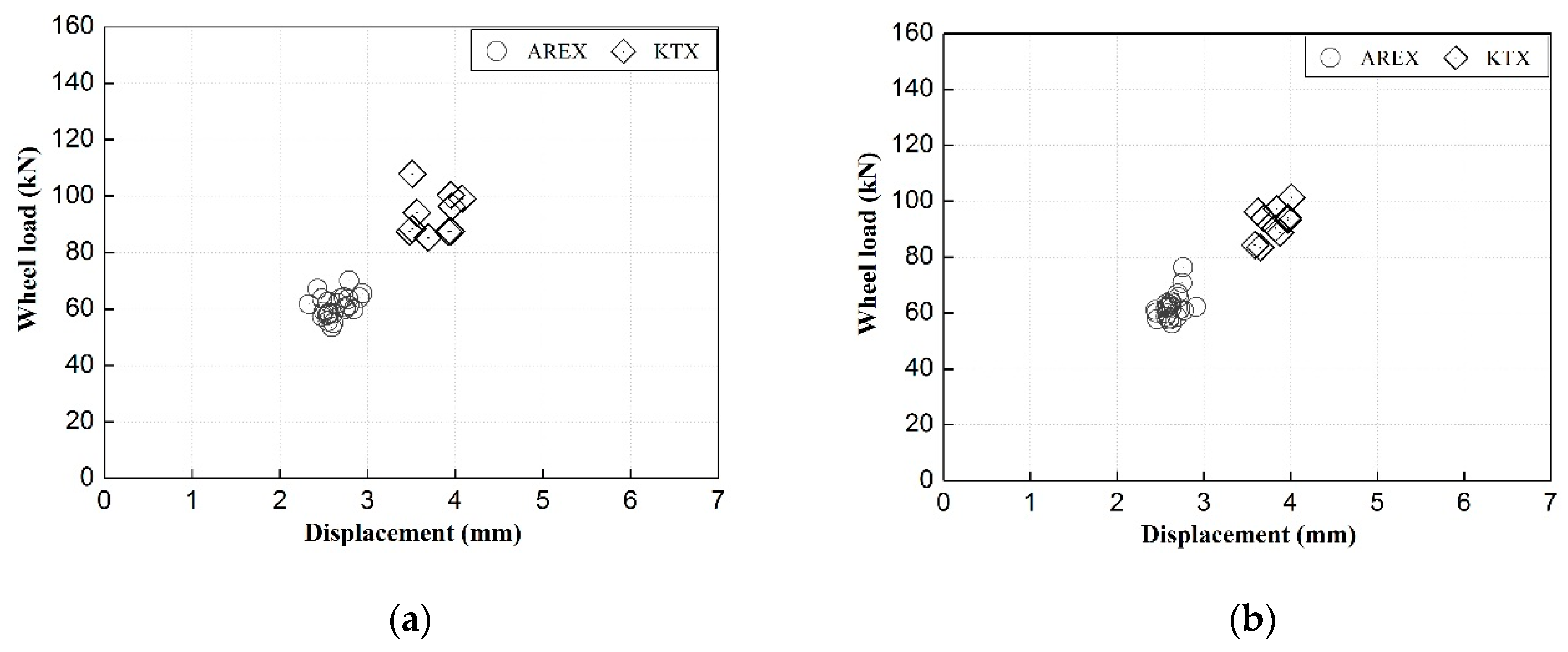
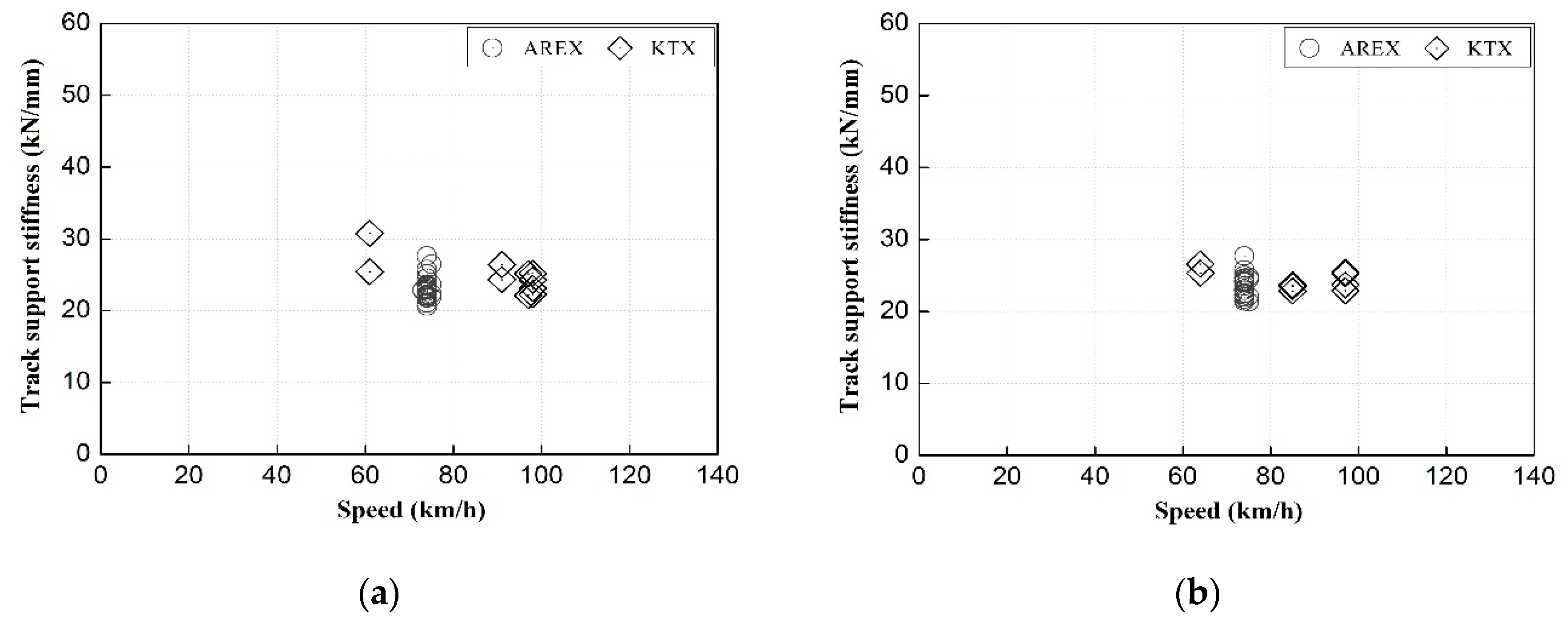
Figure 14 shows the dynamic wheel loads of all trains passing through the measurement section correlated to the rail displacements before and after rail pad replacement. Using the measured load–displacement data, the dynamic wheel load and displacement range for each train type in the measurement section was identified. Figure 15 shows the track support stiffness calculated based on the load–displacement measurements in Figure 14 before and after rail pad replacement.
The results in Figure 15 show that there was no clear change in the track support stiffness and no clear difference in the dynamic track support stiffness under different train speeds or before and after rail pad replacement. Therefore, it appeared that the use of old pads did not affect the track support stiffness of a direct fixation track system when accounting for the track girder bending stiffness.
In general, the track support stiffness of concrete or direct-connection-type track structures using soft elastic pads have been found to be directly affected by changes in the spring stiffness of the elastic pads [4,10]. Additionally, changes in the spring stiffness of the elastic pads and the subsequent changes in the track support stiffness have been observed to directly affect the track force and the dynamic behavior of the track [4,10]. Therefore, for conventional slab tracks, the timely replacement (maintenance) of elastic pads is important for securing track performance and soundness [4,10]. However, the hard rail pads used in the direct fixation track investigated in this study were intended for electrical insulation rather than track vibration reduction. Their relatively high spring stiffness had only a minor effect on track stiffness. In this study, a more realistic track support stiffness of the direct fixation track supported by girders was experimentally calculated and presented. However, the results did not indicate any significant change in the track pad status.

3. Laboratory Testing

The properties of the rail pad (SBR, styrene butadiene rubber) and assembly rail fastening system of the direct fixation track system of the Yeongjong Grand Bridge are presented in Table 3.
The laboratory testing of this study examined the changes in the spring stiffness of new and used pads under static, dynamic, and aging spring stiffness tests. The appropriate rail pad replacement periods were also investigated in terms of their function and usability based on the observed changes in the spring stiffness of the rail pad. Figure 16 shows the rail pad samples used in the laboratory testing, and Table 4 lists the test conditions.
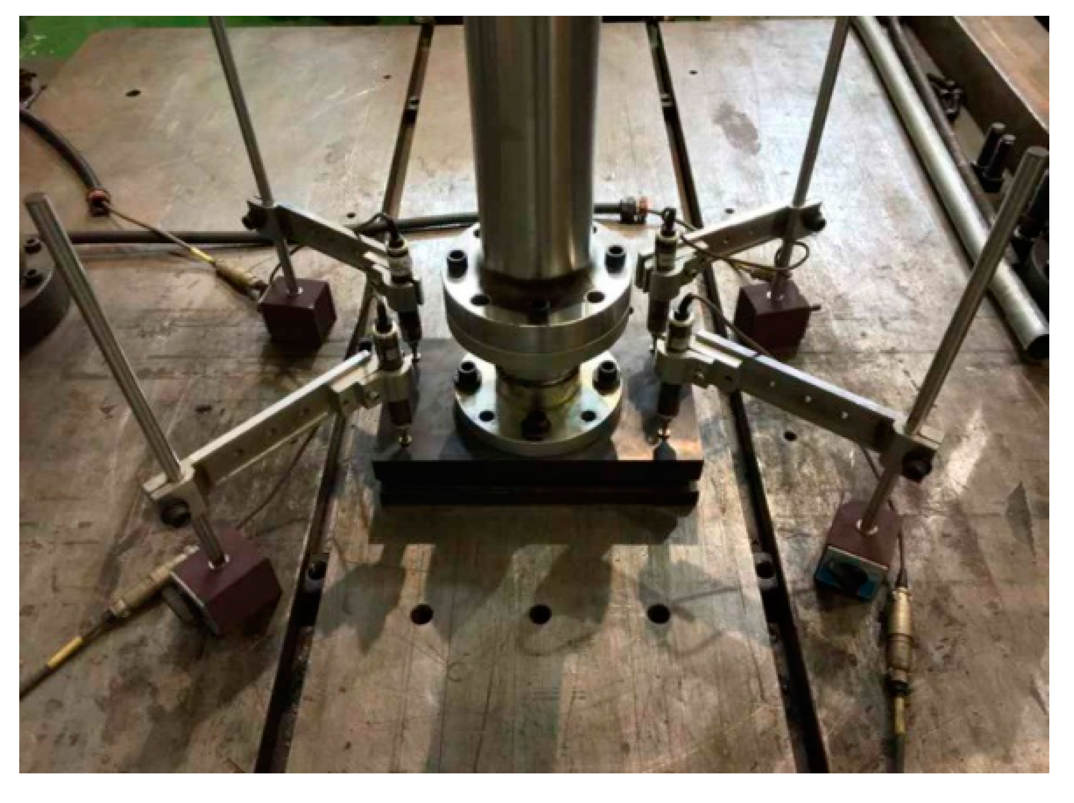
Static and dynamic vertical spring stiffness tests were conducted in accordance with the KRS (Korean Railway Standards) TR (track-rail) 0014-18(R) standard [18]. In these tests, each rail pad was fixed on top of the loading plate as shown in Figure 17. The zero-point setting was then performed after the linear variable differential transformers (LVDTs) were installed. The vertical displacement of the pad was measured at four points, and the results were used to prepare load–displacement curves. In the dynamic spring stiffness test, loading was performed 900 times in the 5–75 kN load range following a 4 Hz sine wave in accordance with KRS TR 0014-18(R) [18].
Aging tests were also conducted to account for the change in the spring stiffness of general rail pads using experimental conditions that accelerate the deterioration of rubber materials.
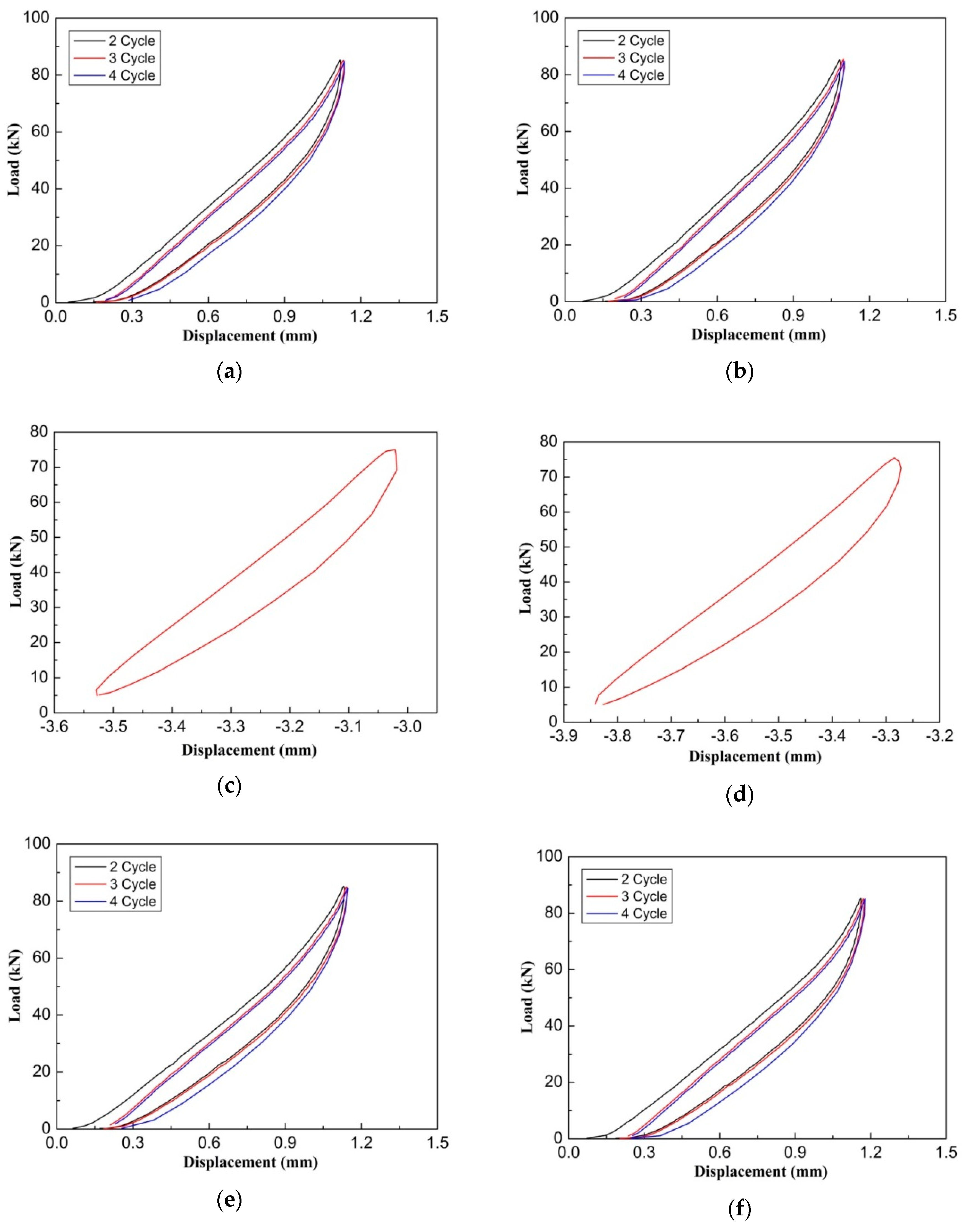
The aging test is a type of acceleration deterioration test that investigates the deterioration in material properties when the sample is placed in a special environment over an extended period of time. The test outcomes allowed for the analyses of changes in the spring stiffness of the rail pads due to deterioration under environmental conditions during their use. In this study, the static spring stiffness of the new and used rail pads were measured as per the static spring stiffness test after aging the rail pads for 72 h at a temperature of 70 ± 1°C, as temperature is the most important factor for identifying aging characteristics from among the various deterioration factors in accordance with KRS TR 0014-18(R) [18]. Figure 18 shows the load–displacement curves of the new and used pads obtained by the static, dynamic, and aging spring stiffness tests. As shown in Table 5, the direct fixation track structure rail pads exhibited only small differences in spring stiffness between the new and used rail pad before and after being subjected to the aging test.
As shown in Table 5, the differences between the static, dynamic, and aging spring stiffness test results for the new and used rail pads were found to be less than ±5% when subjected to an accumulated passing tonnage of 0.85 MGT. This indicates that the rail pads installed in the direct fixation track structure were not deformed or fractured by the temperature, period of use, or train load (accumulated passing tonnage).
Periodic replacement of soft rail pads is required to reduce track load and the damage caused by the deterioration of the rail pads. However, the rail pads of the direct fixation track system of the Yeongjong Grand Bridge evaluated in this study exhibited a displacement of approximately 0.5 mm when subjected to a load of 50 kN (static wheel load of AREX), and a displacement of approximately 0.94 mm when subjected to a load of 85 kN (static wheel load of KTX) based on the results of static spring stiffness tests. In contrast, the average displacement of the rail was 2.64 mm for AREX and 3.76 mm for KTX. The rail and track girder are coupled with the strong force of the fastener and exhibit integrated behavior [3]. The actual displacement of the rail was found to be 0.11 mm for AREX and 0.20 mm for KTX. This indicates that the actual displacement of the rail pad due to the wheel load of a passing train would be much smaller than that measured in the laboratory test results. Therefore, it was determined that the hard rail pads of a direct fixation track system yield very small displacement under actual service load conditions, and that the effect of fatigue on their spring stiffness is not significant.

4. Conclusions

In this study, laboratory testing and field measurements were conducted to analyze the influence of the corroded rail pads of direct fixation tracks on the dynamic track response, and assess the necessity of corroded rail pad replacement in terms of spring stiffness of the rail pad according to the corrosion in marine condition. The conclusions are as follows:
1) Soft pads are generally used for concrete track. However, the direct fixation track on the Yeongjong Grand Bridge uses hard pads. In this study, the bridge behaved flexibly without using a soft pad. Therefore, the use of hard pads did not affect usability.
2) There was no obvious change observed in the track support stiffness or in the dynamic track response according to the replacement of the corroded rail pads. This indicates that the corroded rail pads with high spring stiffness do not change the track support stiffness as they corrode. In addition, the difference in vibration due to the rail pad replacement was found to be insignificant.
3) As the results of laboratory testing (static, dynamic, and aging spring stiffness tests), it investigated that the rail pads of direct fixation track on the Yeongjong Grand Bridge were not significantly affected by load and temperature (as applied via the aging test). In addition, when tested in the aging test under more adverse conditions than the field conditions, the rail pads did not exhibit any significant changes in their spring stiffness. This confirms that the rail pads installed in the direct fixation track were not affected by corrosion (environmental conditions), or the loading period (passing tonnage) during their use.
4) As the rail pads of the direct fixation track in the Yeongjong Grand Bridge have adequately high spring stiffness values, they did not exhibit any response to dynamic wheel load due to passing trains; thus, even if a hard rail pad was used for the track on the Yeongjong Grand Bridge, the elastic behavior of the track was ensured according to the flexible bending behavior of the track type. This indicates that such rail pads were made of SBR materials that were not directly affected by the corrosion and the passing tonnage. Therefore, for the rail pads in this study, even though the rail pads were corroded in appearance, there was no functional problem, so it was not necessary to replace it. Furthermore, further studies are needed to measure and evaluate the deterioration caused by corrosion of the rail pads.
Author Contributions

Conceptualization, J.-Y.C. and K.-Y.L.; formal analysis, J.-Y.C.; investigation, J.-Y.C. and K.-Y.L.; data curation, J.-S.C. and J.-Y.C.; writing—original draft preparation, J.-Y.C. and S.-H.K.; writing—review and editing, S.-H.K. All authors have read and agreed to the published version of the manuscript.

Funding

This research received no external funding.

Conflicts of Interest

The authors declare no conflict of interest.

References

  1. Kaewunruen, S.; Remennikov, A.M. An alternative rail pad tester for measuring dynamic properties of rail pads under large preloads. Exp. Mech. 2008, 48, 55–64. [Google Scholar] [CrossRef] [Green Version]
  2. Choi, J.Y.; Chung, J.S.; Kim, S.H. Experimental study on track-bridge interactions for direct fixation track on long-span railway bridge. Shock Vib. 2019, 2019, 9. [Google Scholar] [CrossRef] [Green Version]
  3. Choi, J.Y.; Cung, J.S.; Kim, J.H.; Lee, K.Y.; Lee, S.G. Evaluation of behavior of direct fixation track and track girder ends on Yeongjong Grand Bridge. J. Korean Soc. Saf. 2016, 31, 45–51. [Google Scholar]
  4. Choi, J.Y. Qualitative Analysis for Dynamic Behavior of Railway Ballasted Track. Ph.D. Thesis, Technical University of Berlin, Berlin, Germany, 2014. [Google Scholar]
  5. Yunovich, M.; Thompson, N.G.; Balvanyos, T.; Lave, L. Highway bridges, Appendix D. In Corrosion Cost and Preventive Strategies in the United States; Federal Highway Administration: McLean, VA, USA, 2002. [Google Scholar]
  6. Darwin, D.; Browing, J.; Lindquist, W.D. Control of cracking in bridge decks: Observations from the field. Cem. Concr. Aggreg. 2004, 26, 1–7. [Google Scholar] [CrossRef]
  7. Frosch, R.J.; Labi, S.; Sim, C. Increasing Bridge Deck Service Life: Volume I—Technical Evaluation; Joint Transportation Research Program Publication No. FHWA/IN/JTRP-2014/16; Purdue University: West Lafayette, IN, USA, 2014. [Google Scholar]
  8. Cope, A.; Bai, Q.; Samdariya, A.; Labi, S. Assessing the efficacy of stainless steel for bridge deck reinforcement under uncertainty using Monte Carlo simulation. Struct. Infrastruct. Eng. 2013, 9, 634–647. [Google Scholar] [CrossRef]
  9. Obrecht, W.; Lamber, J.P.; Happ, M.; Oppenheimer-Stix, C.; Dunn, J.; Krüger, R. Rubber, 4. Emulsion Rubber. In Ullmann’s Encyclopedia of Industrial Chemistry; Wiley-VCH: Weinheim, Germany, 2011. [Google Scholar]
  10. Choi, J.Y. Influence of track support stiffness of ballasted track on dynamic wheel-rail forces. J. Transp. Eng. ASCE 2013, 139, 709–718. [Google Scholar] [CrossRef]
  11. Lee, D.U. Fatigue Effect Evaluation Method of Resilience Pad for Sleeper Floating Track. Ph.D. Thesis, Seoul National University of Science and Technology, Seoul, Korea, 2015. [Google Scholar]
  12. Park, G.H. The Temperature Effect for Fatigue Life of Polyurethane Resilient Pad in the Fastening System. Master’s Thesis, Seoul National University of Science and Technology, Seoul, Korea, 2011. [Google Scholar]
  13. Lim, H.J.; Sung, D.Y.; Park, Y.G. The fatigue life evaluation of rail on the concrete track of high speed railway by analysis of the vehicle/track interaction. J. Korean Soc. Civ. Eng. 2012, 32, 663–671. [Google Scholar] [CrossRef]
  14. Lei, X.; Zhang, B. Analysis of dynamic behavior for slab track of high-speed railway based on vehicle and track elements. J. Transp. Eng. ASCE 2011, 137, 227–240. [Google Scholar] [CrossRef]
  15. Korama, S.G.; Hussein, M.F.M.; Owen, J.S. Influence of preload and nonlinearity of railpads on vibration of railway tracks under stationary and moving harmonic loads. J. Low Freq. Noise Vib. Act. Control 2015, 34, 289–306. [Google Scholar] [CrossRef]
  16. Choi, J.Y.; Lee, D.W.; Park, Y.G. A study on the evaluation of track support stiffness on the various track type in urban transit. J. Korean Soc. Railw. 2011, 14, 262–270. [Google Scholar]
  17. Choi, J.Y.; Park, Y.G.; Lee, S.M. The evaluation of track impact factor on the various track type in urban transit. J. Korean Soc. Railw. 2011, 14, 248–255. [Google Scholar] [CrossRef]
  18. KRS TR 0014-18(R). Rail Fastening System. Korean Railway Standards. Available online: https://krs.krri.re.kr/krssearch/search_main.aspx?krmsType=11 (accessed on 30 June 2009).
Figure 1. Schematics of the direct fixation track system. (a) Direct fixation rail fastening system 1. insulation block, 2. leaf spring, 3. bolt, 4. anti-loosening nut, 5. washer, 6. insulation plate, 7. rail pad, and 8. adjustable pad; (b) side view of the track girder; and (c) cross section of the track girder [2,3].
Applsci 10 02245 g001
Figure 2. Photographs of corroded rail and pad. (a) Corroded track components and (b) corroded rail pad.
Applsci 10 02245 g002
Figure 3. Sensor installation. (a) Location of the measurement and (b) vertical and lateral wheel load strain gages, strain gages, vertical rail, and track girder displacements measured using displacement transducers mounted on a jig anchored at the side bridge inspection passage, which is not affected by the passing train [2].
Applsci 10 02245 g003
Figure 4. Measured dynamic wheel load by train type. (a) Before rail pad replacement and (b) after rail pad replacement.
Applsci 10 02245 g004
Figure 5. Comparison of the measured dynamic wheel load according to rail pad replacement. (a) Before rail pad replacement; (b) after rail pad replacement; and (c) dynamic wheel load fluctuation for before and after rail pad replacements.
Applsci 10 02245 g005
Figure 6. Measured lateral wheel load by train type. (a) Before rail pad replacement and (b) after rail pad replacement.
Applsci 10 02245 g006
Figure 7. Examples of measured vertical displacements of the track girder before and after rail pad replacement. (a) AREX and (b) KTX.
Applsci 10 02245 g007
Figure 8. Measured displacement of the rail by train type. (a) Before rail pad replacement and (b) after rail pad replacement.
Applsci 10 02245 g008
Figure 9. Measured displacement of the track girder by train type. (a) Before rail pad replacement and (b) after rail pad replacement.
Applsci 10 02245 g009
Figure 10. Measured lateral displacement of the rail by train type. (a) Before rail pad replacement and (b) after rail pad replacement.
Applsci 10 02245 g010
Figure 11. Measured bending stress of the rail by train type. (a) Before rail pad replacement and (b) after rail pad replacement.
Applsci 10 02245 g011
Figure 12. Comparison of the measured vertical acceleration of the rail and track girder. (a) Before rail pad replacement for AREX; (b) after rail pad replacement for AREX; (c) before rail pad replacement for KTX; and (d) after rail pad replacement for KTX.
Applsci 10 02245 g012
Figure 13. Spring stiffness model of a direct fixation track at the rail supporting points [2].
Applsci 10 02245 g013
Figure 14. Measured wheel load–track displacement according to train type. (a) Before rail pad replacement and (b) after rail pad replacement.
Applsci 10 02245 g014
Figure 15. Calculated track support stiffness according to train type (including the track girder bending stiffness). (a) Before rail pad replacement and (b) after rail pad replacement.
Applsci 10 02245 g015
Figure 16. Rail pad samples. (a) New rail pad and (b) used rail pad (corroded rail pad).
Applsci 10 02245 g016
Figure 17. Photograph of the rail pad spring stiffness test apparatus.
Applsci 10 02245 g017
Figure 18. Load–displacement curves. (a) Static test (new rail pad); (b) static test (used rail pad); (c) dynamic test (new rail pad); (d) dynamic test (used rail pad); (e) static test after aging tests (new rail pad); and (f) static test after aging tests (used rail pad).
Applsci 10 02245 g018
Table 1. Properties of the tested train.
AREXKTX
Train compositionTc1-M-M’-T1-M’-Tc2P-M-16R-M-P
Total length of train (m)120.90388.10
Axle distance (mm)22003000
Wheel diameter (mm)860920
Maximum speed (km/h)120330
Operational speed (km/h)73–7561–98
Effective beating distance (m)13.818.7
Designed wheel load (kN)5085
Note: Korea Train Express (KTX) = P (power car); M = motorized trailer; R = passenger car; Airport Railroad Express (AREX) = Tc (control car); M’ = motorized power car; T1, T2 = passenger cars.
Table 2. Ranges of the rail before and after rail pad replacements.
AREXKTX
BeforeAfterBeforeAfter
Wheel load (kN)55–7060–7185–10883–101
Lateral wheel load (kN)2–61–55–94–8
Vertical rail displacement (mm)2.48–2.942.44–2.753.48–4.083.59–4.01
Lateral rail displacement (mm)0.18–0.410.17–0.550.33–0.830.24–0.90
Track girder displacement (mm)2.62–3.152.61–2.923.56–4.243.52–4.15
Bending stress of rail (MPa)17–2717–2429–3631–39
Table 3. Design values of the spring stiffness of the rail pad for the direct fixation track.
Spring stiffness (kN/mm)
Rail padAssembly rail fastening system
Static80–90123.36
Dynamic120–140211.86
Table 4. Spring stiffness test conditions of rail pad.
StaticDynamicAging (static)
Loading rate50 kN/min 50 kN/min
Load range0–85 kN5–75 kN0–85 kN
Frequency 900 times (4 Hz)
Temperature (hour) 70 ± 1 ℃ (72 h)
Table 5. Rail pad spring stiffness test results.
Rail padSpring stiffness (kN/mm)Accumulated tonnage
(MGT)
StaticDynamicAging (static)
New (1)86.5127.984.3-
New (2)89.3138.586.7-
Used (1)89.5134.685.70.85
Used (2)93.6126.286.80.85