Article

A Shear-Wave Velocity Model in the City of Oued-Fodda (Northern Algeria) from Rayleigh Wave Ellipticity Inversion

by
Abdelouahab Issaadi
1,2,*,
Fethi Semmane
1,
Abdelkrim Yelles-Chaouche
1,
Juan José Galiana-Merino
2,3 and
Khalissa Layadi
1
1
Centre de Recherche en Astronomie, Astrophysique et Géophysique (CRAAG), 16340 Algiers, Algeria
2
University Institute of Physics Applied to Sciences and Technologies, University of Alicante, Crta. San Vicente del Raspeig, s/n, 03080 Alicante, Spain
3
Department of Physics, Systems Engineering and Signal Theory, University of Alicante, Crta. San Vicente del Raspeig, s/n, 03080 Alicante, Spain
*
Author to whom correspondence should be addressed.
Appl. Sci. 2020, 10(5), 1717; https://doi.org/10.3390/app10051717
Submission received: 30 November 2019 / Revised: 17 December 2019 / Accepted: 19 December 2019 / Published: 3 March 2020
(This article belongs to the Special Issue Mapping and Monitoring of Geohazards)

Abstract

:
The city of Oued-Fodda is located in north-central Algeria on the margins of the Middle-Cheliff Basin. This region has suffered several destructive earthquakes. The strongest was the 1980 El-Asnam earthquake (Ms7.3), whose causative fault was located about 1 km north of the city of Oued-Fodda. Therefore, a good knowledge of the soil characteristics in this city may allow a better evaluation of the seismic risk and help to minimize damages in the future. With this objective, a detailed microzonation study of Oued-Fodda has been carried out in this study. For that, the horizontal-to-vertical spectral ratio (HVSR) method has been applied on 102 sites along the city, estimating the soil fundamental frequencies and their corresponding amplitudes. Besides, the Rayleigh wave ellipticity inversion has been accomplished in order to estimate the corresponding Vs profiles and provide two cross-sections of the geology under the city. In the central part of the city, high-frequency peaks are observed, between 12.5 and 15 Hz, which correspond to impedance contrasts at shallow depth (<20 m). In the surrounding plain, two clear peaks are identified in the ranges 1.8–3.5 Hz (fundamental frequencies) and 6.5–15 Hz (secondary peaks).

1. Introduction

The north of Algeria is characterized by moderate to high seismicity, as a result of the convergence between the African and Eurasian plates. This seismicity is mainly concentrated on the margins of the Neogene basins [1]. In the Cheliff Basin, located in the northwestern part of Algeria, between the northern and southern Tellian Atlas mountain belts and lying parallel to the Africa-Eurasia plate boundary, in the approximately E‒W direction, the active deformation is mainly expressed by reverse faults oriented in a NE‒SW direction [1,2].
The Cheliff Basin is a synclinal depression filled with Mio-Plio-Quaternary deposits lying over a Mesozoic basement [2,3]. Due to its width (about 350 km from east to west), Perrodon [3], divided the basin into three sub-basins: the Low, the Middle and the High Cheliff Basin. The city of Oued-Fodda is situated in the western margins of the Middle Cheliff Basin (Figure 1).
During the past century, the Chlef region has experienced several destructive earthquakes, likethe 1934 Carnot (I0 = IX) earthquake [4], the 1954 Orléansville (Ms 6.7) earthquake [5] and the 1980 El-Asnam (Ms 7.3) earthquake [6], with an intensity of IX (MSK), all closeto the city of Oued-Fodda [6]. The epicenters of these three earthquakes are marked in Figure 1. The 1980 El-Asnam earthquake is the largest recorded event in Algeria, and the most destructive, with over 2600 victims and massive building damage. The causative fault is located about 1 km north of Oued-Fodda city.
Right after the El-Asnam earthquake, a geotechnical and geological study of the Chlef region was carried out by Woodward Clyde Consultants (WCC) [7] in order to assess the seismic risk in the region. More concretely, the study was conducted in the city of Chlef and eight surrounding cities, including Oued-Fodda city. As results, the WCC report provided different geotechnical and hydro-geological maps, and identified the liquefaction and landslide zones. The report also mentioned that site effects might be the cause of ground motion amplification.
Alternatively to geotechnical and geological techniques, seismic methods based on ambient vibrations are being widely used in recent decades (e.g., [8,9,10,11]). These methods are especially suitable for urban areas (non-destructive, low cost, quick implementation, etc.). There are two main categories of experimental techniques that use this kind of data: the first one is based on array measurements, and the second one is based on three-component single-station measurements (horizontal-to-vertical spectral ratio method, HVSR). In both approaches, an inversion of the estimated curve (dispersion curve in array measurements and HVSR curve in single-station technique) can be performed subsequently for estimating the associated S-wave velocity (Vs) profiles. In this sense, stochastic search methods such as genetic algorithms [12,13] and the neighborhood algorithm [14,15] are becoming increasingly popular in this kind of geophysical inverse problems.
In this regard, a complete site effect investigation has been recently conducted in the city of Chlef [16,17] in order to improve the study presented in the WCC report [7]. Standard spectral ratio, receiver functions and HVSR methods have been applied for both earthquakes and ambient vibrations. The soil fundamental frequencies (f0) have been identified, along with some subsurface characteristics (e.g., Vs profiles and depth to bedrock). In addition, one of the main results of Layadiet al. [16], is the interpretation of the bedrock as Mesozoic and not the outcropping Miocene rock. The great impedance contrast between the Miocene deposits and the Mesozoic basement is at the origin of the low frequency peak found everywhere in the city of Chlef.
According to theWCC report it turns out that the city of Oued-Fodda is built on and around a small knoll, which constitutes an Eocene bedrock outcrop covered with a thin sedimentary cover (<5 m). The city was first built on the knoll and then extended all around. The geotechnical maps included in the WCC Report [7] show that the area covering the knoll presents a low potential for earthquake-related building collapse. It also presents a low potential for landslides and liquefaction. The report also mentioned that only few building damages were observed in this zone.
In this study, we explore ambient vibrations data to identify the soil resonant frequencies and the corresponding amplitudes in Oued-Fodda city, using the HVSR method [18,19]. The second part of the present study aims to propose the Vs structure beneath the city, by using the Random Decrement (Raydec) technique [20] to extract the Rayleigh wave ellipticity (RWE) curves and subsequently, performing the RWE inversion [21] using the neighborhood algorithm [14,15]. The obtained results are compared to local and regional previous studies.
This study improves the one made by the WCC Report [7] in Oued-Fodda city and carries on the one made in the city of Chlef [16,17] for contributing to seismic hazard and risk mitigation in the region.

2. Geological Framework

The Middle Cheliff Basin is bordered onthe north by the Boumaad Mountains and tothe south by the Ouarsenis Mountains. Those mountain belts are essentially constituted of allochtonous Cretaceous and Jurassic formations [3,22]. Some similar formations outcrop in the central part of the basin, in the Temoulga, Rouina and Doui Massifs (Figure 1).
From a stratigraphical point of view, the sedimentary deposits begin with a detritic continental red series that we can observe at the margins of the basin. This layer is composed of brown marls and red clays and conglomerates of the Middle Miocene (Serravallian) [22]. This sedimentary layer is overlayed by thicker Tortonian (Upper Miocene) deposits constituted of sandstones, marls and limestones. The Messinian ones are formed essentially by blue marls with a maximum thickness of about 50 m [22]. The Pliocene formations are mainly represented by sandstones, marls, calcarenite and conglomerates. Those formations can reach a maximum thickness of 70 m [3].
North of the Oued-Fodda plain, the Pleistocene (Quaternary) deposits are essentially conglomeratic, and cover the Pliocene formations in discordance. From trench investigations near the Sara-El-Maarouf anticline, [23] observed that several unconformities exist through the Pleistocene and Holocene deposits. The later ones are constituted of sands, gravels, loams and clays.
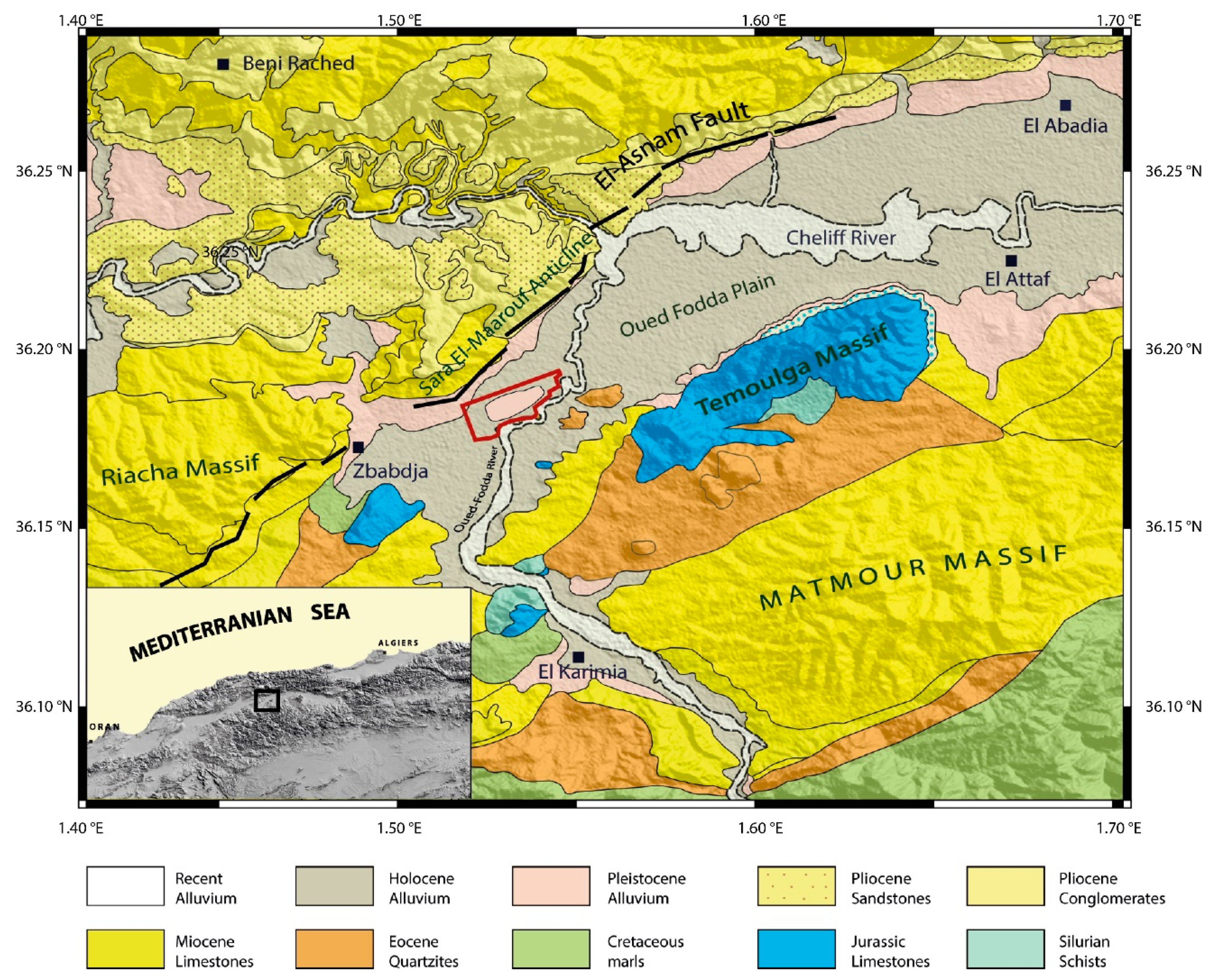
The city of Oued-Fodda is bounded tothe north by the Sara-El-Maarouf Anticline and tothe south by the Temoulga Massif and the Oued-Fodda River. The city lies some 4 to 16 m above the channel of the river [7]. The center of the city is built on a bedrock knoll overlayed by a thin layer (<5 m) of Pleistocene clays and conglomerates. The rest of the city is built on Holocene alluviums (Figure 2). The bedrock is represented by the Jurassic limestones and schists series that outcrops in the Temoulga massif 4 km east of the city. The depth to bedrock is very variable within the urban area. Aïfa and Idres, [24], assigned a depth of about 200 m, using gravimetric data.

3. Methodology

3.1. The Horizontal to Vertical Spectral Ratio (HVSR) Technique

Introduced by Nogoshiand Igarashi [18] and developed by Nakamura [19], the HVSR method using ambient vibrations data, most commonly known as the H/V method, links between the HVSR frequency peak and the fundamental resonant frequency of the soil. The H/V frequency peak is obtained by calculating the ratio between the amplitude spectra of the averaged horizontal and the vertical components of the ambient vibration recordings (e.g., [25]).
Although this method has proven its reliability in estimating the fundamental resonance frequency of the soil, it appears to under-estimate the amplification factor (e.g., [27,28]). This issue is mainly related to the relative contribution of the different types of seismic waves (e.g., [29]). However, the seismological community is still divided on whether it is the surface or the body waves that controls the H/V curves. It is important to notice that the contribution of body and surface waves depends mainly on the impedance contrast between the seismic bedrock and the sedimentary deposits, i.e., the H/V curve is mainly controlled by surface waves in case of a high impedance contrast, and by body waves in case of low impedance contrast [26].

3.2. Rayleigh Wave Ellipticity Curve Extraction and Inversion

The shape of the obtained HVSR curves depends strongly of the local conditions of the ambient vibrations recordings: energy ratio of Rayleigh/Love waves, body wave contribution, lateral variation of soil properties, source pattern, acquisition device, etc. Under these circumstances, the Rayleigh wave ellipticity can be detectable between the fundamental frequency peak and the first minimum at higher frequencies (e.g., [30]).
In recent years two different techniques have been mainly applied to reduce the contribution of body and Love waves in the calculation of the HVSR curve and provide a better estimation of the Rayleigh wave ellipticity: the H/V time-frequency analysis (HVTFA) [31] and the RayDec method [20]. The HVTFA technique uses the Continuous Wavelet Transform [32] to identify the P-SV waves and calculate the spectral ratio only with them. The RayDec method, based on the random decrement technique [33], uses the vertical component as a trigger and stacks a large number of horizontal and vertical signals in order to emphasize the Rayleigh waves with respect to the body and Love waves.
In this study, we have used the RayDec technique to extract the Rayleigh wave ellipticity curve from ambient vibration recordings for each zone of the study area.
The experimental curves are well reproduced with the RayDec and the HVSR techniques. However, particularly the RayDecellipticity curves better reproduce the right flank of the fundamental peak. To perform a reliable RWE inversion, we followed the strategy of Hobiger et al. [21], for ellipticity curves with or without singularities. For curves with singularity (one clear peak), the right flank of f0 is inverted. For curves with two singularities, the part from the right flank of f0 to the end of f1 is inverted. For ellipticity curves without singularities, the whole broad peak of the RWE curve is inverted if such peak exists. For a better constraint, a small part of the left flank of f0 is added to the inversion process.
The inversion of the RWE curves has been done using the Dinver software from the Geopsy package (www.geopsy.org) [34], which is based on the neighborhood algorithm [15]. The parameters that have to be set up before the inversion are: the number of sediments layers overlaying the bedrock, the interval of the variation of their thicknesses (hmin, hmax), densities (ρmin, ρmax), body wave velocities ranges (Vp and Vs), and Poisson ratio υ, ranging from 0.2 to 0.5 for soils and rocks.
The inversion has a strong trade-off between depth and velocity, impossible to resolve with RWE curves alone. Therefore, such an inversion works only in combination with some prior knowledge of superficial Vs profile [35]. In this way, it is recommended to constrain the initial soil model using previous information (waves velocity, densities, layer thicknesses, etc.) from other geotechnical and geophysical techniques (borehole, seismic refraction, etc.).
The inversion process produces a huge number of possible Vs profiles. For each generated soil model, the theoretical RWE curve is calculated, and then compared to the experimental one by a misfit parameter, which indicates how close the calculated curves are to the experimental ones.With all these considerations, the inversion of the HVSR curves is considered as a good tool to map the variation of Vs with depth.

4. Data Acquisition and Processing

4.1. Ambient Vibrations

A single station ambient vibration measurements campaign was conducted in the city of Oued-Fodda with a set of 125 points. For reliable results, the measurements were made following the advice found in the SESAME report [36]. The maximum distance between 2 adjoining stations was about 300 m. One hundred and two (102) recordings were selected for the analysis (Figure 3), the remaining recordings were excluded due to bad quality signals.
The distribution of the measurement points depends mainly on the different geological formations. Recordings were densified in the city center, on the bedrock knoll. Since the city is mainly growing southward, the recordings were also densified in the southern part (Figure 3).
A couple of TROMINO seismographs were used for the measurements, with a sampling rate of 512 samples per second. Due to the daytime traffic and human activity, measurements were performed during night time within the city center with an acquisition time of 20 min. In the areas outside the city, which mainly consists of farms and agricultural lands, acquisition time was between 20 min and 40 min, depending on human activity and weather conditions.
The data processing has been carried out using the Geopsy software (http://www.geopsy.org) [34]. All the recorded signals has been processed in the same manner: They have been divided into 5% cosine-tapered 40 s windows and the corresponding amplitude spectra have been smoothed using the Konno-Omachi algorithm [37] with a smoothing coefficient of 40. As a result, an HVSR curve is obtained by averaging the individual HVSR ratios of all the selected windows. For the consistency of the results, we have followed the criteria for clear and reliable experimental curves as recommended in the SESAME report [36].

4.2. Zonation of the Study Area Using Experimental HVSR Curves

Once the HVSR curves are obtained and the soil frequency peaks identified for each measurement site, a zonation map of the HVSR curves has been performed basing on the degree of similarity of the HVSR curves (Figure 4).
Four distinct zones have been identified as follows:
Zone 1:
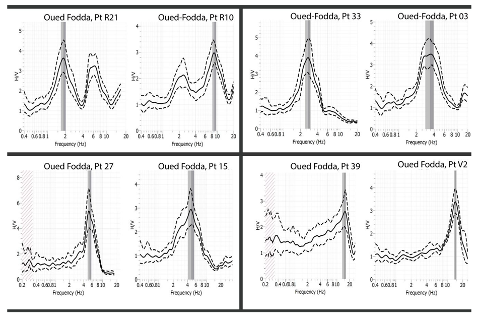
This zone includes HVSR curves with two peaks.The fundamental one, f0, ranges from 1.8 to 3 Hz, meanwhile the second peak, f1, ranges from 6.5 to 15 Hz. The corresponding amplitudes range from 2 to 4 for both peaks (e.g., Pt R21 and Pt R10 in Figure 5).
Zone 2:
This zone includes 10 recordings with clear f0 between 2.5 and 4 Hz, with amplitudes around 3.5 (e.g., Pt 03 and Pt 33 in Figure 5).
Zone 3:
A total set of 15 recordings with clear f0 between 5 and 7 Hz. The corresponding amplitudes vary from 2.5 to 6 (e.g., Pt 15 and Pt 27 in Figure 5).
Zone 4:
This zone covers the rock knoll in the central part of the city, with eight clear HVSR peaks between 12.5 and 15 Hz. The amplitudes range from 2.5 to 3.5 (e.g., Pt V2 and Pt 39 in Figure 5).
In some areas of the city, no peaks have been identified (flat curves) according to the criteria established in the SESAME report [36]. In these cases, it means that the obtained H/V curve lies between around 0.5 and 2.0, without any clear peak.

4.3. Geotechnical Information

The city of Oued-Fodda is poorly documented in terms of its sub-surface characteristics. The available data gives only information at very shallow depths (<20 m). The study presented by WCC [7] includes a set of eightgeotechnical boreholes in Oued-Fodda city with depths varying from 3 to 20 m. Talaganov et al. [38] analysed 10 seismic profiles in the cities of Chlef, Benirached and El Attaf. The results from the city of El Attaf may be transferred to Oued-Fodda which is located 8 km away (Figure 1) but on the same geological formation, so the obtained S-wave velocities may be also assigned to Oued-Fodda city.
From a geological point of view, the Oued-Fodda plain is dominated by two main formations. The first one consists of Holocene alluviums, which consists mainly of sands and clays. The WCC Report [7] assigns Vs values between 270 m/s and 300 m/s for Holocene clays and between 290 m/s and 375 m/s. for Holocene sands. The study reports a maximum thickness of 10 m. The second formation consists of Pleistocene clays and conglomerates. This formation occupies the major surface of the city area (Figure 2). The WCC Report [7] also assigns a Vs value of about 500 m/s for the Pleistocene red clays. According to [38], Vs for the Pleistocene deposits vary between 500 m/s and 600 m/s. The thickness of this sedimentary layer varies from 4 m in the central part of the city to 30 m in its northern and western parts [7]. A geotechnical borehole made by the AgenceNationale des RessourcesHydrauliques (ANRH) [39], north of the city shows a thickness of 25 m for this layer.
The Upper Miocene sediments, which underlie the Quaternary deposits, consist mainly of blue marls and limestones. Talaganov et al. [38], assigns a Vs value that ranges between 1050 m/s and 1070 m/s using the seismic refraction method, meanwhile Layadi et al. [17], provides values between 1000 m/s and 1300 m/s for the upper Miocene deposits by applying the RWE inversion.
There is not any geotechnical information about the Mesozoic basement in the Oued-Fodda region, even though this formation outcrops in the Temoulga Massif, 1 km east of the city. Layadi et al. [17], assigns a Vs value that ranges from 2000 m/s to 2600 m/s in the city of Chlef (about 15 km west of Oued-Fodda). A Vs value of 2800 m/s was assigned at a depth of about 1km in Chlef region by tomographic inversion [40].All the geotechnical information for the study area is summarized in Table 1.

4.4. Rayleigh Wave Ellipticity Curve

The estimation of the RWE curves has been done using the RayDec code [20], applying the same parameters of analysis for the four selected zones of Oued-Fodda city. That is, ambient vibration recordings of at least 20 min of length have been selected first and then, divided into two equal windows of 10 min. The individual RWE curves have been estimated for each window in 0.1–20 Hz frequency range, and subsequently the average RWE curve has been obtained for each zone, with the corresponding standard deviation (σ).

5. Results and Discussions

5.1. Soil Frequency Peaks and the Corresponding Amplitudes

The fundamental frequency variation map obtained from the H/V analysis is shown in Figure 6. The frequency values vary from 1.8 to 15 Hz. This wide frequency range is due to the different outcropping formations within the study area (Figure 2). The results show different types of curves: curves with one clear peak, curves with two clear peaks, and curves with no clear peaks (flat curves) (Figure 4). All around the city center, the predominant frequency varies between 1.8 and 3 Hz, with the existence of a secondary frequency peak between 6.5 and 15 Hz (Figure 7). This frequency peak should correspond to shallow impedance contrasts in the soil column. Frequencies between 5 and 7 Hz are identified in a small area in the eastern and northwestern parts of the city, like a transition zone between the first range and the higher frequencies (>10 Hz). The frequency peak values increase considerably towards the central part of the city, to reach a maximum value of 15 Hz on the most elevated point of the city, where the Ante-Neogene bedrock is at a very shallow depth [7].
Flat H/V curves (with amplitudes between around 0.5 and 2.0, without any clear peak) have been obtained from some points recorded in the center of the city and the Sidi-Amar cemetery in the southeastern side of Oued-Fodda (Figure 4 and Figure 6), which is assumed to be built on sandstones from Eocene age [7]. Some flat curves have also been obtained in the Sara-El-Maarouf anticline N-W of Oued-Fodda (Figure 4 and Figure 6). Flat HVSR curves reflect, among others, the absence of an impedance contrast in the soil column, which may mean that the signal had been recorded on a rock formation [36]. The amplitude of the fundamental frequency peaks range from 2.5 to 6 (Figure 6), and from 2 to 4 for the second peaks. The largest amplification factor is mainly observed west and south of the city center. Fortunately, in the city center where the constructions are essentially of a single floor (building frequency close to the soil fundamental frequency), the amplification factor is very low (<2).
The spatial distribution of the experimental HVSR curves shows that curves with only one clear peak are concentrated only in the central part of the Oued-Fodda city (mainly Zones 3 and 4), while HVSR curves with two frequency peaks are located all around the city center (Figure 4).
By comparing the results (Figure 4) of the HVSR technique with the geological map of the study area (Figure 2), we notice that the experimental H/V curves with one clear frequency peak are located on Pleistocene formation, while curves with two frequency peaks are on Holocene alluviums. The secondary peak at higher frequencies appears to be related to shallow impedance contrasts between the Holocene and the Pleistocene deposits.

5.2. Shear Wave Velocity Profiles

Since the city is built on two different geological formations, the Holocene and the Pleistocene alluvia (Figure 2), two different soil models have been used: A three layered model for the zone Z1, which covers the Holocene part, and a two layered model for the rest of the zones. The maximum thickness of each layer, along with the value ranges of the P-wave and S-wave velocities and the density, has been fixed by combining the values given by [7,38], As standard values for soils and rocks, the Poisson ratio ranges from 0.2 to 0.5 for all the layers. In order to better constrain the inversion and therefore, to have reliable results, the S-wave velocity of the topmost layer of the zones Z2, Z3, Z4 has been fixed to 615 m/s. For zone Z1, the S-wave velocity of the topmost layer has been set to 315 m/s.
The results of the RWE inversion are shown in Figure 8. The computed fundamental mode of the RWE curve of each zone is compared with the inverted part of the measurement Rayleigh wave ellipticity curve via misfit values. The S-wave velocity model corresponding to the minimum misfit value (the best model) is retrieved (Figure 8).

5.3. 2D Cross-Sections

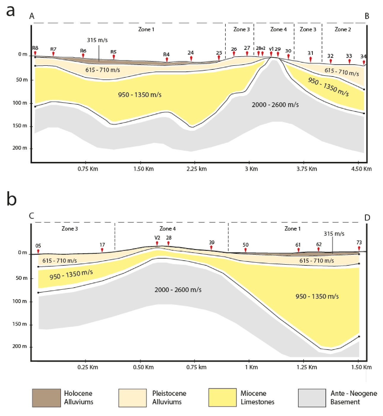
In order to show the variation of the estimated Vs profiles along the city, the results of the RWE inversion are illustrated in a couple of two-dimensional cross-sections (Figure 9). We have chosen the central part of the knoll as the intersection point of both profiles. In this way, the subsurface shape of this knoll is clearly identified. Figure 9a shows clearly that the Ante-Neogene bedrock outcrops in the central part of the knoll, between measurement points V1 and 29.
The shear-wave velocity for the topmost layer of the zone Z1, which consists of Holocene alluviums, ranges between 280 m/s and 330 m/s. The maximum thickness is 10 m (Figure 9). The velocity contrast between this layer and the underlying Pleistocene formation is responsible for the second peak at higher frequencies. Within the city area, the topmost layer consists of Pleistocene deposits. The thickness varies between 2 and 10 m in the center (Figure 9), where the bedrock is at very shallow depths, as reported by WCC Report [7]. In the rest of the study area, the thickness varies between 13 and 58 m (Figure 9). The shear-wave velocity ranges between 615 m/s to 710 m/s. The Vs values for the bottom sediment layer range between 950 m/s and 1350 m/s. The thickness varies from 13 to 16 m in the zone Z4, and from 40 to 162 m in the surrounding plain (Figure 9). The Vs values for the Ante-Neogene basement vary between and 2000 m/s and 2600 m/s. The velocity values are in agreement with the ones obtained by Layadi et al. [17].
The higher depths to bedrock are observed in the western and southern parts with a maximum value of 198 m (point 62, Figure 9b), which is not far from the 200 m obtained from gravity modeling [24].

6. Conclusions

Oued-Fodda, an inter-mountain city, is located in the western part of the Middle Cheliff Basin, which is the largest one in Algeria. With a population of over 40,000, Oued-Fodda is a good example of a growing urban city located close to a major active fault. In the present study, we focused on this city, one of the more damaged urban areas during the El-Asnam 1980 earthquake. In order to contribute to its site effects estimation and a deeper underground characterization, we used the HVSR method and the RWE inversion technique. The main results and conclusions are as follows:
  • The analysis of the ambient vibrations recordings using the HVSR method shows the predominance of single frequency peak curves in the center of the city (f0 ranges between 2.5 and 15 Hz). In the area surrounding the city center, two frequency peak curves are observed. The fundamental frequency, f0, ranges between 1.8 and 3.5 Hz. The second frequency peak, f1, which varies between 6.5 and 15 Hz, could be caused by the impedance contrast between the Holocene and Pleistocene deposits at shallow depths (<10 m).
  • The fundamental frequencies range between 1.8 and 15 Hz, this large variation is due to the local geology. The high frequency peaks (12.5–15 Hz) obtained on the knoll situated in the center of the city, along with the flat H/V curves confirm the assumption made by the WCC report [7] that this knoll is a bedrock outcrop.
  • From the inversion of the Rayleigh wave ellipticity curves, we obtained a four-layer model. The topmost layer consists of Holocene alluviums (Vs varies from 280 to 330 m/s), with a thickness less than 10 m. The second layer is composed of Pleistocene clays and conglomerates (Vs from 615 to 710 m/s). The bottom layer of the sedimentary deposits is composed of blue marls of Miocene age (Vs from 950 to 1350 m/s). The ante-Neogene bedrock, most probably composed of Mesozoic limestones and schists (Vs from 2000 to 2600 m/s), is at very shallow depths in the central part of the city (0–25 m). In the rest of the study area, the depth of the bedrock varies between 80 m and 198 m.
  • The results of the RWE inversion show clearly the existence of lateral variations of the shear-wave velocities and the sediments thickness in the Oued-Fodda city.
  • The obtained shear wave velocity models can be further used for strong ground motion simulation in the Middle Chellif Basin.
  • The largest amplification factor is about 6 and is mainly observed west and south of the city center. Fortunately, in the city center where the buildings are mainly single floor (building frequency close to the soil fundamental frequency), the amplification factor is very low (~2).
  • The city of Oued-Fodda is growing southward, where the largest thickness of the sedimentary cover is obtained. Site effects investigations should be taken into account, especially for growing cities located in high-level seismic hazard zones, in order to minimize potential building damages due to earthquakes. Since the north of Algeria is characterized by moderate to high seismicity, this study is a good example to follow for bigger Algerian cities.

Author Contributions

A.I. acquired and processed the data and wrote the paper; F.S. proposed the methodology, contributed on the interpretation of the results and reviewed the paper; A.Y.-C. reviewed and supervised the paper; J.J.G.-M. reviewed and supervised the paper by improving and editing the final manuscript drafts; K.L. helped with the data analyses and made the first corrections. All authors have read and agreed to the published version of the manuscript.

Funding

Research received no external funding.

Acknowledgments

We would like to thank the authorities of Oued-Fodda city for putting to our disposal all the data and information they had. We also want to thank our colleagues from the CRAAG station of the city of Chlef, for helping us with field measurements. We are thankful to the reviewers that helped us to improve the quality of the paper. Finally, a special thanks to all the persons that helped us to completethis work.

Conflicts of Interest

The authors declare no conflict of interest.

References

  1. Yelles-Chaouche, A.; Boudiaf, A.; Djellit, H.; Bracene, R. La tectonique active de la région nord-algérienne. Comptes Rendus Geosci. 2006, 338, 126–139. [Google Scholar] [CrossRef]
  2. Meghraoui, M.; Cisternas, A.; Philip, H. Seismotectonics of the lower Cheliff basin: Structural background of the El Asnam (Algeria) earthquake. Tectonics 1986, 5, 809–836. [Google Scholar] [CrossRef]
  3. Perrodon, A. Etude géologique des bassins sublittoraux de l’Algérie occidentale. Publ. Serv. Carte Géol. del’Algérie. NS Bull. 1957, 12, 328. [Google Scholar]
  4. Rothé, J. Le tremblement de terre d’Orléansville et la séismicité de l’Algérie. La Nat. 1955, 3237, 1–9. [Google Scholar]
  5. McKenzie, D. Active tectonics of the Mediterranean region. Geophys. J. Int. R. Astron. Soc. 1972, 30, 109–185. [Google Scholar] [CrossRef] [Green Version]
  6. Ouyed, M. Le Tremblement De Terre d’El Asnam Du 10 Octobre 1980: Étude Des Répliques. Ph.D. Thesis, Universite Scientifique et Medicale de Grenoble, Grenoble, France, 1981. [Google Scholar]
  7. Woodward-Clyde-Consultants. Seismic Microzonation of Ech-Chellif Region, Algeria; Report Prepared for Organisme de Controle Technique de la Construction (CTC); CTC: Algiers, Algeria, 1984. [Google Scholar]
  8. Parolai, S.; Bormann, P.; Milkereit, C. Assessment of the natural frequency of the sedimentary cover in the Cologne area (Germany) using noise measurements. J. Earthq. Eng. 2001, 5, 541–564. [Google Scholar] [CrossRef]
  9. Mundepi, A.; Galiana-Merino, J.; Lindholm, C. Soil characteristics and site effect assessment in the city of Delhi (India) using H/V and f–k methods. Soil Dyn. Earthq. Eng. 2010, 30, 591–599. [Google Scholar] [CrossRef]
  10. Rosa-Cintas, S.; Galiana-Merino, J.; Molina-Palacios, S.; Rosa-Herranz, J.; García-Fernández, M.; Jiménez, M. Soil characterization in urban areas of the Bajo Segura Basin (Southeast Spain) using H/V, F–K and ESAC methods. J. Appl. Geophys. 2011, 75, 543–557. [Google Scholar] [CrossRef]
  11. Rosa-Cintas, S.; Clavero, D.; Delgado, J.; López-Casado, C.; Galiana-Merino, J.J.; Garrido, J. Characterization of the shear wave velocity in the metropolitan area of Málaga (S Spain) using the H/V technique. Soil Dyn. Earthq. Eng. 2017, 92, 433–442. [Google Scholar] [CrossRef]
  12. Sen, M.K.; Stoffa, P.L. Nonlinear one-dimensional seismic waveform inversion using simulated annealing. Geophysics 1991, 56, 1624–1638. [Google Scholar] [CrossRef]
  13. Sambridge, M.; Drijkoningen, G. Genetic algorithms in seismic waveform inversion. Geophys. J. Int. 1992, 109, 323–342. [Google Scholar] [CrossRef] [Green Version]
  14. Sambridge, M. Geophysical inversion with a neighbourhood algorithm—I. Searching a parameter space. Geophys. J. Int. 1999, 138, 479–494. [Google Scholar] [CrossRef] [Green Version]
  15. Wathelet, M. An improved neighborhood algorithm: Parameter conditions and dynamic scaling. Geophys. Res. Lett. 2008, 35. [Google Scholar] [CrossRef] [Green Version]
  16. Layadi, K.; Semmane, F.; Yelles-Chaouche, A. Site-Effects Investigation in the City of Chlef (Formerly El-Asnam), Algeria, Using Earthquake and Ambient Vibration Data. Bull. Seismol. Soc. Am. 2016, 106, 2185–2196. [Google Scholar] [CrossRef]
  17. Layadi, K.; Semmane, F.; Yelles-Chaouche, A. S-wave velocity structure of Chlef City, Algeria, by inversion of Rayleigh wave ellipticity. Near Surf.Geophys. 2018, 16, 328–339. [Google Scholar] [CrossRef]
  18. Nogoshi, M.; Igarashi, T. On the amplitude characteristics of ambient noise (Part 2). J. Seismol. Soc. Jpn. 1971, 24, 26–40. [Google Scholar]
  19. Nakamura, Y. A method for dynamic characteristics estimation of subsurface using microtremor on the ground surface. Railw. Tech. Res. Inst. Q. Rep. 1989, 30, 25–33. [Google Scholar]
  20. Hobiger, M.; Bard, P.Y.; Cornou, C.; Le Bihan, N. Single station determination of Rayleigh wave ellipticity by using the random decrement technique (RayDec). Geophys. Res. Lett. 2009, 36. [Google Scholar] [CrossRef]
  21. Hobiger, M.; Cornou, C.; Wathelet, M.; Giulio, G.D.; Knapmeyer-Endrun, B.; Renalier, F.; Bard, P.-Y.; Savvaidis, A.; Hailemikael, S.; Le, B.N. Ground structure imaging by inversions of Rayleigh wave ellipticity: Sensitivity analysis and application to European strong-motion sites. Geophys. J. Int. 2012, 192, 207–229. [Google Scholar] [CrossRef] [Green Version]
  22. Meghraoui, M. Etude Neotectonique de la Region nord-est d’El Asnam: Relation avec le Seisme du 10.10.1980. Ph.D. Thesis, Univ. Paris VII, Paris, France, 1982. [Google Scholar]
  23. Meghraoui, M. Géologie des Zones Sismiques du Nord de l’Algérie: Paléosismologie, Tectonique Active et Synthèse Sismotectonique. Ph.D. Thesis, Univ. Paris-Sud, Paris, France, 1988. [Google Scholar]
  24. Aïfa, T.; Idres, M. Indentation model usinggravityanomaly and anisotropy of magneticsusceptibility: Consequences on nappe rotations in the Chélif Basin, Algeria. Open Geol. J. 2010, 4, 105–116. [Google Scholar]
  25. Bonnefoy-Claudet, S.; Cotton, F.; Bard, P.-Y. The nature of noise wavefield and its applications for site effects studies: A literature review. Earth Sci. Rev. 2006, 79, 205–227. [Google Scholar] [CrossRef]
  26. Brives, A. Les Terrains Miocènes du Bassin du Chélif et du Dahra; Imprimerie, P. Fontana & Cie: Algiers, Algeria, 1897. [Google Scholar]
  27. Oubaiche, E.H.; Chatelain, J.L.; Bouguern, A.; Bensalem, R.; Machane, D.; Hellel, M.; Khaldaoui, F.; Guillier, B. Experimental relationship between ambient vibration H/V peak amplitude and shear-wave velocity contrast. Seismol. Res. Lett. 2012, 83, 1038–1046. [Google Scholar] [CrossRef]
  28. Mucciarelli, M.; Gallipoli, M.R.; Arcieri, M. The stability of the horizontal-to-vertical spectral ratio of triggered noise and earthquake recordings. Bull. Seismol. Soc. Am. 2003, 93, 1407–1412. [Google Scholar] [CrossRef]
  29. Rosa-Cintas, S.; Galiana-Merino, J.; Rosa-Herranz, J.; Molina, S.; Martínez-Esplá, J. Polarization analysis in the stationary wavelet packet domain: Application to HVSR method. Soil Dyn. Earthq. Eng. 2012, 42, 246–254. [Google Scholar] [CrossRef]
  30. Fäh, D.; Kind, F.; Giardini, D. A theoretical investigation of average H/V ratios. Geophys. J. Int. 2001, 145, 535–549. [Google Scholar] [CrossRef] [Green Version]
  31. Poggi, V.; Fäh, D. Estimating Rayleigh wave particle motion from three-component array analysis of ambient vibrations. Geophys. J. Int. 2010, 180, 251–267. [Google Scholar] [CrossRef] [Green Version]
  32. Daubechies, I. Ten Lectures on Wavelets. Comput. Phys. 1992, 6, 697. [Google Scholar] [CrossRef] [Green Version]
  33. Asmussen, J.C. Modal Analysis Based on the Random Decrement Technique: Application to Civil Engineering Structures. Ph.D. Thesis, Department of Mechanical Engineering, Aalborg University, Aalborg, Denmark, 1997. [Google Scholar]
  34. Wathelet, M. Array Recordings of Ambient Vibrations: Surface-Wave Inversion. Ph.D. Thesis, Liége University, Liège, Belgium, 2005. [Google Scholar]
  35. Castellaro, S.; Mulargia, F. VS 30 estimates using constrained H/V measurements. Bull. Seismol. Soc. Am. 2009, 99, 761–773. [Google Scholar] [CrossRef]
  36. Guidelines for the Implementation of the H/V Spectral Ratio Technique on Ambient Vibrations. SESAME European Research Project, Deliverable D23.12 (WP12). Available online: Ftp://ftp.geo.uib.no/pub/seismo/SOFTWARE/SESAME/USER-GUIDELINES/SESAME-HV-User-Guidelines.pdf (accessed on 20 November 2019).
  37. Konno, K.; Ohmachi, T. Ground-motion characteristics estimated from spectral ratio between horizontal and vertical components of microtremor. Bull. Seismol. Soc. Am. 1998, 88, 228–241. [Google Scholar]
  38. Talaganov, K.; Aleksovski, D.; Milutinovic, Z.; Ameur, B.; Arsovski, M.; Jancevski, J.; Andreevski, V. Studies for elaboration of the code for repair and strengthening of damaged buildings in the region of El Asnam: Engineering geology, geotechnical and geophysical characteristics of the town of El Asnam and other sites. Rep. IZIIS 1982, 82-55. [Google Scholar]
  39. ANRH (Agence Nationale des Ressources Hydrauliques). Available online: http://www.anrh.dz (accessed on 29 September 2019).
  40. Bellalem, F. Identification de la Structure Tridimensionnelle en Vitesse Sismique dans la Région de Chlef (Algérie) à Partir des Données Sismologique par tomoDD et LOTOS. Ph.D. Thesis, Univ. Ferhatabbas, Setif, Algeria, 2015. [Google Scholar]
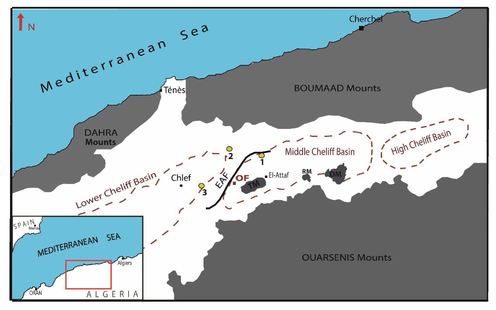
Figure 1. Situation of the Middle Cheliff Basin. Yellow circles represent the major earthquakes in the area: (1) The 1934 Carnot (I0 = IX) earthquake, (2) The 1954 Orléansville (Ms 6.7) earthquake, (3) The 1980 El-Asnam earthquake (Ms 7.3). EAF: El-Asnam fault (black line). OF: Oued-Fodda city. TM: Temoulga Massif. RM: Rouina Massif. DM: Doui Massif.
Applsci 10 01717 g001
Figure 2. Geological map of Oued-Fodda. Red line is the limit of the city. Thick black lines are the surface traces of the El-Asnam Fault (modified from [26]).
Applsci 10 01717 g002
Figure 3. HVSR measurement points (yellow squares) and boreholes (red dots). The two black lines (AB and CD) indicate two cross-sections of Vs profiles.
Applsci 10 01717 g003
Figure 4. Zonation map of the HVSR curves. Black dots represent the measurement points, and red dots represents the HVSR flat curves.
Applsci 10 01717 g004
Figure 5. Some examples of the obtained HVSR curves. The gray vertical bands show the fundamental frequency peaks with its standard deviation.
Applsci 10 01717 g005
Figure 6. (a) Fundamental frequencies obtained from the HVSR analysis. Black dots represent the measurement points, while white dots represent the flat HVSR curves. (b) The corresponding amplification factors map.
Applsci 10 01717 g006
Figure 7. (a) Mapping of secondary frequency peaks, f1. (b) Corresponding amplification factors obtained from the HVSR analysis. The thick black line is the El-Asnam Fault (EAF). The black grid is the city map and roads.
Applsci 10 01717 g007
Figure 8. Examples of the estimated shear-wave velocity profiles for each zone. The left panels represent the computed fundamental mode of Rayleigh wave ellipticity curve (dark grey curve), and the inverted part of the calculated Rayleigh wave ellipticity (black dotted curve) for each zone linked via misfit values. The right panels represent the obtained shear-wave velocity models. The model in black corresponds to the one with the minimum misfit, while dark grey corresponds to models with misfit +10%. The rest of the generated models are represented in light grey.
Applsci 10 01717 g008
Figure 9. (a) Two-dimensional N-S cross-section (CD profile in Figure 3). (b) Two-dimensional ENE-WSW cross-section (AB profile in Figure 3). Red diamonds show the ambient noise measurement points.
Applsci 10 01717 g009
Table 1. Geological and geotechnical information for each zone of the study area.
ZoneEpochThickness (m)Vp (m/s)Vs (m/s)Density (Kg/m3)References
Z1Holocene0–40600–10003151700–1900 [7]
Pleistocene10–701800–2000500–7501950–2200 [38]
Miocene40–1702500–3500900–14002100–2400 [39]
Z2Pleistocene0–501800–2200500–8001950–2250 [7]
Miocene30–1302500–3500900–14002100–2400[38]
Z3Pleistocene0–401800–2000500–7501950–2200[7]
Miocene20–602500–3500900–14002100–2400 [38]
Z4Pleistocene0–151500–2000450–7501900–2200 [7]
Miocene10–302500–3500900–14002100–2400 [38]