Article

Five-Axis Freeform Surface Color Printing Technology Based on Offset Curve Path Planning Method

1
The State Key Laboratory of Fluid Power and Mechatronic Systems, College of Mechanical Engineering, Zhejiang University, Hangzhou 310027, China
2
Key Laboratory of 3D Printing Process and Equipment of Zhejiang Province, College of Mechanical Engineering, Zhejiang University, Hangzhou 310027, China
*
Author to whom correspondence should be addressed.
Appl. Sci. 2020, 10(5), 1716; https://doi.org/10.3390/app10051716
Submission received: 31 January 2020 / Revised: 16 February 2020 / Accepted: 26 February 2020 / Published: 3 March 2020
(This article belongs to the Section Mechanical Engineering)

Abstract

:
Great progress has been made in 2D color printing with inkjet technology, and mature related products have come out, but there still exists great developmental space in 3D color printing. Therefore, a new path planning method based on the offset curve for 3D inkjet technology is proposed in this paper. Offset curves are generated on a freeform surface with geodesic equidistance, and then points for color printing are generated along the offset curves. In this paper, the principle of color printing technology with a 5-axis platform and the offset curve path planning (OCPP) method are presented. In addition, comparisons between the OCPP and adaptive filling algorithm based on the section method (AFSM) have been implemented. The OCPP significantly increased the rate of the theoretical filling area from 0.89 to 0.99 on a freeform surface.

1. Introduction

2D color printing technology has made great progress, such as multicolor printing technology for planes, but 3D color printing technology is still at an exploratory stage. There are three main traditional surface printing technologies, including curved surface screen printing [1], pad printing [2], and waterless offset printing [3]. The above technologies are usually applied to cylindrical surfaces and need to be prepared with a corresponding printing plate, which limits them to specific surface patterns. Since these, 3D inkjet technology [4] and 3D rapid prototyping technology [5,6] have been developed. Gazeau et al. [7] developed a 5-degree-of-freedom (DOF) robot and tried to print on surfaces, but it was mainly applicable to large and vertical flat surfaces. Zhang et al. [8,9] proposed a method by thermoforming a thin plastic sheet with texture to adhere seamlessly onto a surface. However, that technology is currently at the exploratory stage due to the complex computation and equipment limitations. Solid Terrain Modeling (STM) company [10] in the U.S. has developed a set of equipment that can make color geographical models. The system includes a carving machine and a coloring device, which can provide users with models containing 3D geographic information and surface color information. The system is mainly applied to the military sandbox and geographical models. Some devices with 3D rapid prototyping technology were launched to make colorful parts, such as Objet500 Connex3 [11] of Stratasys. However, they are not widely used because of their high price. To the best of our knowledge, there is no commercial color printer for freeform surfaces yet. However, in many rapid prototyping technologies, fused deposition modelling (FDM) is becoming more and more popular due to its simple structure and low price. Generally, FDM is mainly used for producing a monochromatic workpiece. With the increasing demand for color parts, many researchers have started to study multi-color FDM technology. There are three main ways:
1 Multi-nozzle
The multi-nozzle system integrates multiple nozzles, each of which can print one kind of filament with one color. Different nozzles are selected according to different times and positions. In 2014, ORD Solutions [12] in Canada developed a color 3D printer, RoVa3D, with five nozzles, which integrates five printing heads and can print models with multiple colors. However, the mechanical structure of the printing module of the device is complex, and the system does not involve the mixing of pigments, and can only print models with up to five colors.
2 Mixing filaments
The basic principle of the mixing system is based on the three pigments with primary colors (red, green, blue). Through mixing filaments with primary colors according to different proportions, the mixed filaments of the target color can be produced to achieve colorful printing. In 2012, James [13] developed a printing head that supported mixing two colors. Its color mixing effect is still not satisfactory. When the 3D full-color desktop printer of the Cube Series was launched by the 3DSYSTEMS Company in 2015, the printed colorful workpiece had a good effect, but the printing effect of that printer for multi-color models with sudden color changes is still not ideal.
3 Dyeing filaments
Its basic principle is to dye the filament while the filament is still in the melting state, thus forming a colorful model. In 2014, a research and development team at the University of Wisconsin Madison [14] developed a dye 3D printer, Spectrom. The printer realizes 3D color printing by dyeing the transparent polymer filaments. However, that printer has special requirements for materials and dyeing inks. The commonly used materials (e.g., ABS (acrylonitrile butadiene styrene) and PLA (polylactic acid)), do not meet the printing requirements, which limits the printer’s promotion.
In our previous work [15], we proposed the adaptive filling algorithm based on the section method (AFSM) to realize color printing on a freeform surface with multi-color FDM technology. A white model is printed first and then its surface is colored with pigment ink. However, the AFSM is not the best solution, since the printing points cannot fully fill the theoretical filling area (TFA). Therefore this paper presents the five-axis single point printing technology and a new path planning method based on offset curve (OCPP) for color printing. Much attention has been given to curve offsetting by various researchers in the field of computer-aided design [16,17,18]. For example, Choi and Park [19] studied the curve offset based on a polygonal chain.

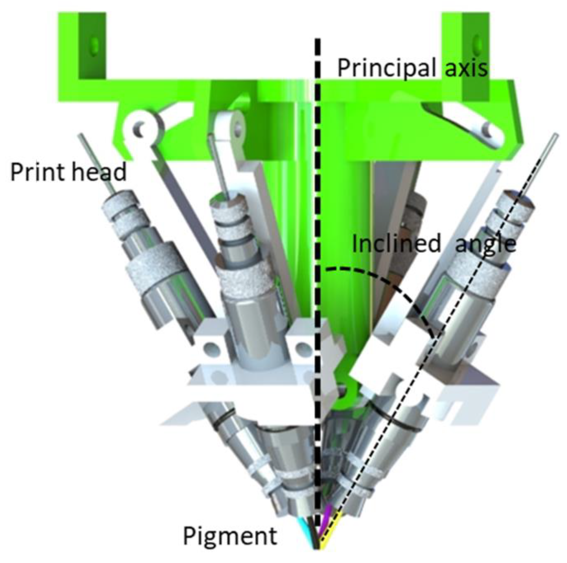
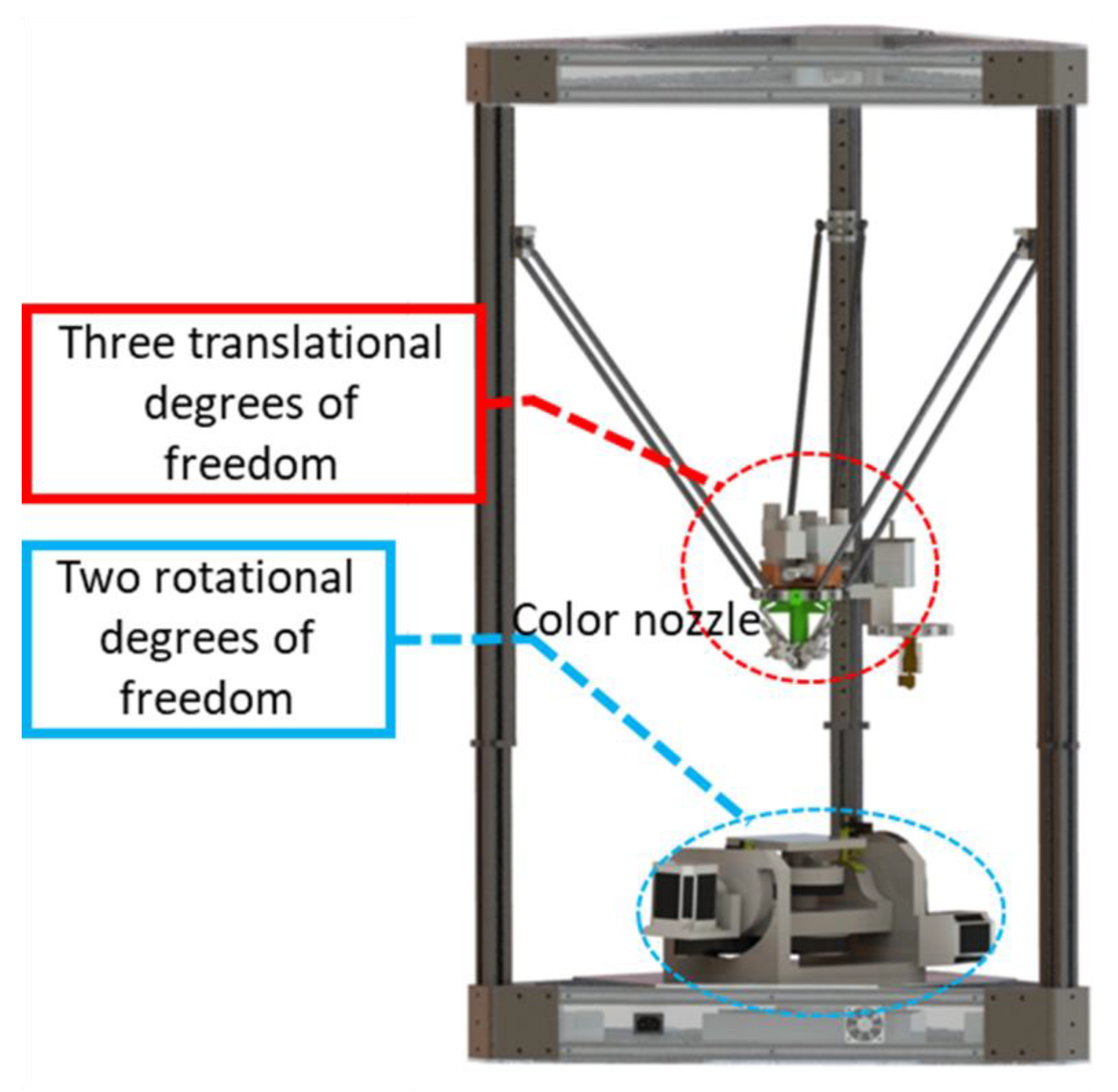
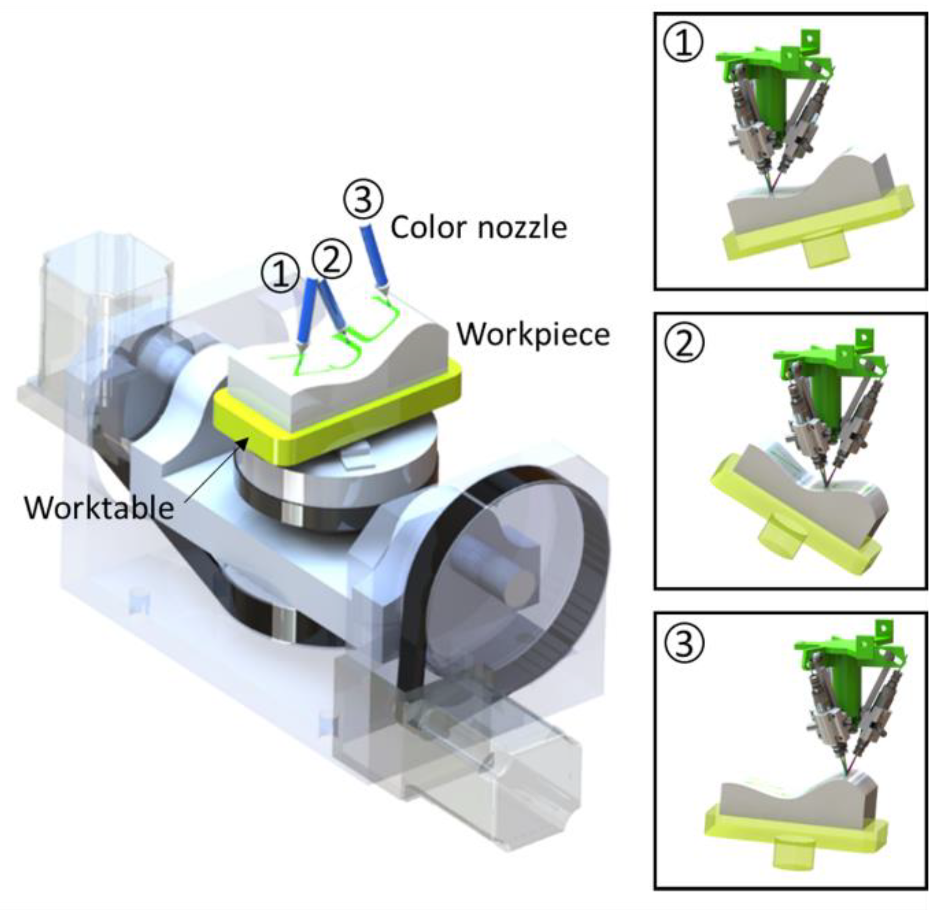
2. Five-Axis Single Point Color Printing Technology

Single-point printing. As shown in Figure 1, the color nozzle consists of four printing heads, which can print cyan, magenta, yellow, and black (CMYK) pigments, respectively. The printing heads are aslant fixed, and the inclination angles of the print heads are consistent, resulting in the mixed pigment printed on a single point. By adjusting the ratio of the CMYK pigments on a single point, the full-color printing point can be obtained. The color points can be printed on a surface point-by-point to form the patterns, as shown in Figure 2.
Five-DOF printing. As shown in Figure 3, the structure of a traditional delta printer can provide three translational DOFs. A two-dimensional turntable can provide two rotational DOFs. Therefore, a five-DOF platform was established to realize color printing for a freeform surface.
Normal direction printing mode. The printing direction is along the normal vector of the surface. As shown in Figure 4, the principal axis of the color nozzle is always perpendicular to the freeform surface, and the convergence point of the four printing heads needs to be right on the surface. Therefore, the distance between the nozzle and the surface is kept at a constant value, which guarantees the roundness and the size of the printing points.

3. Path Planning Algorithm Based on the Offset Curve

The VRML (virtual reality modeling language model) [20] is used in our system, since it contains both the geometric data and the color data. In our previous work [15], the adaptive filling algorithm based on the section method (AFSM) was used, which includes two parts, the adaptive-thickness slice (ATS) and the self-adaptive printing filling (SAPF). However, the AFSM is not the best solution, since the printing points could not fully fill the theoretical filling area (TFA). Therefore, a new method based on offset curve path planning (OCPP) is proposed.

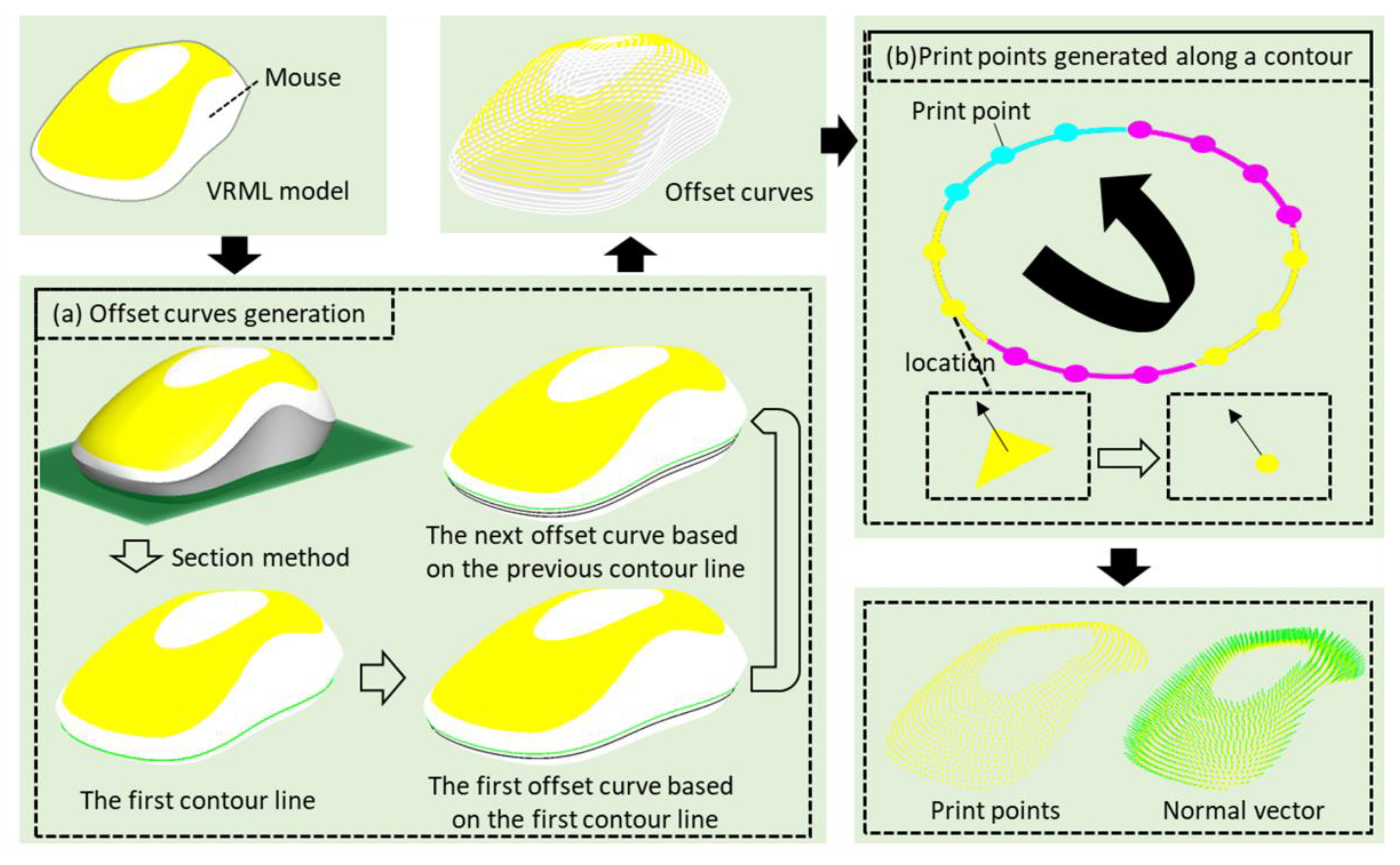
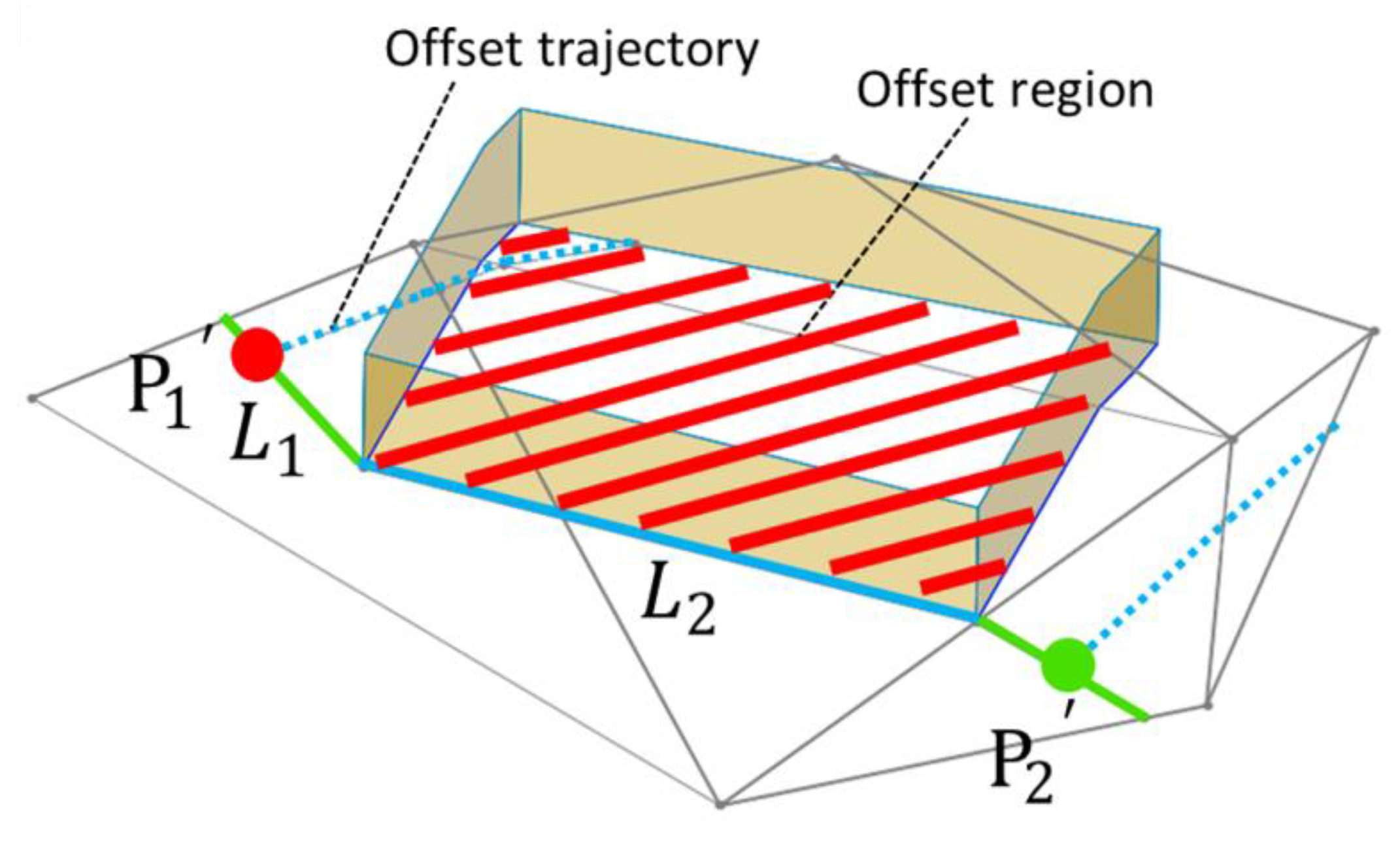
3.1. Process of the OCPP

Figure 5 shows the process of the OCPP. The first step is to generate offset curves on the surface, and then printing points are generated along the offset curves. Finally, the coordinates and color information of the printing points can be obtained based on the triangular facets where the printing points are located.
The OCPP focuses on the offset curve generation. As shown in Figure 5a, firstly, the first contour line is generated at the bottom of the model by the section method (slicing the model on a horizontal plane). Based on the first contour line, the first offset curve is generated by an offset algorithm. Then, the next offset curve is calculated according to the previous offset curve until the offset curves cover the entire surface. How to generate the next offset curve from a known contour is detailed below.

3.2. Generation of the Offset Curve on a Triangular Mesh Surface

The generation of the offset curve is based on a triangular mesh surface. Holla et al. [21] proposed an incremental approach to compute the offset curve. Their method completely eliminates the formation of local self-intersections. However, small and irregular triangles would increase the error of the offset accuracy and greatly reduce the stability of the algorithm. Therefore, we propose a method of curve offsetting based on a discrete point (CODP).
The core idea of CODP is to create a series of discrete points on the original curve, and the offset curve is generated by the offset calculation of the discrete points. This method could effectively avoid the occurrence of local self-intersection and global self-intersection. Even on complex triangular mesh, the method still has good stability.

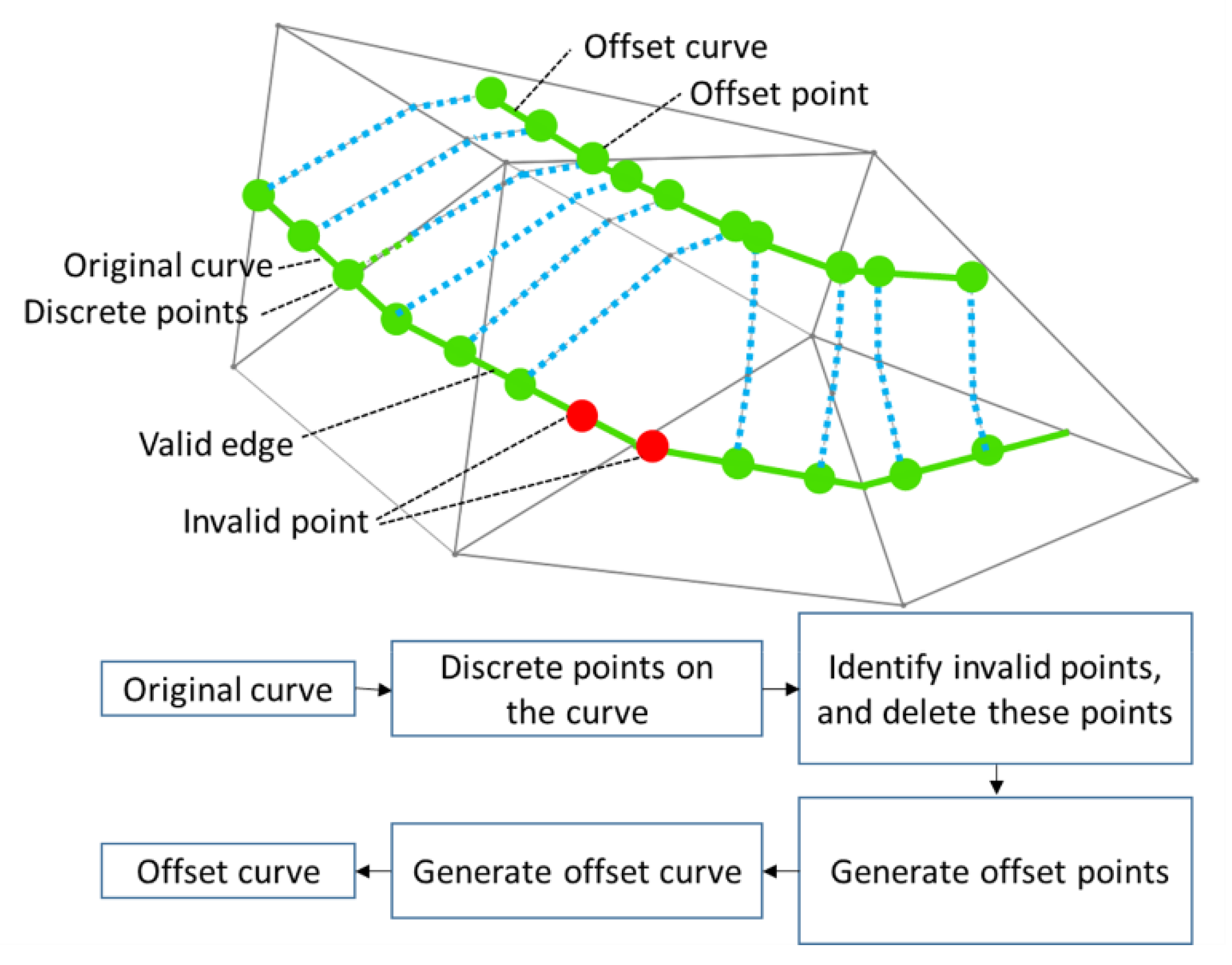
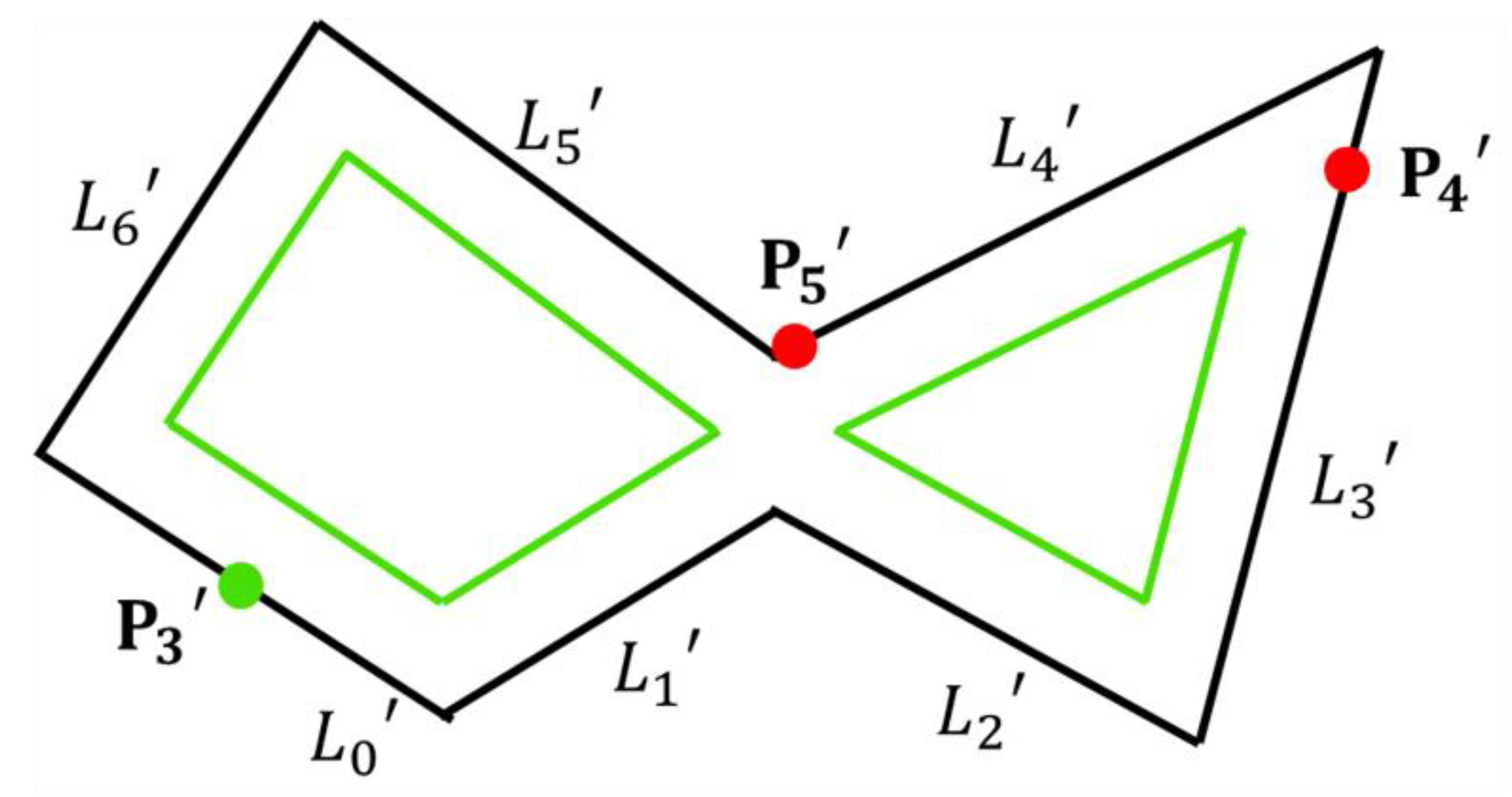
3.2.1. Outline of CODP

Figure 6 shows the algorithm flow of the CODP.
The first step is to generate discrete points on the original curve. The spacing value of the discrete points is set to one-tenth of the offset distance.
The second step is to judge and eliminate the invalid points on the original curve. A judgment method would be used here. The invalid points would be removed to avoid local self-intersection and global self-intersection.
The third step is to generate offset points according to the remaining points on the original curve.
The last step is to generate the offset curve with the offset points. A connection surface would be constructed to generate the connected lines.

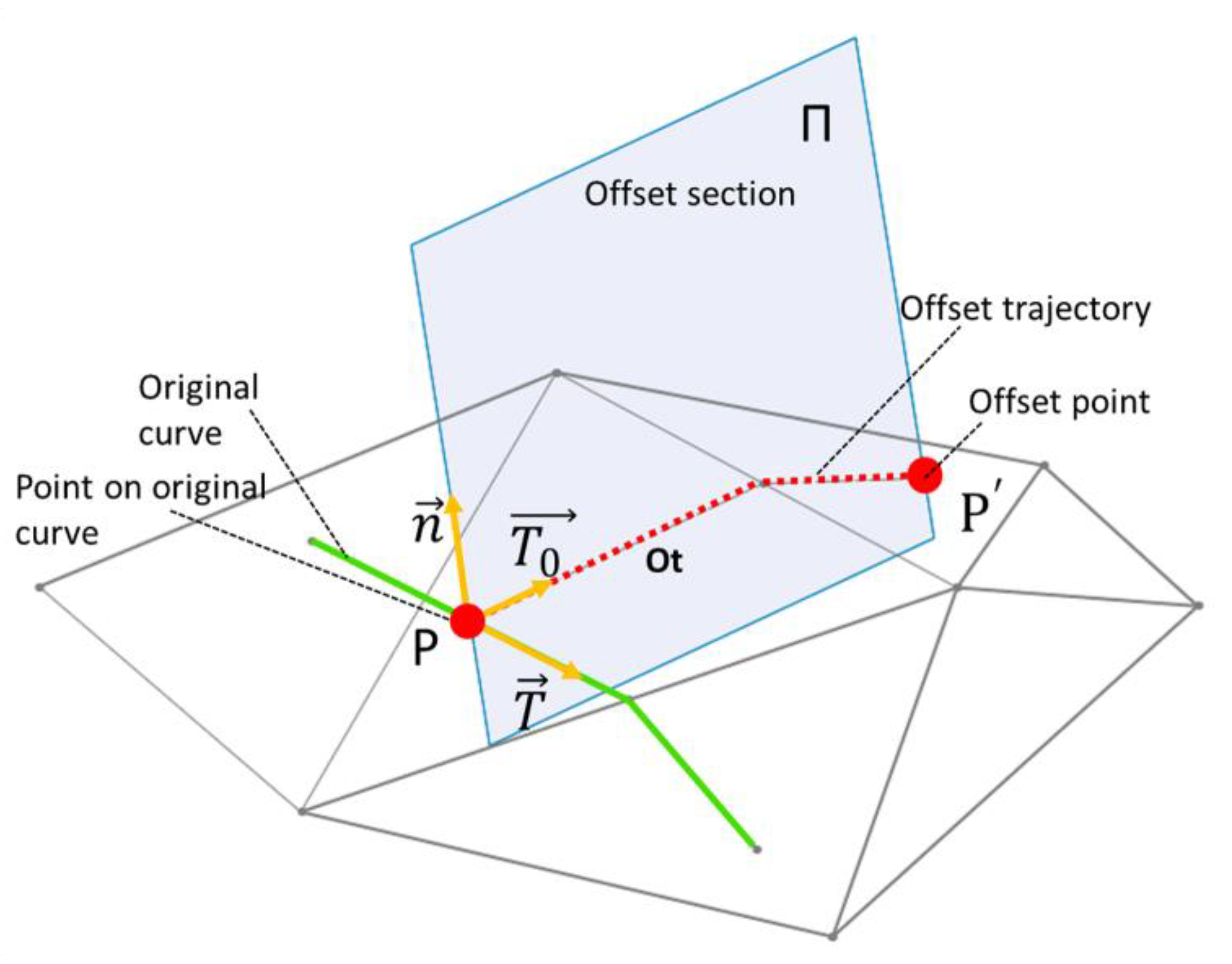
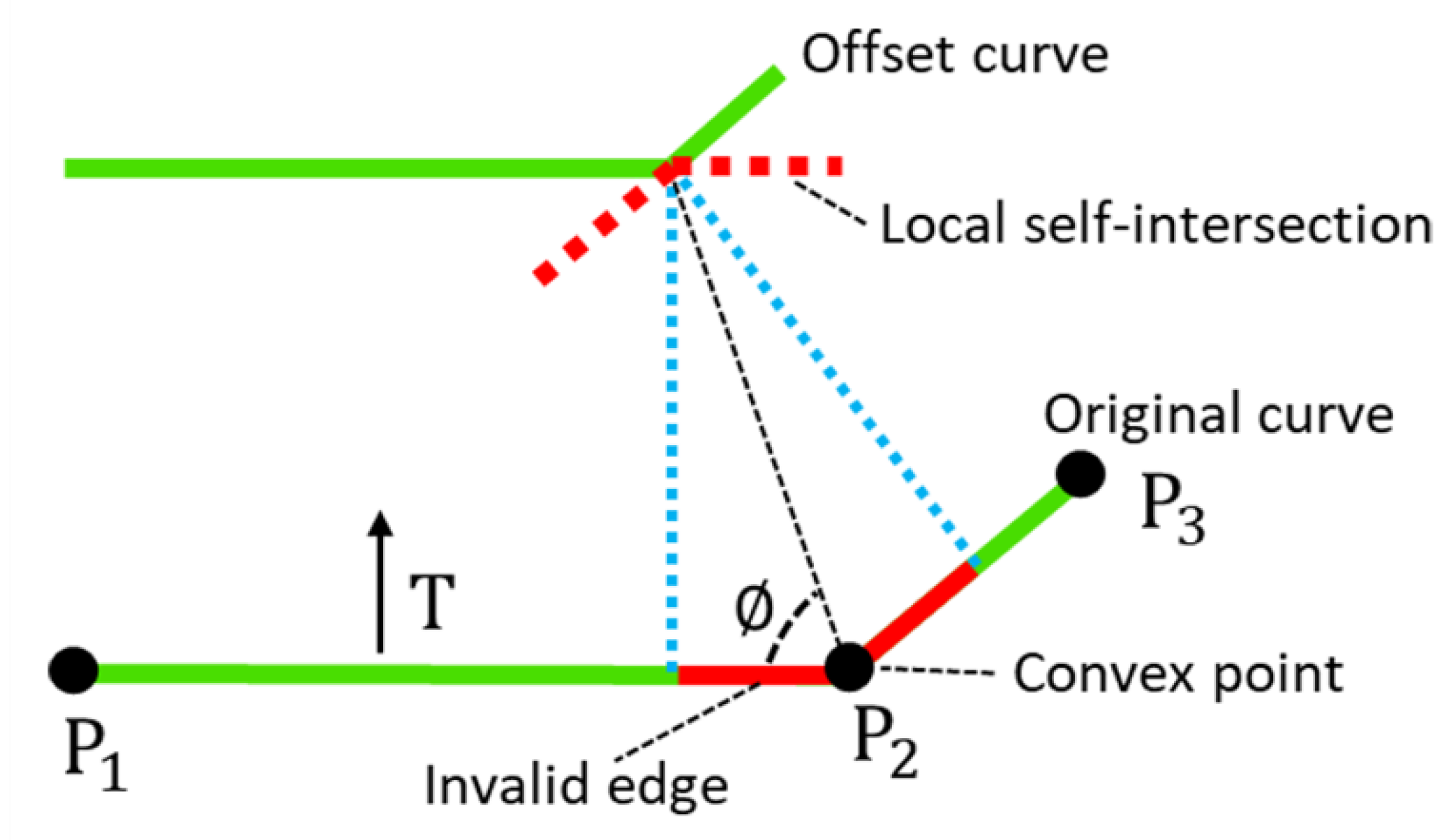
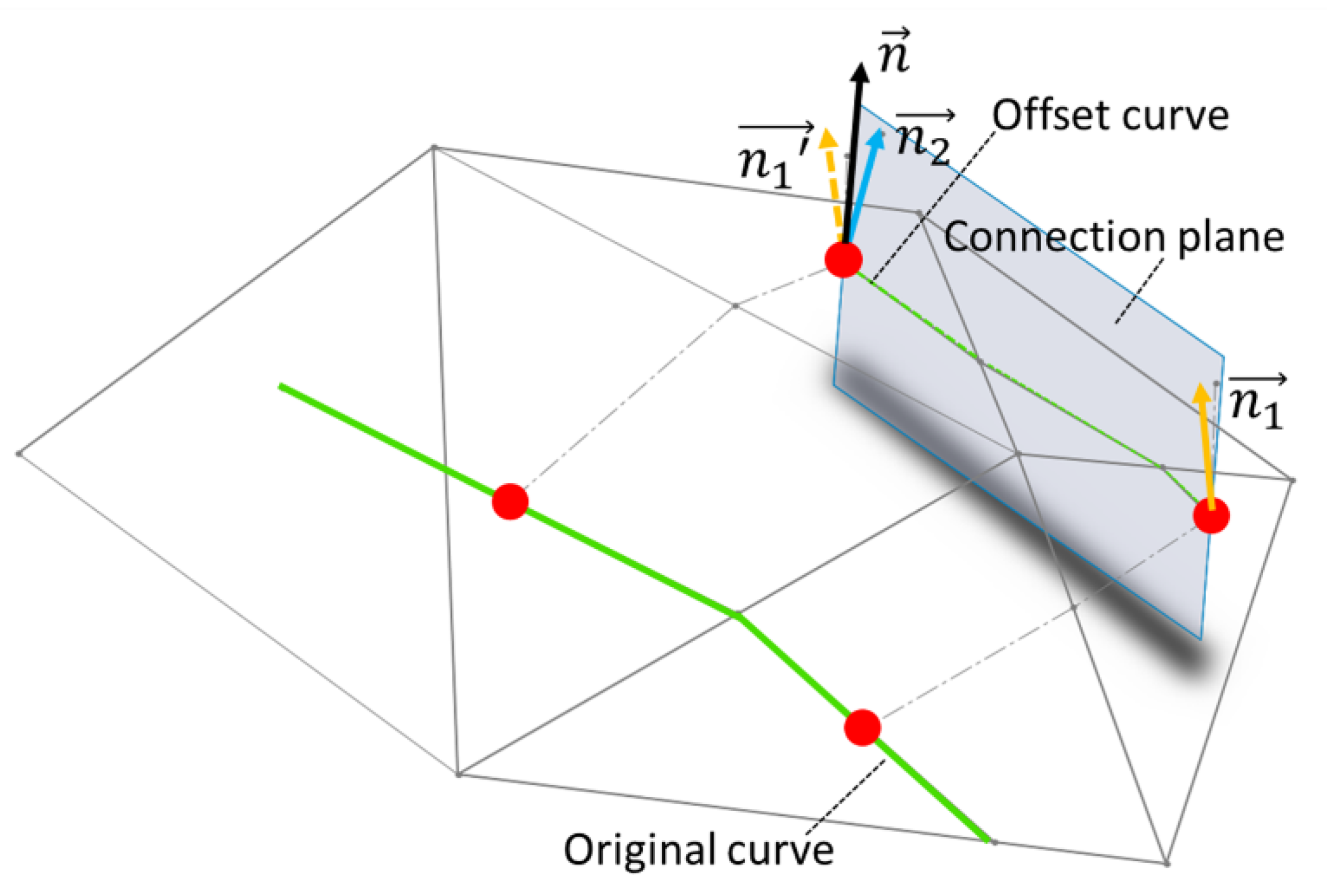
3.2.2. Details of CODP

(1) The calculation of offset points on a triangular mesh surface
Here are the main steps of the CODP. Figure 7 shows the schematic diagram of the offset point calculation on a triangular mesh surface. Point P is one of the discrete points on the original curve, n is the normal vector of the surface where P is located, T is the tangent vector of the curve where P is located, and T 0 is calculated by T and n ( T 0 = T × n ) and regarded as the geodesic vector of P to the original curve. The offset section Π is generated by n and T 0 . The offset trajectory Ot is generated by calculating the intersection polyline between the offset section and the triangular mesh surface. The offset point P’ is obtained on the offset trajectory, which has a distance of the offset value to P along Ot.
(2) Judgment of invalid points
Definition of Invalid Points. As shown in Figure 8, on the original curve, P 1 and P 3 are the two points on two sides of P 2 . A judgment plane can be created by the line P 1 P 2 and the normal direction of the triangular facet where the line P 1 P 2 is located. T is the offset direction of the line P 1 P 2 . If T and P 3 are located on the same side of the judgment plane, P 2 is defined as a convex point. According to the relevant research about curve offsetting, the line near the convex point will cause a local self-intersection, like the red segment shown in Figure 8, and it is defined as an invalid edge. Similarly, the edges which cause global self-intersection are also defined as invalid edges. In this paper, the discrete points are generated on the original curve, and the points on the invalid edge are called invalid points.
Judgment of Invalid Points. To judge the invalid points, we propose an offset region judgment method. The offset region is a close area surrounded by the original segment ( L 2 ), the two offset trajectory polylines of the two ends of the original segment, and the offset segment, as shown in Figure 9. The method is used to determine if there are intersections between the offset region of the segment on the original curve and the offset trajectories of the other discrete points. For example, Figure 9 shows the intersection between the offset region and the offset trajectory. P 1 and P 2 are the two discrete points. The offset trajectory of P 1 intersects with the offset region of L 2 , while P 2 does not.
For a discrete point, except for the line where the point is located, intersection judgments for all the other segments on the original curve are needed. As long as there is one segment whose offset region intersects with the offset trajectory of a discrete point on the original curve, the point is defined as an invalid point. All the discrete points on the original curve need to be judged point-by-point to determine whether they are invalid points or not. For example, as shown in Figure 10, taking three of the discrete points on the original curve as an example, the offset trajectory of P 3 does not intersect with the offset region of other segments, which is a valid point. However, the offset trajectory of P 4 intersects with the offset region of L 4 , so it is an invalid point. In addition, since P 5 would intersect with the opposite segment L 2 , it is also an invalid point.
The invalid points would not be taken into the offset calculation. Therefore, the method can effectively remove the local self-intersection and global self-intersection in the offset process.
(3) Generation of offset points and the offset curve
After the judgment of the invalid points, the invalid points are removed, and then the offset points are generated from the remaining discrete points. The details are shown in the above section, “The calculation of offset points on a triangular mesh surface.” Since the discrete points are ordered on the original curve, the offset points are also ordered and attached on the triangular mesh surface. In this step, the offset curve can be obtained by sequentially generating connected lines between adjacent offset points. Figure 11 shows the offset segment generation between two adjacent offset points. A connection plane can be established based on the two offset points and the vector n ( n = n 1 + n 2 ,   n 1 ,   n 2 , which are the normal vectors of the triangular facets where the offset points are located, and n lies in the connection plane). In addition, an intersection polyline could be obtained between the triangular mesh surface and the connection plane.
As shown in Figure 12, taking a high-heeled shoe model as an example, we set the starting layer height as 5 mm, the offset distance as 2 mm, and the distance between adjacent discrete points as 0.1 times the offset distance. The results show that the stability of the offset algorithm and the filling effect of the theoretical printing points are very good.

4. Color Printing Experiments and Comparisons

We made comparisons between the results of the OCPP and AFSM in [11] on a revolving surface and on a freeform surface, respectively. The filling rate (FR) was used to evaluate the filling effect and was defined as the ratio of the printing point area to the pattern area on the surface, which was calculated by Equation (1):
F R = d o t   n u m b e r × π × ( d a 2 ) 2 s u r f a c e   a r e a
Since the shape of a printing point is round, though they are closely arranged, there is still clearance among printing points. When the diameter of a printing point is very small, the clearance can be ignored. So, the theoretical filling rate (TFR) is proposed as a more appropriate evaluation. We assume that the shape of a printing point is a square, which ignores the influence of the clearance. The formula is:
T F R = d o t   n u m b e r × d a 2 s u r f a c e   a r e a

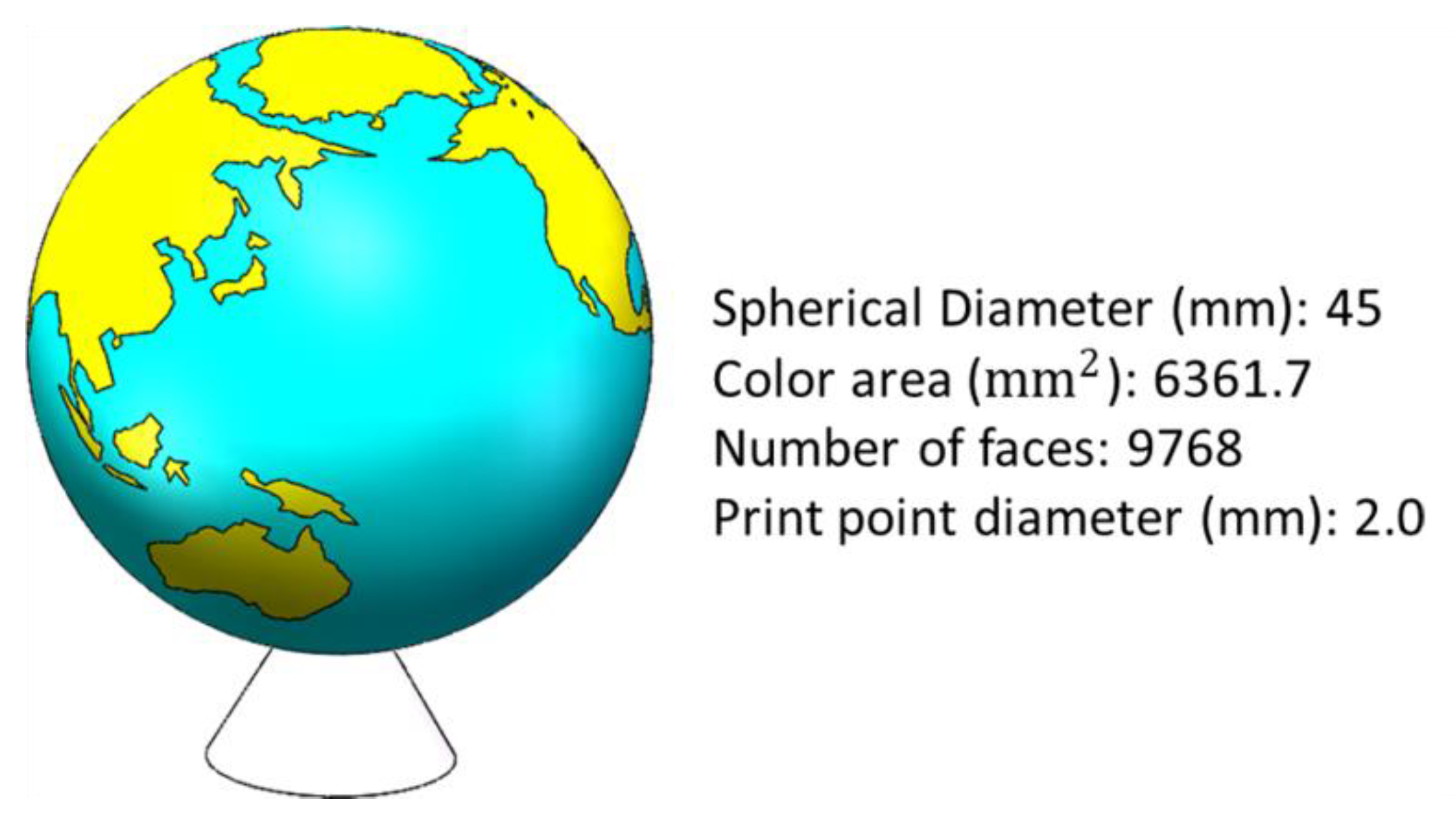
4.1. The Earth Model

The Earth model is used as a revolving surface for comparison. Figure 13 shows the parameters of the Earth model. The diameter of each printing point is 2 mm. The resolution can be defined as the area of one single printing point (π × 2 mm × 2 mm/4 = 3.14 mm2). The filling result is shown in Table 1, and the AFSM has a good filling effect and the TFR reaches 0.972. However, the AFSM also has a defect at the top of the Earth model. Since the inclination angle is infinitely close to 90° there, there would be a problem in that the next contour line cannot be generated, resulting in an unfilled area at the top. The OCPP method could avoid the problem of the AFSM, and the TFR of the OCPP has been further improved with a better filling effect. However, since the calculation of the OCPP is more complex than the AFSM, for patterns on a revolving surface, if there are no positions where inclination angles are very close to 90°, the AFSM would be preferred.

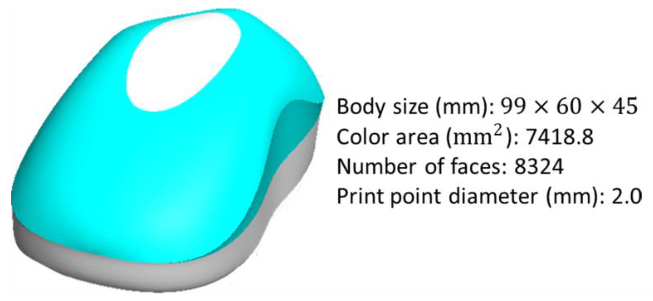
4.2. The Mouse Model

The mouse model is used as a freeform surface for comparison. The parameters of the mouse model are shown in Figure 14.
As shown in Table 2, on a freeform surface, the filling results show that the TFR of the AFSM is only 0.897 and the filling effect is not very ideal, while the TFR of the OCPP can reach 0.996 with a very good filling effect. Therefore, for patterns on freeform surfaces, the OCPP method is ideal to generate color printing points.
With both the Earth model and the mouse model, the TFRs under the OCPP method are both very close to 1, which means the filling results are good, and our OCPP method has good applicability to general models.

5. Conclusions

In order to promote the filling rate of color printing points, based on the previous work of our team and the research on curve offsetting, a path planning method based on the offset curve is put forward. From the experiments, especially for freeform surfaces, the TFR significantly increased, which illustrates the feasibility of the OCPP method. The three main achievements that have been made in our work are:
(1)
The five-axis single point color printing technology was put forward.
(2)
The path planning algorithm based on the offset curve was presented, including the algorithm process and details.
(3)
Comparisons between the two path planning methods (AFSM and OCPP) were made. The TFR was put forward to evaluate the filling effect. It turns out that for a freeform surface, the OCPP had a better filling result.

Author Contributions

Investigation, B.L. and S.L.; writing (original draft preparation), B.L.; visualization, B.L. and S.L.; project administration, H.S. and J.F. All authors have read and agreed to the published version of the manuscript.

Funding

This work was financially supported by the National Natural Science Foundation of China (No. 51975518), the Science Fund for Creative Research Groups of the National Natural Science Foundation of China (No. 51821093), Key Research and Development Plan of Zhejiang Province (No. 2018C01073), Ningbo Science and Technology Plan Project (2019B10072), and the Fundamental Research Funds for the Central Universities (No. 2019QNA4004). The founding sponsors had no role in the design of the study; in the collection, analysis, or interpretation of data; in the writing of the manuscript; or in the decision to publish the results.

Acknowledgments

Thanks for the partial technical support by Weijun Sun in our research group.

Conflicts of Interest

The authors declare no conflicts of interest.

References

  1. Pan, J.; Tonkay, G.L.; Quintero, A. Screen printing process design of experiments for fine line printing of thick film ceramic substrates. J. Electron. Manuf. 1999, 9, 203–213. [Google Scholar] [CrossRef]
  2. Hahne, P.; Hirth, E.; Reis, I.E.; Schwichtenberg, K.; Richtering, W.; Horn, F.M.; Eggenweiler, U. Progress in thick-film pad printing technique for solar cells. Sol. Energy Mater. Sol. Cells 2001, 65, 399–407. [Google Scholar] [CrossRef]
  3. Tian, J.; Mao, Y.; Shen, W. Ink transfer and refusal mechanisms in waterless offset printing. J. Adhes. Sci. Technol. 2009, 23, 281–296. [Google Scholar] [CrossRef]
  4. Sirringhaus, H.; Shimoda, T. Inkjet Printing of Functional Materials. MRS Bull. 2003, 28, 802–806. [Google Scholar] [CrossRef] [Green Version]
  5. Sachs, E.; Cima, M.; Cornie, J. Three-Dimensional Printing: Rapid Tooling and Prototypes Directly from a CAD Model. CIRP Ann. Manuf. Technol. 1990, 39, 201–204. [Google Scholar] [CrossRef]
  6. Edgar, J.; Tint, S. Additive Manufacturing Technologies: 3D Printing, Rapid Prototyping, and Direct Digital Manufacturing. Johnson Matthey Technol. Rev. 2015, 59, 193–198. [Google Scholar] [CrossRef]
  7. Jean-Pierre, G.; Saïd, Z.; Gabriel, R.T. A novel 5-axis robot for printing high resolution pictures from media on 3D wide surfaces. In Proceedings of the Proceedings of the IEEE International Conference on Industrial Technology, Gippsland, VIC, Australia, 10–13 February 2009; pp. 1–6. [Google Scholar]
  8. Zhang, Y.; Yin, C.; Zheng, C.; Zhou, K. Computational hydrographic printing. ACM T Graph. 2015, 34, 131–132. [Google Scholar] [CrossRef]
  9. Zhang, Y.; Tong, Y.; Zhou, K. Coloring 3d printed surfaces by thermoforming. IEEE Trans. Vis. Comput. Graph. 2017, 23, 1924–1935. [Google Scholar] [CrossRef] [PubMed]
  10. Solid Terrain Modeling. Available online: http://www.solidterrainmodeling.com/ (accessed on 31 January 2020).
  11. Trek Bicycle, soluciones reales, para el ciclismo, con la ayuda, de la Objet®500 and Connex3TM de Stratasys. Autocad Mag. 2015, 3, 32–35.
  12. ORD Solutions. Available online: https://www.ordsolutions.com/ (accessed on 31 January 2020).
  13. James, C. Reprap Colour Mixing Project; University of Bath: Bath, UK, 2012. [Google Scholar]
  14. Spectrom 3D Divulges Plans for Individual Voxel Coloring within FFF 3D Printing Process. Available online: https://3dprint.com/36211/spectrom-3d/ (accessed on 31 January 2020).
  15. Shen, H.; Liu, S.; Wu, S.; Zhang, L.; Sha, J. Free-form surface-oriented five-axis single-point color printing technology. Proc. Inst. Mech. Eng. Part I J. Syst. Control Eng. 2019, 233, 1159–1171. [Google Scholar] [CrossRef]
  16. Pham, B. Offset curves and surfaces: A brief survey. Comput. Des. 1992, 24, 223–229. [Google Scholar] [CrossRef]
  17. Maekawa, T. Overview of offset curves and surfaces. CAD Comput. Aided Des. 1999, 31, 165–173. [Google Scholar] [CrossRef]
  18. Piegl, L.A.; Tiller, W. Computing offsets of NURBS curves and surfaces. CAD Comput. Aided Des. 1999, 31, 147–156. [Google Scholar] [CrossRef]
  19. Choi, B.K.; Park, S.C. A pair-wise offset algorithm for 2D point-sequence curve. CAD Comput. Aided Des. 1999, 31, 735–745. [Google Scholar] [CrossRef]
  20. Rickk, C.; Gavin, B. The Annotated VRML 2.0 Reference Manual; Addison-Wesley Longman Ltd.: London, UK, 1997. [Google Scholar]
  21. Holla, V.D.; Shastry, K.G.; Prakash, B.G. Offset of curves on tessellated surfaces. CAD Comput. Aided Des. 2003, 35, 1099–1108. [Google Scholar] [CrossRef]
Figure 1. Single-point color nozzle.
Applsci 10 01716 g001
Figure 2. Surface patterns are formed by a series of printing points.
Applsci 10 01716 g002
Figure 3. Five degrees of freedom (DOF) printing.
Applsci 10 01716 g003
Figure 4. Normal direction printing mode. ① a posture when printing Letter Z, ② a posture when printing Letter J, ③ a posture when printing Letter U.
Applsci 10 01716 g004
Figure 5. Process of the offset curve path planning (OCPP). VRML: virtual reality modeling language.
Applsci 10 01716 g005
Figure 6. Algorithm flow of the curve offsetting based on a discrete point (CODP).
Applsci 10 01716 g006
Figure 7. Offset point generation on a triangular mesh.
Applsci 10 01716 g007
Figure 8. Convex point and local self-intersection.
Applsci 10 01716 g008
Figure 9. Intersection judgment between the offset region and the offset trajectories of the other discrete points.
Applsci 10 01716 g009
Figure 10. Judgment of the invalid points.
Applsci 10 01716 g010
Figure 11. Offset curve generation between two adjacent offset points.
Applsci 10 01716 g011
Figure 12. (a) Virtual reality modeling language (VRML) model of a high-heeled shoe; (b) offset curves generated by the OCPP; (c) theoretical filling result.
Applsci 10 01716 g012
Figure 13. The Earth model.
Applsci 10 01716 g013
Figure 14. The mouse model.
Applsci 10 01716 g014
Table 1. Comparison between the adaptive filling algorithm based on the section method (AFSM) and OCPP for a revolving surface.
AFSMOCPP
Simulation Applsci 10 01716 i001 Applsci 10 01716 i002
Experiment Applsci 10 01716 i003 Applsci 10 01716 i004
FR0.7630.781
TFR0.9720.994
Table 2. Comparison between the AFSM and OCPP for a freeform surface.
AFSMOCPP
Simulation Applsci 10 01716 i005 Applsci 10 01716 i006
Experiment Applsci 10 01716 i007 Applsci 10 01716 i008
FR0.7050.782
TFR0.8970.996

