Article

Efficient Hogel-Based Hologram Synthesis Method for Holographic Stereogram Printing

1
School of Information and Communication Engineering, Chungbuk National University, Cheongju 28644, Korea
2
Department of Electronic Engineering, Wonkwang University, Iksan 54538, Korea
3
Department of Electronics Engineering, Incheon National University, Incheon 22012, Korea
*
Author to whom correspondence should be addressed.
Appl. Sci. 2020, 10(22), 8088; https://doi.org/10.3390/app10228088
Submission received: 4 September 2020 / Revised: 13 October 2020 / Accepted: 11 November 2020 / Published: 15 November 2020
(This article belongs to the Special Issue Practical Computer-Generated Hologram for 3D Display)

Abstract

:
With the development of the holographic printer, printing synthetic hologram requires smaller holographic element (hogel) size to improve spatial resolution of the reconstruction. On the contrary, a larger hogel size affords higher angular resolution, but it leads to a lower lateral resolution and there exists a trade-off problem. In this paper, a hologram synthesis method based on three-dimensional (3D) rendering of computer-generated holographic stereogram (HS) is proposed to limit the spatial-angular trade-off problem. The perspectives of the 3D scene are captured by re-centering the camera method and transformed into parallax-related images by a proposed pixel re-arrangement algorithm for holographic printing. Unlike the conventional approaches, the proposed algorithm not only improves the angular resolution of the reconstruction while maintaining the hogel size fixed, but also keeps the spatial resolution without degradation. The effectiveness of the proposed method is verified by numerical simulation and an optical experiment.

Graphical Abstract

1. Introduction

Holography is a two-step technique that records and reconstructs the intensity and phase information of a wavefront scattered from a three-dimensional (3D) object [1,2,3]. Recently, many researchers have been paying attention to the holographic printers as a technique to visualize the holographic contents of a 3D object. The 3D virtual models can be easily implemented by a holographic printer, which can be divided into two main types: wavefront printer and a holographic stereogram (HS) printer. The wavefront printer records an arbitrary object field while retaining full control of both the amplitude and phase distributions of the 3D object as does the traditional analogue hologram [4,5,6,7,8]. Among the various holographic representation approaches, the holographic stereogram (HS) is the most common incoherent reconstruction technique. In HS, the angular information is stored as a holographic pixel or hogel and a sub-hologram is commonly generated from many perspectives of a 3D scene. A hogel is the smallest holographic element of a light field hologram and an array of these elements forms the entire image. Each hogel image diffracts the light as a plane wave where the intensity can change depending on the viewing angle. The advantage of the HS printer is that there is no complex diffraction calculation compared with the wavefront printer, which requires complex field extraction from a 3D object. Digital content generation is relatively simple for the HS printer. The HS printer records a set of two-dimensional (2D) parallax-related images created from an array of perspective projections of a 3D scene [9,10,11,12,13,14]. For the hogel-based approaches, hogel images are usually re-arranged by a conventional pixel re-arrangement algorithm, which was proposed by Bjelkhagen and Brotherton [15]. One drawback of this pixel re-arrangement technique is that there exists a trade-off problem between spatial-angular resolution of the reconstructed HS. Therefore, it needs a high memory usage and computation time to acquire a large number of perspectives.
Various approaches have been proposed to realize the holographic stereogram printing technology with or without a hogel re-arrangement technique. A hogel image for HS can be created from phase-modulated or phase kinoforms using e-beam lithography [16,17]. Refreshable HSs can be recorded rapidly and continuously without an X-Y translation stage and replaced it with an uninterrupted translation belt holding holographic lenses [18]. Non-hogel-based calculations, which generate HSs with continuous wavefronts for each object point has been presented recently [19]. Unlike conventional approaches, a non-hogel based method synthesizes holograms without hogel configuration, generating a converging parabolic wave for each object point with a continuous wavefront compared with conventional hogel-based approaches. A new method based on effective perspective image segmentation and mosaicking (EPISM) for single-step exposure was proposed [20]. The hogels are exposed using the synthetic effective images in sequence by mosaicking under the optimized modelling parameters. Recently, authors in Reference [21] have reviewed the development and research status of the synthetic holographic stereogram printing technique. Authors in Reference [22] show that the light-field based CGH techniques have advantages to explore near-eye light field displays for presenting high-definition 3D scenes with continuous depth and support of view-dependent occlusion. By combining light-field rendering and a Fresnel diffraction calculation, the aliasing in both over-sampling and under-sampling can be solved.
In this paper, we present an efficient hologram synthesis method based on 3D rendering of computer-generated HSs by a pixel re-arrangement algorithm to limit the trade-off problem between spatial-angular resolution of the reconstruction. This novel method improves the angular resolution of HS without increasing the hogel size, while keeping the spatial resolution without degradation. First, the perspectives of a 3D scene are acquired by a re-centering camera model, which is explained in Section 2.1. Second, a proposed pixel re-arrangement algorithm is applied to rearrange the acquired perspective images into higher resolution hogel images. This process reduces the number of rendered perspectives required in the recording of a full-parallax HS. The hogel images, which are generated by a proposed pixel re-arrangement technique, exhibit much higher resolution than conventionally rearranged hogels (Section 2.2). Finally, the transformed hogels are served as an input dataset for recording on holographic material based on general operation principles of the holographic printer system, which is described in Section 3.

2. Method

2.1. Acquisition of Perspective Images

A holographic stereogram is synthesized conventionally based on three procedures: acquisition of perspectives, the transformation from perspective images to parallax-related images, and hogel printing. Figure 1 shows a schematic procedure of hogel-based holographic stereogram synthetization approach. The perspective projections of a 3D scene are usually acquired by an array of virtual cameras based on a re-centering camera model in Blender software. In recording of a full-parallax HS, we assume that (M × N) view projections of resolution (m × n) are captured along the horizontal and vertical axes, respectively. The perspectives are numbered (M × N) in the camera plane such that the upper-left projection is (1, 1) and the lower-right projection is (M, N).
The array of these captured perspectives is stored in image matrix P as:
P = ( P 1 , 1 P 1 , 2 P 1 , N P 2 , 1 P 2 , 2 P 2 , N P M , 1 P M , 2 P M , N )
For each hogel, the object field for HS is a superposition of rectangularly propagated plane waves with amplitudes defined by the corresponding discrete light field samples. For the simplicity, the object field at the hologram plane is defined in one dimensional as:
O H S ( x ) = h r e c t ( x h Δ x Δ x ) × r P M , N exp ( j 2 π f x h r x )
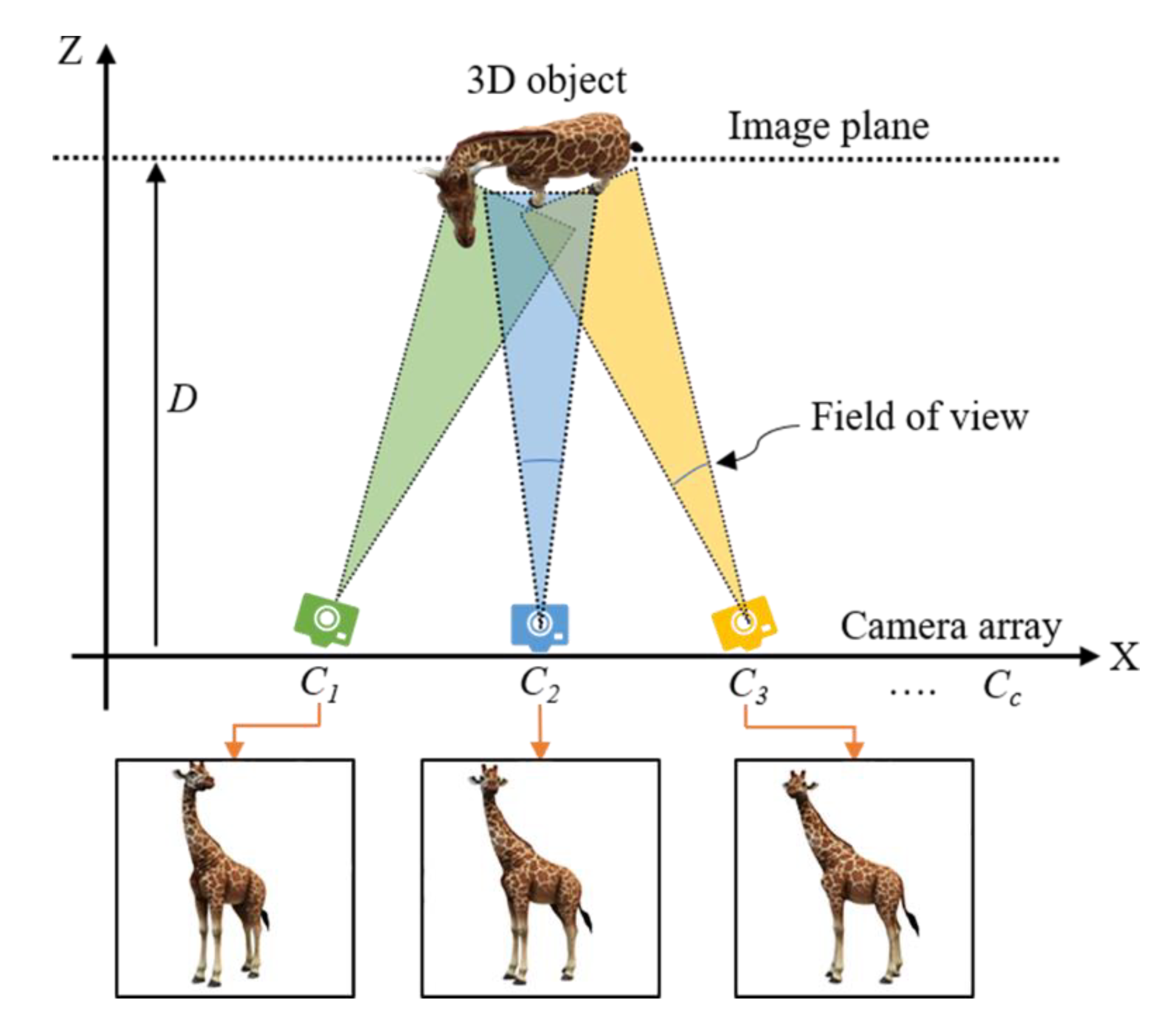
where f x h r is the spatial frequency of hogel h and ray r on the x axis and Δ x is the hologram plane sampling distance. The inner sum in Equation (2) is the spatial pattern to be written in the corresponding hogel and can be obtained by inverse Fourier transformation of parallax-related images. Figure 2 shows the acquisition geometry of the perspectives obtained by the re-centering camera model.
The perpendicular re-centering image plane lies at a distance D from the camera array Cc where the perspectives are captured at the centre of projection for each camera that crosses the centre of the re-centering plane. The advantage of re-centering camera model is that, less of the field of view is wasted when capturing rays emitted by the object. One limitation of the holographic stereogram is its poor imaging resolution for 3D scenes with a big depth range or located far from the hologram plane. When objects located far from the camera plane may be under-sampled, resulting in a blurred reconstruction. However, these images will be algorithmically distorted at each image taken at a different angle. The virtual cameras in the re-centering camera method were calibrated such that the its field of view (FOV) was equal to the FOV produced by the imaging lens system. Therefore, we place the virtual cameras close to the 3D object and rendered directional view images to avoid this problem. Given the properties of the geometric model, each pixel at the image plane corresponds to the same pixel in the captured image. The camera C1 captures the leftmost top position, and the camera Cc captures the rightmost bottom position (Figure 2).

2.2. Hogel Generation and Enhancement of Angular Resolution by the Pixel Re-Arrangement Algorithm

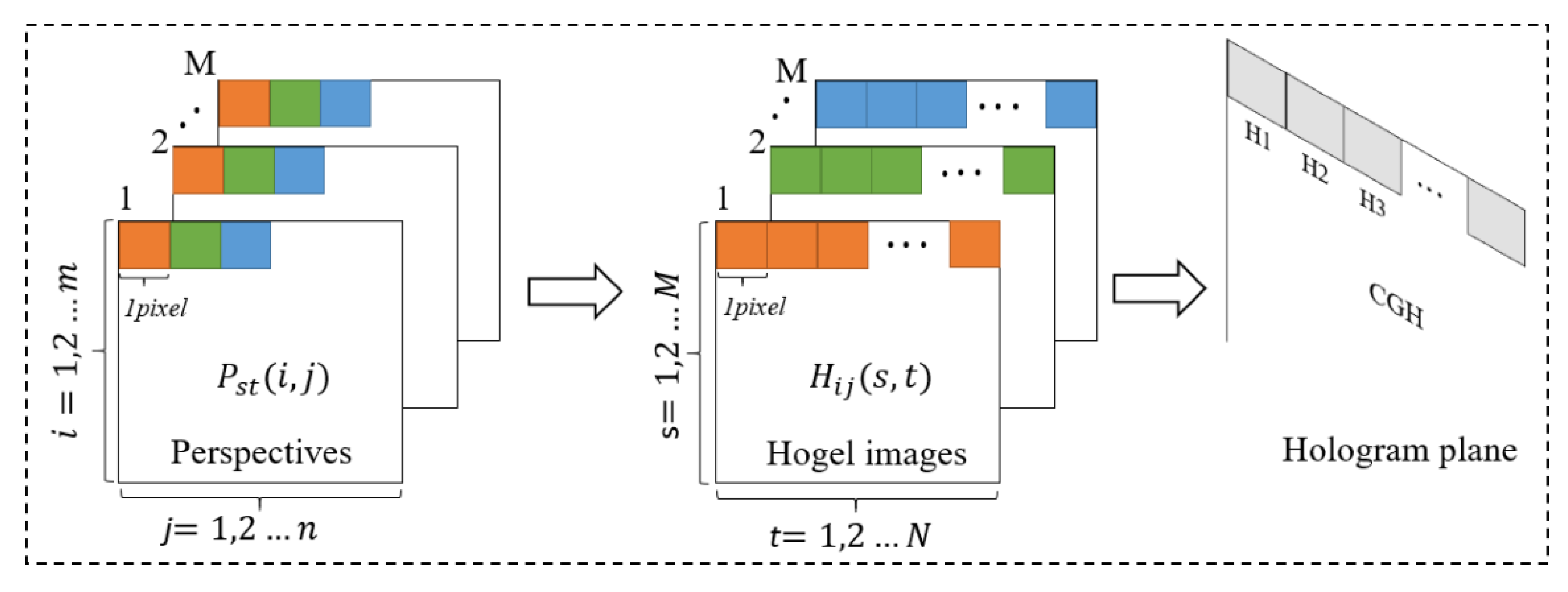
In order to perform the reconstruction of the holographic stereogram without a distortion, the perspectives must be re-arranged to form parallax-related images corresponding to different volume holograms in the hologram plane. The conventional pixel re-arrangement technique creates a sequence of hogels reflecting the angular intensity distribution of the 3D object, which is related to the smooth motion-parallax information available at the viewer’s position. The holographic stereogram synthesizes a small volume hologram of the re-arranged hogels. When the hologram is illuminated, each hogel is simultaneously reconstructed. The changes in both intensity and parallax are made by reference to the hogel angular intensity distribution. The pixel re-arrangement technique is employed to generate the array of hogel images Hij from a sequence of (M × N) perspectives captured in the horizontal and vertical directions. All pixels at the same perspective location are extracted in the horizontal and vertical directions to form a new matrix Hij composed using the pixels of all perspectives.
H i j ( s , t ) = P s t ( i , j ) ,   s = 1 M ; t = 1 N ; i = 1 m ; j = 1 n ;
In Equation (3), each perspective in image matrix P has (m × n) pixels and their number is given by M × N. On the contrary, the resolution of re-arranged hogel image is defined by M × N, and the number of images is m × n, according to Equation (3). This hogel-making process shows that the hogel image resolution is defined by the number of perspectives. Thus, the resolution of the hogel image is limited by the number of acquired perspectives subjected to a conventional pixel re-arrangement algorithm. The angular resolution of the reconstruction is determined by the number of hologram sampling points in each hogel. To re-arrange a higher resolution hogel, many perspectives are required to capture, according to Equation (3). Figure 3 presents the transformation of the perspectives to the parallax-related images by the conventional pixel re-arrangement technique based on Equation (3).
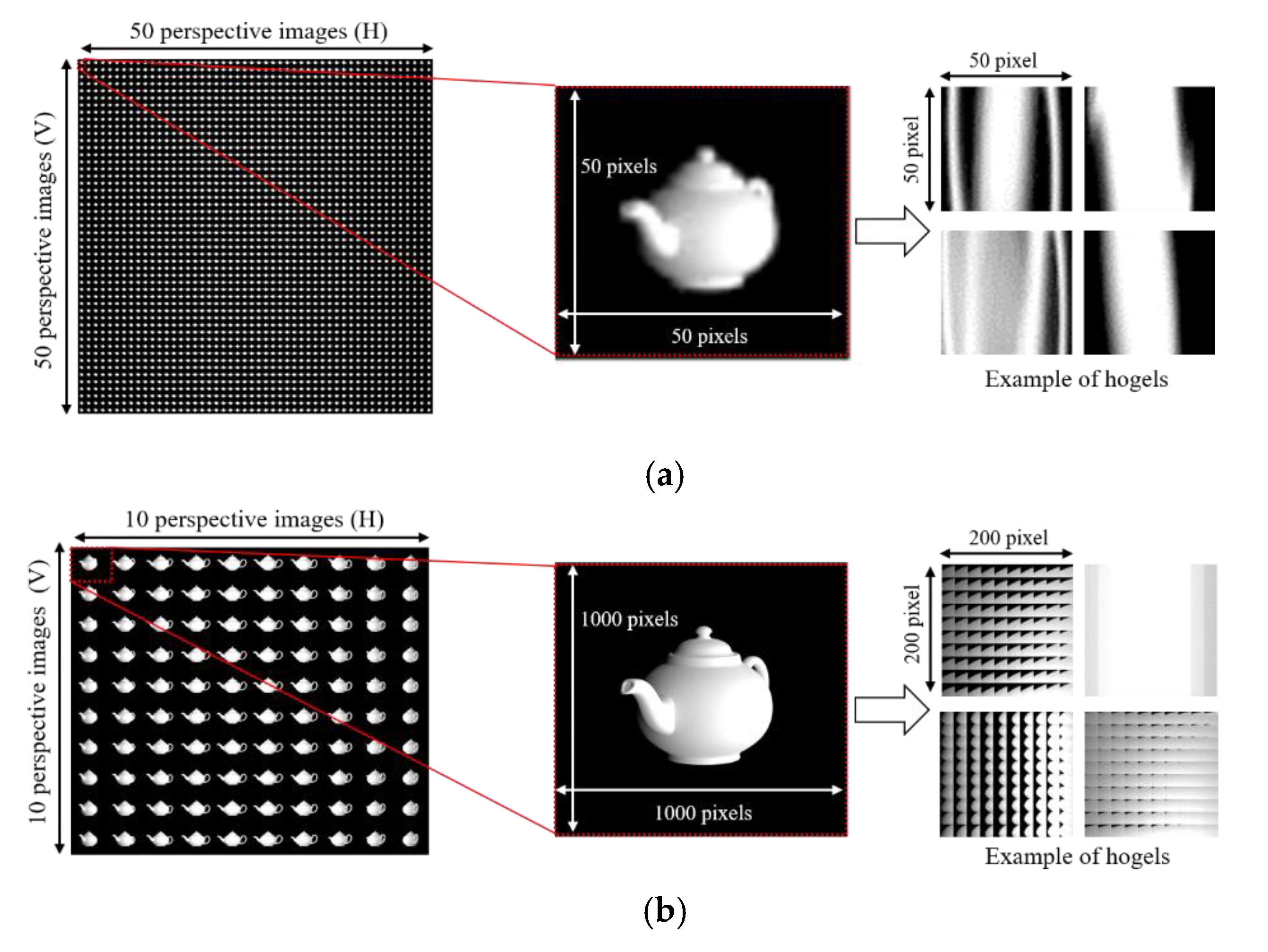
One drawback of the conventional hogel re-arrangement algorithm in Figure 3 is that a holographic stereogram improves angular resolution at the cost of spatial resolution as the hogel size increases. One important question for HS algorithms is how to choose the hogel size. A larger hogel size increases angular resolution and a smaller hogel size increases spatial resolution. When the hogel re-arrangement algorithm in Equation (3) is applied, there exists a trade-off problem between these resolutions. Therefore, it does not require a high memory usage and computation time to acquire a large number of perspectives at lower resolution because of the hogel re-arrangement process. In the proposed method, fewer perspective images with higher resolution are captured by re-centering the camera model (Figure 2) and then further processed to generate a plane wave moving in a certain direction. This wave is diffracted by hogel (i, j) onto the HS plane. The pixel (i, j) of each hogel image is diffracted by the hogel (m, n), corresponding to different locations in the HS. Then, a novel pixel re-arrangement algorithm is proposed to rearrange the higher resolution hogels from a reduced number of perspectives with high resolution compared to the conventional method. Instead of capturing many perspectives with lower resolution, fewer perspectives are pre-defined and captured with higher resolution. Based on fewer captured perspective images, the pixel re-arrangement algorithm in Equation (3) is modified into Equation (4) to satisfy the condition of the same number of hogels, which are re-arranged by the conventional method. Then, rather than extracting a single pixel from each perspective as shown in Figure 3, our algorithm extracts 20 pixels (the number of extraction factor can vary by the number of hogels to be recorded) from a reduced number of perspectives. This pixel-to-pixel distribution is defined as shown in Equation (4).
H u / 20 , v / 20 ( 20 × U , 20 × V ) = P U V ( u , v ) , U = 1 K ; V = 1 L ; u = 1 k ; v = 1 l ;
where U, V denotes the horizontal and vertical camera position with K × L captured images and u, v denotes the horizontal and vertical pixel position for each perspective with k × l image resolution. This process increases the re-arranged hogel resolution without any need for interpolation or pixel resizing, unlike the conventional method. It also improves the angular resolution of the reconstruction while retaining the hogel spatial resolution. This process is presented in Figure 4.
In this case, the hogel resolution is four times greater than that of a conventional re-arrangement. No pixel resizing, or interpolation, is required to match the resolution of the micro display. Thus, the total number of perspectives is reduced 25 times, and the proposed method avoids spatial resolution loss because of not applying a pixel re-sizing technique. The angular resolution of the reproduced light can be determined by the diffraction limit of the size of hogel and given by the following equation.
Δ θ ρ = Δ λ ρ
where ρ denotes the size of the elemental hologram and λ is the wavelength of the reconstructed light. To evaluate the angular resolution of diffracted light of HS for both methods, we obtain a different size of elemental holograms based re-arranged hogels by both methods. The size of the elemental hologram is 0.32 × 0.32 mm for the conventionally re-arranged hogel, whereas the size of the elemental hologram is 1.28 × 1.28 mm by the proposed approach based on a 6.4-um pixel pitch of the SLM display. Calculated results for angular resolution in Equation (5) were 1.66 and 4.15 degrees for the conventional and proposed method, respectively, when the wavelength λ is monochromatic light of 532 nm. As a result, the angular resolution was observed to be increased since the hogel size is raised by the proposed pixel re-arrangement algorithm. One holopixel on SLM corresponds to 4.66-degree angular resolutions. However, the number of perspectives is reduced by the proposed algorithm. It increases computation time for rendering and for a further hogel generation process, as shown in Table 1. This is one of the side effects on reducing perspective images and another effect exists on motion parallax information. Even fewer perspective images are captured within the same field of view (FOV) in the horizontal and vertical directions, respectively. The angular step of the virtual camera is increased in both directions, and the parallax changes rapidly within angular intensity distribution, which is not smooth when the observer’s eye moves hogel to hogel. Another drawback of the proposed method is that it leads to a deviation error in the reconstruction due to the proposed pixel re-arrangement algorithm. It is hard to correct this error and it is the physical nature of the method. Instead, hogels need to be captured in a direct way. When parallax-related images are generated in the hologram plane, each hogel is converted into a small volume hologram recorded on a holographic plate by our developed holographic printer. Holograms can be synthesised for the HS plane sampled from phase holograms by using phase-modulated (“phase-only”) SLM. Volume hologram of each hogel image is displayed on SLM sequentially and recorded on the holographic plate.

3. Results

3.1. Numerical Simulation

The proposed method was verified via numerical simulation. The perspectives of a virtual 3D scene were rendered using the re-centering camera model. Computer-graphic rendering process was performed on a Windows 10 64-bit PC with 8 GB of RAM, a 3.2 GHz Intel (R) i5-4570 CPU, and an NVIDIA GT 630 graphics card. Figure 5 shows the 3D scenes used in the experiment and its synthesized holograms from re-arranged hogels. Directional data for the synthetic 3D scenes were acquired at different viewing angles within a field of view of 30° as shown in Figure 5a,b. The distance between the object and hologram plane was 400 mm in each simulation and the depth between the two objects “Teapot and sphere” was 40 mm. A sub-hologram is commonly generated from many perspectives of a 3D scene, which are processed to form parallax-related images. This is defined by the H matrix as shown in Figure 3 and Figure 4. The parallax-related images contain directional information on the hologram plane, which can be observed as a spectral representation of the hologram (thus, a collection of spatial frequency components). In full-parallax HS, all hogels are mutually independent and further encoded as phase holograms, as shown in Figure 5.
Figure 6 shows the rendered perspective images with higher resolution in the proposed method compared with the captured perspective images at a lower resolution by the conventional method. In both cases, indexes of captured images and the resolution of a corresponding hogel is shown in numerical value and it was assumed that the hologram plane was synthesised from 50 × 50 hogels for both methods. Figure 6a presents 2500 perspectives (in terms of a numerical substitution of indexes and values) captured for the conventional method and example of re-arranged hogels. Figure 6b shows fewer perspectives at higher resolution for the proposed method. For hogels with a resolution of 200 × 200 pixels as shown in Figure 6b, larger hogels improve the angular resolution of an HS, and the accuracy of orienting the plane waves created locally within a hogel. It is confirmed by measurement results from Equation (5).
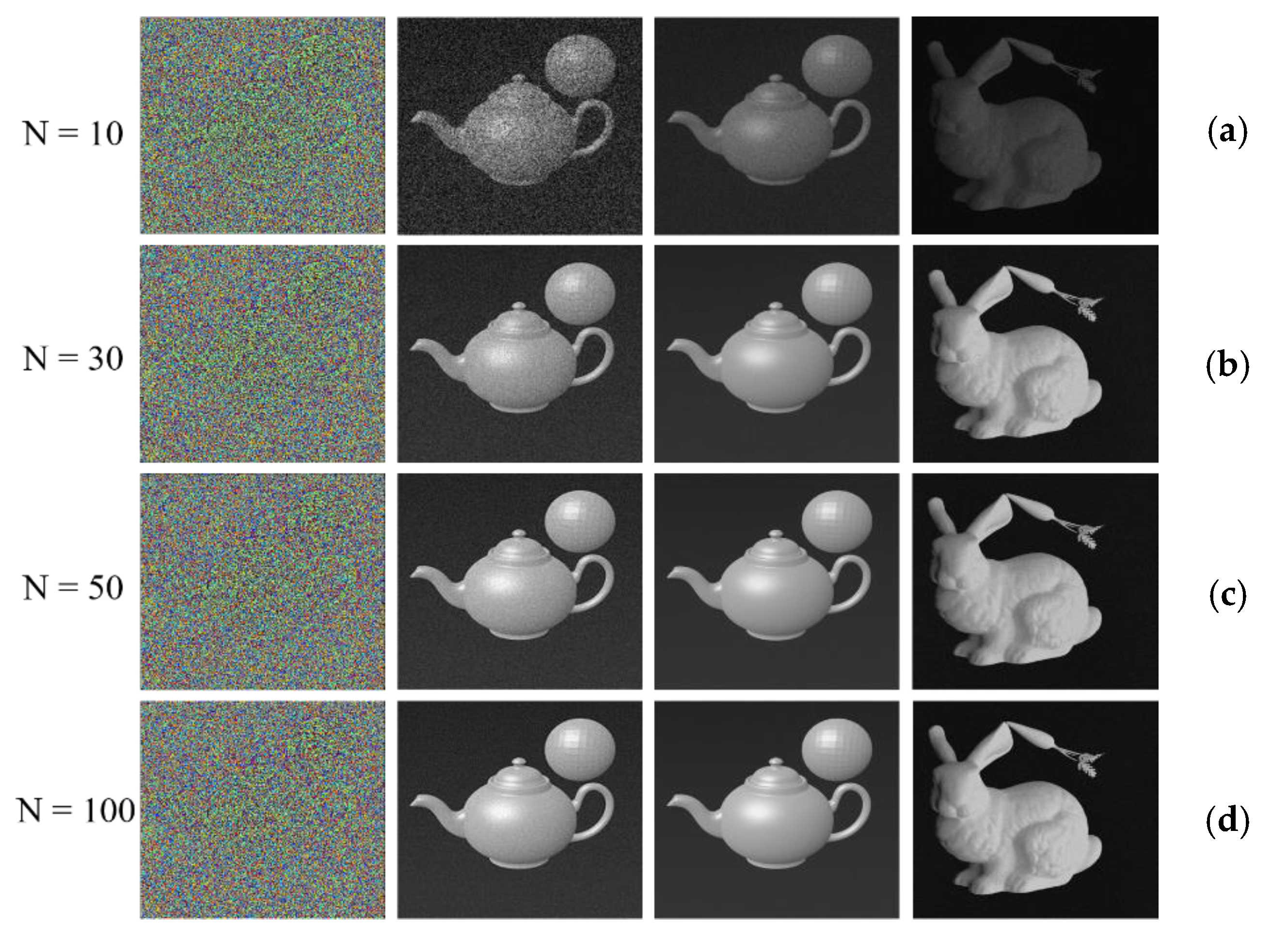
The conventional pixel re-arrangement technique re-arranges hogel with 50 × 50 pixels, according to Equation (3), and this process makes perspective image blurring at lower resolution, as shown in Figure 6a. On the contrary, the proposed method captures 100 perspectives based on a 10 × 10 camera array. Each view featured 1000 × 1000-pixel higher resolution, as shown in Figure 6b. In the proposed method, the size of each hogel is increased from 50 × 50 pixels to 200 × 200 pixels based on a proposed pixel re-arrangement algorithm. This process allows us to maintain the spatial resolution while benefiting from greater angular resolution from the larger hogel size compared to conventional re-arranged hogels. Figure 7 compares the numerical reconstructions of the two synthetic 3D scenes for the conventional and proposed method. The holograms were reconstructed at the distance of 400 mm for a 2 mm-diameter pupil. The holographic spatial sampling size was 129 µm. The sampling requirement for the human visual system was adopted and the perceived resolution was lowered. Thus, the hologram plane spatial sampling rate must not exceed this value if the perceived resolution is to be maximised. All hogels are encoded as phase holograms for holographic stereogram printing. The phase hologram for each hogel was calculated using the iterative Fourier transform algorithm (IFTA) after obtaining an array of parallax-related images using a phase-only spatial light modulator (SLM). Figure 7a shows the phase distribution at each iteration number of the IFTA.
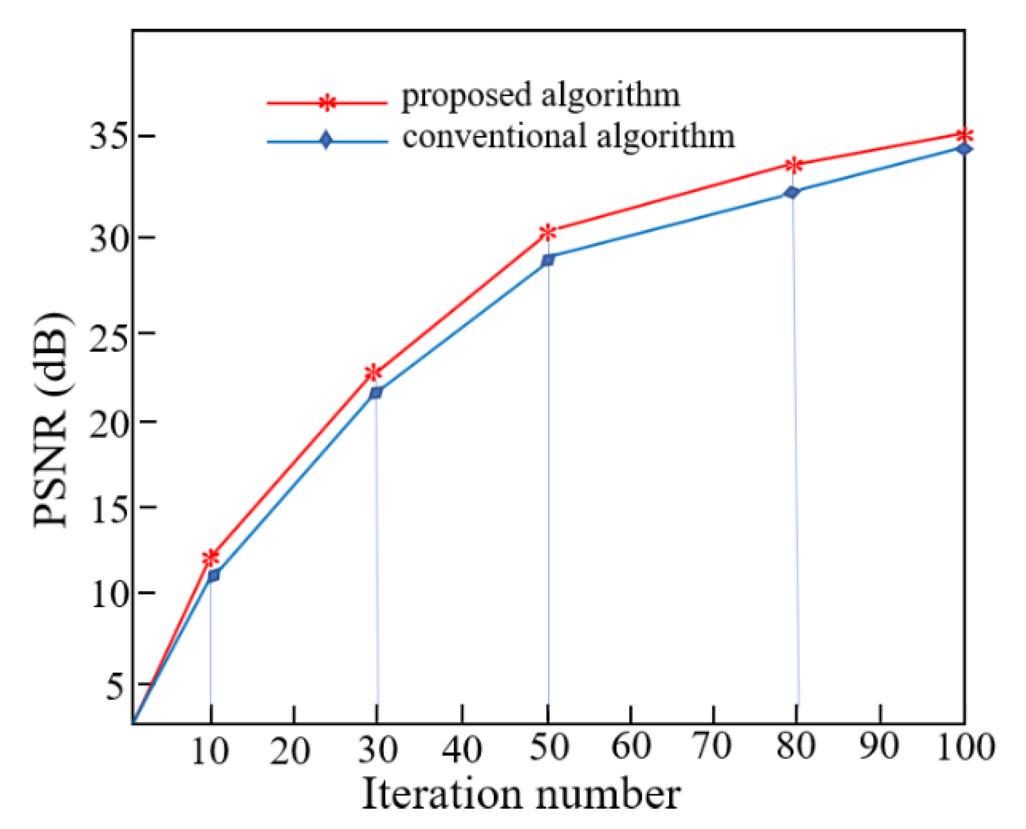
The holograms synthesised from light field data using the conventional and proposed method were reconstructed using an eight-level grayscale (Figure 7b–d). To evaluate visual qualities, we compared the HSs by simulating peak signal-to-noise ratios (PNSR) as shown in Figure 8. The peak signal-to-noise ratios were 11.21, 23.95, 27.21, and 31.43 dB for Figure 7b and 12.67, 24.70, 28.71, and 33.17 dB for Figure 7c,d. When recording HSs, smaller hogels afford better spatial resolution. The angular resolution of reconstructed light rays is determined by the number of hologram sampling points in each hogel. The re-arranged hogel resolution is 50 × 50 pixels based on a conventional pixel re-arrangement technique whereas the hogel resolution is 200 × 200 pixels by our method. Thus, the hologram sampling point within each hogel is four times larger than the conventional point, which is associated with retention of spatial resolution at a constant hogel size.
The hogel size imposes a trade-off between spatial and angular resolutions. A larger hogel yields higher angular resolution, but a lower spatial resolution. We treat one hogel as the angular resolution comparison and keep the hogel size the same for both methods. The peak signal-to-noise ratio values were calculated for angular resolution of a single hogel, which was generated by the conventional and proposed pixel re-arrangement algorithms. The PSNRs were measured as 20.21 and 28.38 dB, respectively, for angular resolution of each hogel. Thus, for a given number of sampling points in the hologram plane, the proposed method increases the angular resolution of the reconstruction. In terms of the reconstructed images obtained by the conventional and proposed method, the image quality is acceptable for HS printing. Table 1 shows the comparison of computation time for both methods. The computation time was dramatically increased when fewer perspectives at higher resolution are rendered in the proposed method when compared with the conventional method. Thus, the calculation time increases for generating higher resolution hogels by the proposed hogel re-arrangement algorithm. Total computation time is divided into five parts such as rendering in Blender software, hogel generation in MATLAB software, computer-generated hologram encoding, and its numerical reconstruction via the iterative Fourier transform algorithm and printing on a holographic plate. From Table 1, it took more computation time for rendering and hogel generation due to the higher resolution perceived images. CGH generation time was faster than the conventional method. Because it is required to resize each parallax image after the pixel re-arrangement process to match the spatial light modulator size before encoding CGH in the conventional method. Whereas, the generated hogels by the proposed approach were encoded as CGH directly without pixel resize or interpolation. For checking the quality of the reconstructed image at an increasing number of iterations in the IFTA algorithm, the computation time was calculated for a single hogel. We applied the same iterative procedure for both methods and the calculation times were 32 s and 46 s for the conventional and proposed method, respectively.

3.2. Optical Experiment

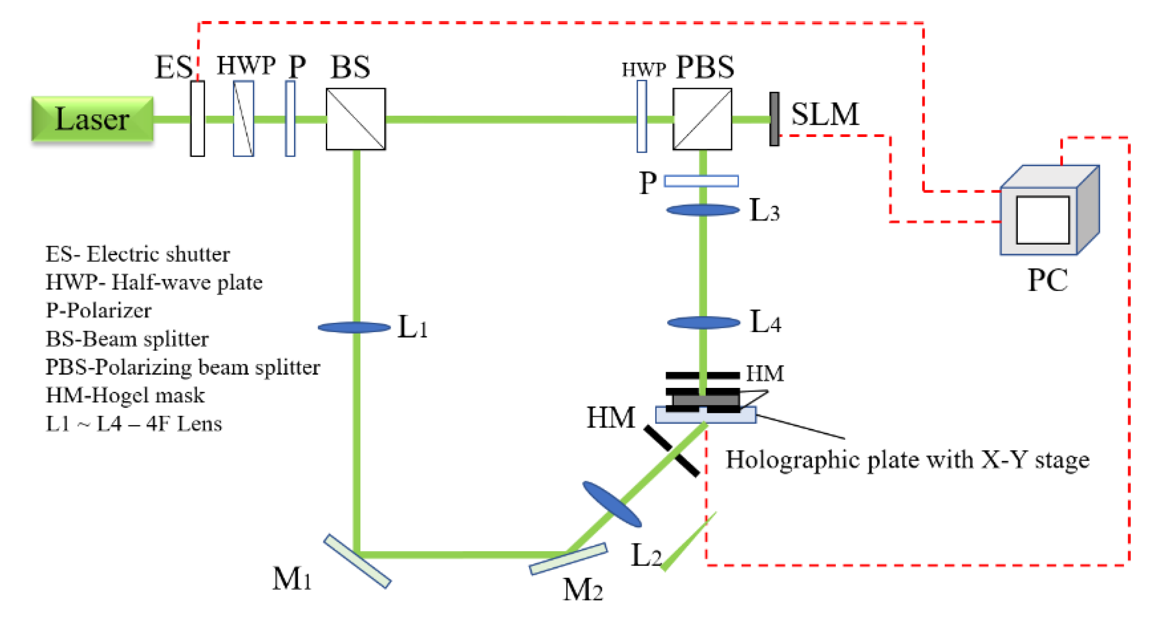
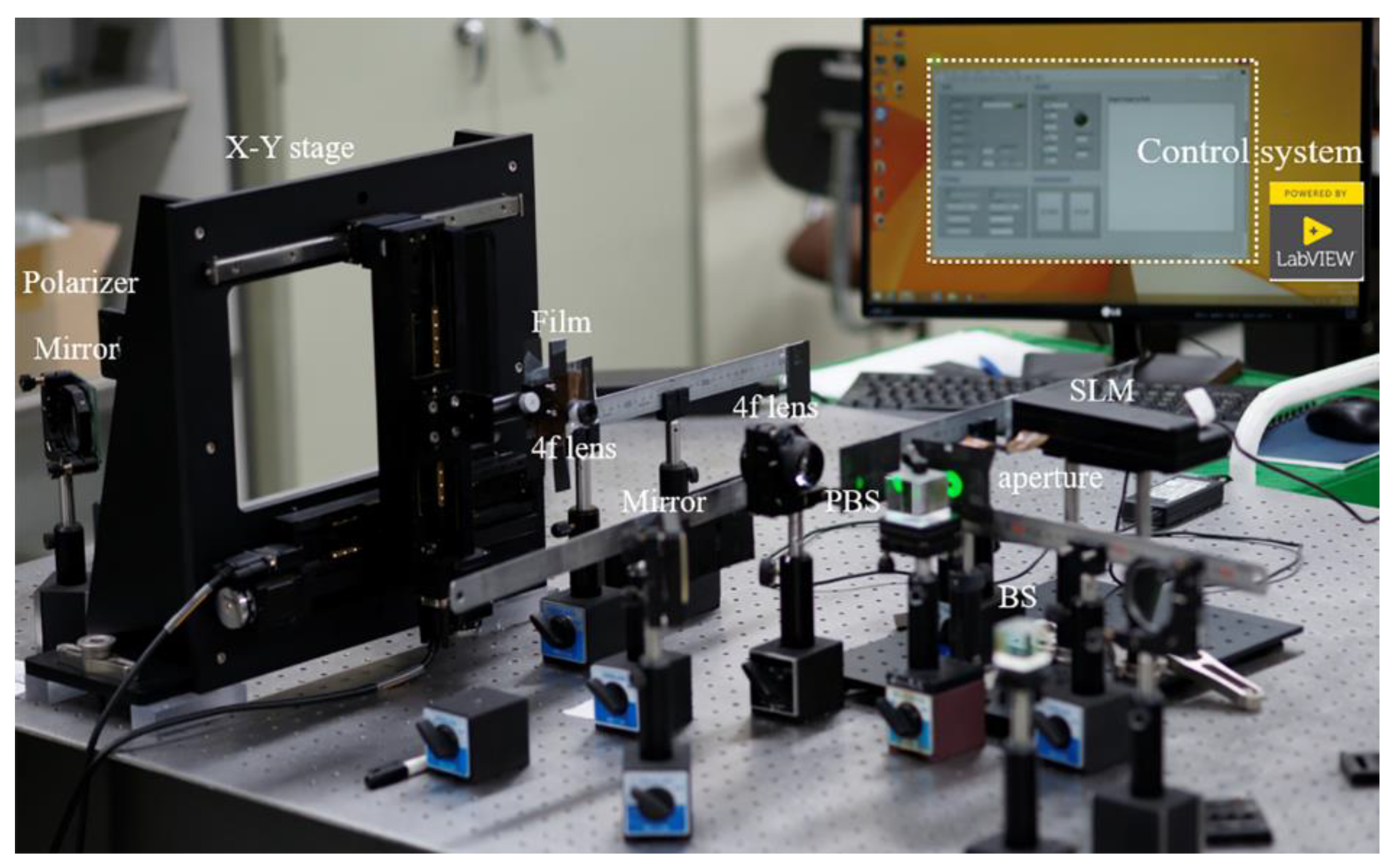
The optical setup and a photograph of the HS printer are shown in Figure 9 and Figure 10, respectively. We applied the general operation principles of the holographic printer, which uses the X-Y translation stage described by Stephen Benton. A 532-nm laser served as the light source. The object beam was spatially modulated by the hogel image displayed on phase-only spatial light modulator. This is a reflective SLM presenting 1920 × 1080 pixels with a pixel pitch of 6.4 µm. The SLM display was de-magnified by lenses L1 and L2 and allowed to interfere with the reference wave. The focal lengths of L1 and L2 were 85 and 25 mm, respectively. The beam is polarised so that all energy is directed by the beam splitter to the spatial light modulator display. Two apertures close to the holographic plate ensure that only the square area of the plate is exposed.
The reference beam is delivered at 45° to the opposite sides of the plate through the long-focal-length lenses L3 and L4. The exposure time was optimised at 0.2 s based on the sensitivity of the Ultimate U08M silver halide holographic material used. When the signal to reference beam energy ratio was 1:1, the diffraction efficiency was relatively high. The holographic plate was installed on a motorised X-Y stage that could move both horizontally and vertically.
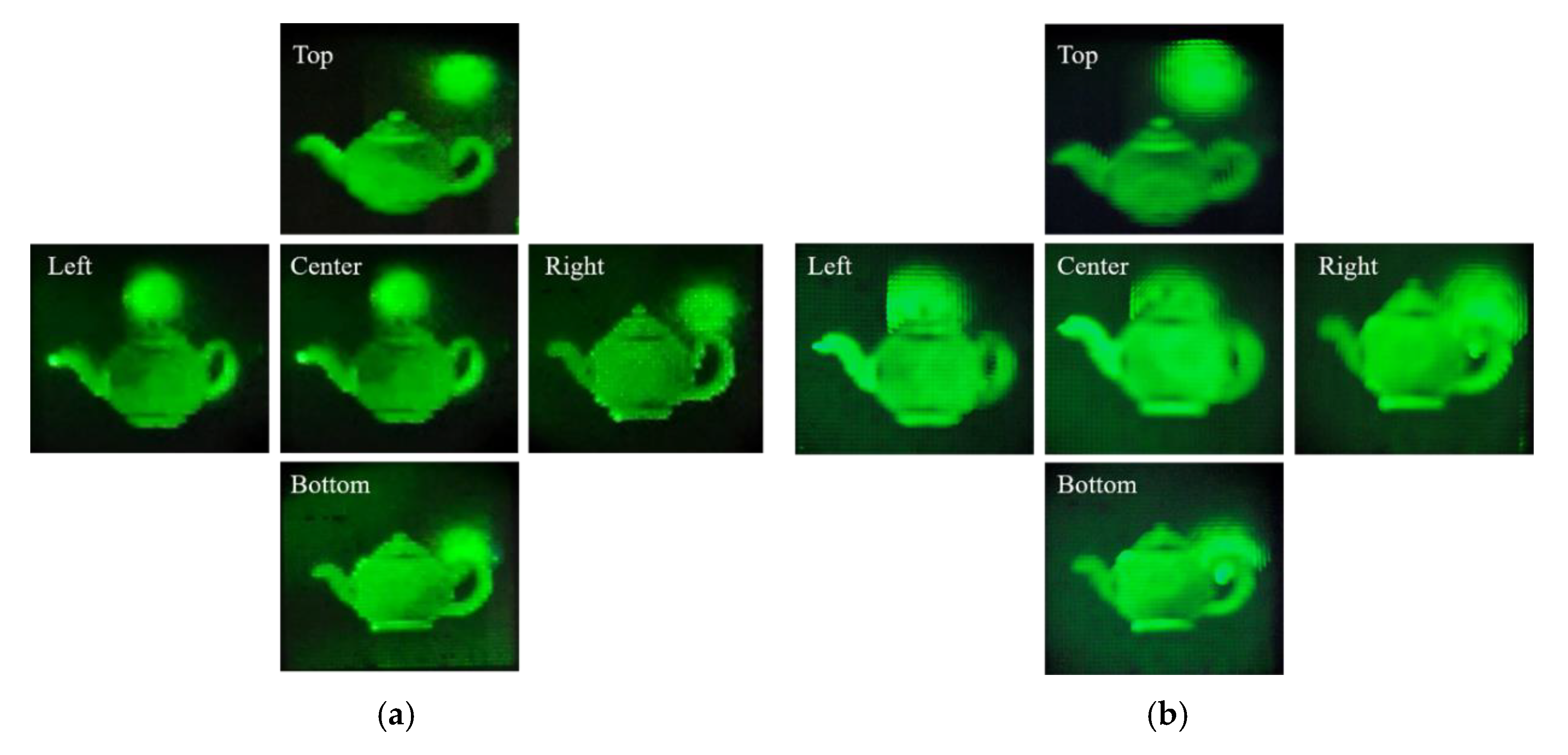
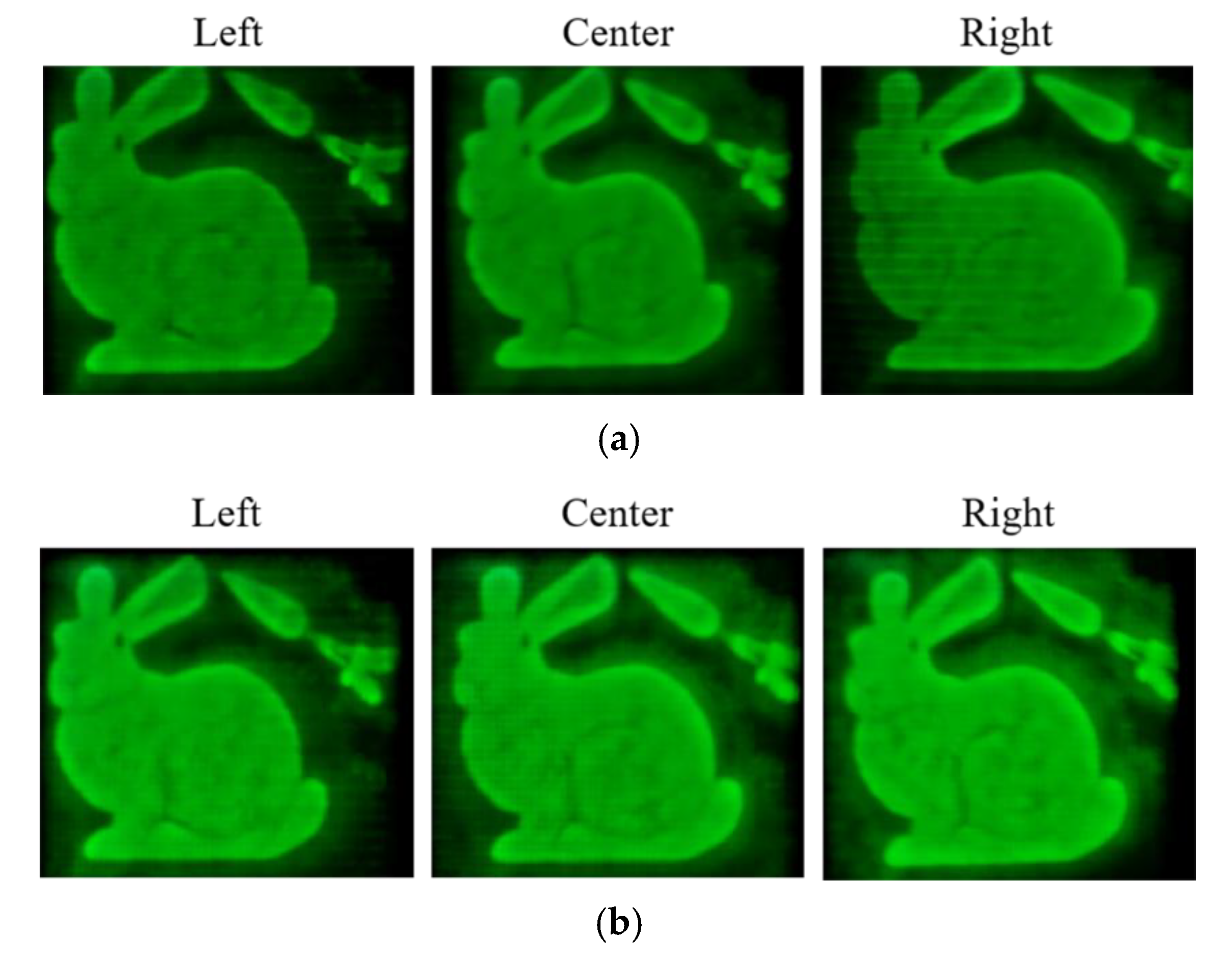
We created a LabVIEW-based application for automatic HS recording in which the SLM display, the X-Y translation stage, and the electrical shutter are controlled simultaneously. Figure 11 and Figure 12 compares the optically reconstructed images for the two synthetic 3D scenes by the conventional and proposed method under the same recording condition. In both cases, 1 × 1 mm hogels were used to synthesise the HSs. The reconstructed images deliver full-parallax information within a field of view of ± 30°.
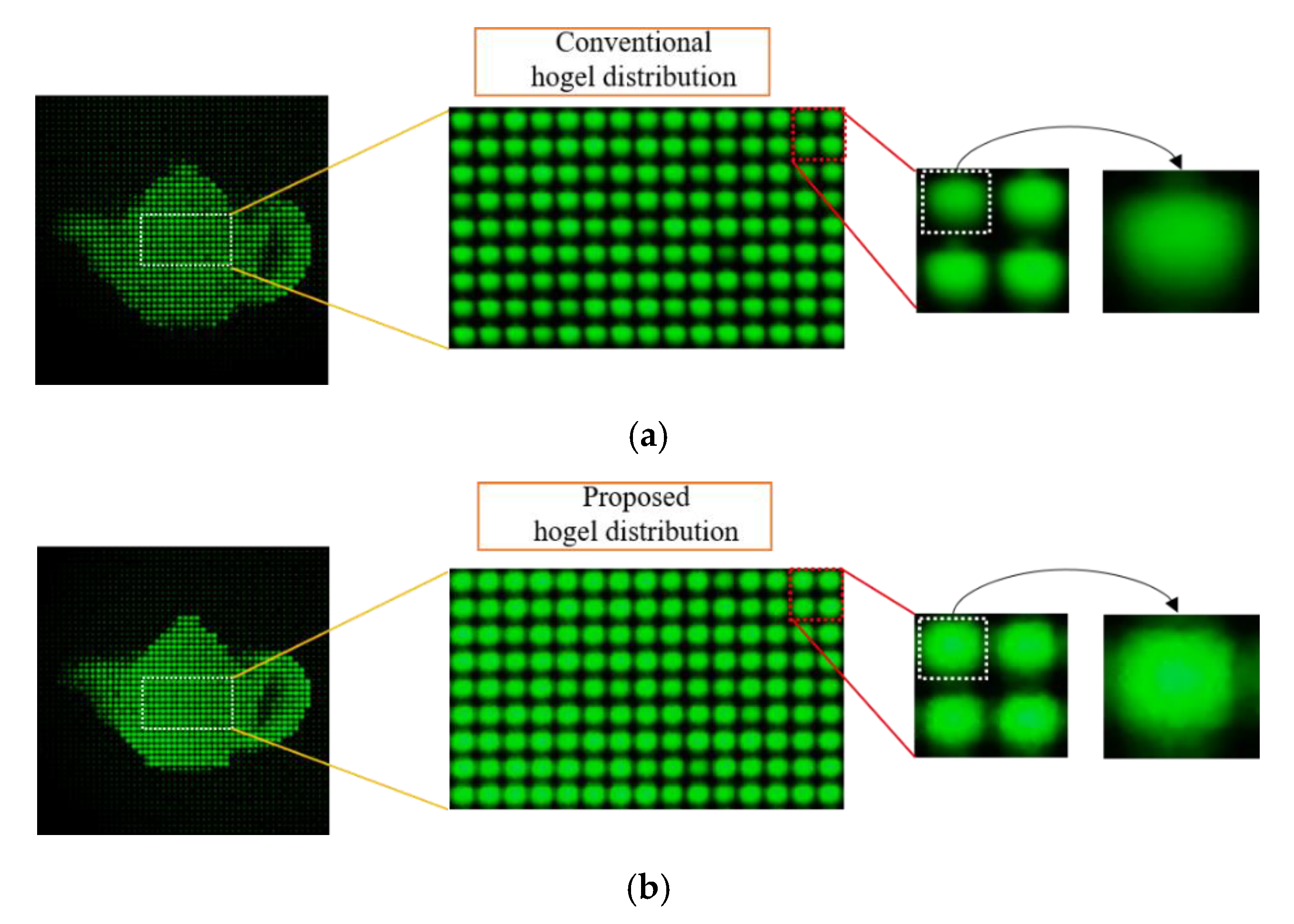
When the reconstructed image of Figure 11 was focused to different depths on the holographic plate, the printed hogels were clear but the 3D scene was blurred (Figure 13). Figure 13 also compares the spatial resolution of reconstructed HSs focused on the holographic plate to distinguish the hogel distributions re-arranged by the conventional and proposed pixel re-arrangement algorithms while maintaining a constant hogel size (1 × 1 mm) in each experiment. In Figure 13a, the pixel resizing technique for conventionally re-arranged hogels increases the distance between adjacent hogels, compromising hogel uniformity, as shown in Figure 13a. A hogel, which are rearranged by the proposed pixel re-arrangement algorithm, have better spatial resolution and provides uniformity between the hogel distance, as shown in Figure 13b. Each hogel on the hologram plane acts as a directional emitter of parallax information. Thus, the hogel emits a set of beams with different intensities on the viewing zone. The viewer’s both eyes intercept light rays emitted in different directions by every hogel recorded on a hologram plane.

4. Conclusions

In this paper, we proposed a hologram synthesis method based on 3D rendering of computer-generated HSs from a reduced number of perspectives with higher resolution. With the purpose of developing a holographic printer, the resolution of re-arranged hogel images was increased without any need for pixel resizing or interpolation by a pixel re-arrangement technique. The proposed pixel re-arrangement algorithm improves the angular resolution of the hogel image without degrading the spatial resolution while maintaining a constant hogel size. The proposed algorithm can employ for an arbitrary number of perspectives. It is simple to change the pixel extraction factor based on captured perspectives. However, one disadvantage of the proposed method is that it takes longer rendering and hogel generation time for higher-resolution perspectives. The experimental results show that the proposed approach is simple and effective for hogel-based holographic content generation from a reduced number of perspectives for holographic stereogram printing. The advanced rendering technique and graphic processing unit (GPU)parallel processing will be used to reduce rendering computation time in our future work.

Author Contributions

Data curation, A.K. Formal analysis, Y.-T.L. and C.-W.S. Investigation, H.K. and S.-H.J. Validation, H.-Y.W. Writing—original draft preparation, E.D. Writing—review and editing, N.K. Data curation, A.K. Formal analysis, Y.-T.L. and C.-W.S. Investigation, H.K. and S.-H.J. Validation, H.-Y.W. Writing–original draft, E.D. Writing–review & editing, N.K. All authors have read and agreed to the published version of the manuscript.

Funding

This research was supported by the Chungbuk National University Korea National University Development Project (2020).

Conflicts of Interest

The authors declare no conflict of interest.

References

  1. Kim, N.; Anh, P.H.; Erdenebat, M.; Alam, M.A.; Kwon, K.-C.; Piao, M.-L.; Lee, J.-H. 3D Dsiplay Technology. Disp. Imaging 2013, 1, 73–95. [Google Scholar]
  2. Kim, N.; Alam, M.A.; Bang, L.T.; Phan, A.-H.; Piao, M.-L.; Erdenebat, M. Advances in the light field displays based on integral imaging and holographic techniques. Chin. Opt. Lett 2014, 12, 060005. [Google Scholar] [CrossRef]
  3. Erdenebat, M.; Lim, Y.-T.; Kwon, K.-C.; Darkhanbaatar, N.; Kim, N. Waveguide-type Head-Mounted Display System for AR application. In State of the Art Virtual Reality and Augmented Reality Knowhow; Mohamudally, N., Ed.; IntechOpen: London, UK, 2018. [Google Scholar]
  4. Kim, Y.; Stoykova, E.; Kang, H.; Hong, S.; Park, J.; Park, J.; Hong, J. Seamless full color holographic printing method based on spatial partitioning of SLM. Opt. Express 2015, 23, 172–182. [Google Scholar] [CrossRef] [PubMed]
  5. Hong, S.; Stoykova, E.; Kang, H.; Kim, Y.; Hong, J.; Park, J.; Park, K. Image-Quality Enhancement for a Holographic Wavefront Color Printer by Adaptive SLM Partitioning. J. Opt. Soc. Korea 2015, 19, 29–37. [Google Scholar] [CrossRef] [Green Version]
  6. Kang, H.; Stoykova, E.; Kim, Y.; Hong, J.; Park, J.; Hong, J. Color wavefront printer with mosaic delivery of primary colors. Opt. Commun. 2015, 350, 47–55. [Google Scholar] [CrossRef]
  7. Kang, H.; Stoykova, E.; Kim, Y.; Hong, J.; Park, J.; Hong, J. Color Holographic Wavefront Printing Technique for Realistic Representation. IEEE Trans. Ind. Inform. 2016, 12, 1590–1598. [Google Scholar] [CrossRef]
  8. Yoshikawa, H.; Yamaguchi, T. Review of Holographic Printers for Computer-Generated Holograms. IEEE Trans. Ind. Inform. 2016, 12, 1584–1589. [Google Scholar] [CrossRef]
  9. Yamaguchi, T.; Miyamoto, O.; Yoshikawa, H. Volume hologram printer to record the wavefront of three-dimensional objects. Opt. Eng. 2012, 51, 075802. [Google Scholar] [CrossRef]
  10. Hong, K.; Park, S.; Yeom, J.; Kim, J.; Chen, N.; Pyun, K.; Choi, C.; Kim, S.; An, J.; Lee, H.-S.; et al. Resolution enhancement of holographic printer using a hogel overlapping method. Opt. Express 2013, 21, 14047–14055. [Google Scholar] [CrossRef] [PubMed]
  11. Su, J.; Yuan, Q.; Huang, Y.; Jiang, X.; Yan, X. Method of single step full parallax synthetic holographic stereogram printing based on effective perspective images’ segmentation and mosaicking. Opt. Express 2017, 25, 23523–23544. [Google Scholar] [CrossRef] [PubMed]
  12. Dashdavaa, E.; Khuderchuluun, A.; Shin, C.-W.; Lim, Y.-T.; Kim, N. Holographic stereogram printer for computer-generated holograms. In Optics, Photonics, and Digital Technologies for Imaging Applications V, Proceedings of the SPIE 10679 Photonics Europe, Strasbourg, France, 25 April 2018; Schelkens, P., Ebrahami, T., Cristobal, G., Eds.; SPIE: Strasbourg, France, 2018; Volume (X)DCLXXIX. [Google Scholar]
  13. Dashdavaa, E.; Khuderchuluun, A.; Lim, Y.-T.; Jeon, S.-H.; Kim, N. Holographic stereogram printing based on digitally designed content generation platform. In Practical Holography XXXIII: Displays, Materials, and Applications, Proceedings of the SPIE OPTO, San Francisco, CA, USA, 2–7 February 2019; Bjelkhagen, H.I., Bove, V.M., Eds.; SPIE: San Francisco, CA, USA, 2019; Volume (X)CMXLIV. [Google Scholar]
  14. Sanchez, A.M.; Prieto, D.V. Design, development and implementation of a low-cost full parallax holoprinter. In Practical Holography XXXII: Displays, Materials, and Applications, Proceedings of the SPIE OPTO, San Francisco, CA, USA, 19 February 2018; Bjelkhagen, H.I., Bove, V.M., Eds.; SPIE: San Francisco, CA, USA, 2018; Volume CVDLXXX. [Google Scholar]
  15. Bjelkhagen, H.; Brotherton-Ratcliffe, D. Ultra-Realistic Imaging: Advanced Techniques in Analog and Digital Colour Holography, 1st ed.; CRC Press: Boca Raton, FL, USA, 2013. [Google Scholar]
  16. Pei, C.; Yan, X.-P.; Jiang, X. Computer-generated phase-modulated full parallax holographic stereograms without conjugate images. Opt. Eng. 2014, 53, 103105. [Google Scholar] [CrossRef]
  17. Goncharsky, A.; Goncharsky, A.; Durlevich, S. High-resolution full-parallax computer-generated holographic stereogram created by e-beam technology. Opt. Eng. 2017, 56, 063105. [Google Scholar] [CrossRef]
  18. Blanche, P.-A.J.; Bigler, C.M.; Ka, J.-W.; Peyghambarian, N.N. Fast and continuous recording of refreshable holographic stereograms. Opt. Eng. 2018, 57, 061608. [Google Scholar] [CrossRef]
  19. Park, J.-H.; Askari, M. Non-hogel-based computer-generated hologram from light field using complex field recovery technique from Wigner distribution function. Opt. Express 2019, 27, 2562–2574. [Google Scholar] [CrossRef] [PubMed]
  20. Fan, F.; Jiang, X.; Yang, X.; Wen, J.; Chen, S.; Zhang, T.; Han, C. Holographic Element-Based Effective Perspective Image Segmentation and Mosaicking Holographic Stereogram Printing. Appl. Sci. 2019, 9, 920. [Google Scholar] [CrossRef] [Green Version]
  21. Su, J.; Yan, X.; Huang, Y.; Jiang, X.; Chen, Y.; Zhang, T. Progress in the Synthetic Holographic Stereogram Printing Technique. Appl. Sci. 2018, 8, 851. [Google Scholar] [CrossRef] [Green Version]
  22. Shi, L.; Huang, F.-C.; Lopes, W.; Matusik, W.; Luebke, D. Near-eye light field holographic rendering with spherical waves for wide field of view interactive 3D computer graphics. ACM Trans. Graph. 2017, 36, 1–17. [Google Scholar] [CrossRef]
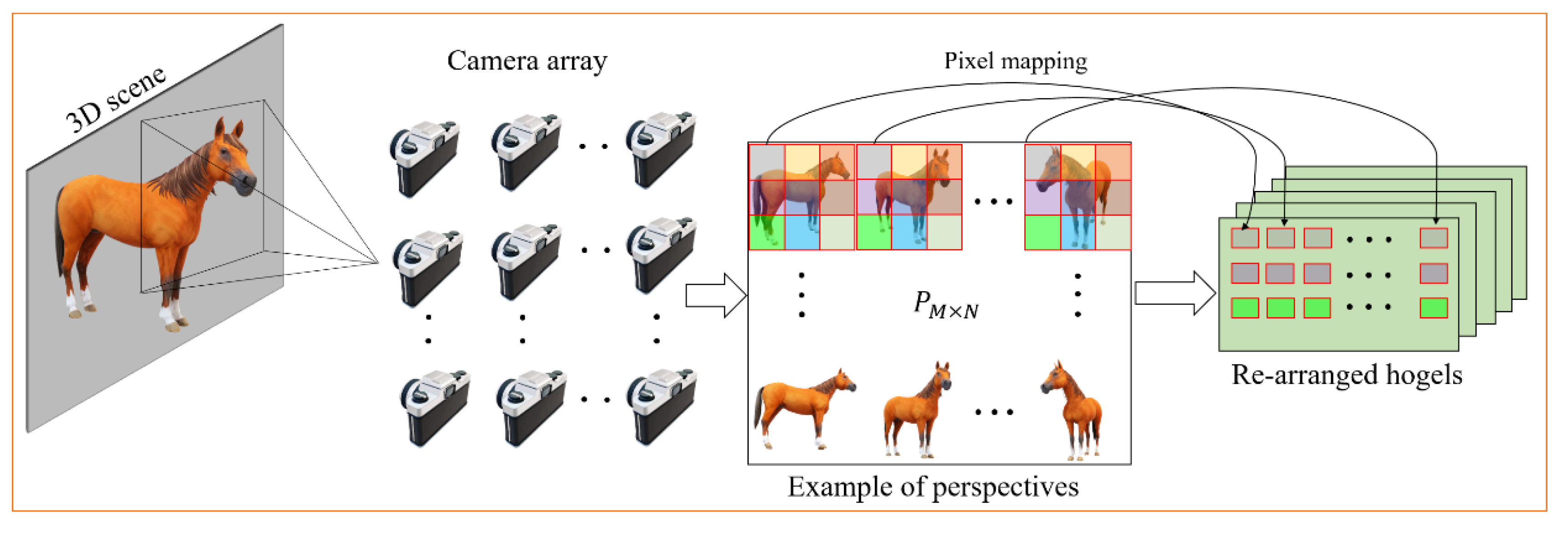
Figure 1. Schematic configuration of hogel-based holographic stereogram synthetization.
Applsci 10 08088 g001
Figure 2. Geometry used for capturing perspectives by the re-centering camera model.
Applsci 10 08088 g002
Figure 3. Conventional pixel re-arrangement process from captured perspectives.
Applsci 10 08088 g003
Figure 4. Proposed pixel re-arrangement algorithm from captured perspectives.
Applsci 10 08088 g004
Figure 5. 3D scene and hologram synthetization from full-parallax HS: (a) 3D object “Teapot and sphere.” (b) 3D object “Bunny and carrot.”
Applsci 10 08088 g005aApplsci 10 08088 g005b
Figure 6. Comparison of rendered perspectives in terms of pixel disparity: (a) conventional method and (b) proposed method.
Applsci 10 08088 g006
Figure 7. Numerical reconstruction of hologram synthesis at an increasing number of iterations in iterative Fourier transform algorithm: (a) phase distributions, (b) conventional hogel re-arrangement after pixel interpolation, (c) views by proposed pixel-mapping algorithm for the object “Teapot and sphere,” (d) views by a proposed pixel re-arrangement algorithm for the object “Bunny and carrot.”
Applsci 10 08088 g007
Figure 8. Peak signal-to-noise ratio (PSNR) comparison for visual quality evaluation.
Applsci 10 08088 g008
Figure 9. Optical setup for holographic stereogram printing.
Applsci 10 08088 g009
Figure 10. Photograph of holographic stereogram printing.
Applsci 10 08088 g010
Figure 11. Optical reconstruction of full-parallax holographic stereogram for object “Teapot and sphere” (a) conventional method and (b) proposed method.
Applsci 10 08088 g011
Figure 12. Optical reconstruction of the second object “Bunny and carrot”: (a) conventional method and (b) proposed method.
Applsci 10 08088 g012
Figure 13. Spatial resolution comparison: (a) conventional method and (b) proposed method.
Applsci 10 08088 g013
Table 1. Computation times.
MethodsRendering(s)Hogel Generation(s) CGH Pattern(s) IFTA(s)Recording(s)Total Time(s)
Conventional method13751208573230005384
Proposed method229127597564630008852
Publisher’s Note: MDPI stays neutral with regard to jurisdictional claims in published maps and institutional affiliations.