Article

Study of Non-Periodic Pinhole Array Filter for Decreasing High-Order Noise for Compact Holographic Display

1
School of Electrical Engineering, Korea Advanced Institute of Science and Technology, Daejeon 34141, Korea
2
Spatial Optical Information Research Center, Korea Photonics Technology Institute, Gwangju 61007, Korea
*
Author to whom correspondence should be addressed.
Appl. Sci. 2020, 10(23), 8671; https://doi.org/10.3390/app10238671
Submission received: 11 November 2020 / Revised: 30 November 2020 / Accepted: 1 December 2020 / Published: 4 December 2020
(This article belongs to the Special Issue Practical Computer-Generated Hologram for 3D Display)

Abstract

:
The non-periodic pinhole array filtering of a spatial light modulator (SLM) is proposed for filtering the high-order noise and DC noise of a holographic display. Conventionally, DC and high-order noise sources are filtered by a 4f filtering system. Because the 4f filtering system requires a long optical path length, noise filtering is a stumbling block when attempting to realize a compact holographic display. By contrast, the proposed method simply uses a thin filter fabricated by photolithography. In order to verify this concept, we confirmed the feasibility of the filter with a numerical simulation and with a custom-made non-periodic pinhole array filter used in a practical experiment. The proposed method was shown to have the potential to be used in applications ranging from compact wearable devices to table-top holographic displays.

1. Introduction

A computer-generated hologram (CGH) is a useful form of technology in various industry fields, such as displays, the medical field, the military, and many culture-related fields, among others. Specifically, the holographic display, a promising candidate as a next-generation 3D display, forms points and faces in the air by modulating the amplitude and phase [1]. However, holographic displays have inevitable problems, such as twin images, along with direct current (DC) noise, high-order noise, and speckle noise sources. Among them, high-order noise and the DC noise are caused by the periodic pixels of the spatial light modulator (SLM) used [2,3]. Conventionally, a 4f filtering system has been used for filtering DC and high-order noise types, as shown in Figure 1a [4,5,6]. However, the optical path length of a 4f filtering system is too long for it to be implemented in a compact holographic display. For this reason, several studies have attempted to filter out noise sources without using a 4f filtering system [2,3,7]. The fundamental solution involves forming the pixels into a non-periodic structure; nevertheless, most previous studies have focused on modulating the signal based on periodic pixels. Research on obtaining more than the Nyquist frequency through random scattering materials has been conducted in the field of compressive sensing [8,9]. Especially in the field of displays, it has been reported that the viewing angle can be widened through a pinhole [10], and the concept of removing high order through a random pinhole has been reported [11,12]. In this study, we present answers to the following question: “How much will high-order and DC noise disappear if pixels can be rearranged into a non-periodic structure?”. We analyzed the decrease in high order from adjusting the degree of the random deviation of the pinhole from the center of the LCD pixel. The result was successfully verified in a numerical simulation and a practical experiment.

2. Approach

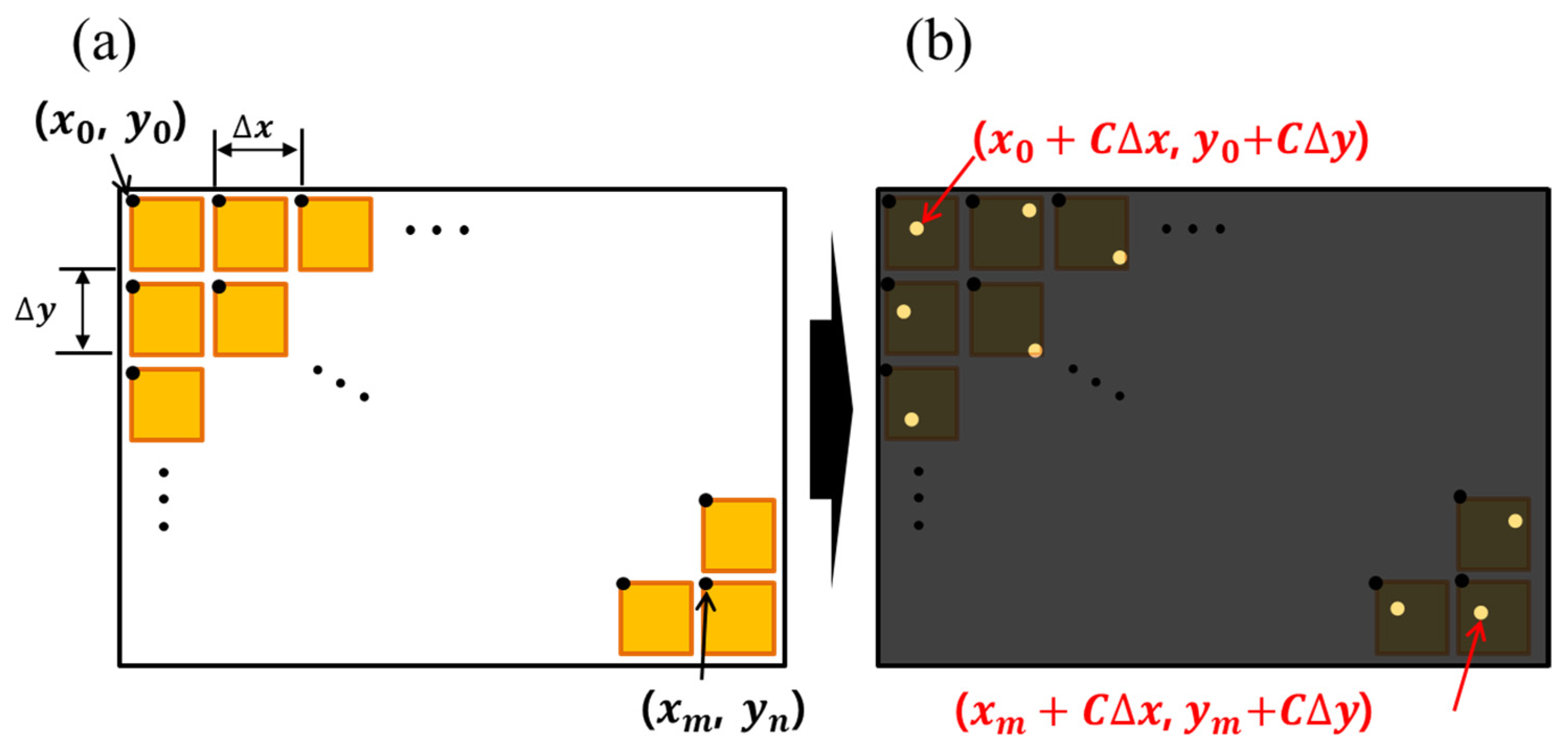
First, a numerical simulation of high-order diffraction on non-periodic pixels was conducted in the Python environment. With periodic pixels, the intensity of DC noise is determined by the ratio between the active area and the dead space on the SLM. However, the proposed method causes the pixels and the dead space to exist in a non-periodic structure, as shown in Figure 2. Thus, both high-order and DC noise are suppressed at the same ratio. There are several hologram calculation methods, such as the point cloud, depth layer, ray-tracing, and triangular mesh methods. Here, the point cloud method was used to obtain a hologram from the virtual objects in this study. The point cloud method is easy and intuitive to implement with non-periodic pixels, as it directly finds the phase value by calculating the distance from the points to the hologram plane. By contrast, a Fourier transform-based hologram should use the NUFFT (non-uniform fast Fourier transform) method [8]. However, the two methods produce similar results. As shown in Figure 2, the proposed point cloud hologram based on non-periodic pixels can be expressed as follows:
P j ( u , v , z ) = 1 j A ( e i 2 π D / λ D )
D = { x 0 ( x + C Δ x ) } 2 + { y 0 ( y + C Δ y ) } 2 + ( z 0 z ) 2
where A, Δ x , Δ y , and λ denote the amplitude of the point, horizontal pixel pitch, vertical pixel pitch, and incident beam wavelength, respectively. D is the distance from the points ( x 0 , y 0 , z 0 ) to the non-periodic pixel hologram plane ( x + C Δ x , y + C Δ y , z ) , where C is a random number generator that can produce 0 to C values, randomly. If C equals 0, the SLM becomes periodic pixels, whereas if C equals 1, the SLM becomes fully non-periodic pixels.

3. Experiment and Result

All the variables in this study are shown in Table 1. In the numerical simulation, the diffraction order’s intensity of a single point located 50 cm from the hologram plane was calculated, as shown in Figure 3.
Figure 3a shows the conventional periodic pixels, for which the C value equals 0 and where the first-order intensity is 0.77, whereas Figure 3b shows fully non-periodic pixels, for which the C value equals 1 and the first-order intensity is around 0.11. If the C value exceeds 1.0, the first-order relative intensity converges to 0, as shown in Table 2. However, such a condition is practically impossible, as the non-periodic pinhole array filter is attached within the pixel area, as shown in Figure 2. Hence, here, we only consider C values ranging from 0 to 1.
DC noise typically stems from a black matrix (i.e., dead space). Unfortunately, the fill factor of the best Liquid crystal on silicon SLM is not 100% but 90%. Hence, an additional bulky optical system is inevitable. However, the proposed method reorganizes the pixels and the black matrix into a non-periodic structure simultaneously. Therefore, the DC noise also decreases identically to how the high-order noise does in this case. This is one of the reasons why the proposed idea has potential.
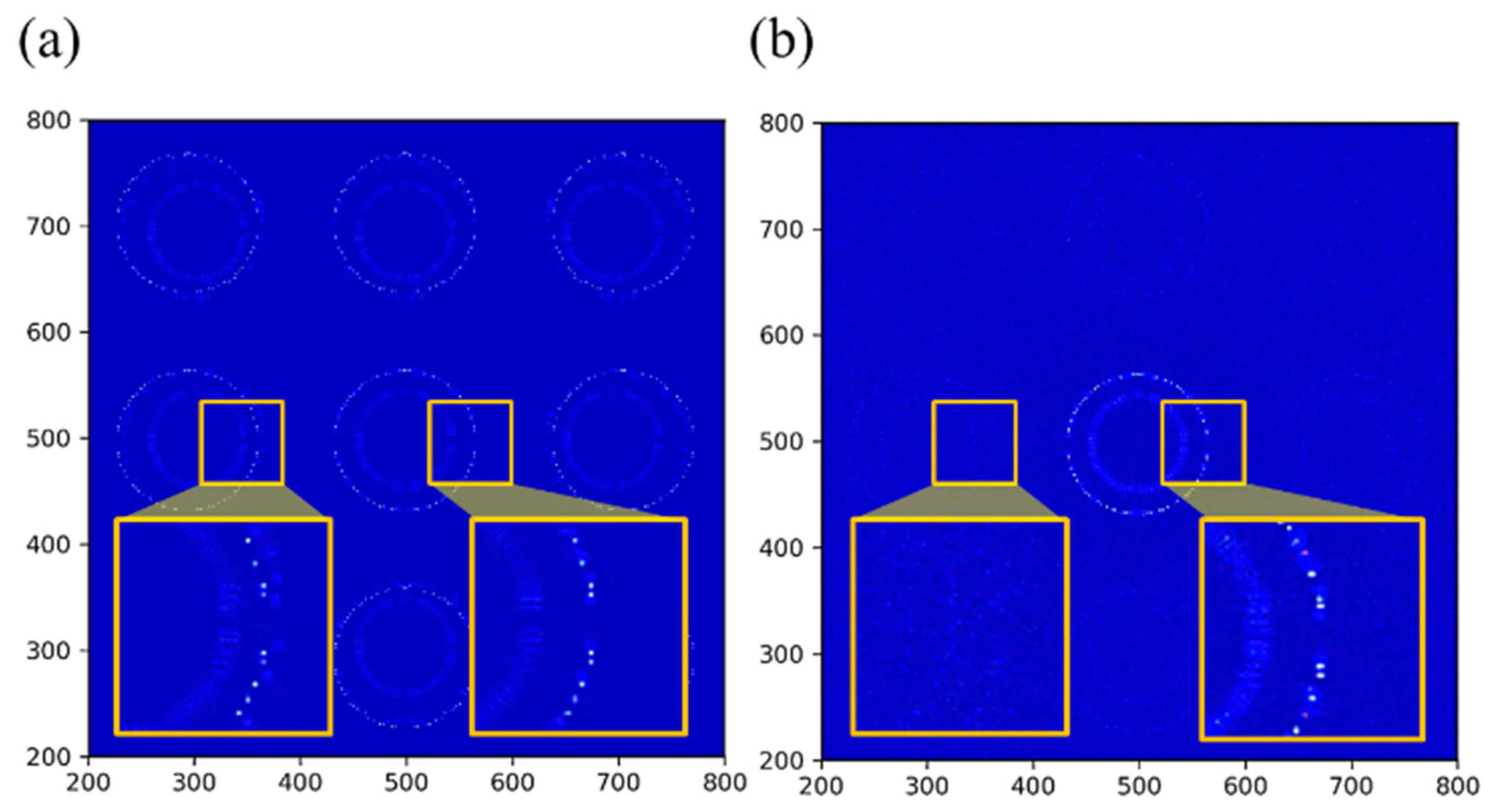
In order to verify the feasibility of the proposed method practically, a ring point cloud model consisting of 66 points was reconstructed with an equivalent method via a single-point simulation. The inner ring and outer rings were positioned at 50 and 51 cm from the hologram plane, respectively. The observation was then made at the outer ring position. As a result, the high-order images of the non-periodic pixels vanished, as shown in Figure 4.
In this paper, an LCG (linear congruential generator), commonly used as the random number function in C++, MATLAB, and Python, was used to produce the random numbers. However, unfortunately, the results of the LCG exhibited periodicity and tended to be biased to one side [8]. Therefore, it cannot be said that the results of this study are optimal. If there is a more exquisite random number generator, the quality of the proposed idea will be improved. In addition, when the reconstructed hologram approaches the hologram plane, the background noise increases slightly. Usually, the reconstructed hologram is duplicated by high-order diffraction due to the periodicity of the pixels. By contrast, the proposed hologram is calculated based on non-periodic pixels; hence, it has no high-order diffraction and no duplicated holograms, but the hologram data are regarded as noise in the high-order diffraction region. Therefore, as shown in Figure 5, the background intensity of the single-point hologram decreases according to an increase in the hologram reconstruction distance.
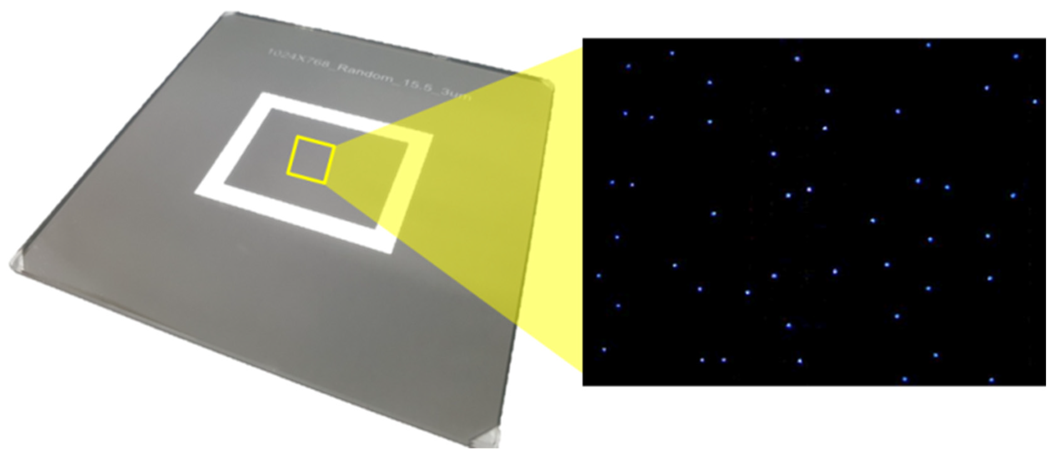
In order to perform a practical experiment, a custom-made pinhole array mask with every pinhole having a diameter of 3 μm was fabricated by photolithography, as shown in Figure 6. The mask was then carefully attached to the SLM by a custom-made alignment stage.
The experimental conditions were identical to those in the numerical simulation, apart from the C value. The reconstructed hologram was captured with a digital camera. Figure 7 shows the optical system used in the experiment. In addition, the C value in the practical context was determined as the effective pixel aperture divided by the pixel pitch. The effective pixel aperture was determined by the fill factor of the spatial light modulator. Our spatial light modulator had a 58% fill factor with a 36 μm pixel pitch; hence, the effective pixel aperture was only 20.88 μm. Therefore, unfortunately, the C value could not exceed 0.58 in this experiment. Although the random pinhole array filter was created with a C value of 0.6, which was suitable for our SLM, Figure 8a,b demonstrate feasible performance in that the high-order images were eliminated.
Due to the small pixel size of the pinhole, the diffraction efficiency of the system decreased. The light intensity was measured using a laser power meter (Sanwa instrument, Tokyo, Japan). When there was no pinhole array, the intensity of the light before the SLM was 1.453 mw and after the SLM was 0.723 mw, and the light passing through with the random pinhole array filter was measured as 5.38 μm. The diffraction efficiency ratio with and without the pinhole array was 0.744%.

4. Conclusions

In conclusion, the proposed non-periodic pinhole array filtering method of the spatial light modulator was verified with a numerical simulation and a practical experiment in this study. First, the high-order intensity distribution was verified by varying the C value. Thus, the first-order intensity became seven times lower compared to the periodic intensity when the SLM fully became non-periodic pixels. Although non-periodic pixels eliminate high-order diffraction, a hologram based on non-periodic pixels acts as noise in the high-order region. Hence, the noise tends to increase in the high-order region when the reconstruction distance is closer to the hologram plane. Finally, a custom-made pinhole array mask was fabricated and attached to the SLM to reorganize the pixels. As a result, the practically reconstructed hologram showed results equivalent to those from the simulation. The proposed method was not able to solve all the noise problems in the holographic display. However, we believe that a lens-less holographic display will be realized by combining the results here with other ideas.

Author Contributions

Conceptualization Y.K.K. and J.S.L.; methodology Y.K.K. and J.S.L.; software W.J.R. and J.S.L.; writing–original draft Y.K.K. and J.S.L.; writing–review and editing, Y.K.K., W.J.R. and J.S.L.; supervision, J.S.L. All authors have read and agreed to the published version of the manuscript.

Funding

This research was funded by an Institute for Information & Communication Technology Promotion (IITP) grant funded by the Korean government (MSIP) (No. 2020-0-01842, Development of holographic lithography equipment and printing technology for security and books).

Conflicts of Interest

The authors declare no conflict of interest.

References

  1. Xiong, J.; Yin, K.; Li, K.; Wu, S. Holographic Optical Elements for Augmented Reality: Principles, Present Status, and Future Perspectives. Adv. Photonics Res. 2020. [Google Scholar] [CrossRef]
  2. Zang, H.; Xie, J.; Wang, Y. Elimination of a zero-order beam induced by a pixelated spatial light modulator for holographic projection. Appl. Opt. 2009, 48, 5834–5841. [Google Scholar] [CrossRef] [PubMed]
  3. Bang, K.; Jang, C.; Lee, B. Compact noise-filtering volume gratings for holographic displays. Opt. Lett. 2019, 44, 2133–2136. [Google Scholar] [CrossRef] [PubMed]
  4. Moon, E.; Kim, M.; Roh, J.; Kim, H.; Hahn, J. Holographic head-mounted display with RGB light emitting diode light source. Opt. Express 2014, 22, 6526–6534. [Google Scholar] [CrossRef] [PubMed]
  5. Lee, J.; Kim, Y.; Won, Y. Time multiplexing technique of holographic view and Maxwellian view using a liquid lens in the optical see-through head mounted display. Opt. Express 2018, 26, 2149–2159. [Google Scholar] [CrossRef] [PubMed]
  6. Sun, P.; Chang, S.; Liu, S.; Tao, X.; Wang, C.; Zheng, Z. Holographic near-eye display system based on double-convergence light Gerchberg-Saxton algorithm. Opt. Express 2018, 26, 1014. [Google Scholar] [CrossRef] [PubMed]
  7. Maimone, A.; Georgiou, A.; Kollin, J.S. Holographic near-eye displays for virtual and augmented reality. ACM Trans. Graph. 2017, 36, 1–16. [Google Scholar] [CrossRef]
  8. Candès, E.J.; Romberg, J.; Tao, T. Robust uncertainty principles: Exact signal reconstruction from highly incomplete frequency information. IEEE Trans. Inf. Theory 2006, 52, 489–509. [Google Scholar] [CrossRef] [Green Version]
  9. Liutkus, A.; Martina, D.; Popoff, S.; Chardon, G.; Katz, O.; Lerosey, G.; Gigan, S.; Daudet, L.; Carron, I. Imaging with nature: Compressive imaging using a multiply scattering medium. Sci. Rep. 2014, 4, 5552. [Google Scholar] [CrossRef] [PubMed] [Green Version]
  10. Genet, C.; Ebbesen, T.W. Light in tiny holes. Nature 2007, 445, 39–46. [Google Scholar] [CrossRef] [PubMed]
  11. Wang, S.; Li, Z.; Wu, J.; Wang, Z. Accelerated near-field algorithm of sparse apertures by non-uniform fast Fourier transform. Opt. Express. 2019, 14, 19102–19118. [Google Scholar] [CrossRef] [PubMed]
  12. Park, J.; Lee, K.; Park, Y. Ultrathin wide-angle large-area digital 3D holographic display using a non-periodic photon sieve. Nat. Commun. 2019, 10, 1304. [Google Scholar] [CrossRef] [PubMed] [Green Version]
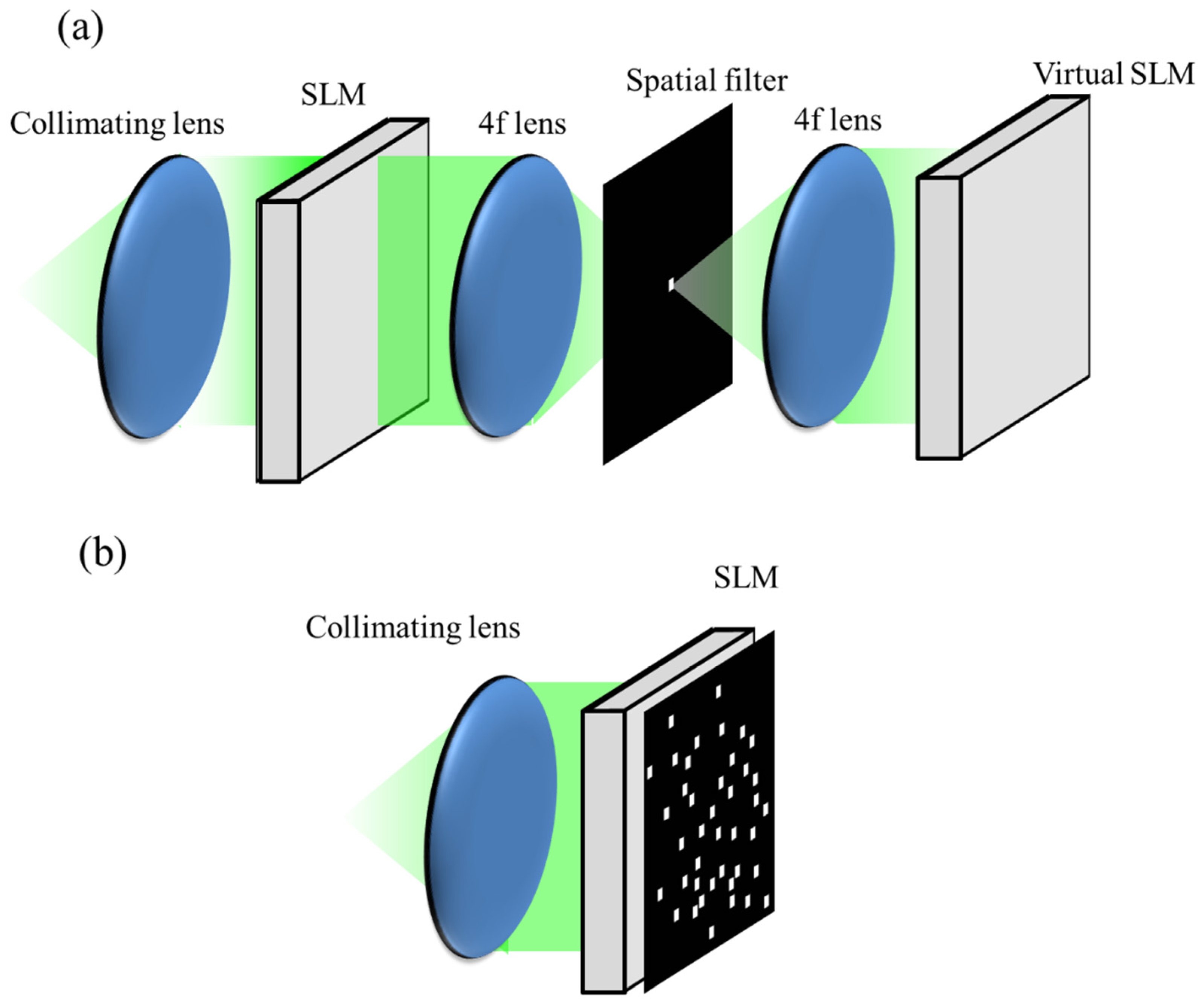
Figure 1. Holographic display configuration using (a) conventional 4f filtering optics and (b) the proposed non-periodic pinhole array filter.
Applsci 10 08671 g001
Figure 2. Basic schematics of (a) conventional periodic pixels and (b) the proposed non-periodic pinhole array filtering process.
Applsci 10 08671 g002
Figure 3. Numerical simulation of a single-point hologram with (a) conventional periodic pixels and (b) fully non-periodic pixels.
Applsci 10 08671 g003
Figure 4. Numerical simulation of a point cloud hologram with (a) conventional periodic pixels and (b) fully non-periodic pixels.
Applsci 10 08671 g004
Figure 5. The intensity distribution of a single-point hologram according to the reconstruction distance (log scale).
Applsci 10 08671 g005
Figure 6. Magnified image of the custom-made non-periodic pinhole array filter.
Applsci 10 08671 g006
Figure 7. Optical configuration used in the experiment. (BS: Beam-Splitter, LP: Linear Polarizer).
Applsci 10 08671 g007
Figure 8. (a) Reconstructed holographic image without using a filter and (b) with the proposed non-periodic pinhole array filter.
Applsci 10 08671 g008
Table 1. Experimental conditions.
SLM(LC-2012)Light Source
Resolution1024 × 768Wavelength532 nm
Pixel pitch36 μmModeTEM00
Fill factor58%Point Cloud Model
TypeTransmissive#Points66
Distance50~50.1 cm
Table 2. High order’s relative intensity according to the C value.
C Value±2nd ±1st
0.00.620.77
0.20.460.56
0.40.0660.31
0.60.0150.22
0.80.0470.13
1.00.0180.11
1.20.0080.05
1.40.0080.02
Publisher’s Note: MDPI stays neutral with regard to jurisdictional claims in published maps and institutional affiliations.