Abstract
The modular multilevel converter (MMC) has been widely adopted in high voltage direct current (HVDC) transmission systems due to its significant advantages. MMC-HVDC is developing towards multi-terminal direct current (MTDC) power grid for reliability enhancement. However, there exist a huge amplitude and a steep rise in fault current due to the low impedances of DC lines and MMCs, which threaten the security and reliability of the DC power grids. It is necessary to restrain the DC short circuit current in order to ensure the safe and stable operation of DC power grids. This paper gives a comprehensive review and evaluation of the proposed DC short-circuit current analysis and suppression techniques used in MMC-based MTDC power girds, in terms of MMC modeling, short circuit calculation, and suppression method. In addition, future trends of countermeasures to short circuit current in MMC-based MTDC power grids are also discussed.
1. Introduction
With the development of global power interconnection, the requirements of long-distance power transmission and asynchronous power grids’ interconnection are increasing. In order to meet these requirements, high-voltage direct current (HVDC) technology is playing a significant role in future global power interconnection [1]. Among all of the converter topologies, the modular multilevel converter (MMC), which was first introduced in 2001, is considered to be the most promising converter topology for HVDC transmission systems [2] due to its advantages of no commutation failure, flexible active and reactive power control, low switching operational frequency, and high output waveform quality, etc. [3].
MMC-HVDC is widely applied in renewable energy integration [4], the construction of DC grids, connection to weak power systems, large city power supply, asynchronous power grids’ interconnection [5], and so on [6]. Presently, there are more than thirty MMC-HVDC projects in operation or under construction throughout the world, some of which commissioned in recent years are listed in Table 1. With the ability of changing power flow direction without reversing the voltage polarity, MMC-HVDC is gradually developing towards a multi-terminal direct current (MTDC) power grid [7]. The increasing terminal number of MMC-HVDC systems in China has verified this trend. By providing the possibility of interconnections between asynchronous power systems and various renewable energy resources [8], MMC-based MTDC power grids can potentially enhance the reliability of the AC and DC systems and improve the flexibility and economy of power dispatching [7]. It is playing an important role in future development of smart grids and the global power interconnection [9,10,11,12,13,14].

Table 1.
Modular multilevel converter-high voltage direct current (MMC-HVDC) projects in operation or under construction world wide.
However, the application of MMC-based MTDC power grids brings several technical challenges. One major challenge is the massive DC short-circuit fault currents. When compared with traditional AC systems, the impedances of DC lines and MMCs are much smaller. Once DC short-circuit faults occur, the capacitors in the submodules of MMCs discharge immediately and large short circuit currents are fed to the fault point through the DC transmission lines and the power electronic devices [13]. A typical DC pole-to-pole short circuit of an MMC-based MTDC power grid is shown in Figure 1. It can be seen from Figure 1 that the short-circuit current rapidly rises within a few milliseconds with a peak value of more than after the DC short circuit fault occurs. DC current breakers are not commonly available for interrupting short-circuit currents due to the absence of a natural current zero crossing in DC systems, and they have very limited ratings for HVDC applications [15]. It is necessary to analyze and suppress the short-circuit current in order to ensure that the DC current breakers can isolate the fault line.
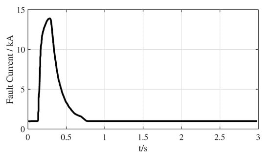
Figure 1.
A typical DC pole-to-pole short circuit of MMC-based multi-terminal direct current (MTDC) power grid.
Modelling, short-circuit current calculation methods, and suppression methods are essential in the investigation of countermeasures to the DC short-circuit current in MMC-based MTDC power grids. This paper gives a comprehensive review and evaluation of short-circuit current analysis and countermeasures in MMC-based MTDC power grids. The main contributions of this paper are: first, this paper offers an up-to-date review of the state of MMC-HVDC modelling; second, the existing MMC-based MTDC power grid short-circuit current calculation method is introduced; and third, this paper classifies the existing short-circuit current suppression methods, especially the latest achievements in this area. The analysis results and discussions show the shortcomings in the current research and provide future research directions that are based on this work.
This paper is organized, as follows: Section 2 makes a brief introduction of MMC-HVDC; Section 3 presents the classification of MMC-HVDC modeling methods; Section 4 introduces several short circuit current calculation methods, and classifies the existing short-circuit current suppression methods for MMC-based MTDC power grids; and, Section 5 concludes this paper and discusses future research trends that are based on this work.
2. A Brief Introduction of MMC
Figure 2a shows a general structure of a three-phase MMC. Each bridge arm of the MMC consists of an arm reactor and N series-connected sub-modules (SMs). is the equivalent resistance of the bridge arm. is the DC voltage of MMC. The multilevel output voltage is generated by controlling the number of inserted SMs in the bridge arm.
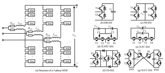
Figure 2.
Structure of a three-phase MMC with various sub-modules (SMs).
Different topologies of SMs for MMCs have been proposed and investigated, including the half-bridge (HB), the full-bridge (FB), the clamp-double (CD). and the three-level/five-level cross-connected (3LCC/5LCC) SMs [16,17,18] as shown in Figure 2b–g. These SM topologies are available for the MMC structure that is shown in Figure 2a. The features of each topology are summarized, as follows:
- HB circuit: the HB-SM is inserted or bypassed by turning on or , respectively. When the SM is switched-on or in inserted state, its output voltage equals to its capacitor voltage . Otherwise, when the SM is switched-off or in bypassed state, the output voltage is 0 [18].
- FB circuit: the operation state of FB-SM is determined by the switching states of the four switches to . When in switched-on/inserted state, the output voltage equals to the capacitor voltage . Otherwise, it is 0. The costs of an MMC based on the FB-SMs are higher than that of an MMC based on the HB-SMs due to the increased number of switches in each SM [16].
- CD circuit: a CD-SM consists of two HB-SMs, two additional diodes, and one extra integrated gate bipolar transistor (IGBT) with its anti-parallel diode. During normal operation, the switch is always in conduction state and the dynamics of CD-SM are equivalent to two series connected HB-SMs [16].
- 3LCC circuit: there are two different types of 3LCC-SM, three level neutral-point-clamped (NPC), and three-level flying capacitor (FC). For a three-level FC-SM, its power losses are similar with a HB-SM. The power losses of NPC-SM are higher than the HB-SM and lower than the FB-SM [3]. The 3LCC-SM based MMC is not very attractive from the perspective of manufacturing and control [17].
- 5LCC circuit: there are two HB-SMs connected back-to-back by two extra IGBTs with their anti-parallel diodes in a 5LCC-SM. Its power losses are the same as the CD-SM [17].
Table 2 provides a comparison of different SM topologies, in terms of output voltage levels, DC short circuit fault ride through capability, and power losses. Section 4 will discuss the DC short circuit fault ride through capability of each SM topology.

Table 2.
Comparison of different SM topologies.
There are different dynamic characteristics and operational demands for various SM topologies. It is necessary to establish the MMC model that covers different SM topologies for further dynamic investigation and fault analysis.
3. MMC-Based MTDC Power Grid Modelling Overview
An MMC-based MTDC power grid consists of MMC main circuits, MMC control systems, AC systems, and a DC system. An overview of the model of each subsection is performed in this section.
3.1. MMC Main Circuit
Detailed switch model (DSM), average value model (AVM), simplified average value model (SAVM), detailed equivalent model (DEM), and equivalent discharging model (EDM) are the major types of accurate and efficient models to represent the dynamics of the MMC main circuit under different scenarios [19]. The principles and application scenarios of each MMC main circuit model are introduced, as follows.
- DSM: in a DSM, a detailed switch is applied to present the operational times of the switching devices and the on/off-state resistances/voltages in the SMs [20]. The detailed representation requires a small simulation time step to accurately track the switching voltage edges that are essential for the preservation of various frequency components in the AC and DC waveforms. Because a large number of electrical nodes is created in DSM, it leads to huge simulation time cost. With the increasing number of SMs in MMCs, the DSM is facing a significant challenge in computation [7]. DSM is not suitable for the dynamic analysis, control design, and fault analysis for large scale DC power systems, and simplifications shall be made.
- AVM: the AVMs of MMC has been proposed to approximate system dynamics, where the switching details are not explicitly modeled and the dynamics of MMC is equivalent through using controlled voltage and current sources [18]. The relationship of the arm currents ( for upper bridge arm and for lower bridge arm) and the capacitor voltages ( for the upper bridge arm and for lower bridge arm) can be expressed aswhere C is the capacitance of each submodule capacitor; and, and are the average switching functions of the upper and lower arms.The upper and lower bridge arm voltages and areIgnoring the differences between the circuit parameters of MMC six bridge arms and high order circulating current components, the arm current contains a DC component that equals ; a fundamental frequency AC component equaling to ; and, even-order circulating current components with an amplitude of . The upper and lower arm currents are presented asThe real switching function of the bridge arm is a stepped waveform that indicates when SMs are inserted or out of work [21]. However, with the increasing number of SMs, the average switching function and can be represented by continuous waveforms:where M is the modulation index and is the phase angle of the fundamental frequency component of the switching function. and are the amplitude and phase of a control signal generated by the circulating current suppression controllers (CCSCs).In the AVM, although the individual capacitor voltages are not calculated, the large-scale dynamic behavior can be accurately modeled [22]. Instead, a single DC voltage is calculated, so that the AVM can use larger simulation time steps and it requires less computational resources [23]. It provides faster simulation speed and is more efficient than models that consider the detailed MMC converter topology. It has been proposed for studying the dynamics behavior of both single MMC [24,25] and DC power grids [26,27,28,29].
- SAVM: the SAVM assumes that all of the internal variables in the MMC are perfectly controlled, all submodule capacitor voltages are perfectly balanced, and second harmonic circulating currents in each phase are suppressed [22,26]. It is a simplified model that is based on the AVM by ignoring the internal circulating current dynamic process. Therefore, the average switching function can be simplified toIt is suitable for the study of large-scale MMC-based MTDC power grids and system-level controller design, as discussed in [30].
- DEM: based on the equivalent branch model of a bridge arm, a DEM of MMC is proposed in [31,32]. In the DEM, the dynamics of each SM capacitor is represented by an equivalent controlled voltage source in series with resistance [31]. The values of and arewhere C is the capacitance of each SM’s capacitor, is the time-step for simulation, and is the SM capacitor current. The DEM has three major assumptions: an off-state switch is equivalent to an open circuit; and on-state that is equivalent to ; is equal to the corresponding bridge arm current when the SM is inserted. is equal to 0, when the SM is passed by [32].As a result of the aforementioned assumptions, each MMC arm can be modeled as a series connection of arm inductor , equivalent voltage source , and equivalent resistance . Figure 3 shows the equivalent circuit of each submodule of the MMC in DEM.
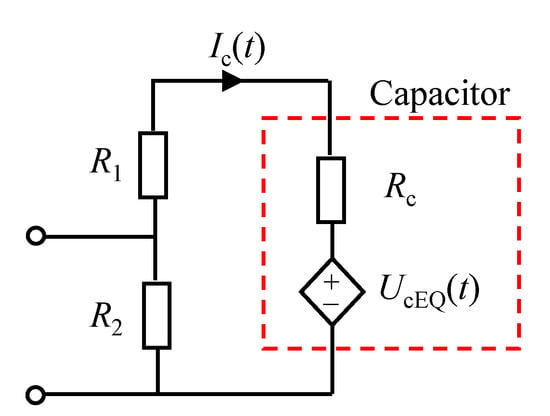 Figure 3. Detailed equivalent model (DEM) of each submodule of the MMC.The equivalent bridge voltage can be given bywhere i is the index of SM; N is the number of SM in each bridge arm; and, satisfiesMeanwhile,where is the number of SMs in on-state.The DEM provides a detailed representation of SMs switching events and individual capacitor ripples. It is feasible for arbitrary number of submodules. The DEM can be applied in order to design the balancing control of the capacitor voltages in the bridge arm. It can also represent the blocked mode, which is essential for accurately describing the MMC behaviors during startup and fault conditions [31,33].
 - EDM: because the capacitor discharge currents of SMs are the dominant components of the DC short-circuit current in DC power girds, MMCs are equivalent to a series RLC circuit in a EDM [13,34,35,36]. Figure 4 shows the structure of EDM.
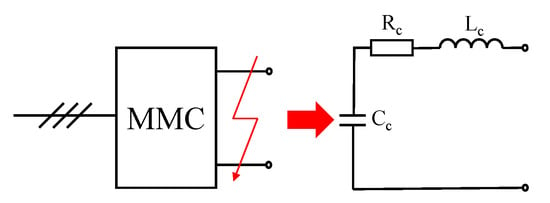 Figure 4. EDM of MMC under DC fault.The equivalent circuit parameters can be obtained from the detailed average model parameters, as follows.where and are the resistance and inductance of the bridge arms, respectively, is the sum of the on-state resistances of all SMs. The model that is given by (10) ignores the dynamics of MMC control systems, such as the power and voltage control [13,34], and it is suitable for DC short circuit current calculation [13,34,35,36].
The above-discussed models of MMC main circuit are presented in Table 3 in order to make a comparison of their features. In the table, √ indicates that the chosen technique is strongly related to the corresponding item; × indicates that the chosen technique is not related to the corresponding item.

Table 3.
Comparison of different MMC model.
3.2. MMC Control Systems
Figure 5 shows a typical structure of MMC control systems. The control systems for a single MMC consist of vector current controls (VCCs), phase-lock-loops (PLLs) and CCSCs [18,24,25,37,38]. The VCCs consist of inner and outer control loops. The control modes of MMCs are determined by the outer loop control objectives that can be chosen among active/reactive power control mode, DC voltage/reactive power control mode, active power/AC voltage control mode, and DC/AC voltage control mode.
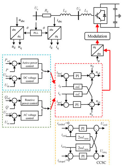
Figure 5.
Structure diagram of an MMC control system.
The VCC typically adopts d–q decoupling control strategy for power or voltage, with proportion-integral (PI) controllers. as shown in Figure 5. In VCC, the d–q decoupling control strategy is realized through four PI controllers. The outputs of the VCC are the dynamic phasors of the fundamental frequency components. Therefore, a fourth-order model can be formulated in order to illustrate the dynamics of PI controllers.
where , and are the reference values of active power P, reactive power Q, DC voltage , and AC voltage , respectively. The reference currents and are given below.
where and are the proportional constant and integral constant of the jth PI controller, repectively.
The outputs of the MMC control system denoted by and are the dynamic phasors of the fundamental frequency components in the d–q frame, as follows
PLL consists of two PI controllers. The dynamic of the PLL can be described as
where and are the parameters of the PLL; and are the intermediate control variables, which denote the integral of the PI controller’s error signals in PLL.
The output of the PLL is the phase signal park transforms, which can be expressed as
where is the angle frequency reference value of AC system and is the phase signal park transforms.
The CCSC contains two PI controllers, the dynamics of which can be expressed as
with and being the reference value of the circulating current. and indicate the intermediate control variables, which denote the integral of the PI controller’s error signals.
The output of the CCSC is the circulating current suppression voltage, which is denoted by and .
in which and are the proportional and integral gain of the PI controller in the CCSC.
3.3. AC System
Figure 6 depicts the equivalent circuit of an AC system, where the AC system is modelled by a resistance-inductance series circuit with an AC voltage source [39], and and are the equivalent AC resistance and inductance, respectively. are the transformer equivalent inductance. The internal dynamic characteristics of AC system are coupled with the DC power grid through the AC voltage source.

Figure 6.
Equivalent circuit of AC System.
3.4. DC System
The DC system of an MMC-based MTDC transmission system consists of DC transmission lines and the smoothing reactors at the converter ends [39]. With the smoothing reactors included in the equivalent series inductance of the transmission line, a lumped resistance-inductance series circuit is applied in order to establish the equivalent model of a DC transmission line, as shown in Figure 7.

Figure 7.
Equivalent circuit of DC Line.
The state space model of a DC transmission line can be given by
where and are the DC voltages at each end of the DC line; and, and are the equivalent resistance and inductance.
4. Analysis and Suppression Method of Short Circuit Current in MMC-Based MTDC Power Gird
The massive short circuit current caused by DC short circuit fault seriously threatens the security and reliability of DC power grids due to the small impedances of MMCs and DC transmission lines. It is necessary to analyze and suppress the DC short circuit currents in MMC-based MTDC power grid to ensure the safe and stable operation of DC power grid. A review of short current calculation and suppression methods is presented in this section.
4.1. Short Circuit Current Calculation Method
Various types of DC short circuit faults may occur in an MMC-based MTDC power grid, such as pole-to-pole short circuit fault and single-pole-to ground short-circuit fault. Existing research on DC short circuit current calculation mainly focuses on the pole-to-pole short circuit fault, because the pole-to-pole fault current of which is the most serious fault currents of all types of DC fault [13,34,35,36,40,41,42]. Therefore, the calculation of pole-to-pole short circuit current can provide guidance for parameter design and protection schemes of DC power grids.
4.1.1. Pole-to-Pole Short Circuit Current Calculation Method
Once a pole-to-pole DC short circuit fault occurs in MMC-based MTDC power grids, the capacitors discharge rapidly, which leads to massive short circuit current in both transmission lines and each MMC bridge arm. These phenomena usually happen within 5∼10 after the fault occurs [17,34]. For an MMC-based MTDC power grid, the dominant component of the short-circuit currents is the discharge currents of SM capacitors. The AC infeed contributions are exclusively present after 10 , which can be faithfully ignored [34,43]. It should be noted that the dynamics of MMCs that are based on various SM topologies under DC faults are developed in the same way before blocking, including HB-SM and other SM topologies with DC fault ride through capability [3,7,13].
An equivalent circuit method for calculating the pole-to-pole short circuit fault current in MMC-based MTDC power grids is presented in [13]. In the proposed calculation method, each MMC is represented by (10) and the DC line is equivalent to a series RLC circuit, as shown in Figure 8. The nodes that are connected to a real converter are defended as “real nodes” and the intersection nodes of the transmission lines without connection to a real converter are defined as “virtual node”.
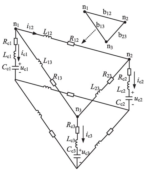
Figure 8.
Equivalent circuit of a three-terminal MMC-based DC power grid.
When considering a DC power grid with b branches, N real nodes, and M virtual nodes on the positive pole layer, the total number of the nodes is n. The branch currents matrix , node capacitor voltages matrix , and node injection current matrix can be expressed by
Branch current equations in matrix form can be expressed as
where is the incidence matrix with n nodes and b branches before fault. and is the resistance matrix and inductance matrix before fault, respectively. Assume the fault point that is indicated by 0 is set between node i and node j and is the fault resistance. By applying fault branch, the and are replaced by , and , . and denote the currents of branch and , respectively. The modified matrices are defined as and , respectively. is modified to with the branch that is replaced by branch and . Therefore, (20) can be rewritten as
The relationship between the post-fault branch currents and post-fault node injection currents can be represented by
where is the first to Nth columns in
The relationship between the capacitor voltages and currents can be presented by
where is given by
The virtual node voltages are not required and they can be eliminated through replacing the virtual node voltages with voltage drop through the DC line route from a node n to the short circuit fault point 0.
After eliminating the voltage of vertical nodes and update the matrices, the simultaneous differential equations for short circuit calculation are expressed as
where , , and are the updated matrices of , , and , respectively. The currents through the DC lines under the DC short circuit fault can be calculated through (25).
The proposed pole-to-pole short circuit current calculation method is available for both MMC and other VSCs. It is also available for calculating pole-to-pole short circuit current of different DC grid topologies, such as radial, ring, and mesh DC power grids. By dividing the DC power grid into fault zone and residual zone, this method is suitable for DC power grids with several DC voltage levels that are connected by DC/DC transformers. Only the internal fault zone current is needed to be calculated [13].
4.1.2. Short-Circuit Current Calculation Considering MMC Control
A short-circuit current calculation method that considers MMC control for MMC-based MTDC power grids is proposed in [40]. When compared with the previous calculation method in [13,35], the MMC is modeled as an RLC series circuit in parallel with a time-dependent controlled current source based on the AVM, as shown in Figure 9.
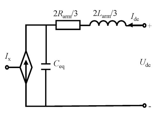
Figure 9.
DC side modified AVM of the MMC.
The equivalent model for an MMC-based MTDC power grid is established by combing the equivalent MMC model with the equivalent resistance-inductance series circuits of the DC lines. The post-fault branch currents and node voltages are obtained by solving the equivalent model of the DC grid through a companion circuit method. The proposed short circuit current calculation method that considers MMC control can be flexibly accommodated for all kinds of DC faults by updating the conductance matrix, history current vector, and DC current source vector [40].
The calculation of DC short circuit current calculation considering MMC control in [42] is performed in the frequency domain. The MMC is represented by an AVM and the effect of fault-generated traveling waves (FTWs) is fully considered. Therefore, the proposed method avoids the shortcoming that the line model-based methods cannot solve the nodal voltage, and the effective time window is much longer than the EDM-based method. The proposed method satisfies the accuracy requirement with a small computational burden. Therefore, it can be applied to a large number of fault calculations requirement scenes, such as parameter design and the protection of DC power grids.
When compared with the equivalent circuit method in [13,34] ignoring the MMC control, the short calculation proposed in [40,41,42] consider the dynamics of the control system in the short circuit current calculation, which can provide guidance for fault current suppression through MMC control.
4.2. DC Short Circuit Current Suppression Method in MMC-Based MTDC Power Grid
The existing short-circuit current suppression methods dealing with the DC short-circuit current can be divided into three types [13]:
- Using the MMC topology with DC fault ride through capability such as FB-SMs, CD-SMs, and 5LCC-SMs, etc.
- Installing current limiting device and cooperating with DC circuit breakers to isolate the DC fault line.
- Design MMC control strategies in order to suppress the short circuit current.
4.2.1. MMC Topologies with DC Fault Ride Through Capability
The HB-SM is the most widely applied topologies of MMC for DC power girds due to the simple structure and low cost. However, MMC rhat is based on HB-SM cannot block the fault currents fed from the AC grid [44], as shown in Figure 10a. Without DC CBs, it can only clear DC fault line by tripping the AC circuit breakers [45]. Various SMs have been proposed and investigated in order to improve fault-blocking performance of the MMC-based MTDC power grids [7]. Figure 10b–e show the short circuit current discharge circuit (in red line) for various SM topologies.
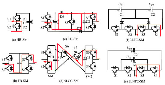
Figure 10.
Fault current discharge path of various SM topologies.
- FB circuit: after a DC short circuit current occurs, all of the IGBTs in the SMs are blocked and the capacitor voltages can generate reverse voltages to block the AC currents, as shown in Figure 10b. Thus, the FB-SMs can provide the DC fault ride through capability [17].
- CD circuit: in the CD based MMC-HVDC system, although the SMs can block the DC fault current [2], they can only generate a reverse voltage per bridge arm, which is, half of the reverse voltage produced by the FB-SMs per arm, as shown in Figure 10c. Thus, it takes more time for the CD-MMC to suppress the fault current to zero [16].
- 5LCC circuit: during a DC short circuit fault, the short-circuit current can be blocked by the two capacitors of the 5LCC-SM, as shown in Figure 10d. The reverse voltage generated by 5LCC-SM per arm is the same as the voltage produced by the FB-SM [17].
- 3LCC circuit: similar to the HB-SM, the three-level NPC and FC SMs cannot handle any DC fault, as shown in Figure 10e,f. Furthermore, from a manufacturing perspective, this solution is not very attractive [46].
The power transmission will be interrupted and the entire DC power grid will be shut down because SMs with DC fault ride through capability cut off the fault line through blocking all of the converters. Meanwhile, changing SM topologies will also create extra investment cost and additional loss of the project [2].
4.2.2. Fault Current Limiting Devices
Installing current limiting devices in DC systems and cutting off the fault line with DC CBs is another preferable suppression method for short circuit current. DC inductors and DC fault current limiters (FCLs) are two widely applied fault current limiting devices in MMC-based MTDC grids [47].
The current-limiting DC inductors are usually installed at both ends of the transmission lines in series in order to achieve better fault current suppression performance [48,49]. Figure 11 shows the short circuit current with different inductive fault current limiters in a four-terminal MMC-based power gird. The detailed structure and parameters of the four-terminal MMC-based power gird can be found in [50]. The inductive fault current limiters have a good performance in limiting the rising rate of the short circuit current.However, the series inductors can decrease the robustness and response speed of the DC system [51].
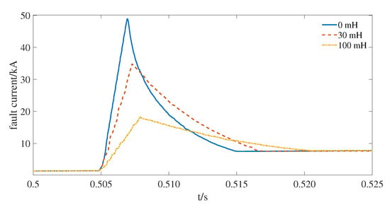
Figure 11.
Short circuit current with different inductive fault current limiters.
Another widely applied current limiting device is the DC FCL. FCL has many different topologies, such as resistive FCL, superconducting FCL (SFCL), solid state FCL, and magnetic FCL.
- Solid FCLs: solid FCLs are the most popular topologies due to its advantages of minimum power loss under normal condition, quick response, fast recovery capacity, good reliability, and low cost [52]. A resistive based solid-state FCL is proposed in [53]. The resistive based solid-state FCL consists of a current-limiting resistor module R and a control module in parallel, as shown in Figure 12.
 Figure 12. Operating states of resistive based solid-state fault current limiter (FCL).The resistive based solid-state FCL has two operational states. In the normal operating state, reverse parallel gate turns off thyristors (GTOS) in a conducting state, which ensures that the current-limiting resistor R is bypassed and the operational current can flow through the GTOs. Under DC fault conditions, and are turned off according to the operation signal issued by the fault detection system, and R is rapidly put into use, which increases the system damping and inhibits the fault current’s rising.
 - SFCL: the SFCL operates under a superconducting state in normal operation state, which offers no resistance to the load current. Meanwhile, it can achieve high resistance under fault conditions [50,54,55,56]. Figure 13 shows the short circuit current with resistive FCLs in a four-terminal MMC-based power grid, whose structure and parameters can be found in [50]. It can be found that, although the amplitude of the DC short circuit current can be effectively decreased, the resistive SFCL cannot limit the rising rate. To remedy this defect, reference [50] proposes an improved structure for inductive SFCL, as shown in Figure 14.
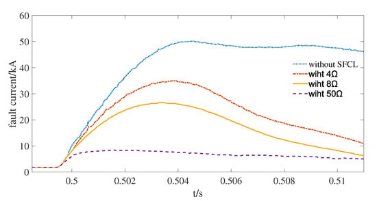 Figure 13. Short circuit current with the resistive FCLs.
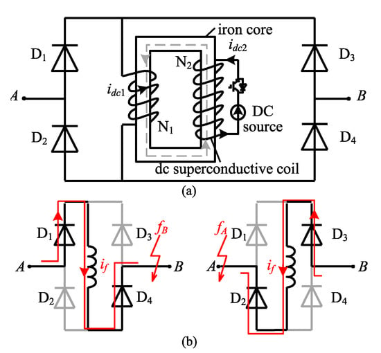 Figure 14. The working principle of the inductive SFCL: (a) Topology; (b) Short circuit current path.The inductive SFCL consists of several diodes and a saturated iron core SFCL. The saturated iron core SFCL is placed between the bridges composed with four diodes (). The proposed SFCL is connected in series in DC transmission lines via connectors A and B. Under normal conditions, the DC operational current can flow through the diodes groups and , or and . Wherever the short circuit fault occurs, the bi-directional SFCL allows for the fault current flow through. The copper made primary coils of the iron core SFCL are connected with the DC system. The secondary coils are made of superconductive materials and powered by a DC source. The external feature of the proposed inductive SFCL is equivalent to a small inductance and it has little impact on the system normal operational dynamics.The improved inductive SFCLs are applied to the four-terminal power grid that is shown in [50]. Under DC short circuit fault conditions, the inductance of the SFCL increases rapidly in order to restrain the rising rate of the short circuit current as shown in Figure 15. However, the permeability and the coil turns limit the size of the proposed inductive SFCL [50]. Moreover, superconductive FCL needs a high technological level and huge capital cost [47], which makes it unable to be widely applied in MMC-based MTDC power grids.
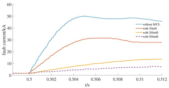 Figure 15. Short circuit current with the improved inductive SFCL.
 - NSFCL: a kind of structure of NSFCL, called capacitor-based FCL (CBFCL), is proposed in [57] and the power circuit structure of the CBFCL is shown Figure 16.
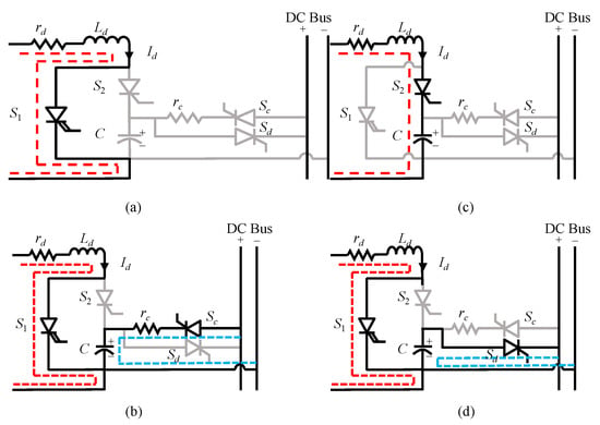 Figure 16. Performance of the proposed CBFCL: (a) under normal condition, (b) under normal condition considering charge of the capacitor bank, (c) under fault condition, and (d) after fault clearance.The CBFCL consists of three main sections:
- -
- isolation transformer and rectifier;
- -
- a bypass switch; and,
- -
- capacitor bank section with DC bus and corresponding switches.
Switch is applied to flow the normal operation current, while is applied to flow the fault current. Energy is transfered between the capacitor bank section and the DC bus through and . The operation modes that are under normal conditions are shown in Figure 16a,b and operation modes under fault conditions are shown in Figure 16c,d. Under normal conditions, is turened off and the capacitor bank section is charged while taking into account resistor in series with capacitor bank after a time constant. Because the capacitor bank section receives electrical energy from the DC bus, which leads to a voltage rise. is conducted after the voltage of capacitor bank section reached a determined level. The proposed CBFCL circuit has little impact on the normal operation of the MMC-HVDC system. When a DC short circuit fault occurs, is conducted. By turning on in short circuit current limitation, it makes the capacitor bank section and inductor participate insert in current path.
When comparing with previous studies, there are no switching strategies, such as pulse width modulation in the CBFCL for limiting the fault current and all of the switches behave like contactors in which they are closed or opened. This feature makes it possible to use cheaper switches and a better lifetime of switching instruments. Moreover, the CBFCL not only cuts off the short circuit current, but also saves energy in the capacitor that can be utilized after fault clearance [57].
4.2.3. MMC Fault Current Suppression Control Strategy
Although many researches have investigated the topologies and application of current limiting devices, it is still not a perfect method for suppressing the DC short-circuit current. Due to the difficulty in manufacturing and high cost, there is no suitable DC fault current limiting devices for widely application [58]. The full use of converters’ own capability through properly designed control strategies has become a prioritized choice, and it has been widely adopted in scenarios, such as DFIGs [59]. Therefore, making full use of the MMCs’ self-controlling ability will be an ideal and feasible method of short circuit current suppression for MMC-based MTDC power girds. Several researches have investigated the fault suppression method by designing new MMC control strategies [43,60].
Reference [60] proposed a comprehensive DC short-circuit fault ride through a strategy for a hybrid MMC with HB-SMs and FB-SMs. Under normal conditions, since the output voltage of the FB-SM is not required, the switches of the FB-SMs of both upper and lower arms are turned on. The circuit of the hybrid MMC is topologically equivalent to a traditional HB-MMC. Under a pole-to-pole fault condition, a bipolar output voltage of the FBSM is required in the upper and lower arm. The HB-SMs are bypassed and the circuit of the hybrid MMC is topologically equivalent to the double star-connected cascade H-bridge (CHB) converter that reduces the number of SM in operation and restrains the rise of short circuit current. The voltage injection method is applied to balance bridge arm capacitor energies, which ensures that the AC grid is not affected during the fault.
A source-side DC fault current clearance scheme for hybrid MMC-based power grids is proposed in [43]. The hybrid MMC consists of the HB-SMs and FB-SMs and it adopts converter DC current control and DC fault line current control during the fault. Figure 17 shows the flowchart of the protection scheme. After the DC short circuit fault is detected, the nearest MMC switches into fault line current control mode and the fault is isolated by a mechanical circuit breaker. In the proposed scheme, there are no DC CBs required, which significantly benefits the construction of MMC-based DC power grids. However, the above two methods need hybrid MMC and it is still not available for the most widely applied HB-MMC.
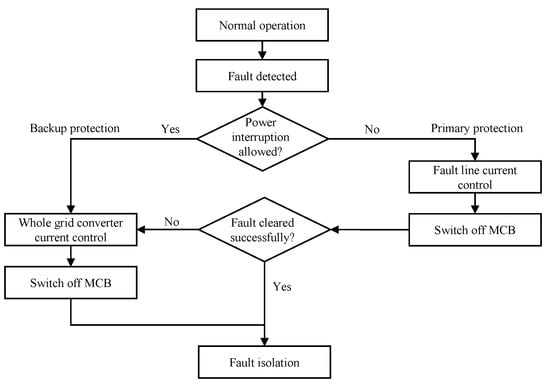
Figure 17.
Flowchart of the proposed protection schemes.
A DC short circuit current suppression method that is based on bridge arm voltage control is designed in [58]. It is found that the rising rate of the short circuit current is proportional to the number of sub-modules participating in the discharge that can be reduced through reducing the DC component in the reference voltage in the bridge arm after fault.
Figure 18 shows the fault current limiting control strategy structure. Under normal operation conditions, the output voltage of the system is larger than the voltage. The DC component compensation of the bridge arm voltage is 0, and the AC component in the bridge arm is not adjusted. Therefore, it has litle impact on the normal operation control characteristics of the system. Under DC fault conditions, the system output voltage rapidly drops once the short circuit fault occurs, which will be smaller than the voltage threshold. The control system switches the operation mode to compensate the DC component of the bridge arm voltage. With the DC and AC component of the compensated bridge arm reduced simultaneously, the output DC voltage is further reduced and the fault current is suppressed. The proposed current limiting measure is applied to a double-terminal MMC-HVDC system in [58]. Figure 19 shows the comparison of DC short circuit current with/without a current limiting measure. The increasing rate of the DC short-circuit current with a current limiting measure significantly decreases.
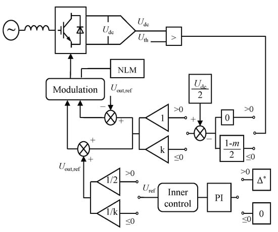
Figure 18.
Block diagram of MMC based on partial bypass of SMs.
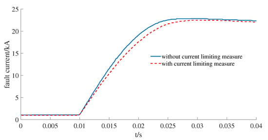
Figure 19.
Comparison of DC fault current with/without current limiting measure.
When compared with redesigning the MMC topologies and installing new current limiting devices, designing MMC control strategies for short-circuit current suppression can make full use of the control capability of MMCs and save capital cost.
5. Conclusions and Future Trend Exploration
This paper gave a comprehensive review of the existing DC short-circuit current analysis and suppression methods that were used in MMC-based MTDC power grids, including the latest theoretical achievements and techniques applied in engineering practice. The existing MMC modeling, DC short circuit current calculation methods, and suppression methods were classified and the advantages and disadvantages were summarized in this paper.
The models of MMC-based MTDC power grids have been studied and investigated for different scenarios. The DSM is feasible for SM-level dynamic analysis and control design. The AVM and SAVM are the preferred models for system-level analysis and control design. The DEM can be applied to design the balancing control of the capacitor voltages and represent the blocked mode. The EDM is the most suitable model for DC fault analysis and protection design.
The mainstream of DC short-circuit current calculation in MMC-based MTDC power grids is the equivalent circuit method, where MMCs are formulated as capacitor-inductor series circuits. However, the equivalent circuit method ignores the internal dynamics of MMCs and cannot display the inherent characteristics of the MMC-based MTDC power grids. It is necessary to establish the fault current analysis MMC model when considering the internal dynamics, and propose the short circuit calculation method considering the dynamic characteristics of MMC-based MTDC power grids.
The existing fault current suppression methods in MMC-based MTDC power grids usually include changing SM topologies, adding current limiting devices, and controlling the MMC. Table 4 presents the above-discussed DC short circuit current suppression methods to make a comparison of their features. In the table, √ indicates that the chosen technique is strongly related to the corresponding item; × indicates that the chosen technique is not related to the corresponding item; ’B’ indicates ’Big’; ’M’ indicates ’Moderate’; and, ’S’ indicates ’Small’. Most of the existing MMC-HVDC projects adopt HB-SMs and they cannot cut off the fault current by themselves. The cost of replacing the SM topologies with fault ride through capability is very large, and this disadvantage limits its practical application. Although installing fault current limiting devices can achieve good fault current suppression performance, it also has the disadvantages of high cost and impact on normal operational conditions. The future research direction of the fault current limiting devices is to reduce the cost and impact on the normal operational conditions. Suppressing the DC fault current through controlling MMC has the advantages of low cost, small impact on normal operational conditions, and flexibility in modification. Thus, it is an ideal DC fault current suppression method for MMC-based MTDC power grid and it has broad prospects for future development.

Table 4.
Comparison of different short circuit current suppression method.
Author Contributions
Conceptualization, B.Q.; methodology, B.Q., W.L., and R.Z.; software, W.L. and B.Q.; validation, W.L., J.L. and H.L.; investigation, W.L. and J.L.; writing—original draft preparation, B.Q., W.L. and R.Z.; writing—review and editing, W.L., R.Z., and J.L.; supervision, B.Q. All authors have read and agreed to the published version of the manuscript.
Funding
This work is funded by National Key R&D Program of China (2018YFB0904600) and Science, and technology project of State Grid Corporation of China (Control Strategy Optimization Technology for Large-Scale Photovoltaic Power Generation on the sending-end and receiving-end of DC power system).
Conflicts of Interest
The authors declare no conflict of interest.
References
- Shah, R.; Sánchez, J.C.; Preece, R.; Barnes, M. Stability and control of mixed AC–DC systems with VSC-HVDC: A review. IET Gener. Transm. Distrib. 2018, 12, 2207–2219. [Google Scholar] [CrossRef]
- Liu, G.; Xu, F.; Xu, Z.; Zhang, Z.; Tang, G. Assembly HVDC Breaker for HVDC Grids With Modular Multilevel Converters. IEEE Trans. Power Electron. 2017, 32, 931–941. [Google Scholar] [CrossRef]
- Debnath, S.; Qin, J.; Bahrani, B.; Saeedifard, M.; Barbosa, P. Operation, Control, and Applications of the Modular Multilevel Converter: A Review. IEEE Trans. Power Electron. 2015, 30, 37–53. [Google Scholar] [CrossRef]
- Qin, B.; Li, H.; Zhang, X.; Ding, T.; Ma, K.; Mei, S. Quantitative short-term voltage stability analysis of power systems integrated with DFIG-based wind farms. IET Gener. Transm. Distrib. 2020. [Google Scholar] [CrossRef]
- Ali, S.; Badar, J.; Akhter, F.; Bukhari, S.S.H.; Ro, J.-S. Real-Time Controller Design Test Bench for High-Voltage Direct Current Modular Multilevel Converters. Appl. Sci. 2020, 10, 6004. [Google Scholar] [CrossRef]
- An, T.; Tang, G.F.; Wang, W.N. Research and application on multiterminal and DC grids based on VSC-HVDC technology in China. High Volt. 2017, 2, 1–10. [Google Scholar] [CrossRef]
- Zhang, L.; Zou, Y.; Yu, J.; Qin, J.; Vittal, V.; Karady, G.G.; Shi, D.; Wang, Z. Modeling, control, and protection of modular multilevel converter-based multi-terminal HVDC systems: A review. CSEE J. Power Energy Syst. 2017, 3, 340–352. [Google Scholar] [CrossRef]
- Qin, B.; Li, H.; Zhou, X.; Li, J.; Liu, W. Low-Voltage Ride-Through Techniques in DFIG-BasedWind Turbines: A Review. Appl. Sci. 2020, 10, 2154. [Google Scholar] [CrossRef]
- Qin, B.; Ma, J.; Li, W.; Ding, T.; Sun, H.; Zomaya, A.Y. Decomposition-Based Stability Analysis for Isolated Power Systems With Reduced Conservativeness. IEEE Trans. Autom. Sci. Eng. 2020, 17, 1623–1632. [Google Scholar] [CrossRef]
- Wang, W.; Barnes, M. Power Flow Algorithms for Multi-Terminal VSC-HVDC With Droop Control. IEEE Trans. Power Syst. 2014, 29, 1721–1730. [Google Scholar] [CrossRef]
- Prieto-Araujo, E.; Bianchi, F.D.; Junyent-Ferre, A.; Gomis-Bellmunt, O. Methodology for Droop Control Dynamic Analysis of Multi-terminal VSC-HVDC Grids for Offshore Wind Farms. IEEE Trans. Power Deliv. 2011, 26, 2476–2485. [Google Scholar] [CrossRef]
- Thams, F.; Eriksson, R.; Molinas, M. Interaction of Droop Control Structures and Its Inherent Effect on the Power Transfer Limits in Multi-terminal VSC-HVDC. IEEE Trans. Power Deliv. 2017, 32, 182–192. [Google Scholar] [CrossRef]
- Li, C.; Zhao, C.; Xu, J.; Ji, Y.; Zhang, F.; An, T. A Pole-to-Pole Short-Circuit Fault Current Calculation Method for DC Grids. IEEE Trans. Power Syst. 2017, 32, 4943–4953. [Google Scholar] [CrossRef]
- Eriksson, R.; Beerten, J.; Ghandhari, M.; Belmans, R. Optimizing DC Voltage Droop Settings for AC/DC System Interactions. IEEE Trans. Power Deliv. 2014, 29, 362–369. [Google Scholar] [CrossRef]
- Franck, C.M. HVDC Circuit Breakers: A Review Identifying Future Research Needs. IEEE Trans. Power Deliv. 2011, 26, 998–1007. [Google Scholar] [CrossRef]
- Marquardt, R. Modular multilevel converter: An universal concept for HVDC-networks and extended DC-bus-applications. In Proceedings of the 2010 International Power Electronics Conference-ECCE ASIA, Sapporo, Japan, 21–24 June 2010; pp. 502–507. [Google Scholar]
- Qin, J.; Saeedifard, M.; Rockhill, A.; Zhou, R. Hybrid Design of Modular Multilevel Converters for HVDC Systems Based on Various Submodule Circuits. IEEE Trans. Power Deliv. 2015, 30, 385–394. [Google Scholar] [CrossRef]
- Li, T.; Gole, A.M.; Zhao, C. Harmonic Instability in MMC-HVDC Converters Resulting from Internal Dynamics. IEEE Trans. Power Deliv. 2016, 31, 1738–1747. [Google Scholar] [CrossRef]
- Meng, X.; Han, J.; Pfannschmidt, J.; Wang, L.; Li, W.; Zhang, F.; Belanger, J. Combining Detailed Equivalent Model With Switching-Function-Based Average Value Model for Fast and Accurate Simulation of MMCs. IEEE Trans. Energy Convers. 2020, 35, 484–496. [Google Scholar] [CrossRef]
- Guo, D.; Rahman, M.H.; Ased, G.P.; Xu, L.; Emheme, A.; Burt, G.M.; Audichya, Y. Detailed quantitative comparison of half-bridge modular multilevel converter modelling methods. J. Eng. 2019, 2019, 1292–1298. [Google Scholar] [CrossRef]
- Song, Q.; Liu, W.; Li, X.; Rao, H.; Xu, S.; Li, L. A Steady-State Analysis Method for a Modular Multilevel Converter. IEEE Trans. Power Electron. 2013, 28, 3702–3713. [Google Scholar] [CrossRef]
- Xu, J.; Gole, A.M.; Zhao, C. The Use of Averaged-Value Model of Modular Multilevel Converter in DC Grid. IEEE Trans. Power Deliv. 2015, 30, 519–528. [Google Scholar] [CrossRef]
- Saad, H.; Dennetière, S.; Mahseredjian, J.; Delarue, P.; Guillaud, X.; Peralta, J.; Nguefeu, S. Modular Multilevel Converter Models for Electromagnetic Transients. IEEE Trans. Power Deliv. 2014, 29, 1481–1489. [Google Scholar] [CrossRef]
- Guo, C.; Yang, J.; Zhao, C. Investigation of Small-Signal Dynamics of Modular Multilevel Converter Under Unbalanced Grid Conditions. IEEE Trans. Ind. Electron. 2019, 66, 2269–2279. [Google Scholar] [CrossRef]
- Guo, C.; Liu, W.; Zhao, J.; Zhao, C. Impact of control system on small-signal stability of hybrid multi-infeed HVDC system. IET Gener. Transm. Distrib. 2018, 12, 4233–4239. [Google Scholar] [CrossRef]
- Peralta, J.; Saad, H.; Dennetiere, S.; Mahseredjian, J.; Nguefeu, S. Detailed and Averaged Models for a 401-Level MMC–HVDC System. IEEE Trans. Power Deliv. 2012, 27, 1501–1508. [Google Scholar] [CrossRef]
- Saad, H.; Peralta, J.; Dennetière, S.; Mahseredjian, J. Dynamic Averaged and Simplified Models for MMC-Based HVDC Transmission Systems. IEEE Trans. Power Deliv. 2013, 2013 28, 1723–1730. [Google Scholar] [CrossRef]
- Liu, S.; Xu, Z.; Hua, W.; Tang, G.; Xue, Y. Electromechanical Transient Modeling of Modular Multilevel Converter Based Multi-Terminal HVDC Systems. IEEE Trans. Power Syst. 2014, 29, 72–83. [Google Scholar] [CrossRef]
- Boyu, Q.; Wansong, L.; Ruowei, Z.; Tao, D.; Jialing, L. Small-signal stability analysis and optimal control parameters design of MMC-based MTDC transmission systems. IET Gener. Transm. Distrib. 2020. [Google Scholar] [CrossRef]
- Yu, S.; Zhang, S.; Wei, Y.; Zhu, Y.; Sun, Y. Efficient and accurate hybrid model of modular multilevel converters for large MTDC systems. IET Gener. Transm. Distrib. 2018, 12, 1565–1572. [Google Scholar] [CrossRef]
- Gnanarathna, U.N.; Gole, A.M.; Jayasinghe, R.P. Efficient Modeling of Modular Multilevel HVDC Converters (MMC) on Electromagnetic Transient Simulation Programs. IEEE Trans. Power Deliv. 2011, 26, 316–324. [Google Scholar] [CrossRef]
- Ajaei, F.B.; Iravani, R. Enhanced Equivalent Model of the Modular Multilevel Converter. IEEE Trans. Power Deliv. 2015, 30, 666–673. [Google Scholar] [CrossRef]
- Wang, S.; Alsokhiry, F.S.; Adam, G.P. Impact of Submodule Faults on the Performance of Modular Multilevel Converters. Energies 2020, 13, 4089. [Google Scholar] [CrossRef]
- Bucher, M.K.; Franck, C.M. Contribution of Fault Current Sources in Multiterminal HVDC Cable Networks. IEEE Trans. Power Deliv. 2013, 28, 1796–1803. [Google Scholar] [CrossRef]
- Xu, J.; Zhu, S.; Li, C.; Zhao, C. The Enhanced DC Fault Current Calculation Method of MMC-HVDC Grid with FCLs. IEEE J. Emerg. Sel. Top. Power Electron. 2019, 7, 1758–1767. [Google Scholar] [CrossRef]
- Ye, H.; Gao, S.; Li, G.; Liu, Y. Efficient Estimation and Characteristic Analysis of Short-Circuit Currents for MMC-MTDC Grids. IEEE Trans. Ind. Electron. 2020. [Google Scholar] [CrossRef]
- Wang, Y.; Zhao, C.; Guo, C.; Rehman, A.U. Dynamics and small signal stability analysis of PMSG-based wind farm with an MMC-HVDC system. CSEE J. Power Energy Syst. 2020, 6, 226–235. [Google Scholar]
- Ji, K.; Tang, G.; Yang, J.; Li, Y.; Liu, D. Harmonic Stability Analysis of MMC-Based DC System Using DC Impedance Model. IEEE J. Emerg. Sel. Top. Power Electron. 2020, 8, 1152–1163. [Google Scholar] [CrossRef]
- Daryabak, M.; Filizadeh, S.; Jatskevich, J.; Davoudi, A.; Cano, J.; Mehrizi-Sani, A. Modeling of LCC-HVDC Systems Using Dynamic Phasors. IEEE Trans. Power Deliv. 2014, 29, 1989–1998. [Google Scholar] [CrossRef]
- Gao, S.; Ye, H.; Liu, Y. Accurate and Efficient Estimation of Short-Circuit Current for MTDC Grids Considering MMC Control. IEEE Trans. Power Deliv. 2020, 35, 1541–1552. [Google Scholar] [CrossRef]
- Langwasser, M.; Carne, G.D.; Liserre, M.; Biskoping, M. Improved Fault Current Calculation Method for Pole-to-Pole Faults in MMC Multi-Terminal HVDC Grids Considering Control Dynamics. In Proceedings of the 2018 IEEE Energy Conversion Congress and Exposition (ECCE), Portland, OR, USA, 23–27 September 2018. [Google Scholar]
- Guo, Y.; Li, H.; Liang, Y.; Wang, G. A Method to Calculate Short-Circuit Faults in High-Voltage DC Grids. IEEE Trans. Power Deliv. 2020. [Google Scholar] [CrossRef]
- Xu, J.; Zhao, X.; Jing, H.; Liang, J.; Zhao, C. DC Fault Current Clearance at the Source Side of HVDC Grid Using Hybrid MMC. IEEE Trans. Power Deliv. 2020, 35, 140–149. [Google Scholar] [CrossRef]
- Vidal-Albalate, R.; Forner, J. Modeling and Enhanced Control of Hybrid Full Bridge–Half Bridge MMCs for HVDC Grid Studies. Energies 2020, 13, 180. [Google Scholar] [CrossRef]
- Tang, G.; Xu, Z.; Zhou, Y. Impacts of Three MMC-HVDC Configurations on AC System Stability Under DC Line Faults. IEEE Trans. Power Syst. 2014, 29, 3030–3040. [Google Scholar] [CrossRef]
- Solas, E.; Abad, G.; Barrena, J.A.; Aurtenetxea, S.; Cárcar, A.; Zając, L. Modular Multilevel Converter With Different Submodule Concepts—Part I: Capacitor Voltage Balancing Method. IEEE Trans. Ind. Electron. 2013, 60, 4525–4535. [Google Scholar] [CrossRef]
- Huang, Q.; Zou, G.; Sun, W.; Xu, C. Fault current limiter for the MMC-based multi-terminal DC grids. IET Gener. Transm. Distrib. 2020, 14, 3269–3277. [Google Scholar] [CrossRef]
- Rao, H. Architecture of Nan’ao multi-terminal VSC-HVDC system and its multi-functional control. CSEE J. Power Energy Syst. 2015, 1, 9–18. [Google Scholar] [CrossRef]
- Liu, K.; Huai, Q.; Qin, L.; Zhu, S.; Liao, X.; Li, Y.; Ding, H. Enhanced Fault Current-Limiting Circuit Design for a DC Fault in a Modular Multilevel Converter-Based High-Voltage Direct Current System. Appl. Sci. 2019, 9, 1661. [Google Scholar] [CrossRef]
- Wang, C.; Li, B.; He, J.; Xin, Y. Design and Application of the SFCL in the Modular Multilevel Converter Based DC System. IEEE Trans. Appl. Supercond. 2017, 27, 1–4. [Google Scholar] [CrossRef]
- Wang, S.; Li, C.; Adeuyi, O.D.; Li, G.; Ugalde-Loo, C.E.; Liang, J. Coordination of MMCs With Hybrid DC Circuit Breakers for HVDC Grid Protection. IEEE Trans. Power Deliv. 2019, 2019 34, 11–22. [Google Scholar] [CrossRef]
- Ghanbari, T.; Farjah, E.; Zandnia, A. Development of a high-performance bridge-type fault current limiter. IET Gener. Transm. Distrib. 2014, 8, 486–494. [Google Scholar] [CrossRef]
- Sujuan, X.; Yufeng, Q.; Tianshu, B. Resistive DC fault current limiter. J. Eng. 2017, 2017, 1682–1685. [Google Scholar] [CrossRef]
- Jiang, Z.; Wang, Y.; Dai, S.; Ma, T.; Yuan, X.; Liu, M.; Chen, H.; Wang, M.; Peng, C. Application and Design of Resistive SFCL in pm160 kV MMC-HVdc System. IEEE Trans. Appl. Supercond. 2019, 29, 1–5. [Google Scholar]
- Li, B.; He, J. Studies on the Application of R-SFCL in the VSC-Based DC Distribution System. IEEE Trans. Appl. Supercond. 2016, 26, 1–5. [Google Scholar] [CrossRef]
- Khan, U.A.; Lee, J.; Amir, F.; Lee, B. A Novel Model of HVDC Hybrid-Type Superconducting Circuit Breaker and Its Performance Analysis for Limiting and Breaking DC Fault Currents. IEEE Trans. Appl. Supercond. 2015, 25, 1–9. [Google Scholar] [CrossRef]
- Nourmohamadi, H.; Nazari-Heris, M.; Sabahi, M.; Abapour, M. A Novel Structure for Bridge-Type Fault Current Limiter: Capacitor-Based Nonsuperconducting FCL. IEEE Trans. Power Electron. 2018, 33, 3044–3051. [Google Scholar] [CrossRef]
- Xin, Y.; Yang, Y.; Wang, W.; Wang, T.; Xu, G.; Dong, Q. Current Suppresvsion Method for DC Side Short Circuit Fault of MMC. In Proceedings of the 4th IEEE Workshop on the Electronic Grid (eGRID), Xiamen, China, 11–14 November 2019; pp. 1–8. [Google Scholar]
- Qin, B.; Sun, H.; Ma, J.; Li, W.; Ding, T.; Wang, Z.; Zomaya, A.Y. Robust H∞ Control of Doubly Fed Wind Generator Via State-Dependent Riccati Equation Technique. IEEE Trans. Power Syst. 2019, 34, 2390–2400. [Google Scholar] [CrossRef]
- Cui, S.; Sul, S. A Comprehensive DC Short-Circuit Fault Ride through Strategy of Hybrid Modular Multilevel Converters (MMCs) for Overhead Line Transmission. IEEE Trans. Power Electron. 2016, 31, 7780–7796. [Google Scholar] [CrossRef]
© 2020 by the authors. Licensee MDPI, Basel, Switzerland. This article is an open access article distributed under the terms and conditions of the Creative Commons Attribution (CC BY) license (http://creativecommons.org/licenses/by/4.0/).