Article

Magnetic Abrasive Finishing of Beta-Titanium Wire Using Multiple Transfer Movement Method

1
Department of Mechanical Design Engineering, Jeonbuk National University, 567, Baekje-daero, Deokjin-gu, Jeonju-si, Jeollabuk-do 54896, Korea
2
Department of Energy Storage/Conversion Engineering of Graduate School, Jeonbuk National University, Jeonju, Jeollabuk-do 54896, Korea
*
Author to whom correspondence should be addressed.
Appl. Sci. 2020, 10(19), 6729; https://doi.org/10.3390/app10196729
Submission received: 25 August 2020 / Revised: 21 September 2020 / Accepted: 22 September 2020 / Published: 25 September 2020
(This article belongs to the Special Issue Active Materials for Medical Applications)

Abstract

:
Titanium is often used in various important applications in transportation and the healthcare industry. The goal of this study was to determine the optimum processing of magnetic abrasives in beta-titanium wire, which is often used in frames for eyeglasses because of its excellent elasticity among titanium alloys. To check the performance of the magnetic abrasive finishing process, the surface roughness (Ra) was measured when the specimen was machined at various rotational speeds (700, 1500, and 2000 rpm) in the presence of diamond paste of various particle sizes (0.5, 1, and 3 μm). We concluded that the surface roughness (Ra) was the best at 2000 rpm, 1 μm particle size, and 300 s processing time, and the surface roughness of β-titanium improved from 0.32 to 0.05 μm. In addition, the optimal conditions were used to test the influence of the finishing gap, and it was found that the processing power was superior at a gap of 3 mm than at 5 mm when processing was conducted for 300 s.

1. Introduction

Materials with good mechanical properties are needed in high-tech applications. Therefore, many studies are being conducted to achieve high accuracy and improve the quality of products, particularly with regard to surface properties. Many machining methods have been adopted for high-precision processing technology [1,2]. However, the surface accuracy results obtained are not satisfactory in many industries. Wire titanium comes in the form of pure titanium alloy, which has been widely used in eyeglasses frames because of its good elasticity, resilience, and ability to bend to fit the shape of the face. Beta titanium is lighter than regular titanium and can be a good alternative material for weight reduction because it is stronger, resistant to heat, and shows less deformation and deterioration caused by salt [3]. Thus, it has been applied in clinical situations, for example, in braces for teeth. However, beta-titanium alloy is difficult to machine due to its low thermal conductivity. The magnetic abrasive finishing (MAF) process is an ultra-precision machining technique which uses magnetic fields to process hard-to-work pieces [4,5,6]. Heng et al. [7] applied the magnetic abrasive finishing process to achieve a high surface quality of magnesium alloy bar (Ø3 mm × 50 mm). His result showed that the value of surface roughness was reduced 0.02 µm after the finishing process within 20 s. Chang et al. [8] used the magnetic abrasive finishing process for cylindrical surface finishing of SKD11 steel material (Ø15 mm × 80 mm). His result showed that after the finishing process, the best surface roughness (Ra) of 0.042 μm was achieved by 180 μm steel grit abrasive.
However, workpieces made of small diameter beta-titanium alloy wire may experience fractures and micro-cracks due to the high pressure of the magnetic abrasive finishing process [9,10,11,12]. Therefore, the magnetic abrasive finishing process must be employed with new processing parameters such as a wire moving system (WMS), a wire vibration system (WVS), or a combination of WMS and WVS.
We conducted a study to identify the optimal conditions for beta-titanium workpieces using a magnetic abrasive finishing process with multiple transfer movement methods. The experiments were carried out with various abrasive particle sizes, rotational speeds, finishing gaps, and multiple transport motion methods under the chosen processing conditions.

2. Experimental Equipment and Methods

2.1. Experimental Equipment

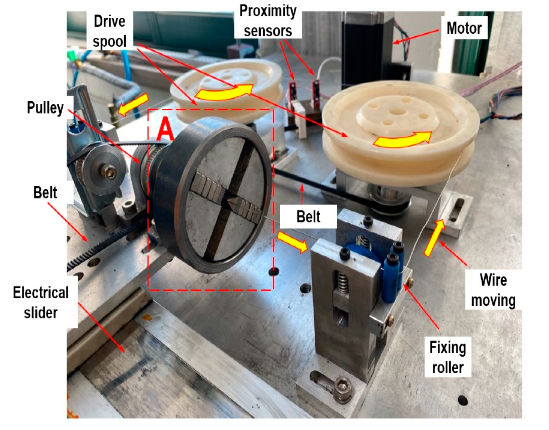
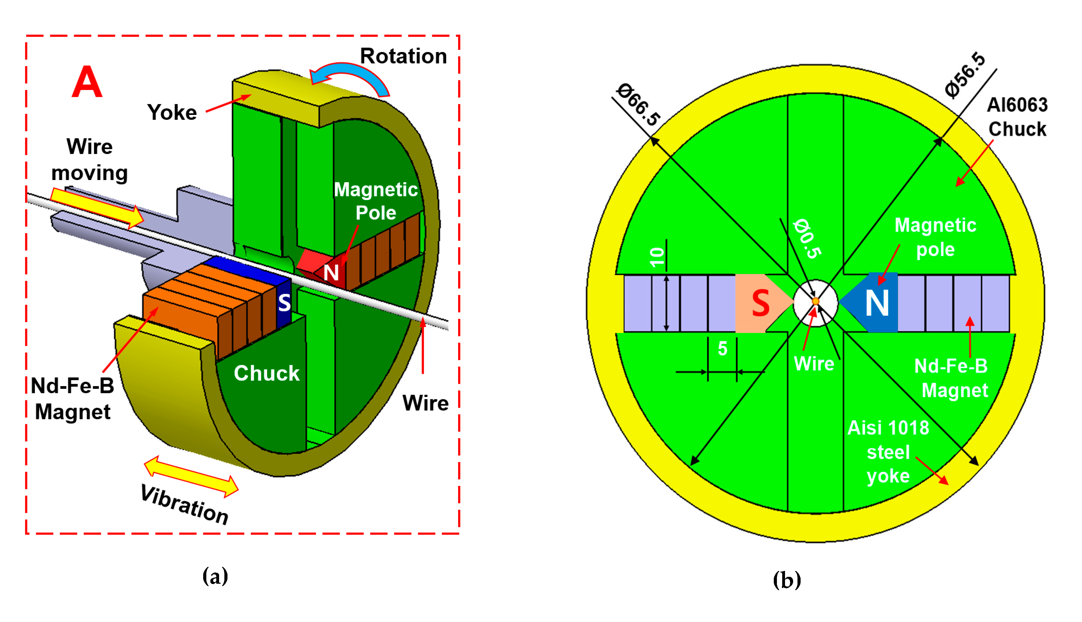
Figure 1 and Figure 2 show the experimental setups of the magnetic abrasive finishing process and the finishing equipment for beta-titanium wire alloys, respectively. The magnetic abrasive finishing (MAF) equipment uses a rotational magnetic field and consists of a stepping motor and a system controller. These allow forward rotation and reverse rotation with ultra-high precision to improve the surface accuracy of machined beta-titanium alloy. This equipment was designed to allow the wire workpieces to reciprocate inside a flexible magnetic abrasive brush. MAF equipment for beta-titanium wire alloy processing is divided into three main parts: (i) the wire moving system (WMS), (ii) the rotational magnetic field system (RMS), and (iii) the wire vibration system (WVS). First, the wire moving system (WMS) consists of two sensors and a drive spool, stepping motor, belt, and power supply. The WMS reciprocates wires left and right inside the rotational magnetic field. Secondly, the RMS system consists of a belt, rpm controller, pulley, (Nd-Fe-B) permanent magnet, steel yoke, steel chuck, belt, program controller, stepping motor, and the unbonded magnetic abrasive materials. Permanent magnets (Nd-Fe-B) are used because they are small in volume and can generate high magnetic flux density, which can improve the resulting surface roughness [13,14,15,16]. Finally, the wire vibration system (WVS) consists of an electronic slider, a power supply, and a programmable controller. This method generates vibration in a rotational magnetic field of 8 Hz with 2 mm amplitude. The vibration of the magnetic field rotating system is used for increasing the number of finishing times, allowing the magnetic smoothing to proceed efficiently on the workpiece surface. The specimen used in this study is β-titanium wire with a diameter of 0.5 mm and a length of 50 mm. Figure 3 shows a schematic view of the device used to generate a rotational magnetic field for processing beta-titanium wire. Figure 3a shows the 3D view of rotational magnetic field device. Figure 3b shows the 2D dimensional view of the rotational magnetic field device used in this experiment. The finishing device consists of two sets of Nd-Fe-B magnets (20 mm × 10 mm × 5 mm), Al 6063 chuck, AISI 1018 steel yoke, and two sharp edges of AISI 1018 steel magnetic poles.

2.2. Beta-Titanium Wire Material

Compared with stainless steel wires, beta-titanium wire material has lower force magnitudes, lower elastic modulus, higher spring back (maximum elastic deflection), lower yield strength, and good ductility, weldability, and corrosion resistance. Its formability and weldability are advantages over Ni-Ti alloys [17]. Due to its excellent mechanical properties, it has been used in medical applications, sport applications, and as frames for eyeglasses. Therefore, beta-titanium wire material was used in this study as the workpiece with a diameter of 0.5 mm and a length of 50 mm. The chemical composition and mechanical properties of the specimen are shown in Table 1 and Table 2.

2.3. Experimental Methods

The experimental conditions are as shown in Table 3. The beta-titanium wire workpiece was 0.5 mm in diameter, 50 mm in length, and 0.33 μm Ra in surface roughness. Unbonded magnetic abrasive material was used in this study, which is a mixture of electrolytic iron powder (1.2 g, Fe #200), diamond paste (0.6 g), carbon powder (0.02 g), and light oil (0.3 mL). To find the optimal conditions for processing, we studied three sample β-titanium wire rotation speeds (700, 1500, 2000 rpm) and three diamond particle sizes (0.5, 1, and 3 μm). The process was conducted for 300 s of total finishing time at each condition. Ultrasonic cleaning and drying were performed every 60 s of finishing time to allow measurement of the correct surface roughness (Ra) of the β-titanium wire workpiece. In addition, the optimal conditions obtained from the previous two experiments (i.e., rotation speed, abrasive particle size) were applied with different finishing gaps (3 and 5 mm). The distribution of magnetic flux density was analyzed using a finite element method magnet (FEMM). To understand the change of surface roughness after the finishing process, the average surface roughness (Ra) values were measured every 60 s; three times at different positions by a surface roughness tester (Mitutoyo SJ-400, Japan).

3. Experimental Results and Analysis

3.1. Influence of Particle Size

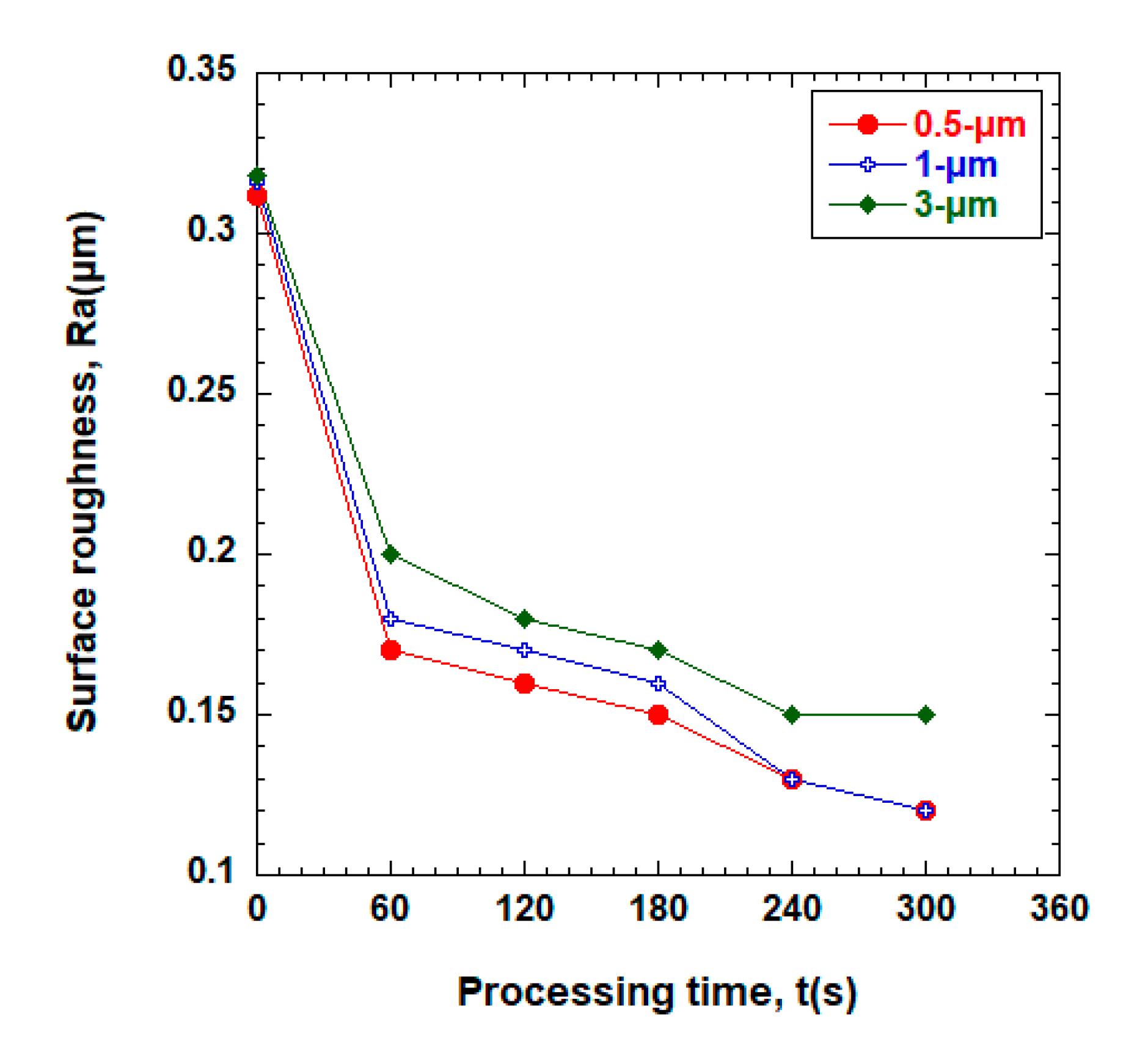
Figure 4 shows the changes in surface roughness (Ra) as a function of finishing time for various magnetic abrasive particle sizes. To determine the effect of changes in magnetic abrasive particle sizes (0.5, 1, 3 μm) we performed experiments with an 8 Hz vibration rotational magnetic field at a rotational speed of 1500 rpm. The smallest (0.5 μm) grain size abrasive material was found to have the best effect followed by 1 and 3 μm magnetic abrasive particles. After the finishing process, the surface roughness of the workpieces were 0.12, 0.12, and 0.15 μm for particle sizes of 0.5, 1, and 3 μm, respectively. Thus, smaller magnetic abrasive grain sizes produced better results in terms of the surface roughness.

3.2. Influence of Rotational Speed

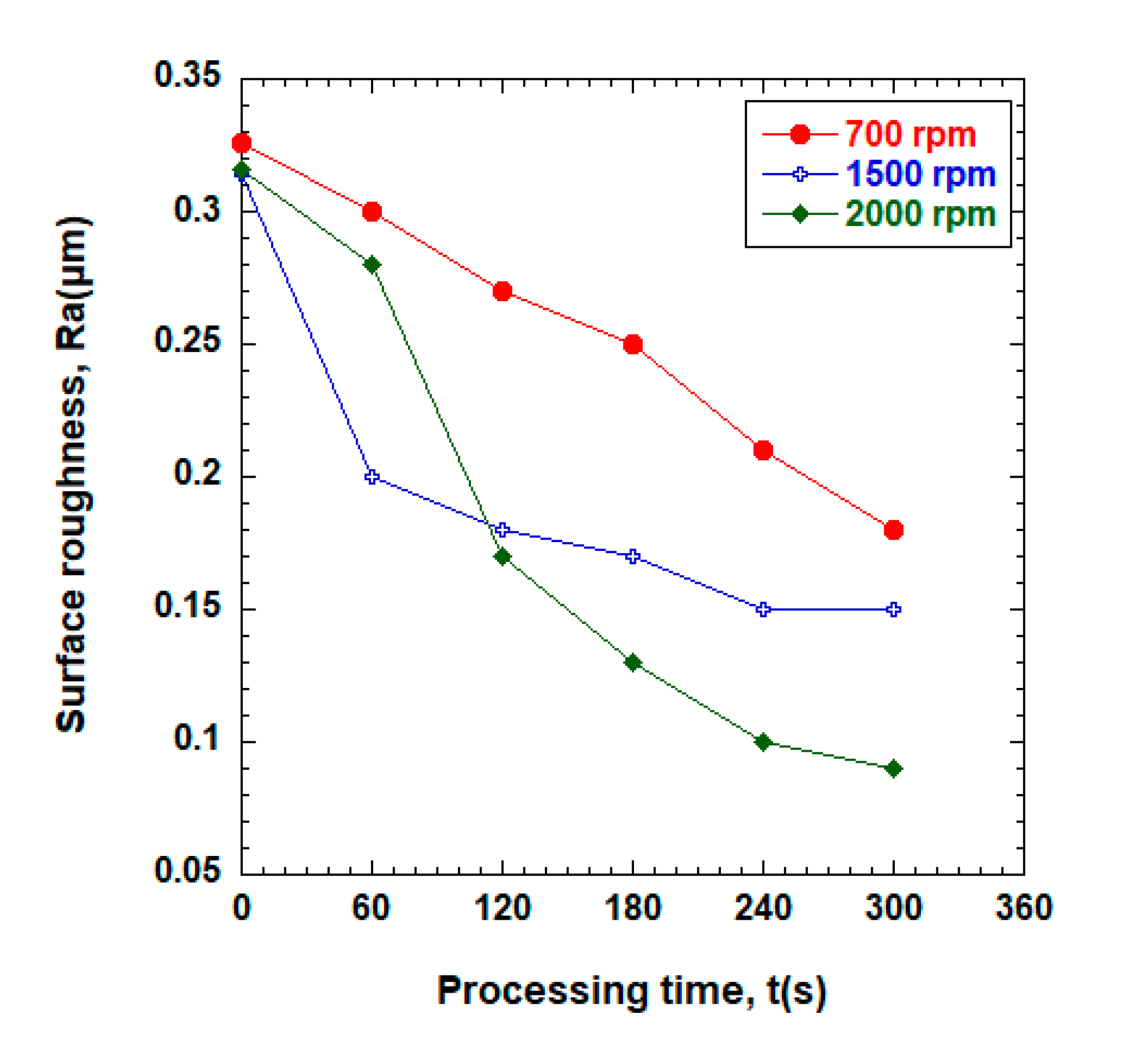
To determine the optimum finishing performance as a function of the rotational speed of the workpiece, three rotational speeds were investigated: 700, 1500, and 2000 rpm. For these experiments, the particle size was 1 μm and the magnetic pole shape was a sharp edge. Figure 5 shows the changes in surface roughness (Ra) according to different rotational speeds. The results showed that all the surface roughness values continually improved from 0 s to 300 s of finishing time. The surface roughness (Ra) was improved to 0.18, 0.15, and 0.09 μm at 700, 1500, and 2000 rpm, respectively. Thus, we confirmed that increasing the rotational speed improved the surface roughness (Ra) of the wire workpiece. This can be explained by the fact that increasing the rotational speed of the magnetic field can increase the relative motion between the workpiece surface and magnetic abrasive particles.

3.3. Influence of Clearance Distance

To determine the optimum clearance distance of the workpiece, the magnetic field distribution at the finishing zone was measured using an FEMM. In addition, the chemical composition of beta-titanium wire was analyzed by EDS and the density was verified by mapping. Before the finishing process, the clearance distances between the two magnetic poles were set to 3 and 5 mm. Figure 6 shows the result of the FEMM analysis; the results obtained at the finishing zone were 2.82347 magnetic flux density (T) for 3 mm clearance and 2.56956 T for 5 mm clearance. Figure 7 shows the relationship between magnetic flux density (T) and distance from the magnetic pole. Figure 8 shows the changes in surface roughness (Ra) and processing time for different finishing gaps. The finishing conditions were conducted under the optimal conditions (rotation: 2000 rpm; abrasive: 1 μm; sharp-edged magnetic pole, total finishing time: 300 s). The results showed that surface roughness continually improved from 0 s to 300 s of finishing time. The surface roughness (Ra) improved to 0.08 μm for a gap of 3 mm and 0.21 μm for a gap of 5 mm. This showed that the 3 mm finishing gap was much better than a 5 mm gap. Thus, a smaller finishing gap distance can provide better surface roughness (Ra) on the beta-titanium wire workpiece. According to Figure 6, a higher magnetic flux density was obtained when using smaller finishing gaps. During the finishing process, the higher magnetic flux density generated higher magnetic force, which acted strongly on the magnetic abrasive particles, resulting in a workpiece with better surface quality.
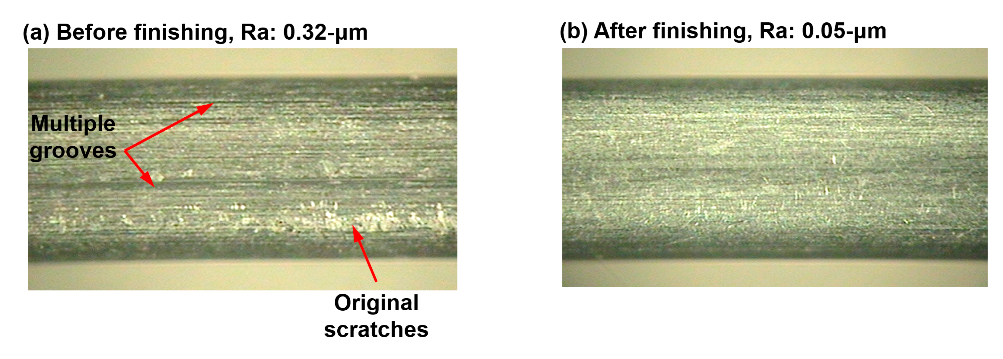
The surface conditions of beta-titanium wire before and after finishing were investigated using an optical microscope (IMS-M-345) (see Figure 9). Figure 9a shows the initial surface condition before the finishing process. As shown in Figure 9a, the multiple grooves and original scratches can be found everywhere on the initial surface and surface roughness Ra is 0.32 μm. Figure 9b shows the surface condition after the finishing process. From Figure 9b, the surface condition of beta-titanium wire is smoother than the initial surface condition and the multiple grooves were mostly removed. A surface roughness (Ra) after the finishing process is 0.05 μm.
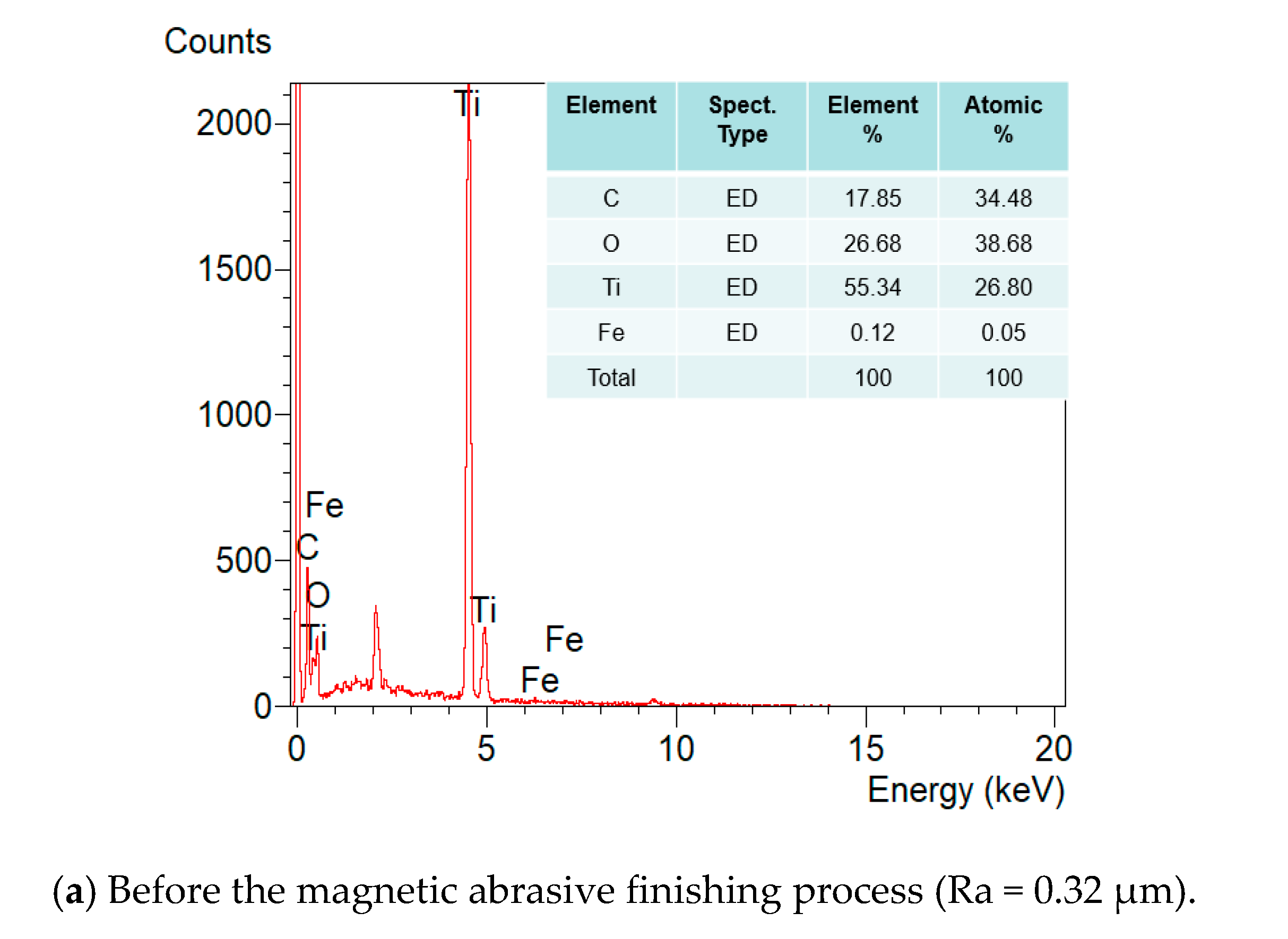
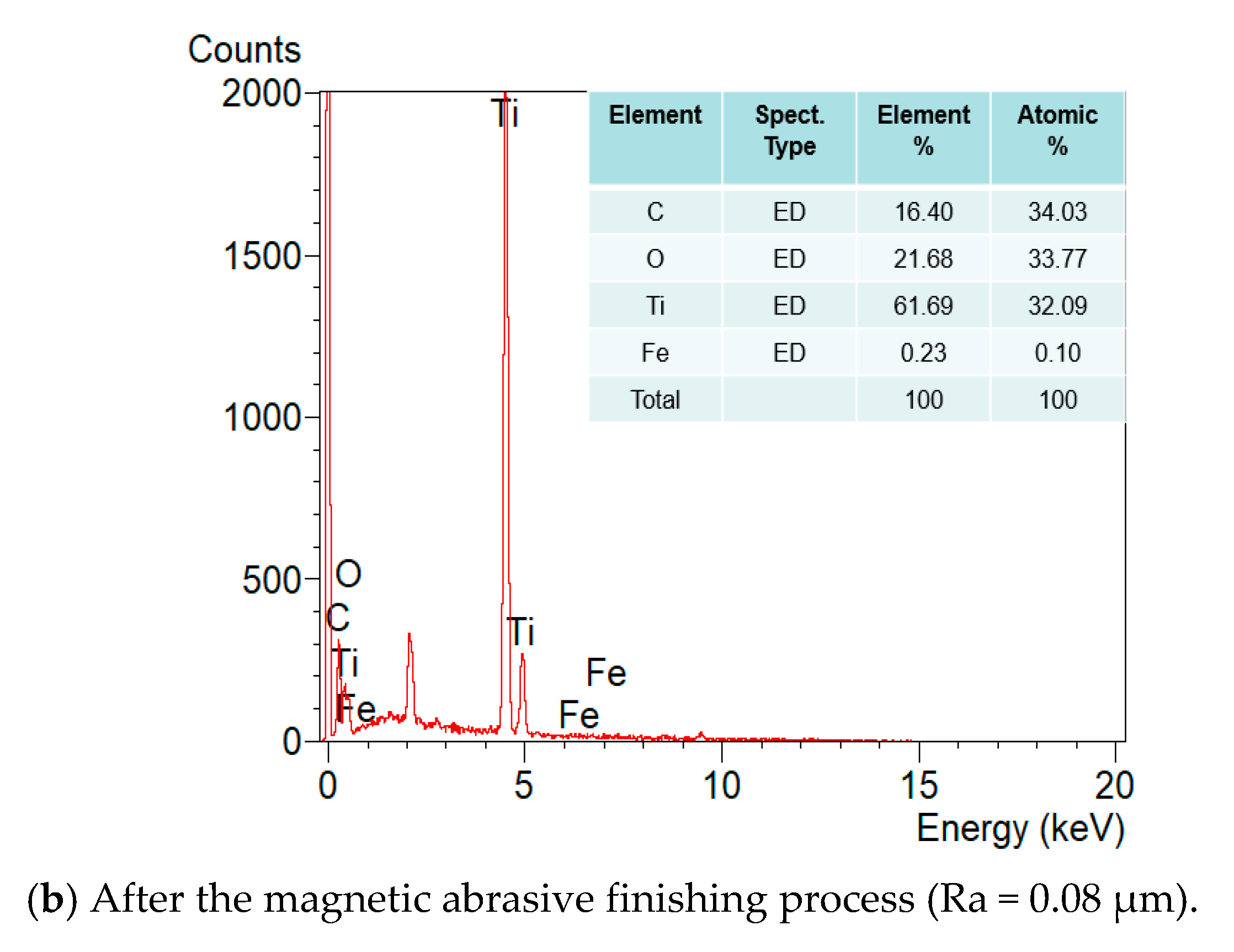
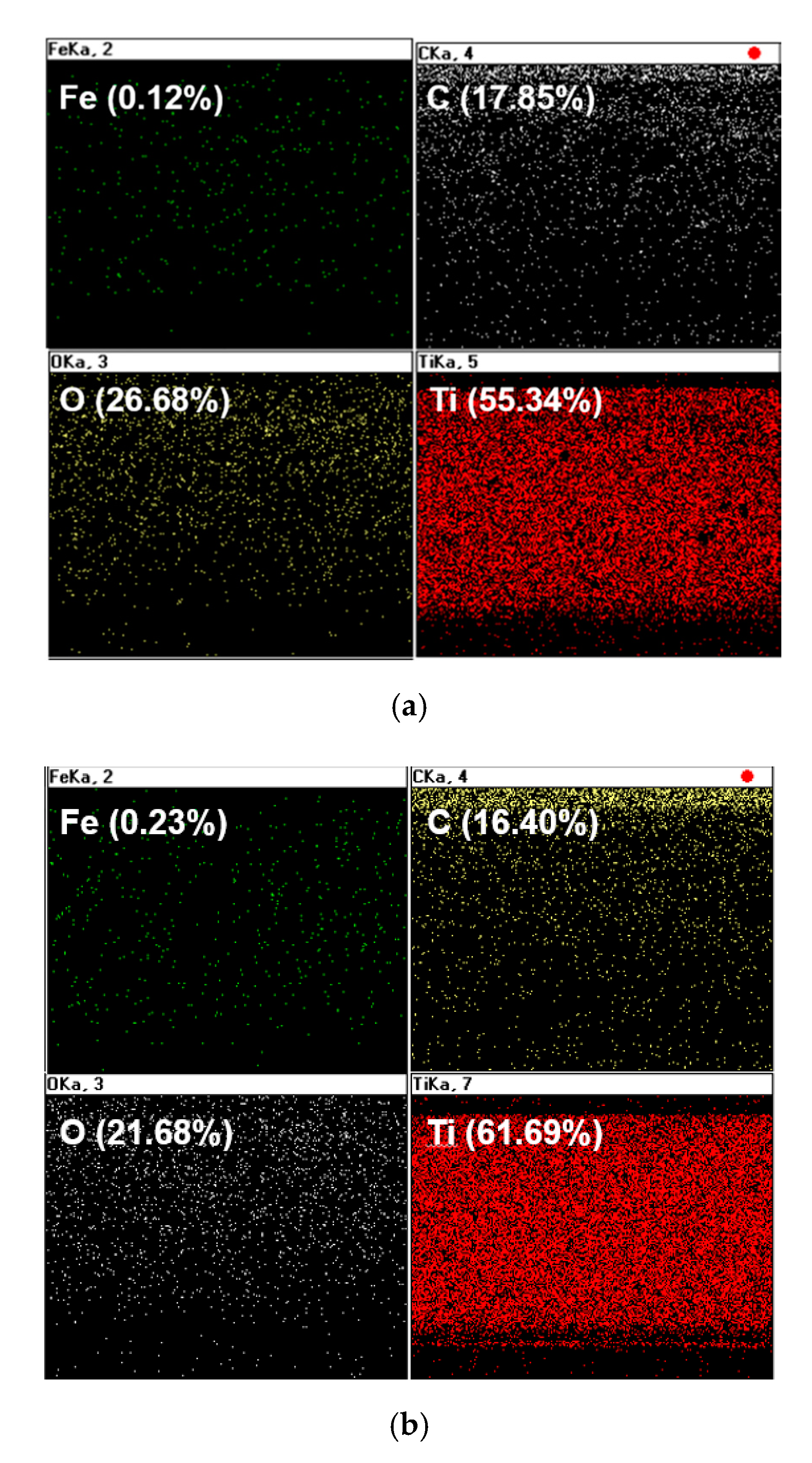
Figure 10 shows EDS chemical component analysis graphs for beta-titanium wire before and after processing. Figure 10a shows the chemical components of the material detected on the surface of the beta-titanium wire alloy workpiece prior to the finishing process: 55.34% Ti, 26.68% O, 17.85% C, and 0.12% Fe. After the finishing process, Figure 10b shows a composition of 16.40% C, 21.68% O, 61.69% Ti, and 0.23% Fe. Ti and Fe increased after processing, and O and C were lower. However, no other components were found on the surface of the workpiece after the finishing process. This confirmed that the component magnetic abrasive tools did not affect the surface of the workpiece after the finishing process. Figure 11 shows the EDS chemical composition maps on the surface of the workpiece before and after the finishing process with optimal conditions. Table 4 shows the chemical composition of β-titanium wire before and after finishing.

3.4. Influence of Multiple Transport Movement

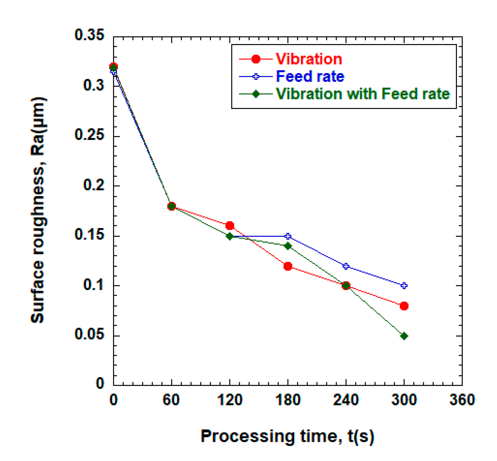
Experiments were conducted in three different ways to determine the processing characteristics associated with multiple transport movement. The optimal conditions (2000 rpm; 1 μm; sharp edge, finishing gap: 3 mm) obtained from the previous experiments were used, and the surface characteristics of the wire before and after processing were analyzed using the atomic force microscopy (AFM) 3D-micro images. Figure 12 shows the changes in surface roughness as a function of processing time for different transfer motion methods. In this experiment, the vibration factor was modified in the multi-transportation system, but when finishing time increased to 300 s, the processing performance was improved, and the surface roughness of the workpiece improved to 0.08 μm. The second experiment was conducted using only the feed rate provided by the rotational spools. In this case, the value of Ra was improved to 0.1 μm, which was not as good as the vibration single movement. Finally, vibration and feed rate were both employed at the same time. These results showed the best performance in terms of the surface roughness, showing improvement from 0.32 μm Ra to 0.05 μm Ra. Figure 13 shows the AFM 3D images of the workpiece before and after the various finishing processes: (a) before finishing, (b) vibration with feed rate (8 Hz, 80 mm/min), (c) vibration (8 Hz), (d) feed rate (80 mm/min). As shown in Figure 13, the initial surface of the workpiece was improved in all the conditions. However, better surface conditions were obtained using vibration with feed rate (see Figure 13b).

4. Conclusions

Experiments were conducted to find the optimal processing conditions for beta-titanium. The conclusions are as follows:
  • When the grain size of magnetic abrasive material changed at a fixed speed of 1500 rpm, the surface roughness (Ra) was improved to 0.05 μm.
  • When the rotational speed was changed and the particle size was fixed at 1 μm, the best results were obtained at a speed of 2000 rpm.
  • Better finishing was observed at a finishing gap of 3 mm than 5 mm.
  • In all conditions, AFM surface roughness measurements showed that the processed material had a smoother surface than before the machining.
  • When finishing using a multi-transfer motion method under optimal conditions, the processing effects were best to worst in the order: vibration with feed rate, vibration only and feed rate only.
  • Finally, we found that the magnetic abrasive finishing process using a Nd-Fe-B rare earth permanent magnet showed the best effect when the rotational speed was 2000 rpm and 1 μm abrasive material was used with a 3 mm finishing gap and a multi-transfer motion method.

Author Contributions

Design experiment and conceptualization, S.S.N.; methodology and performed experiments, S.S.N. and J.S.K.; investigation and editing, S.D.M.; writing paper, S.S.N. All authors have read and agreed to the published version of the manuscript.

Funding

This research was funded by NATIONAL RESEARCH FOUNDATION (NRF) of Korea in 2016, 2019 (Research Project No. 2016R1D1A1B03932103, 2019R1F1A1061819).

Acknowledgments

The authors appreciate the support from National Research Foundation of Korea (Project No. 2016R1D1A1B03932103, 2019R1F1A1061819) and appreciate the support from Ultra-Precision Finishing Lab for supporting the valuable discussion and guidance on the surface finishing technique.

Conflicts of Interest

The authors have no conflict of interest to declare.

References

  1. Choi, S.-Y.; Hwang, C.-U.; Kwon, D.-G. Analysis of Machined Surface Morphology According to Changes of Surface Condition in Micro Particle Blasting. Korean Soc. Manuf. Process. Eng. 2018, 17, 70–75. [Google Scholar] [CrossRef]
  2. Zou, Y.; Xie, H.; Dong, C.; Wu, J. Study on complex micro surface finishing of alumina ceramic by the magnetic abrasive finishing process using alternating magnetic field. Int. J. Adv. Manuf. Technol. 2018, 97, 2193–2202. [Google Scholar] [CrossRef]
  3. Kaur, M.; Singh, K. Review on titanium and titanium based alloys as biomaterials for orthopaedic applications. Mater. Sci. Eng. C 2019, 102, 844–862. [Google Scholar] [CrossRef] [PubMed]
  4. Heng, L.; Yin, C.; Han, S.H.; Song, J.H.; Mun, S.D. Development of a New Ultra-High-Precision Magnetic Abrasive Finishing for Wire Material Using a Rotating Magnetic Field. Materials 2019, 12, 312. [Google Scholar] [CrossRef] [PubMed] [Green Version]
  5. Wu, J.; Zou, Y.; Sugiyama, H. Study on finishing characteristics of magnetic abrasive finishing process using low-frequency alternating magnetic field. Int. J. Adv. Manuf. Technol. 2015, 85, 585–594. [Google Scholar] [CrossRef]
  6. Singh, G.; Singh, A.K.; Garg, P. Development of magnetorheological finishing process for external cylindrical surfaces. Mater. Manuf. Process. 2017, 32, 581–588. [Google Scholar] [CrossRef]
  7. Heng, L.; Yang, G.E.; Wang, R.; Kim, M.S.; Mun, S.D. Effect of carbon nano tube (CNT) particles in magnetic abrasive finishing of Mg alloy bars. J. Mech. Sci. Technol. 2015, 29, 5325–5333. [Google Scholar] [CrossRef]
  8. Chang, G.-W.; Yan, B.-H.; Hsu, R.-T. Study on cylindrical magnetic abrasive finishing using unbonded magnetic abrasives. Int. J. Mach. Tools Manuf. 2002, 42, 575–583. [Google Scholar] [CrossRef]
  9. Parameswari, G.; Jain, V.K.; Ramkumar, J.; Nagdeve, L. Experimental investigations into nanofinishing of Ti6Al4V flat disc using magnetorheological finishing process. Int. J. Adv. Manuf. Technol. 2017, 100, 1055–1065. [Google Scholar] [CrossRef]
  10. Choi, S.-Y.; Kwon, D.K. A Study of the Effectives for Surface Roughness by Cutting Angle and Cutting Fluid. Korean Soc. Manuf. Process. Eng. 2018, 17, 57–62. [Google Scholar] [CrossRef]
  11. Bae, J.-K.; Ahn, D.-H.; Kwon, B.-C.; Ko, S.L. Development of Efficient Brush Deburring Process for Valve Body of Auto Transmission. Korean Soc. Manuf. Process. Eng. 2018, 17, 144–152. [Google Scholar] [CrossRef]
  12. Yin, C.; Heng, L.; Kim, J.S.; Kim, M.S.; Mun, S.D. Development of a New Ecological Magnetic Abrasive Tool for Finishing Bio-Wire Material. Materials 2019, 12, 714. [Google Scholar] [CrossRef] [PubMed] [Green Version]
  13. Alam, Z.; Khan, D.A.; Jha, S. A study on the effect of polishing fluid volume in ball end magnetorheological finishing process. Mater. Manuf. Process. 2017, 33, 1197–1204. [Google Scholar] [CrossRef]
  14. Liu, S.; Shan, X.; Guo, K.; Yang, Y.; Xie, T. Experimental study on titanium wire drawing with ultrasonic vibration. Ultrasonics 2018, 83, 60–67. [Google Scholar] [CrossRef] [PubMed]
  15. Song, J.; Shinmura, T.; Mun, S.D.; Sun, M. Micro-Machining Characteristics in High-Speed Magnetic Abrasive Finishing for Fine Ceramic Bar. Metals 2020, 10, 464. [Google Scholar] [CrossRef] [Green Version]
  16. Nagdeve, L.; Sidpara, A.M.; Jain, V.K.; Ramkumar, J. On the effect of relative size of magnetic particles and abrasive particles in MR fluid-based finishing process. Mach. Sci. Technol. 2017, 22, 493–506. [Google Scholar] [CrossRef]
  17. Zeng, Z.; Cong, B.; Oliveira, J.; Ke, W.; Schell, N.; Peng, B.; Qi, Z.; Ge, F.; Zhang, W.; Ao, S. Wire and arc additive manufacturing of a Ni-rich NiTi shape memory alloy: Microstructure and mechanical properties. Addit. Manuf. 2020, 32, 101051. [Google Scholar] [CrossRef]
Figure 1. Experimental setup of magnetic abrasive finishing process for beta-titanium wire.
Applsci 10 06729 g001
Figure 2. Magnetic abrasive finishing equipment for beta-titanium wire using Nd-Fe-B permanent magnet.
Applsci 10 06729 g002
Figure 3. Schematic view of rotating magnetic field generator for beta-titanium wire: (a) 3D view of rotational magnetic field device and (b) 2D dimensional view of the rotational magnetic field device.
Applsci 10 06729 g003
Figure 4. Surface roughness (Ra) vs. processing time for different diamond paste sizes (vibration: 8 Hz; rotation: 1500 rpm; sharp edge; gap: 3 mm).
Applsci 10 06729 g004
Figure 5. Surface roughness (Ra) vs. processing time as a function of rotational speed (vibration: 8 Hz; abrasive: 1 μm; sharp edge; gap: 3 mm).
Applsci 10 06729 g005
Figure 6. Front view of sharp-edged magnetic field analyzed by FEMM.
Applsci 10 06729 g006
Figure 7. Magnetic flux density (T) vs. distance for different finishing gaps.
Applsci 10 06729 g007
Figure 8. Surface roughness (Ra) vs. processing time for different finishing gaps (vibration: 8 Hz; abrasive: 1 μm; rotation: 2000 rpm; sharp edge magnetic pole).
Applsci 10 06729 g008
Figure 9. Micro-images of surface roughness before and after finishing: (a) before finishing (Ra = 0.32) and (b) after finishing (Ra = 0.05).
Applsci 10 06729 g009
Figure 10. EDS graphs of the workpiece before and after the magnetic abrasive finishing process (under optimal conditions: 1 μm, 3 mm, 2000 rpm, 300 s).
Applsci 10 06729 g010aApplsci 10 06729 g010b
Figure 11. EDS chemical composition mapping of before and after processing the workpiece: (a) before finishing Ra = 0.32 and (b) after finishing Ra = 0.08.
Applsci 10 06729 g011
Figure 12. Surface roughness (Ra) vs. finishing time for multi-feed movement (vibration: 8 Hz; abrasive: 1 μm; rotation: 2000 rpm; finishing time: 300 s; sharp edge).
Applsci 10 06729 g012
Figure 13. Atomic force microscopy (AFM) 3D image of the workpiece before and after finishing process according to multi-transportation system employed.
Applsci 10 06729 g013
Table 1. Chemical composition of β-titanium wire.
ComponentNCH
Chemical composition
(Max%)
0.030.080.015
ComponentOFeTi
Chemical composition
(Max%)
0.180.2Remainder
Table 2. Mechanical properties of β-titanium wire.
Mechanical
Properties
Matrix
Tensile strength (MPa)345
Yield strength (MPa)220
Elongation (%)35
Hardness (HV)115
Elastic modulus (GPa)115
Density (g/m3)4.51
Table 3. Experimental conditions.
Workpiece materialβ-titanium wire (L = 50 mm, D = 0.5 mm)
Electrolytic iron powder1.2 g (#200)
Diamond paste (PCD)(0.5, 1, and 3 μm) 0.6 g
CNT particle0.02 g
Lubricant0.3 mL (light oil)
MagnetNd-Fe-B permanent magnet (Size: 20 mm × 10 mm × 10 mm)
Magnetic pole vibrationAmplitude: 2 mm
Finishing gap3 mm, 5 mm
Rotational speed700, 1500, 2000 rpm
Finishing time0, 60, 120, 180, 240, 300 s
Vibration frequency8 Hz
Feed rate80 mm/min
Table 4. Chemical composition of β-titanium wire before and after finishing.
ElementChemical Composition (%)
before Processing
Chemical Composition (%)
after Processing
C17.8516.40
O26.6821.68
Ti55.3461.69
Fe0.120.23
Total100100