Abstract
In this study, the effect of the presence of horizontal fins on the safe operating time (SOT) of the PCM filled heat sink was examined. The effects of the number of horizontal fins, as well as fins length on SOT at different aspect ratios, was investigated. Horizontal fins, owing to their high thermal conductivity, cause uniformity in temperature distribution and improve the heat sink thermal conductivity (positive effect). Incorporating horizontal fins reduces the PCM volume fraction which consequently diminishes the ability of the heat sink to absorb the thermal energy (negative effect). The competition between the former effect and the latter determines the efficacy of adding horizontal fins in the PCM filled heat sinks. As the number of horizontal fins increases up to five, the positive effect is superior to the negative one which in turn enlarges the safe operation time. By the further increase in the number of fins, the negative effect prevailed over the positive effect and therefore the safe operation time diminished. As the heat sink aspect ratio increased, convection heat transfer efficacy becomes more apparent. In this case, it is recommended to use horizontal fins with shorter lengths so that the PCM movement is not disturbed.
1. Introduction
Phase change materials (PCMs) have a high ability to store thermal energy [1,2]. Usually, they have high phase change enthalpy, hence during the phase change, absorb a great amount of energy at the low-temperature range (phase change temperature) [3]. Therefore, it seems that these materials can also be utilized to cool the electronic devices [4] due to their high energy storage capability [5]. Ren et al. [6] performed a numerical study on the potential of microencapsulated phase change material (MEPCM) on holding the temperature increase in electronic devices. They used expanded graphite (EG) nanoparticles with fin to enhance the thermal conductivity of MEPCM, but preliminary results showed that although fin improves the thermal conductivity of the heat sink, it also reduces the latent heat storage capability. They investigated two distinct heat sinks, the first heat sink used fin and the second one utilized EG nanoparticles to improve MEPCM thermal conductivity. In the early stages, the performance of the former heat sink was much better than the latter one, but over time, the performance of the latter one became better. The authors also showed that if multiple PCM with different melting temperatures were used, thermal performance would be improved. The authors recommend that MEPCM with a higher melting temperature should be used near the heat source. By moving away from the heat source, the MEPCM melting temperature must also be reduced. Emam et al. [7] applied three PCMs of RT25, RT35, and RT44 for cooling of the electronic device under heat fluxes of 2000, 2950 and 3750 W m−2. They observed that the base temperature of electronic devices which are equipped with PCMs, was lower by 69.8, 80.44, and 74.44 °C than the simple device. The authors also investigated the effects of ambient temperature in the solidification duration and it was found that as the ambient temperature increased from 20 to 25 °C, the solidification time of RT44HC raised by 94 min. This figure for the ambient temperature of 30 °C was 178 min. Farzanehnia et al. [8] used paraffin PCM for the cooling of an electronic chipset. They also incorporated multi-walled carbon nanotubes (MWCNTs) nanoparticles to enhance the PCM thermal conductivity. Three heat sinks were prepared and examined to evaluate the effects of using PCM on the electronic device cooling. The first heat sink was simple, while the second and third ones were filled with PCM. In the third heat sink, in addition to PCM, nanoparticles of MWCNT were also added. It was found that adding MWCNTs into the PCM led to a cooling time reduction up to 6%. In the active mode, incorporation of PCM and NPCM reduced the rate of increases in temperature in the early stages of the heating process, while intensified the chipset temperature in the steady state conditions. Huang et al. [9] conducted many experimental tests to examine the thermal behavior of a novel PCM-based heat sink. They found that PCM layer thickness, PCM thermal conductivity, heat storage density and finally power load has an impact on the thermal behavior. At high input power, the PCM role in the thermal performance of the heat sink was more obvious than the conditions in which the input power is low. Heat thermal storage improvement led to more operation time of the device prior to reaching the critical temperature. The authors also observed that the PCM thermal conductivity increases the safe operation time slightly. Also, they revealed that the PCM thickness efficacy on the safe operation time was more than the PCM thermal conductivity. Zhao et al. [10] compared the ability of a new low-melting-point alloy (LMPA) with paraffin of RT60 (both of them has approximately the same melting point). LMPA thermal conductivity was 50 times than the RT60 one. Also, LMPA volumetric latent heat storage was 2.1 times that of RT60. Results showed that using LMPA rather than the paraffin enlarged the safe operation time up to 50%. At the same time of operation, the maximum temperature in the heat sink equipped with LMPA was 15 °C lower than the RT60 one. Hafiz and Arshad [11] evaluated a PCM-based heat sink equipped with pin fins (fin diameters ranged from 2 to 4 mm). A base heat sink (without fin) was also prepared for comparison. The volume fraction of fins was 9% but the PCM volume fraction was considered variable. In other words, the PCM height varied within the heat sink. According to the results, the 3 mm diameter pin fin have more ability to extend the safe operating time than the other cases. Also, they found that the heat sink should be filled with PCM as much as possible.
As mentioned, high-temperature gradients are caused owing to the PCM low conductivity, which eventually reduces the rate of phase change, and it is likely that large amounts of PCM will not melt. Using high conductivity metal fins is and useful approaches to improve PCMs thermal conductivity (positive effect). But adding fins rises the system weight as well as the reduction in thermal energy storage potential (negative effect) due to the decrease in volume of materials with high phase change enthalpy (reduced PCM). Therefore, finding the optimal amount of fin is indispensable. The other negative effect of incorporation horizontal fins is the disruption to the convection heat transfer. In this study, the thermal behavior of a PCM-based heat sink in the presence of horizontal fins was numerically investigated. These types of heat sink can be effective in electronic cooling applications. Independent variables included aspect ratio, number of horizontal fins and length ratio, while the objective function was defined to maximize the safe operation time (SOT). Finally, the competition between the positive and negative effects of adding fins will be discussed.
2. Problem Description
As shown in Figure 1, PCM fills the gap between the horizontal fins. Paraffin wax (Table 1) is considered as PCM. The heat flux enters through the lower surface. Due to the expanding the melted PCM, a space (air) above the heat sink is provided as shown in Figure 1.
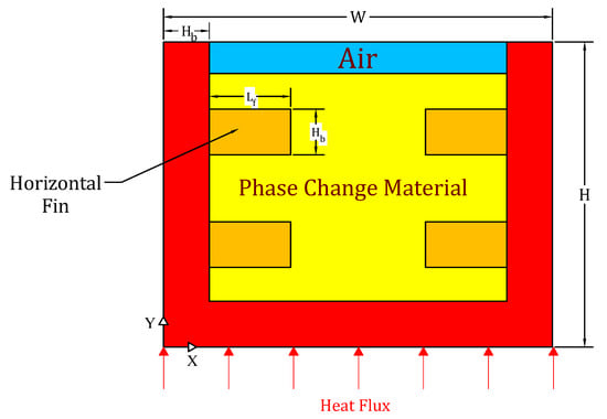
Figure 1.
PCM filled heat sink equipped with two horizontal fins .

Table 1.
PCM properties [12].
The density of PCM in the solid state is constant while in the liquid state, it is changed by . Note that Tl is the liquidus temperature (Table 1). Fins are made of aluminum alloy 6061 with constant thermophysical properties of cp = 875 J kg−1 K−1 and k = 177 W m−1 K−1.
The heat sink area is considered to be constant (problem constraint). Input parameters are defined as the aspect ratio , length ratio and fins number Note that the fin thickness was considered to be constant . The objective function was defined to maximize safe operation time (SOT). The applied heat flux changes so that the input energy per the total volume of heat sink remains constant. In other words, the value of is constant for all PCM filled heat sinks. The initial temperature is considered to be the same as the ambient temperature (27 °C). Following Table 1, at 27 °C, PCM is in the solid state. All walls (except the lower wall) are considered adiabatic. Under the worst conditions, all energy enter to the heat sink must be absorbed by the PCM. Note that the boundary condition at the lower surface is . In studies involving PCM, the volume fraction of PCM indicates what fraction of the heatsink is occupied by PCM:
3. Mathematical Formulation
In this study, two-phase heat transfer formulation is investigated [13,14,15]. There are two interfaces in this study [16]. The location of the interface between air and PCM (Figure 1) is tracked by using of the volume of fluid (VOF) technique. In the VOF technique, the momentum equations along the horizontal and vertical directions with modified properties are used [17]:
Due to the presence of two phases of PCM and air, modified thermophysical properties such as ρ, k and μ can be obtained by the following equations:
In the above equations, denote the air volume fraction and obtained by the following Equation:
Note that the PCM volume fraction is determined with .
The well-known enthalpy-porosity technique is used for the PCM phase change process [18]. In this technique, the interface between solid and liquid is not explicitly tracked. In the enthalpy-porosity approximation, the cell domain is considered as a porous medium and the amount of porosity indicates the liquid fraction . For , the cell temperature is higher than the liquidus temperature , but the liquid fraction equal to zero indicates that the cell temperature is lower than the solidus temperature . For the cell temperature between Ts and Tl, the liquid fraction is between zero and one, and in this case, there is an interface between the liquid and solid phases [19]. The energy equation for problems involving phase change process is written as follow:
where h denote the sensible enthalpy and is the latent enthalpy which is related to the amount of liquid fraction . Note that is the phase change enthalpy. Second-order upwind and geo reconstruct discretization methods were applied on momentum/energy and liquid fraction equations, respectively. Considering the low velocity in the phase change process, the laminar flow is considered. The convergence criteria for energy, velocity and continuity equations was selected to be , and , respectively.
4. Grid Study and Validation
For computational grid independency, three computational grids with interval sizes of 0.2, 0.1 and 0.05 were selected. According to the results, as the interval size decreased from 0.1 to 0.05, the SOT did not change significantly. Therefore, a structured computational grid (interval size of 0.1 mm) was chosen. Figure 2 shows the effect of time step size variation on the output response . As can be seen, reducing the time step up to 0.01 s, SOT decreases. Further reduction of the time step does not have a significant effect on SOT.
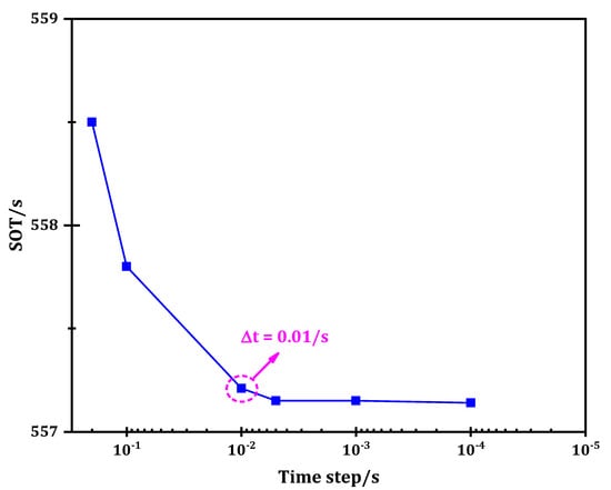
Figure 2.
Independency of the time step size .
The numerical method used in this study was validated by experiments carried out by Hosseinizadeh et al. [20]. The authors studied a PCM-based heat sink equipped with vertical fins to enhance the heat sink thermal conductivity. The electrical power applied to the bottom wall was 45 W, while the other walls were well insulated. The ambient temperature was 27 °C, hence the heat sink initial temperature was 27 °C. Applying heat flux on the bottom wall, its temperature begins to rise. The temperature variations of the bottom wall are shown in Figure 3. As can be seen, the base temperature variations can be divided into three zones. In the first and third zones, the rate of the variations (slope) is greater than in the middle zone. In the middle zone, the PCM undergoes phase change. The thermal energy in this zone is stored as the latent heat, but in the other two zones, the heat stored is sensible. The same trend can be seen for the simulated results. As shown, the numerical method can well predict the temperature variations of the PCM-based heat sink at three zones.
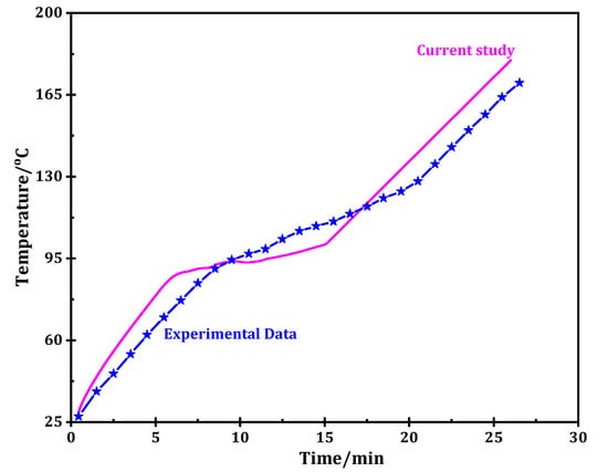
Figure 3.
Comparison between the current study and the experimental data [20].
5. Results
In general, by loading fins to the PCM, heat transfer within the PCM can be enhanced to maximize the objective function. The objective function is different for various applications. In electronic cooling applications, the objective function is defined as enlarging SOT. For this purpose, given the problem constraints (constant volume of the heat sink), the optimal number of horizontal fins within PCM will be examined. The presence of horizontal fins is expected to improve heat distribution within the PCM. For this purpose, the variations of SOT in the PCM filled heat sink equipped with horizontal fins was compared with the corresponding value in the PCM filled heat sink (without horizontal fins). The variations of SOT are shown in Figure 4.
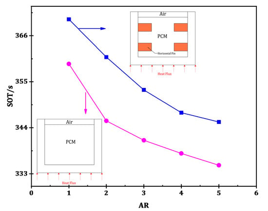
Figure 4.
The variations in SOT owing to the incorporation of horizontal fins into the PCM filled heat sink.
As can be seen in Figure 4, by adding horizontal fins, the contact surface between PCM and fins intensified which consequently increased the objective function in each aspect ratio . The results presented in Figure 4 are for a heat sink equipped with three horizontal fins at length ratio of LR = 0.3. As can be seen in Figure 4, as the horizontal fins were incorporated to the PCM, the contact surface area intensified which consequently improved the conductive heat transfer, hence SOT is improved. Therefore, it is desirable to add horizontal fins. To evaluate the effects of the number as well as the length of horizontal fins on heat sink performance, a heat sink at a constant height of is selected. Some horizontal fins at length ratios of LR = 0.3, 0.5, 0.7 and 0.9 were loaded at 5000 applied from the bottom surface. For the heat sink with three horizontal fins , the effects of length ratio on are shown in Figure 5.

Figure 5.
The effect of increase in length ratio (LR) on SOT (H = 10 mm, three horizontal fins (n = 3), AR = 1).
As shown in Figure 5, with the rise in the length ratio (equivalent with the fins length growth), SOT increases. In Figure 6, the streamlines are illustrated for both LR = 0.3 and LR = 0.9. As shown in Figure 6, as the horizontal fin length rises, the contact area, as well as the convection intensity increased, which consequently SOT improves.

Figure 6.
Comparison of the convection strength between LR = 0.3 and LR = 0.9 (n = 3, H = 10 mm, AR = 1).
Now, the number of horizontal fins efficacy is examined. By increasing the horizontal fins from 3 to 13, the SOT was recorded and shown in Figure 7. However, for a convenient understanding of the effect of the number of horizontal fins (n), the results were summarized for n = 3, 5, 11 and 13 as illustrated in Figure 7.
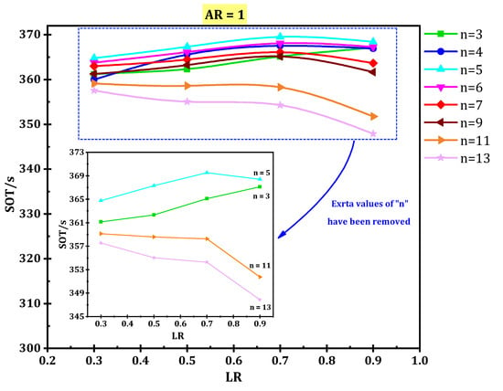
Figure 7.
Effects of length ratio (LR) on SOT at different horizontal fins number (H = 10 mm).
When the number of horizontal fins is five (n = 5), increasing the fin length from the LR = 0.3 to LR = 0.7 improves the SOT, but more increase in LR, diminishes SOT. The incorporation of horizontal fins has a positive effect (thermal conductivity enhancement) as well as a negative effect (latent heat reduction). As shown in Figure 7, the optimal number of horizontal fins is five. As the number of fins rises up to five, the incremental effect of thermal conductivity improvement (positive effect) was superior to the decremental effect of the latent heat reduction (negative effect), hence the objective function (SOT) improved. However, with a further increase in the number of fins upon five, the negative effect prevailed over the positive effect and therefore the safe operation time diminished.
In a study conducted by Kalbasi and Salimpour [12], using constructal theory, it was shown that under the best conditions, the number of horizontal fins is equal to four. In [12], the heat flux input to the heat sink was considered to be constant. Of course, with increasing the aspect ratio, the input energy also increases. In this study, the input energy for all heat sinks was considered constant. However, in this study, as can be seen in Figure 7, the number of optimal horizontal fins is equal to five, which is very close to the corresponding value in [12].
In Figure 8 the streamlines for the three LR values (0.3, 0.7 and 0.9) are depicted. As can be seen, at length ratio of LR = 0.7, the convection is formed in two places (between the horizontal fins and the distance between the horizontal fin tip and the line of symmetry). But at LR = 0.5 and LR = 0.9 the convection is formed only in one place. The presence of streamlines in each zone indicates that there is a liquid phase motion which implies the possibility of the natural convection heat transfer.
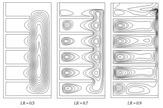
Figure 8.
Convection strength at LR = 0.5, 0.7 and 0.9 (n = 5, H = 10 mm).
It seems that the liquid phase movement at LR = 0.7 is much better than the other two cases (LR = 0.5 and 0.9). Because the streamlines are well distributed throughout the heat sink, hence that the possibility of the liquid phase movement is higher at LR = 0.7. At LR = 0.5, the liquid phase does not move well in the space between the horizontal fins. In the third case (LR = 0.9), due to the long length of the horizontal fins, it is difficult to establish a connection between the space of each fin. In other words, the liquid phase movement is blocked due to the long length of the horizontal fins. Therefore, it seems that the convection strength for LR = 0.7 is superior to LR = 0.7 and LR = 0.7, which consequently leads to higher objective function.
As can be seen in Figure 9, for heat sink with 13 horizontal fins, adding larger fins disrupt the convection. As shown in Figure 9, the liquid PCM movement is disturbed owing to an increase in fins length, hence the convection intensity reduces. For this reason, reduces with increasing fins length for heat sink with 13 horizontal fins as shown in Figure 7.
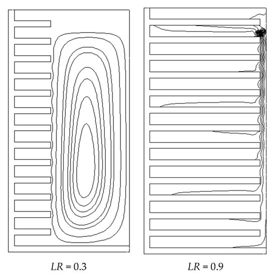
Figure 9.
Comparison of strength convection between LR = 0.3 and LR = 0.9 (n = 13, H = 10 mm).
Considering the constant heat sink height, as the heat sink width grows, the aspect ratio increases. The effects of increasing AR on are shown in Figure 10. According to Figure 10, the increase in AR does not affect the number of optimum fins. That is, for H = 10 mm from AR = 1 to AR = 5, the optimal fin number is 5 (i.e., nopt = 5). As mentioned, adding fin has a positive effect (thermal conductivity enhancement) as well as a negative effect (latent heat reduction). As the number of fins rises up to five, it seems that the incremental effect of thermal conductivity improvement (positive effect) is superior to the decremental effect of the latent heat reduction (negative effect), hence the objective function improved. However, by increasing the number of fins from 5 to 13, the negative effect prevails over the positive effect and therefore the objective function will diminish. As the aspect ratio grows , the horizontal distance between the vertical walls increases, hence the conduction heat transfer diminished. In this case, convection heat transfer has a larger role in . In other words, as AR grows, the role of convection heat transfer in the objective function becomes more important and therefore the optimal length ratio should be reduced. As shown in Figure 10, the optimal length ratio LR decreases with increasing AR.
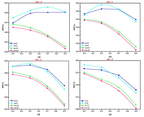
Figure 10.
Optimum fins number at different AR.
Following Figure 10 (AR = 5), the objective function diminishes as the length ratio (LR) grows. Because at high aspect ratio (AR), convection heat transfer plays a key role, and the shorter the fin length, the greater convection intensity there will be (Figure 11).
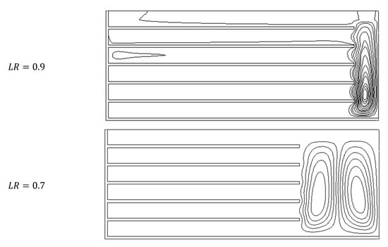
Figure 11.
Streamlines at LR = 0.7 and LR = 0.9 (H = 10 mm, n = 5, AR = 5).
It was mentioned that the optimal fin number for H = 10 mm is five (i.e., nopt = 5). Now, the effects of increase in the heat sink height on the number of optimal fins are investigated. The sensitivity of the objective function to n and LR at different heat sink height of 12.5, 15, 17.5 and 20 mm was illustrated in Figure 12. According to Figure 12, the optimal fins number at heights of 12.5, 15, 17.5 and 20 mm is also five (i.e., nopt = 5). It seems that by increasing the number of fins up to five, the positive effect of fin installation was superior to its negative effect, but by increasing the number of fins from 5 to 13, the negative effect (decreasing the phase change enthalpy overcomes the positive effect (increase in thermal conductivity), hence SOT decreases. Focusing on Figure 12 revealed that the optimum length ratio (LRopt) is in the range of 0.3 to 0.7. Note that LRopt is the LR which maximize the SOT.
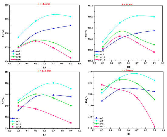
Figure 12.
The variation in SOT with respect to LR at different heat sink height.
PCM Volume Fraction Variations
As the horizontal fins installed, the PCM volume decreases. For the base heat sink (without horizontal fins), the PCM volume fraction variations in terms of AR are shown in Figure 13. As the aspect ratio increases from 1 to 5, the PCM volume fraction (for base heat sink) rises from 0.926 to 0.965. To evaluate the variation in PCM volume fraction for heat sink equipped with the horizontal fins, the optimal number of fins along with appropriate length ratio (LR) must be determined from Figure 10 and then the optimal PCM volume fraction is calculated considering Equation (1). As shown in Figure 13, for heat sink with optimal fins number increases as the heat sink becomes wider.
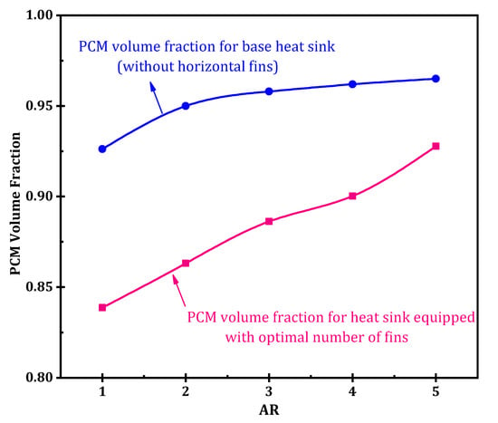
Figure 13.
Variations in PCM volume fraction for base heat sink and heat sink equipped with optimal number of horizontal fins.
Note that with increasing , the fin volume fraction decreases. As mentioned in Figure 11, with the increase in AR, the intensity of the convection heat transfer is amplified and therefore the presence of horizontal fins may disturb the liquid phase movement. Therefore with increasing AR, shorter fins perform better and therefore it is expected that with increasing aspect ratio, the fin volume fraction for the heat sink equipped with the optimal number of fins diminishes. Figure 13 shows that as AR rises, the optimal PCM volume fraction increases, which corresponds to a decrease in . This means that as the heat well widens, less fin volume fraction is required. Figure 13 shows that the PCM volume fraction of the studied base heat sinks has changed in the range of 0.92 to 0.97. However, installing horizontal fins reduces so that the optimal varies in the range of 0.83 to 0.93.
6. Conclusions
In this study, the thermal behavior of a PCM-based heat sink in the presence of horizontal fins was numerically investigated. The sensitivity of the objective function (SOT) to the input variables of the aspect ratio (AR), number of horizontal fins (n) and length ratio (LR) was evaluated. The most important results are as follows:
- Based on the results, the optimal number of horizontal fins was five. As the number of fins rises up to five, the incremental effect of thermal conductivity improvement (positive effect) was superior to the decremental effect of the latent heat reduction (negative effect), hence the objective function improved. However, for the increase in number of fins from 5 to 13, the negative effect prevailed over the positive effect and therefore the safe operation time diminished.
- The optimum length ratio for the horizontal fins depends on the aspect ratio. As the aspect ratio increases, it is recommended to use horizontal fins with a lower length ratio. However, the optimal value of the length ratio varied in the range of 0.3 to 0.7.
Author Contributions
A.M.: Writing, Methodology; H.M.: Writing, Methodology, Introduction, Investigating; S.A.-N.: Methodology, Data curation; R.K.: Writing, Conceptualization, Software, Validation; A.K.: Writing, Formal analysis; G.C.: Writing—review & editing, Formal analysis. All authors have read and agreed to the published version of the manuscript.
Funding
This research received no external funding.
Conflicts of Interest
There is no conflict of interest.
References
- Klimeš, L.; Charvát, P.; Joybari, M.M.; Zálešák, M.; Haghighat, F.; Panchabikesan, K.; El Mankibi, M.; Yuan, Y. Computer modelling and experimental investigation of phase change hysteresis of PCMs: The state-of-the-art review. ApEn 2020, 263, 114572. [Google Scholar] [CrossRef]
- Jeon, J.; Lee, J.-H.; Seo, J.; Jeong, S.-G.; Kim, S. Erratum to: Application of PCM thermal energy storage system to reduce building energy consumption. J. Therm. Anal. Calorim. 2013, 111, 279–288. [Google Scholar] [CrossRef]
- Beemkumar, N.; Yuvarajan, D.; Arulprakasajothi, M.; Elangovan, K.; Arunkumar, T. Control of room temperature fluctuations in the building by incorporating PCM in the roof. J. Therm. Anal. Calorim. 2020. [Google Scholar] [CrossRef]
- Rashidi, S.; Shamsabadi, H.; Esfahani, J.A.; Harmand, S. A review on potentials of coupling PCM storage modules to heat pipes and heat pumps. J. Therm. Anal. Calorim. 2020, 140, 1655–1713. [Google Scholar] [CrossRef]
- Sahoo, S.K.; Das, M.K.; Rath, P. Application of TCE-PCM based heat sinks for cooling of electronic components: A review. Renew. Sustain. Energy Rev. 2016, 59, 550–582. [Google Scholar] [CrossRef]
- Ren, Q.; Guo, P.; Zhu, J. Thermal management of electronic devices using pin-fin based cascade microencapsulated PCM/expanded graphite composite. Int. J. Heat Mass Transf. 2020, 149, 119199. [Google Scholar] [CrossRef]
- Emam, M.; Ookawara, S.; Ahmed, M. Thermal management of electronic devices and concentrator photovoltaic systems using phase change material heat sinks: Experimental investigations. Renew. Energy 2019, 141, 322–339. [Google Scholar] [CrossRef]
- Farzanehnia, A.; Khatibi, M.; Sardarabadi, M.; Passandideh-Fard, M. Experimental investigation of multiwall carbon nanotube/paraffin based heat sink for electronic device thermal management. Energy Convers. Manag. 2019, 179, 314–325. [Google Scholar] [CrossRef]
- Huang, Z.; Xie, N.; Zheng, X.; Gao, X.; Fang, X.; Fang, Y.; Zhang, Z. Experimental and numerical study on thermal performance of Wood’s alloy/expanded graphite composite phase change material for temperature control of electronic devices. Int. J. Therm. Sci. 2019, 135, 375–385. [Google Scholar] [CrossRef]
- Zhao, L.; Xing, Y.; Wang, Z.; Liu, X. The passive thermal management system for electronic device using low-melting-point alloy as phase change material. Appl. Therm. Eng. 2017, 125, 317–327. [Google Scholar] [CrossRef]
- Ali, H.M.; Arshad, A. Experimental investigation of n-eicosane based circular pin-fin heat sinks for passive cooling of electronic devices. Int. J. Heat Mass Transf. 2017, 112, 649–661. [Google Scholar] [CrossRef]
- Kalbasi, R.; Salimpour, M.R. Constructal design of horizontal fins to improve the performance of phase change material rectangular enclosures. Appl. Therm. Eng. 2015, 91, 234–244. [Google Scholar] [CrossRef]
- Shadloo, M.S. Numerical simulation of compressible flows by lattice Boltzmann method. Numer. Heat Transf. Part A Appl. 2019, 75, 167–182. [Google Scholar] [CrossRef]
- Almasi, F.; Shadloo, M.S.; Hadjadj, A.; Ozbulut, M.; Tofighi, N.; Yildiz, M. Numerical simulations of multi-phase electro-hydrodynamics flows using a simple incompressible smoothed particle hydrodynamics method. Comput. Math. Appl. 2019. [Google Scholar] [CrossRef]
- Shadloo, M.S.; Rahmat, A.; Karimipour, A.; Wongwises, S. Estimation of Pressure Drop of Two-Phase Flow in Horizontal Long Pipes Using Artificial Neural Networks. J. Energy Resour. Technol. 2020, 142, 1–21. [Google Scholar] [CrossRef]
- Ding, B.; Qi, Z.-H.; Mao, C.-S.; Gong, L.; Liu, X.-L. Numerical investigation on cooling performance of PCM/cooling plate hybrid system for power battery with variable discharging conditions. J. Therm. Anal. Calorim. 2020. [Google Scholar] [CrossRef]
- Voller, V.R.; Cross, M.; Markatos, N. An enthalpy method for convection/diffusion phase change. Int. J. Numer. Methods Eng. 1987, 24, 271–284. [Google Scholar] [CrossRef]
- Bouzennada, T.; Mechighel, F.; Filali, A.; Kolsi, L. Study of the usability of sinusoidal function heat flux based on enthalpy-porosity technique for PCM-related applications. J. Therm. Anal. Calorim. 2020. [Google Scholar] [CrossRef]
- Swaminathan, C.; Voller, V.R. A general enthalpy method for modeling solidification processes. Metall. Trans. B 1992, 23, 651–664. [Google Scholar] [CrossRef]
- Hosseinizadeh, S.F.; Tan, F.L.; Moosania, S.M. Experimental and numerical studies on performance of PCM-based heat sink with different configurations of internal fins. Appl. Therm. Eng. 2011, 31, 3827–3838. [Google Scholar] [CrossRef]
© 2020 by the authors. Licensee MDPI, Basel, Switzerland. This article is an open access article distributed under the terms and conditions of the Creative Commons Attribution (CC BY) license (http://creativecommons.org/licenses/by/4.0/).