Article

Mineral Carbonation of CO2 in Mafic Plutonic Rocks, I—Screening Criteria and Application to a Case Study in Southwest Portugal

1
Departamento de Geociências, Escola de Ciências e Tecnologia, Universidade de Évora, Rua Romão Ramalho, 59, 7000-671 Évora, Portugal
2
Instituto de Ciências da Terra, Universidade de Évora, Rua Romão Ramalho, 59, 7000-671 Évora, Portugal
3
Laboratório Hercules, Universidade de Évora, Largo Marquês de Marialva, 8, 7000-809 Évora, Portugal
4
Instituto Geológico y Minero de España, C/Matemático Pedrayes 25, 33005 Oviedo, Spain
*
Author to whom correspondence should be addressed.
Appl. Sci. 2020, 10(14), 4879; https://doi.org/10.3390/app10144879
Submission received: 16 June 2020 / Revised: 8 July 2020 / Accepted: 9 July 2020 / Published: 16 July 2020

Abstract

:
This article describes the screening, ranking and characterization of ultramafic and mafic rocks in southern Portugal for mineral carbonation as an alternative to conventional CO2 storage in sedimentary rocks. A set of criteria including mineralogy, structure, surface area, distance to CO2 sources, expected volume, and socioeconomic conditions was applied to screen ultramafic and mafic rock massifs in the Alentejo region, southern Portugal. Ranking of the massifs indicated that the plutonic massifs of Sines and of Torrão‒Odivelas were the most promising. A characterization was made of the Sines massif, a subvolcanic massif composed mostly of gabbros and diorites, located immediately adjacent to the CO2 sources and outcropping along 300 km2 onshore and offshore. These studies confirmed that these rock samples exhibited the appropriate mineralogical and geochemical features, but also indicated that the secondary porosity provided by the fracture patterns was very small.

1. Introduction

According to the International Energy Agency [1], achieving the Paris Climate Agreement targets of global warming below 2 °C by 2100 while developing efforts to limit temperature rising to 1.5 °C [2] implies wide scale deployment of CO2 capture, utilization, and storage (CCUS). The scenarios developed by the IEA by the 2060 CCUS should contribute to 14% of the required reduction in CO2 emissions to achieve a scenario where temperatures are less than 2 °C, or 32% to achieve the 1.5 °C limit scenario.
Portugal has been on the forefront of policies to reduce CO2 emissions, having established a roadmap to reach carbon neutrality by 2050 [3]. This policy has been reinforced by the Green Deal announced in December 2019 by the European Commission, which sets the same carbon neutrality target by 2050 for the European Union [4].
The roadmap does not explicitly consider CCUS as one of the technologies that should contribute to carbon neutrality in Portugal, although earlier studies have demonstrated that CCUS will be required in some industry sectors (e.g., cement) as early as 2030 [5,6].
According to the European Union carbon market database (EU ETS), in 2018, the Portuguese CO2 emissions from the industrial and power sectors amounted to 26.2 Mt CO2 [7], with the most important emissions cluster located in southern Portugal, extending from Setúbal to the Sines industrial area, being responsible for 44% of all emissions in the country (Figure 1a). Although the main point source in the region, the Sines Coal Power Plant, is to be decommissioned in 2023, the remaining sources will account for more than 30% of all emissions from industrial sources (Figure 1b). Furthermore, the socioeconomic relevance of the industry to the region imposes the need to seek alternatives to decarbonization in the region.
The possibility of capturing CO2 at the Sines and Setúbal sources and storing it in offshore deep saline aquifers was addressed previously [8,9], but was decided against due to low storage capacity and high storage costs. The possibility of CO2 transport to other parts of the country with more favorable geological storage conditions was studied in Seixas et al. [6] and is being further pursued in the STRATEGY CCUS project [10], funded by the European Union’s Horizon 2020 to study the development of CCUS in Southern and Eastern Europe, including a promising region in Portugal.
Nonetheless, the multiple ultramafic and mafic rock massifs in Alentejo could provide an alternative for CO2 storage by mineral carbonation. The potential of ultramafic and mafic rocks for CO2 storage rests in their ability to stabilize CO2 via mineral carbonation (e.g., [11,12,13,14]). These rocks are enriched in Ca2+, Mg2+, and Fe2+ silicate minerals, which react with CO2 precipitate carbonate minerals [15], leading to the trapping of the CO2 in a solid phase at a much faster rate than can be expected in sedimentary silicate rocks. The feasibility of this process was demonstrated in the CarbFix (Iceland) project [16] and Wallula (USA) project [17], in a process designated as in situ mineral carbonation, in which CO2 is dissolved in water and injected into basalts. However, extensive studies have also addressed an ex situ process, in which the ultramafic and mafic rocks are mined and the mineral carbonation process takes place in plants under optimized pressure and temperature conditions [18,19,20]. A third possibility that has been put forward as a geo-engineering technique is the utilization of ultramafic rocks to sequester CO2 through enhanced weathering, in which the mined and crushed rock is spread in large areas under atmospheric conditions to react with CO2, promoting direct CO2 capture from the air [21,22].
Plutonic rocks, with a mineralogical and geochemical composition similar to basalts have, to the best of our knowledge, not been considered for in situ mineral carbonation, since the low porosity is seen as an impediment to industrial-scale implementation. However, if fracture patterns provide enough secondary permeability and the CO2 volume to inject is not high, mafic plutonic rocks may prove a valid environment for in situ mineral carbonation. That possibility, together with potential utilization in ex situ mineral carbonation or enhanced weathering, indicates that ultramafic and mafic rocks in the Alentejo region should be studied as an alternative to reduce CO2 emissions in the region.
This article is the first of two on the mineral carbonation potential in Alentejo. This first article describes the procedure for selecting the ultramafic and mafic rock massifs; sets a screening and ranking procedure for defining them with the highest potential; and describes the methods, techniques, and results obtained in the geological, petrographic, and geochemical characterization of the Sines massif, which was ranked with the highest potential. A second article [23] describes the experiments carried out in a laboratory to characterize the mineral carbonation potential of rock samples from the Sines Massif.

2. Methodology

Figure 2 depicts the overall approach to define and characterize the rock massifs, the techniques applied, and the laboratory experiments, which are described in the second article [23] to establish the potential for mineral carbonation.
A first screening of mafic and ultramafic geological formations located in the study area, the Alentejo region (Figure 1a), was made, using the geological map of Portugal (scales: 1/50,000, 1/200,000 and 1/500,000), an analysis of published information, and publicly available maps and reports.
A first field trip was made to outcrops of the screened rock massifs and samples were collected for laboratory characterization, comprising thin section production, mineral identification, textural description, and evaluation of the porosity by optical and conventional microscopy.
Next we used the mineralogical characterization of those samples, as well as other data resulting from desk studies, to rank the different ultramafic and mafic rock massifs in terms of their theoretical suitability for mineral carbonation. The criteria adopted in the ranking procedures are further described in Section 2.1.
For the two highest-ranking rock massifs, we conducted detailed fieldwork and experiments to identify the relevant fracture patterns at outcrop, along scanlines, and in boreholes. Representative samples were submitted to a battery of petrographic, mineral chemistry, and geochemistry techniques to fully characterize the samples. Those same techniques were applied to study the changes imposed by a set of experimental runs in which the rock samples were put in contact with a brine saturated in CO2 under pressure and temperature conditions that simulated the supercritical injection of CO2. The techniques utilized for the characterization of the rock samples are described in Section 2.2, while the results of the mineral carbonation experiments are addressed in Moita et al. [23].

2.1. Screening and Ranking Criteria

The selection of geological reservoirs for CO2 storage in deep saline aquifers, depleted hydrocarbon fields, or even uneconomic coal beds has well-established screening and ranking criteria [24,25,26,27], but the selection of targets for mineral carbonation has yet to have sound and widely accepted procedures.
Nonetheless, given the number of ultramafic and mafic rock massif outcroppings in the study area, we found a systematic selection procedure to be necessary, and we defined nine criteria for screening and ranking of these formations. The criteria included geological conditions and socioeconomic and environmental constraints. Each criterion was subdivided into two to three classes, to which relative weights were assigned using integer values. In fact, the range of values assigned to each criterion was debatable, but the chosen values reflected the relative importance that we attached to each criterion, ranging from a maximum of nine in the criteria considered most relevant, down to a maximum of three in what we considered to be secondary. The criteria to which we assigned only two values were related to the existence, or not, of a certain condition. Finally, the studied geological units were hierarchized on the basis of the sum of the obtained values. For some criteria, the most unfavorable situation was considered eliminatory.
The criteria applied are listed in Table 1 and were as follows:
  • Geological conditions
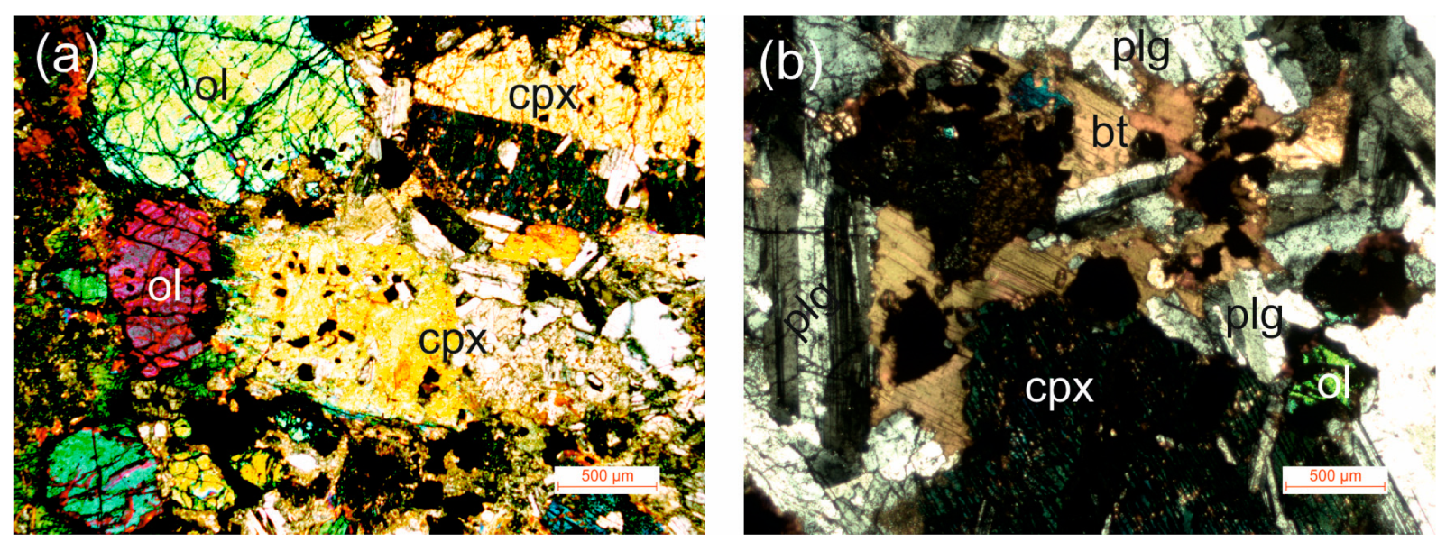
  • Lithological composition—the mineralogical composition of the rocks is a fundamental aspect to address in order to achieve the desired objectives. An expedited modal classification based on the relative percentage of mafic minerals (i.e., olivine, pyroxene, amphibole, and biotite) observed in thin sections was used to classify each massif into three classes, favoring those targets with the highest percentage of minerals enriched in calcium, magnesium, and iron.
  • Area—since data on subsurface geology in the study area are quite rare, the outcrop area is a relevant indicator for a first assessment of the size of the targets under study. In most cases, the mapped area corresponds to the outcrop area and can be estimated directly, but in cases where the unit under study is partially covered by more recent sediments, its determination is more difficult. Three classes were defined, and in situations of uncertainty, we always chose a conservative assessment.
  • Expected volume—the volume of rock masses was estimated by considering the previous criterion (area); the shape of each geological unit (stratiform or batholith); and, in some cases, any available geophysical information. As was the case for the previous criterion, in situations of uncertainty, a conservative assessment was always adopted.
  • Existence of a seal unit—the existence of an impermeable layer overlaying the target unit represents a particularly favorable structural situation, as this cover will act as a barrier to CO2 leakage for in situ mineral carbonation. The Carbfix project developed an injection method in which CO2 is injected dissolved in water, and thus CO2 buoyancy will not occur and the existence of a seal is not strictly necessary [11,28]. In Alentejo, the basal levels of tertiary deposits overlaying the Paleozoic and Mesozoic massifs generally correspond to impermeable clayey sediments. In the most favorable situations, where this tertiary coverage exists, a weight of 3 was assigned. In the remaining situations, where the formations crop out without any cover, or are covered by sands with Miocene age or later, a zero weight was assigned.
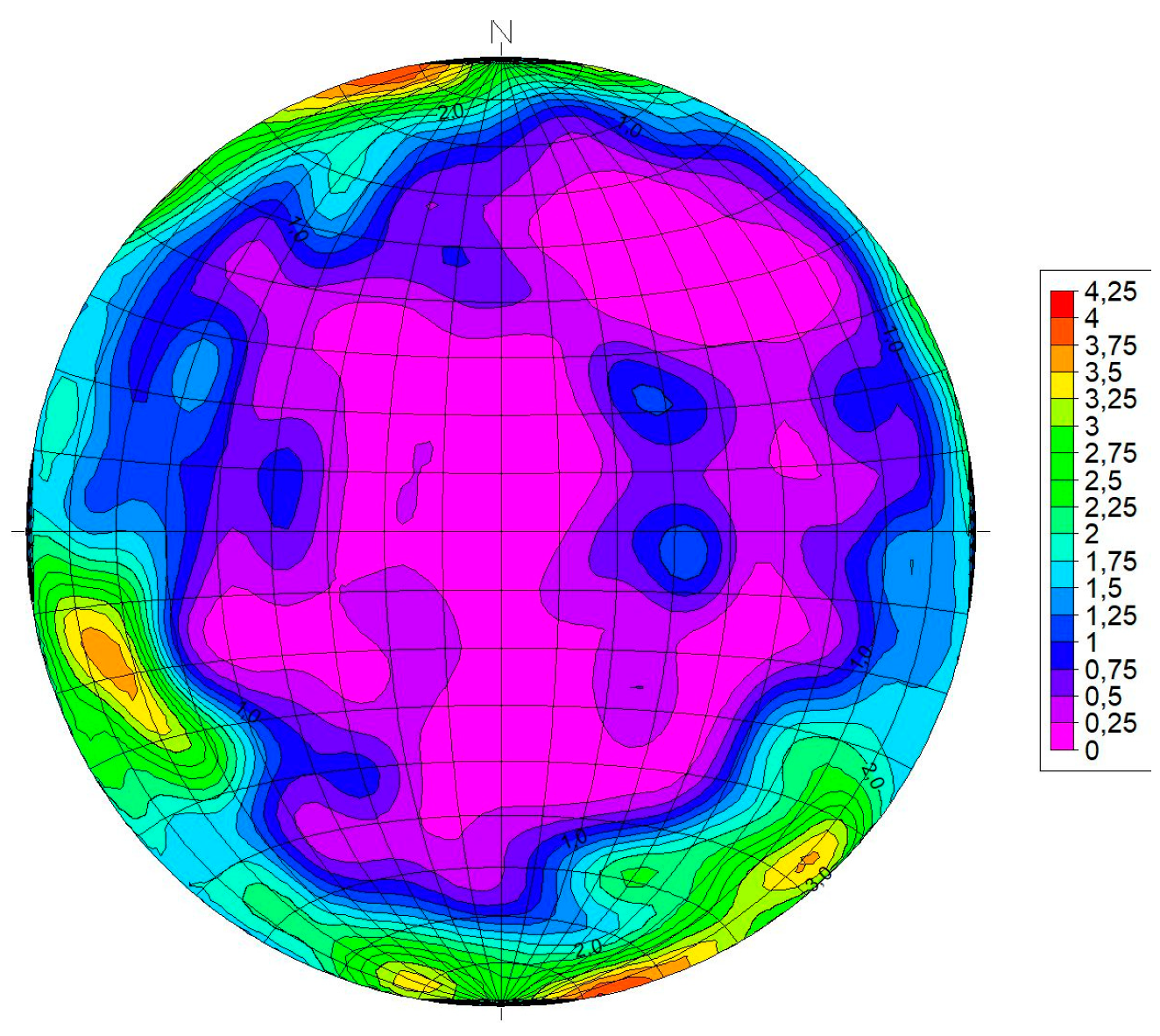
  • Fracture density—the main constraints when injecting fluids into plutonic rocks are low permeability and porosity. Fracture density controls the permeability and porosity of rock masses; a higher fracture density facilitates fluid circulation and thus in situ carbonation. For each geological formation, the fracture density was assessed by fracture pattern studies in outcrops and quarries using a scanline approach with measurement of fracture frequency. The massifs were divided into three categories: more than 10 fractures/m, 3–10 fractures/m, and fewer than 3 fractures/m, to which indices 9, 6, and 1 were assigned, respectively.
  • Socioeconomic and environmental constraints
6.
Distance to CO2 sources—transport of CO2 over long distances is a highly penalizing factor. Thus, for this criterion, three categories were defined as a function of the distance to which values 9, 6, and 1 were assigned, respectively, for distances of less than 10 km, between 10 and 100 km, and over 100 km.
7.
Social and demographic situation—building an industry for in situ carbonation will not be well accepted in urban areas. For this criterion, two categories were defined, wherein an index of 3 was assigned to rural regions and zero was assigned to urban areas.
8.
Existence of productive aquifers—groundwater is a value that must be preserved. Thus, geological units that correspond to productive aquifers were completely excluded on the basis of this criterion.
9.
Environmental restrictions—this type of project is prohibited in natural parks and other protected areas. This criterion was considered, but no geological formations favorable to in situ carbonation were identified in protected areas.
The final ranking of the rock massifs was obtained by adding the weights assigned to each criterion.

2.2. Petrographic, Mineral Chemistry, and Geochemical Techniques

The samples collected in the first field trip were processed in thin sections for petrography and mineral chemistry analysis and powdered for X-ray diffraction (XRD) and X-ray fluorescence (XRF) analysis (Figure 3).
The petrography included conventional petrographic techniques by transmitted and reflected light polarizing microscopy, complemented with scanning electron microscopy with energy-dispersive spectroscopy (SEM–EDS), which also provided a valuable semi-quantitative analysis of the mineral chemistry using a Hitachi S3700N interfaced with a Quanta EDS microanalysis system. The Quanta system was equipped with a Bruker AXS XFlash Silicon Drift Detector (129 eV Spectral Resolution at FWHM/MnKα). Standardless PB/ZAF (self-calibrating EDS spectrum procedure) quantitative elemental analysis was performed using Bruker Espirit software. The operating conditions for EDS analysis were 20 kV accelerating voltage, 10 mm working distance, and 120 μA emission current. The detection limits for major elements (>Na) were on the order of 0.1 wt %.
The petrographic analysis was also complemented by detailed identification of crystalline phases through XRD analysis using a Bruker AXS D8 Discover diffractometer with a Cu-Kα source, operating at 40 kV and 40 mA with a Lynxeye one-dimensional detector. Scans were performed from 3 to 75° 2θ, with a 0.05 2θ step and 1 s/step measuring time by point. Diffract-Eva Bruker software with PDF-2 database (Powder Diffraction File by the International Centre for Diffraction Data) was utilized to interpret all XRD patterns.
The whole rock geochemistry analysis was conducted by XRF, which allows for the quantification of major oxides (SiO2, TiO2, Al2O3, Na2O, K2O, CaO, MgO, MnO, FeO, and P2O5), sulfur, and some minor elements (Rb, Sr, Y, Zr, Nb, Th, Cr, Co, Ni, Cu, Zn, Ga, As, Pb, Sn, V, U, and Cl). Analyses were performed with an Energy-Dispersive X-Ray Spectrometer S2 Puma (Bruker) using a methodology similar to that adopted by Georgiou [29]. A description of the standard reference materials (SRM) utilized in the calibration method can be found elsewhere [30]. Samples were fused on a Claisse LeNeo heating chamber using a flux (Li-tetraborate) to prepare fused beads (ratio sample/flux = 1/10). The software utilized for acquisition and data processing was Spectra Elements 2.0, which reported the final oxide/element concentrations and the instrumental statistical error associated with the measurement.

3. Results

A first selection of several geological formations located in the Alentejo region (Figure 4) was made, which was considered potentially interesting due to their dimensions and lithological nature using the geological map of Portugal (scales 1/50,000, 1/200,000, and 1/500,000) and other general bibliographic elements.
Most of these units correspond to igneous, ultramafic, or mafic intrusive rocks of Paleozoic age (gabbros and diorites of Torrão‒Odivelas; Beja gabbros and igneous massifs of Alter do Chão/Cabeço de Vide, Veiros, Vale de Maceiras, Campo Maior, and Elvas). The Sines massif is also mostly composed by mafic rocks, but, having a Cretaceous age, is considerably more recent. The diabases from the Iberian Pyrite Belt are part of a Lower Carbonic volcano sedimentary complex and the ophiolitic sequences are mostly ultramafic and mafic rocks associated with the obduction of oceanic lithosphere during the Variscan orogeny.
For each of the 10 geological units represented in Figure 4, we determined the values corresponding to the nine criteria described. The sum of these values was used to rank the studied geological formations. Table 2 presents the result of these calculations and the hierarchy of the units in terms of their potentialities.
Among the studied units, two were eliminated due to lack of size (the Veiros massif and ophiolitic sequences because they are very fragmented), and two others were eliminated because they corresponded to productive aquifers (Beja gabbros and Alter do Chão/Cabeço de Vide massif).
Regarding the remaining six units, we emphasize the excellent rating achieved by the Sines massif, gabbros of Torrão‒Odivelas, and diabases from the Iberian Pyrite Belt. The Sines massif, which was ranked first and was selected for the first experiments, has the disadvantage of being located in an urban area, but the great advantage of its location near the CO2-producing sources and its extension for some kilometers into the continental shelf.
Further research is ongoing for the Sines and Torrão‒Odivelas massifs. The remainder of this article, as well as the article by Moita et al. [23] in this issue, address the works already conducted at the Sines massif.

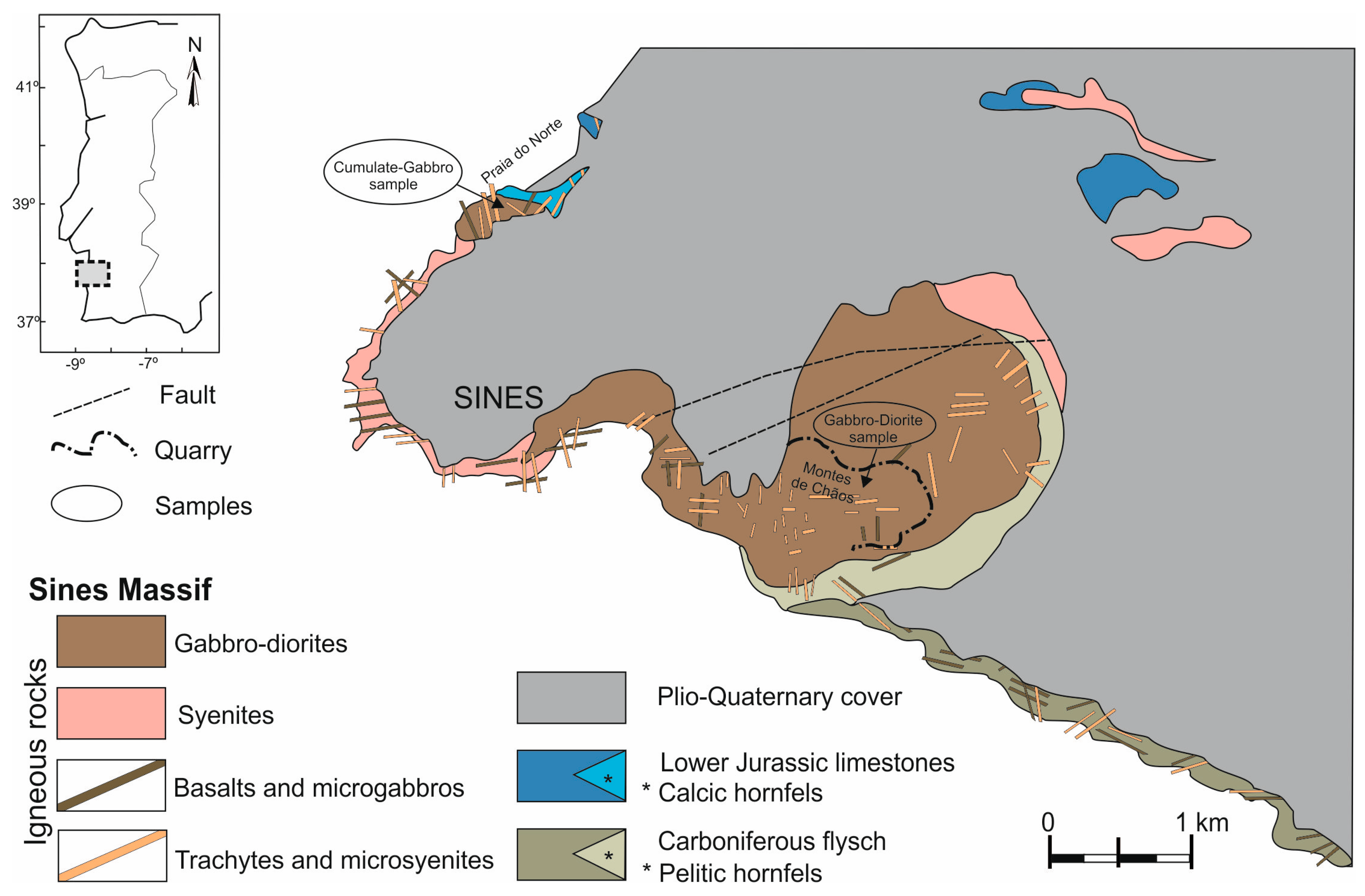
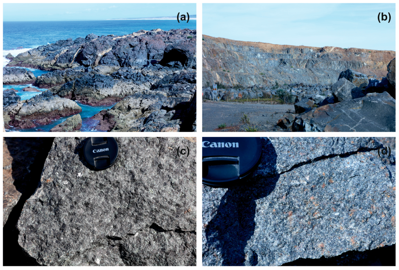
3.1. The Sines Massif

3.1.1. Geological Setting

The Sines massif (Figure 5) is located on the west Portuguese coast (southwest Iberia). Onshore it has a relatively small area (≈10 km2), largely covered by Plio-Quaternary sediments, mainly outcropping along the seacoast and in the Montes de Chãos quarry (Figure 6). It exhibits an elliptical shape that is elongated into the continental shelf and has been interpreted by Teixeira [31] and Ribeiro et al. [32] as a subvolcanic ring structure. Carvalho et al. [33], resorting to geophysical data (magnetic, gravimetric, and seismic reflection), were able to model the offshore of the massif, along a NE–SW trend, and covering an area of ≈300 km2.
Together with the Sintra and Monchique massifs, the volcanic complex of Lisbon, and several other minor intrusions, the Sines Massif is part of a Late Cretaceous alkaline magmatic cycle dated to ca. 22 Ma (94–72 Ma) [35].
The Sines massif is mainly formed of gabbros, diorites, and syenites, with a profusion of dykes of variable composition (basalts, microgabbros, microdiorites, trachybasalts, lamprophyres, trachytes, and microsyenites [34,36]). Despite the Cenozoic sedimentary cover, the geological map of Portugal at 1/50,000 scale (sheet 42-C, Santiago de Cacém [34]) shows that these intrusive rocks cut the Carboniferous flysch at the south (Mira Formation) and Lower Jurassic carbonate rocks at the north. A model of multiphase emplacement is accepted for the genesis of the Sines massif, with the intrusion of gabbro-diorite, followed by the intrusion of syenite, and finally the net of dykes that cut the intrusive massif rocks and the surrounding country rocks.

3.1.2. Fracture Characterization

In the field, the observed rocks of the Sines massif displayed very low primary porosity, as is expected for plutonic rocks. Therefore, the characterization of the fracture patterns is fundamental for an indirect assessment of the permeability of the massif and, consequently, for the viability of the gabbro and diorite being used for in situ mineral carbonation. The exposure at the walls of Montes de Chãos quarry is the best place to analyze the fracture patterns of the Sines massif. The obtained fracturing density diagram poles is shown in Figure 7.
For a more detailed fracture analysis, we performed several scanlines. This method consists of stretching a line along the walls of the quarry and measuring the intersection of the line with any discontinuity. To quantify the rock mass rating, we freely adapted the RQD (Rock Quality Designation) index, applied routinely to evaluate the fracture frequency in drill cores, which was calculated as the percentage of unfractured rock segments longer than 10 cm along the scanlines. That is, RQD was used here to quantify, along the scanlines, the percentage of consecutive fractures that were more than 10 cm apart. The scan lines and RQD results are listed in Table 3.
The data show a variety of orientations, which means it is not possible to establish a geometrically well-defined fracture pattern. The average spacing between fractures (10.7–24.5 cm) revealed a heterogeneous pattern with medium-density fractures, suggesting some secondary porosity, which increases the potential surface area available for reaction.
These results are consistent with those recently obtained by drilling cores in an internal report requested by the Administration of the Port of Sines [37], which states that the gabbro-diorite massif in general has good to excellent geotechnical quality, occasionally reasonable, especially in the most superficial areas of the massif. During the surveys carried out, the extraction of continuous rock cores without fractures was frequent, revealing the excellent geotechnical quality of the gabbro-diorite massif.

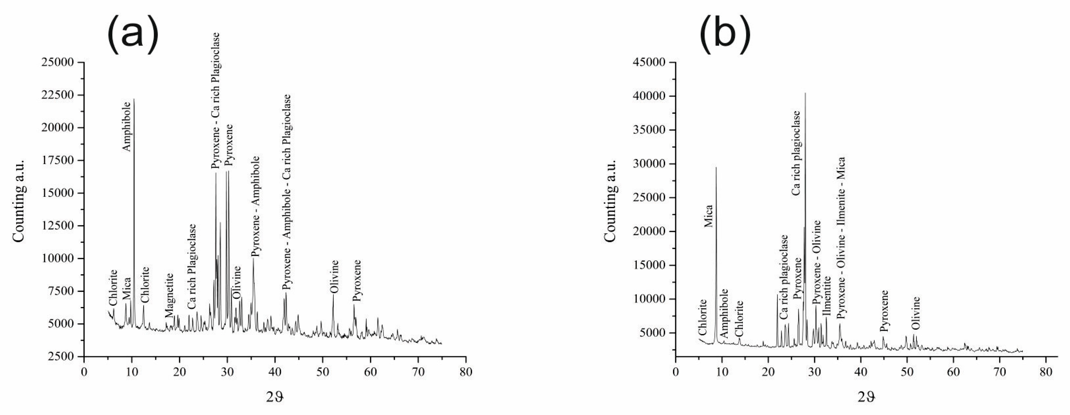
3.1.3. Petrography, Mineral Chemistry, and Geochemistry

Two coarse-grained ultramafic to mafic samples from the Sines massif were collected for laboratory characterization and mineral carbonation experiments—a melanocratic cumulate gabbro at a cliff near Praia do Norte (Figure 5 and Figure 6c) and a gabbro-diorite at Montes de Chãos quarry (Figure 5 and Figure 6d).
The cumulate gabbro sample displayed a medium to coarse igneous texture that preserved the ferromagnesian mineral phases. The mineral composition was found to be clinopyroxene (45–55%), olivine (15–20%), brown-amphibole (10–15%), plagioclase (5–10%), and primary ilmenite (5%) (Figure 8), although occasionally showed accessory alteration products (e.g., chlorite, actinolite, and serpentine). These secondary mineral phases occurred around the olivine, as well as around some pyroxene crystals. The enrichment in ferromagnesian minerals and their textural relations revealed cumulated textures, with amphibole crystals developing a poikilitic texture.
The mineral chemistry (Table 4) indicated the presence of magnesium olivines (Fo = 0.52–0.67), Ca–Fe–Mg clinopyroxenes with diopside–augite compositions, Ti-rich amphiboles (tschermakite horneblende), and calcic plagioclases with bytownite–labradorite compositions (An = 0.67–0.79). Except for ilmenite, which was not detected in the XRD diffractogram where the presence of magnetite was revealed, suggesting equilibrium at low temperatures in the oxide phases, we confirmed all primary mineralogy by XRD analysis (Figure 9). The rock geochemistry data (Table 5) showed very low SiO2 contents (42.3 wt %), compatible with an ultrabasic composition, and high MgO (12.90 wt %), CaO (12.7 wt %), Fe2O3 (15.15 wt %), Cr (478 ppm), and Ni (117 ppm). This compositional spectrum, coupled with a high value of TiO2 (3.34 wt %), agrees with the observed enrichment in ferromagnesian mineral and denotes magmatic alkaline features.
The gabbro-diorite sample exhibited a hypidiomorphic texture and was found to be composed of plagioclase (50–60%) and clinopyroxene (20–25%), and, to a lesser extent, olivine (5–10%), biotite (10–15%), and ilmenite (5–10%). The sample was heterogeneous, with plagioclase-enriched layers alternated with ferromagnesian-enriched layers. Despite some fractures with chlorite and incipient sericitization, the sample had no significant alteration.
The mineral chemistry data (Table 4) indicated a more evolved composition with ferrous olivines (Fo = 0.40–0.46), diopside–augite compositions for clinopyroxenes, slightly fewer calcium plagioclases (An = 0.61–0.72), ferromagnesium micas, and Fe-rich ilmenite. The XRD (Figure 9) and mineral chemistry (Table 4) data support the previous observed and analyzed mineralogy. The geochemical data revealed (Table 5) a basic composition (SiO2 = 49.00 wt %) and displayed lower MgO (4.48 wt %), CaO (8.33 wt %), and Fe2O3 (11.20 wt %), enhanced by low Cr (20 ppm) and Ni (7 ppm) and high Sr (748 ppm) values, which were directly related to the modal abundance of plagioclase, clinopyroxene, and olivine. The established basic composition and the TiO2 value (3.26 wt %) obtained for the gabbro-diorite agree with the values reported by Canilho [38].

4. Discussion

In general, according to Schaef et al. [39], Rosenbauer et al. [40], and Alfredsson et al. [41], the injection of carbon dioxide into basaltic rocks has several advantages in comparison with sedimentary basins if the storage of CO2 is through its mineral carbonation. Effective mineral carbonation of CO2 is best achieved with ultrabasic or basic volcanic rocks due to the high contents of Mg2+, Fe2+, and Ca2+ in ferromagnesian mineral phases, which can react with CO2 and precipitate as carbonates (e.g., magnesite, siderite, or calcite).
Since basalt carbonation could therefore become an important carbon storage solution [15], we selected 10 ultramafic and mafic rock areas in this study as a potential area for CO2 storage. In a preliminary phase of site characterization for CO2 geological storage in ultrabasic and basic volcanic rocks, we selected one geological formation with the potential to be considered as adequate for CO2 storage. Comparing the 10 studied areas, we found that the Sines massif had more favorable characteristics (Table 3) than the other areas with respect to all the relevant parameters evaluated (Table 2). Its location, only a few kilometers from the main CO2 sources in the region, which would avoid excessive transport costs, coupled with the large expected volume of cumulate gabbro with a high percentage of mafic minerals, provided the best prospect in the study area for the implementation of mineral carbonation projects.
Despite the subvolcanic (intrusive) nature of the Sines massif, the study of mafic lithologies, in particular the cumulate gabbros with more than 60% of ferromagnesian minerals, presented the chemical and mineralogical features theoretically required for mineral carbonation. Frequently, the boundaries between the cumulate gabbros and diorites were unclear, and thus it became necessary to test not only the more mafic lithologies but also the dioritic rocks in order to assess the mineral carbonation potential of the rock massif.
As such, samples of both rock types were tested in laboratory experiments to quantify their reactivity with a natural brine highly saturated with CO2, under supercritical conditions, to understand the chemical reactions that are expected to occur in the area immediately surrounding an injection well. These laboratory experiments were designed to assess whether the CO2–water–rock interaction would dissolve the cations of cumulate gabbros and gabbro-diorites necessary to react the CO2 and promote fast mineral carbonation.
The Sines massif is ideally located close to the CO2 sources in the region, which are hundreds of meters to a few kilometers away from the cumulate gabbros outcrops. A further advantage is that the subvolcanic massif extends from those outcrops to the offshore, where it encompasses a much larger area, most of which is covered by recent sediments. A scenario of CO2 injection in the cumulate gabbros in the near offshore could be used to assess whether the fracture permeability is sufficient to allow for injection. Geophysical surveys and reinterpretation of previous data were necessary to clarify the offshore area, volume, and fracture pattern. The studies of fracture density did not show a consistent and pervasive fracture pattern, and it is expected that fracture density decreases with depth, which may make an in situ carbonation process unviable.
Mineral carbonation can also be achieved ex situ by resorting to the mining of the cumulate gabbros in quarries and promoting its reaction with CO2 in specifically built facilities. A large quarry already exists in the Sines massif. Enhanced weathering is another possibility. The biggest contributor to the natural cycle of removing carbon dioxide from the atmosphere is the chemical weathering of certain types of rocks. This process is obviously very slow, but some studies (e.g., [22,23,24,25,26,27,28,29,30,31,32,33,34,35,36,37,38,39,40,41,42]) have demonstrated that, under the right conditions, the utilization of crushed mafic rocks could result in a net removal of CO2 from the atmosphere. The mineral carbonation experiments being conducted should indicate whether the cumulate gabbros and gabbro-diorites from the Sines massif have some potential for these applications.

5. Conclusions

Several outcropping mafic rock massifs in the south of Portugal may present an opportunity for mineral carbonation from the CO2 sources located in the region, which make up the largest industrial cluster in the country. The conditions of these rock massifs, composed primarily of plutonic rocks, are far from ideal in terms of porosity and permeability, and thus we adopted a set of ranking criteria to select the rock massifs that may present the highest potential. The adopted ranking criteria considered geological factors and socioeconomic and environmental constrains, with the most relevant being the percentage of mafic minerals, the fracture density, and the proximity to CO2 sources to minimize transport costs. Criteria such as exceptionally low expected volume, the existence of productive aquifers, and environmentally protected areas were eliminatory factors.
Application of the screening and ranking procedure allowed us to select, from the identified 10 ultramafic and mafic rock massifs in the study area, the two with the best conditions for mineral carbonation—the Sines massif and the gabbros from Torrão‒Odivelas massif.
The petrographic, mineral chemistry, and geochemical study of samples from the Sines massif demonstrated that the mineralogy of the cumulate gabbros is, theoretically, very favorable for mineral carbonation, with a higher percentage of ferromagnesian minerals than was previously documented. This has prompted mineral carbonation experiments in which the rock samples are submerged in a brine supersaturated in CO2, under pressure and temperature conditions enough to ensure supercritical CO2 conditions, in order to understand the CO2–brine–CO2 reactions. These experiments and their results are described in a second article [23].

Author Contributions

J.P., A.A.A., P.M., and J.C. were responsible for the selection of mafic and ultramafic massif rocks. J.P., A.A.A., P.M., M.B., L.L., and J.C. sampled the massif rocks. A.A.A. performed the ranking of massif rocks. J.P., A.A.A., P.M., L.L., A.C., and J.C. collected the geological and structural field data. J.P., P.M., and M.B. were responsible for sample preparation, petrography, mineral chemistry, and geochemical sample characterization. J.P., A.A.A., P.M., E.B., and J.C. interpreted the data and planned this paper. All the authors discussed the results and edited the manuscript. All authors have read and agreed to the published version of the manuscript.

Funding

This work was supported by national funds through the Portuguese FCT—Fundação Para a Ciência e Tecnologia—in the scope of project INCARBON, contract PTDC/CTA-GEO/31853/2017.

Acknowledgments

APS—Ports of Sines and the Algarve Authority, S.A. is gratefully acknowledged for cooperation on the collection of rock samples from the Monte Chãos quarry. We also would like to thank two anonymous reviewers for their constructive comments.

Conflicts of Interest

The authors declare no conflict of interest. The funders had no role in the design of the study; in the collection, analyses, or interpretation of data; in the writing of the manuscript; or in the decision to publish the results.

References

  1. IEA. Energy Technology Perspectives 2017: Catalysing Energy Technology Transformations; IEA/OECD: Paris, France, 2017. [CrossRef]
  2. UNFCCC. Adoption of the Paris Agreement—Proposal by the President; UNFCCC—United Nations Framework Convention on Climate Change: Paris, France, 2015; p. 31. [Google Scholar]
  3. APA. Roadmap for Carbon Neutrality 2050—Long-Term Strategy for Carbon Neutrality of the Portuguese Economy by 2050; Agência Portuguesa do Ambiente: Lisbon, Portugal, 2019; p. 102.
  4. European Commission. The European Green Deal. Communication from the Commission to the European Parliament, the European Council, the Council, the European Economic and Social Committee and the Committee of the Regions; European Comission: Brussels, Belgium, 2019; p. 24. [Google Scholar]
  5. Boavida, D.; Carneiro, J.; Martinez, R.; van den Broek, M.; Ramirez, A.; Rimi, A.; Tosato, G.; Gastine, M. Planning CCS Development in the West Mediterranean. Energy Procedia 2013, 37, 3212–3220. [Google Scholar] [CrossRef] [Green Version]
  6. Seixas, J.; Fortes, P.; Dias, L.; Carneiro, J.; Boavida, D.; Aguiar, R.; Marques, F.; Fernandes, V.; Helseth, J.; Ciesielska, J.; et al. CO2 Capture and Storage in Portugal: A Bridge to a Low Carbon Economy; FCT-UNL: Lisbon, Portugal, 2015; p. 42. [Google Scholar]
  7. EU ETS. European Union Emission Trading System—European Union Transaction Log. Available online: https://ec.europa.eu/clima/ets/oha.do (accessed on 2 December 2019).
  8. Carneiro, J.; Martinez, R.; Suaréz, I.; Zarhloule, Y.; Rimi, A. Injection rates and cost estimates for CO2 storage in the west Mediterranean region. Environ. Earth Sci. 2015. [Google Scholar] [CrossRef]
  9. Van den Broek, M.; Boavida, D.; Cabal, H.; Carneiro, J.; Fortes, P.; Gouveia, J.; Labriet, M.; Lechón, Y.; Martinez, R.; Mesquita, P.; et al. Report with Selection of Most Promising CCS Infrastructure Options. COMET Technical Note TN6.4; University of Utrech: Utrecht, The Netherlands, 2013; p. 173. [Google Scholar]
  10. Veloso, F.M.L. STRATEGY CCUS-Strategic planning of Regions and Territories in Europe for low-carbon energy and industry through CCUS Coordination and Support Action (CSA). In Proceedings of the CO2GEONET Open Forum, Venice, Italy, 6–9 May 2019. [Google Scholar]
  11. Matter, J.M.; Stute, M.; Snaebjornsdottir, S.O.; Oelkers, E.H.; Gislason, S.R.; Aradottir, E.S.; Sigfusson, B.; Gunnarsson, I.; Sigurdardottir, H.; Gunnlaugsson, E.; et al. Rapid carbon mineralization for permanent disposal of anthropogenic carbon dioxide emissions. Science 2016, 352, 1312–1314. [Google Scholar] [CrossRef] [PubMed] [Green Version]
  12. Zevenhoven, R.; Eloneva, S.; Teir, S. Chemical fixation of CO2 in carbonates: Routes to valuable products and long-term storage. Catal. Today 2006, 115, 73–79. [Google Scholar] [CrossRef]
  13. Goldberg, D.S.; Takahashi, T.; Slagle, A.L. Carbon dioxide sequestration in deep-sea basalt. Proc. Natl. Acad. Sci. USA 2008, 105, 9920–9925. [Google Scholar] [CrossRef] [Green Version]
  14. Andreani, M.; Luquot, L.; Gouze, P.; Godard, M.; Hoisé, E.; Gibert, B. Experimental Study of Carbon Sequestration Reactions Controlled by the Percolation of CO2-Rich Brine through Peridotites. Environ. Sci. Technol. 2009, 43, 1226–1231. [Google Scholar] [CrossRef]
  15. Gislason, S.R.; Oelkers, E.H. Carbon Storage in Basalt. Science 2014, 344, 373–374. [Google Scholar] [CrossRef]
  16. Druckenmiller, M.L.; Maroto-Valer, M.M. Carbon sequestration using brine of adjusted pH to form mineral carbonates. Fuel Process. Technol. 2005, 86, 1599–1614. [Google Scholar] [CrossRef]
  17. McGrail, B.P.; Spane, F.A.; Amonette, J.E.; Thompson, C.R.; Brown, C.F. Injection and Monitoring at the Wallula Basalt Pilot Project. Energy Procedia 2014, 63, 2939–2948. [Google Scholar] [CrossRef] [Green Version]
  18. Hanchen, M.; Prigiobbe, V.; Baciocchi, R.; Mazzotti, M. Precipitation in the Mg-carbonate system—Effects of temperature and CO2 pressure. Chem. Eng. Sci. 2008, 63, 1012–1028. [Google Scholar] [CrossRef]
  19. Romão, I.S.; Gando-Ferreira, L.M.; da Silva, M.M.V.G.; Zevenhoven, R. CO2 sequestration with serpentinite and metaperidotite from Northeast Portugal. Miner. Eng. 2016, 94, 104–114. [Google Scholar] [CrossRef]
  20. Sanna, A.; Uibu, M.; Caramanna, G.; Kuusik, R.; Maroto-Valer, M.M. A review of mineral carbonation technologies to sequester CO2. Chem. Soc. Rev. 2014, 43, 8049–8080. [Google Scholar] [CrossRef] [PubMed] [Green Version]
  21. Beerling, D.J.; Leake, J.R.; Long, S.P.; Scholes, J.D.; Ton, J.; Nelson, P.N.; Bird, M.; Kantzas, E.; Taylor, L.L.; Sarkar, B.; et al. Farming with crops and rocks to address global climate, food and soil security. Nat. Plants 2018, 4, 138–147. [Google Scholar] [CrossRef] [PubMed]
  22. Wu, J.C.S.; Sheen, J.-D.; Chen, S.-Y.; Fan, Y.-C. Feasibility of CO2 Fixation via Artificial Rock Weathering. Ind. Eng. Chem. Res. 2001, 40, 3902–3905. [Google Scholar] [CrossRef]
  23. Moita, P.; Berrezueta, E.; Abdoulghafour, H.; Beltrame, M.; Pedro, J.; Mirão, J.; Miguel, C.; Galacho, C.; Sitzia, F.; Barrulas, P.; et al. Mineral carbonation of CO2 in mafic plutonic rocks. II: Early-phase SC CO2-brine-rock interaction. Appl. Sci. 2020, 10, 5083. [Google Scholar]
  24. Bachu, S. Sequestration of CO2 in geological media: Criteria and approach for site selection in response to climate change. Energy Convers. Manag. 2000, 41, 953–970. [Google Scholar] [CrossRef]
  25. CO2CRC. Storage Capacity Estimation, Site Selection and Characterisation for CO2 Storage Projects; RPT08-1001; Cooperative Research Centre for Greenhouse Gas Technologies: Canberra, Australia, 2008; p. 52. [Google Scholar]
  26. NETL. Site Screening, Selection, and Initial Characterization for Storage of CO2 in Deep Geologic Formations. 2013 Revised Edition; DOE/NETL-2013/1605; National Energy Technology Laboratory: Pittsburgh, PA, USA, 2013; p. 110. [Google Scholar]
  27. Oldenburg, C. Health, Safety, and Environmental Screening and Ranking Framework for Geologic CO2 Storage Site Selection; LNBL: Sacramento, CA, USA, 2005; p. 22. [Google Scholar]
  28. Ragnheidardottir, E.; Sigurdardottir, H.; Kristjansdottir, H.; Harvey, W. Opportunities and challenges for CarbFix: An evaluation of capacities and costs for the pilot scale mineralization sequestration project at Hellisheidi, Iceland and beyond. Int. J. Greenh. Gas Control 2011, 5, 1065–1072. [Google Scholar] [CrossRef]
  29. Georgiou, C.D.; Sun, H.J.; McKay, C.P.; Grintzalis, K.; Papapostolou, I.; Zisimopoulos, D.; Panagiotidis, K.; Zhang, G.; Koutsopoulou, E.; Christidis, G.E.; et al. Evidence for photochemical production of reactive oxygen species in desert soils. Nat. Commun. 2015, 6, 7100. [Google Scholar] [CrossRef] [Green Version]
  30. Beltrame, M.; Liberato, M.; Mirão, J.; Santos, H.; Barrulas, P.; Branco, F.; Gonçalves, L.; Candeias, A.; Schiavon, N. Islamic and post Islamic ceramics from the town of Santarém (Portugal): The continuity of ceramic technology in a transforming society. J. Archaeol. Sci. Rep. 2019, 23, 910–928. [Google Scholar] [CrossRef]
  31. Teixeira, C. La structure annulaire subvolcanique des massifs éruptifs de Sintra, Sines et Monchique. In Est. Cient. Oferecidos em Homenagem ao Prof. Carrington da Costa; Junta de Investigação do Ultramar: Lisbon, Portugal, 1962; pp. 41–49. [Google Scholar]
  32. Ribeiro, A.; Antunes, M.T.; Ferreira, M.P.; Rocha, R.B.; Soares, A.F.; Zbyszewski, G.; Moitinho de Almeida, F.; Carvalho, D.D.; Monteiro, J.H.; Serviços Geológicos de, P. Introduction à la Géologie Générale du Portugal; Serviços Geológicos de Portugal: Lisbon, Portugal, 1979. [Google Scholar]
  33. Carvalho, J.P.G.; Torres, L.M.; Afilhado, A. Delimitação do maciço sub-vulcânico de Sines offshore a partir de dados geofísicos. Comum. Serv. Geol. Port. 1998, D57–D60. [Google Scholar]
  34. Inverno, C.; Manuppella, G.; Zbyszewski, G.; Pais, J.; Ribeiro, L. Notícia Explicativa da Folha 42-C Santiago do Cacém. Carta Geológica de Portugal de 1/50 000; Serviços Geológicos de Portugal: Lisbon, Portugal, 1993. [Google Scholar]
  35. Miranda, R.; Valadares, V.; Terrinha, P.; Mata, J.; Azevedo, M.d.R.; Gaspar, M.; Kullberg, J.C.; Ribeiro, C. Age constraints on the Late Cretaceous alkaline magmatism on the West Iberian Margin. Cretac. Res. 2009, 30, 575–586. [Google Scholar] [CrossRef] [Green Version]
  36. Canilho, M.H. Estudo geológico-petrográfico do maciço eruptivo de Sines. Bol. Mus. Lab. Min. FCUL 1972, 12, 77–161. [Google Scholar]
  37. GeoAlgar. Pedreira Monte Chãos Estudo Geológico-Geotécnico. Internal Report to APS (Administração do Porto de Sines); GeoAlgar: Sines, Portugal, 2019; p. 38. [Google Scholar]
  38. Canilho, M.H. Elementos de geoquímica do maciço ígneo de Sines. Ciências Da Terra UNL 1989, 10, 65–80. [Google Scholar]
  39. Schaef, H.T.; McGrail, B.P.; Owen, A.T. Carbonate mineralization of volcanic province basalts. Int. J. Greenh. Gas Control 2010, 4, 249–261. [Google Scholar] [CrossRef]
  40. Rosenbauer, R.J.; Thomas, B.; Bischoff, J.L.; Palandri, J. Carbon sequestration via reaction with basaltic rocks: Geochemical modeling and experimental results. Geochim. Cosmochim. Acta 2012, 89, 116–133. [Google Scholar] [CrossRef]
  41. Alfredsson, H.A.; Oelkers, E.H.; Hardarsson, B.S.; Franzson, H.; Gunnlaugsson, E.; Gislason, S.R. The geology and water chemistry of the Hellisheidi, SW-Iceland carbon storage site. Int. J. Greenh. Gas Control 2013, 12, 399–418. [Google Scholar] [CrossRef] [Green Version]
  42. Luckow, P.; Wise, M.A.; Dooley, J.J.; Kim, S.H. Large-scale utilization of biomass energy and carbon dioxide capture and storage in the transport and electricity sectors under stringent CO2 concentration limit scenarios. Int. J. Greenh. Gas Control 2010, 4, 865–877. [Google Scholar] [CrossRef]
Figure 1. (a) Distribution of main CO2 emissions sources in Portugal reported to the European Union carbon market database (EU ETS). The location of ultramafic and mafic rock massifs in the study area is shown in Figure 3. (b) Evolution of CO2 emissions in the study area and total national emissions from 2013 to 2018, as reported to the EU ETS. The sources in the target area were accountable for 44% of the CO2 emissions from power and industrial sources in the country in 2018. The Sines coal power plant is to be decommissioned in 2023, but the remaining sources in Sines and Setúbal will still be responsible for more than 30% of the emissions from the industrial sector in the country.
Applsci 10 04879 g001
Figure 2. Diagram illustrating the methodology employed to screen, rank, and characterize the rock massifs and rock samples. The samples were subsequently submitted to mineral carbonation experiments in the laboratory, the results of which are the subject of a second article [23].
Applsci 10 04879 g002
Figure 3. Diagram illustrating the sample processing and the analytical techniques used.
Applsci 10 04879 g003
Figure 4. Location of the studied units: (A) Variscan basement; (B) Mesozoic cover; (C) Cenozoic cover; (1) Sines massif; (2) diabases of the Iberian Pyrite Belt; (3) gabbros of the Torrão‒Odivelas region; (4) Beja gabbros; (5) ophiolitic sequences: (a) internal ophiolitic sequences; (b) Beja‒Acebuches ophiolitic complex; (6) Alter do Chão/Cabeço de Vide massif; (7) Veiros massif; (8) Vale de Maceiras massif; (9) Campo Maior massif; (10) Elvas massif.
Applsci 10 04879 g004
Figure 5. Geological map of Sines massif (adapted from Inverno et al. [34]) with sampling localities.
Applsci 10 04879 g005
Figure 6. Mesoscopic features of Sines massif at seacoast near Praia do Norte (a) and Montes de Chãos quarry (b). Detail of sampled cumulate gabbro at a cliff near Praia do Norte (c) and gabbro-diorite at Montes de Chãos quarry (d).
Applsci 10 04879 g006
Figure 7. Fracture density diagram poles for the Monte Chãos quarry, showing a great dispersion in the orientation of discontinuities. The projection uses the Schmidt equal area net, and the number of discontinuities represented is 425. The values in the scale represent the percentage of occurrence.
Applsci 10 04879 g007
Figure 8. Microphotographs of (a) cumulate gabbro and (b) gabbro-diorite under polarized light microscope. ol—olivine, cpx—clinopyroxene, plg—plagioclase, bt—biotite.
Applsci 10 04879 g008
Figure 9. XRD diffractograms of (a) cumulate gabbro and (b) gabbro-diorite.
Applsci 10 04879 g009
Table 1. Screening and ranking criteria. The shaded bars represent the relative importance of the class in each criterion. The final ranking results from the sum of the weight obtained in each criterion. If any massif was assigned the class “eliminatory criterion” it was not further considered in the screening and ranking procedure.
CriteriaClassesWeight
Geological conditions
C1Lithological compositionUltramafic—more than 90% of mafic minerals9Applsci 10 04879 i001
Mafic—40–90% mafic minerals6Applsci 10 04879 i002
Intermediate—10–39% of mafic minerals1Applsci 10 04879 i003
C2Outcropping areaOver 20 km23Applsci 10 04879 i004
From 10 to 20 km22Applsci 10 04879 i005
Less than 10 km21Applsci 10 04879 i003
C3Expected volumeOver 20 km36Applsci 10 04879 i002
From 10 to 20 km3 3Applsci 10 04879 i004
Less than 10 km3Eliminatory criterion
C4Existence of a seal unitExistent3Applsci 10 04879 i004
Not known0
C5Fracture densityMore than 10 fractures/m9Applsci 10 04879 i001
3–10 fractures/m 6Applsci 10 04879 i002
Fewer than 3 fractures/m1Applsci 10 04879 i003
Socioeconomic constraints
C6Distance to CO2 sourcesLess than 10 km9Applsci 10 04879 i001
From 10 to 100 km 6Applsci 10 04879 i002
Over 100 km1Applsci 10 04879 i003
C7Social and demographic situationUrban area3Applsci 10 04879 i004
Rural0
C8Existence of productive aquifersNo 3Applsci 10 04879 i004
YesEliminatory criterion
C9Environmental restrictionsNo restrictions 0
Protected areas Eliminatory criterion
Table 2. Ranking of ultrabasic and basic geological formations in the Alentejo region. A massif with an ideal condition would have a total score of 45.
CriterionC1 C2 C3C4 C5 C6 C7C8C9
Geological Formation
1—Sines massif63606900030
2—Diabases from Iberian Pyrite Belt12339630027
3—Gabbros of Torrão‒Odivelas63631630028
4—Beja gabbros6360113Elim0---
5—Ophiolitic sequences91Elim096300---
6—Alter do Chão/Cabeço Vide massif9360613Elim0---
7—Veiros massif61Elim011300---
8—Vale de Maceiras massif62301130016
9—Campo Maior massif63606130025
10—Elvas massif62306100018
Elim—eliminatory criterion.
Table 3. Scanline data, RQD (Rock Quality Designation) index, and scanline statistics. Latitude and longitude refer to the starting point of each scanline. Scanline 2* corresponds to the continuity of resuming observations along the same azimuth of scanline 2 after following 25 m of no collected data due to outcrop inaccessibility.
Scanline 1Scanline 2Scanline 2* Scanline 3
DataLength (cm)127512505902630
Latitude37.94978°37.9514°37.94924°
Longitude−8.85078°−8.84634°−8.84187°
Azimuth70°60°135°
Number of discontinuities636266153
Discontinuities per m4.95.011.25.8
Length of section between two consecutives fractures (cm)Average24.524.510.710.7
Standard deviation20.723.211.011.0
Maximum value1031205757
Minimum value4311
Sum of sections > 10 cm11671150373373
RQD (%)91.592.063.263.2
Table 4. Mineral chemistry by scanning electron microscopy with energy-dispersive spectroscopy (SEM–EDS) in atomic percent (at %).
at %Cumulate Gabbro
Olivine
n = 5
Pyroxene
n = 3
Amphibole
n = 4
Plagioclase
n = 4
Ilmenite
n = 2
MinMaxMinMaxMinMaxMinMaxMinMax
O61.56763.64660.44061.00759.76460.79762.56265.07361.71161.529
Si10.76411.85515.94116.56612.31312.98613.90414.8140.8040.600
Tin.d.n.d.0.3500.4391.6371.771n.d.n.d.15.83316.344
Al0.1000.6181.7441.9745.2045.54012.92214.3200.5340.840
Mg12.84417.5648.3828.8337.5607.860n.d.n.d.1.3212.518
Fe8.74111.9142.5652.8493.7263.938n.d.n.d.19.11517.567
Ca0.2070.3667.9208.8695.1905.4705.1616.5620.2750.215
Mn0.0000.2220.0000.1330.0000.129n.d.n.d.1.3210.383
Nan.d.n.d.1.0561.1222.1242.3901.6612.558n.d.n.d.
Kn.d.n.d.n.d.n.d.0.5240.5840.0000.295n.d.n.d.
Ca/(Ca + Na) 0.670.79
Mg/(Mg + Fe)0.520.67
at %Gabbro-Diorite
Olivine
n = 3
Pyroxene
n = 4
Biotite
n = 3
Plagioclase
n = 4
Ilmenite
n = 2
MinMaxMinMaxMinMaxMinMaxMinMax
O57.79658.84458.34658.90055.76258.68659.42061.24058.26560.052
Si11.84612.42916.45617.47212.62414.34818.24019.4202.4121.765
Tin.d.n.d.0.4500.5711.8012.563n.d.n.d.8.19916.736
Al0.4161.4291.6142.0206.9757.95311.05012.1401.6110.656
Mg11.29812.6128.7179.0516.6898.348n.d.n.d.2.0071.685
Fe14.93316.9373.2373.6175.6266.764n.d.n.d.26.59418.319
Ca0.2130.4268.1119.361n.d.n.d.3.9605.2200.5980.272
Mn0.3750.4460.1300.160n.d.n.d.n.d.n.d.0.3140.514
Nan.d.n.d.0.9821.1321.0051.6391.6332.530n.d.n.d.
Kn.d.n.d.n.d.n.d.4.5234.5470.2700.390n.d.n.d.
Ca/(Ca + Na) 0.610.72
Mg/(Mg + Fe)0.400.46
n—number of analyses; n.d.—not determined.
Table 5. Geochemical data in weight percent (wt %) and parts per million (ppm).
Cumulate GabbroGabbro-Diorite
wt %Stat Errorwt %Stat Error
SiO242.30±0.034449.00±0.0356
TiO23.34±0.01753.26±0.0176
Al2O39.40±0.029516.20±0.0368
Fe2O315.50±0.013311.20±0.0115
P2O50.28±0.004270.85±0.00506
MnO0.40±0.0050.32±0.005
MgO12.90±0.05064.48±0.0349
CaO12.70±0.04288.33±0.0375
BaO0.23±0.0130.28±0.013
Na2O0.84±0.05193.46±0.0607
K2O0.19±0.03451.42±0.0395
LOI0.89-0.03-
Total98.97-98.83 -
ppm ppm
S1900±17.21500±16.2
Rb9±2.0840±2.24
Sr286±2.57748±3.09
Y15±2.3034±2.46
Zr80±2.82199±3.14
Nb20±2.5262±2.65
Th9±2.9410±3.10
Cr478±29.020±25.4
Co198±5.65139±5.02
Ni117±4.127±3.42
Cu62±4.8242±4.88
Zn103±6.07108±6.37
Ga14±4.3025±4.67
As7±4.298±4.53
Pb0±012±17.2
Sn7±27.30±0
V479±68.0323±68.0
U0±0.2092±0.221
Cl43±0.36453±0.359

