Article

Valorization of Slags Produced by Smelting of Metallurgical Dusts and Lateritic Ore Fines in Manufacturing of Slag Cements

by
Theofani Tzevelekou
1,
Paraskevi Lampropoulou
2,*,
Panagiota P. Giannakopoulou
2,
Aikaterini Rogkala
2,
Petros Koutsovitis
2,
Nikolaos Koukouzas
3 and
Petros Petrounias
2
1
Laboratory of Metallurgy (METLAB), Department of Chemical Engineering, University of Patras, 26504 Patras, Greece
2
Section of Earth Materials, Department of Geology, University of Patras, 26504 Patras, Greece
3
Chemical Process & Energy Resources Institute, Centre for Research & Technology Hellas (CERTH), 15125 Maroussi, Greece
*
Author to whom correspondence should be addressed.
Appl. Sci. 2020, 10(13), 4670; https://doi.org/10.3390/app10134670
Submission received: 2 June 2020 / Revised: 2 July 2020 / Accepted: 4 July 2020 / Published: 7 July 2020

Abstract

:

Featured Application

Τhe smelting process can be applied for the direct recycling of the nickel ferrous dust collected in the gas cleaning systems of the rotary kilns (R/Ks) during the pre-reduction of laterite ore in the course of ferronickel production by the pyrometallurgical route. The method can also be applied for smelting of ore fines. Contained Ni is recovered in the liquid metal resulting in the production of high purity low Ni-alloyed steel grades following secondary metallurgical treatment. The composition of the produced slags by this method can be efficiently adjusted so that the slags could be used in the manufacturing of special slag type composite cements substituting clinker. Present findings indicate that there is also potentially space for improvement in conventional EAF steel slags composition to allow for their wider use in building sector. In general, the developed zero residues recycling process concept can be applied for the recycling of metallurgical wastes/byproducts (dusts, fines etc.) by “one-stage” reduction smelting in DC-arc furnaces without any pretreatment (agglomeration, briquetting, sintering) recovering the contained valuable metals in the liquid bath, while producing slags suitable for further utilization in the manufacturing of high added value environmental friendly building materials (cements) accountable for less CO2 footprint; relative to the amount of clinker being substituted.

Abstract

A pyrometallurgical process was developed for the recycling of Ni bearing dusts and laterite ore fines by direct reduction smelting in DC (direct current) arc furnace. In the course of the performed industrial trials, besides the Ni-recovery in the liquid bath, slag composition was deliberately adjusted in order to produce a series of metallurgical slags with different chemical and mineralogical composition. The aim of this study was to investigate their suitability as clinker substitute in cement manufacturing. Examined parameters were slag FeOx content, basicity and applied cooling media (air, water cooling). A series of composite Portland and slag cements were manufactured in laboratory scale incorporating 20% and 40% of each slag, respectively; the rest being clinker of OPC (ordinary Portland cement) and 5% gypsum. The extended mineralogical analysis and microstructural properties of the produced slags were examined and correlated with the properties of the produced cements. The physical and mechanical characteristics of all examined cement products were found to meet the requirements of the regulation set for cements. The present research revealed that the most critical parameter in the compressive strength development of the slag cements is the mineralogical composition of the slag. Even in cases where rapid cooling to obtain glassy matrix is not feasible, adjustment of slag analysis to obtain mineralogical phases similar to those met in clinker of OPC, even at higher FeO contents (up to ~21wt.%), can result in production of slag with considerable latent hydraulic properties. These results indicate that there is potentially space for adjustments in conventional EAF (electric arc furnace) steel slags composition to allow for their wider use in cement manufacturing with significant environmental and economic benefits resulting from the reduction of energy requirements, CO2 emissions and natural raw materials consumption.

1. Introduction

Electric arc furnace (EAF) steelmaking has been proven a promising recycling route for a variety of industrial, mining and metallurgical wastes enabling the recovery of contained metals in the produced steel products, while exploiting their chemical and/or energy content [1,2,3,4,5,6,7]. Technological advancements in auxiliaries, such as hollow graphite electrode in direct current (DC)-arc furnaces, special tuyères and manipulator lances have enabled further the efficient recycling of powder waste materials, as well as the feeding of fluxes and carbonaceous reductants along with carrier and process gases, allowing overall high recovery yield of valuable metals in the liquid bath [4,8,9]. In modern steelmaking furnaces these “redox-tools” also provide the ability to adjust the slag chemistry at request, so that, besides favoring the metallurgical yield of the process, it may well become appropriate for further utilization, as a secondary raw material in the production of high added value products. Slag valorization capability depends on its chemical and mineralogical composition resulting from the originating production process and applied cooling methodology. Generally, knowledge of the chemical, mineralogical, and morphologic characteristics of ferrous slags is essential, because their cementitious and mechanical properties, which play the key role in their utilization, are closely related to these features. For example, the properties in abrasion and attrition of steel slag are influenced by its morphology and mineralogy. Similarly, the volumetric stability of steel slag is a function of its chemistry and mineralogy. The most well established valorization case of ferrous slags is the utilization of Ground-Granulated Blast-Furnace slag (GGBS or GGBFS) as a substitution of clinker in cement manufacturing. Besides the conservation of natural resources, this substitution results in significant reduction of CO2 emissions per ton of produced cement, relative to the amount of clinker being substituted. In general, the production of 1.0 t of Portland cement causes 0.8–1 t CO2, while indicatively 1.0 t of slag cement containing 75% of GGBS causes emission of only 0.3 t CO2 [10,11]. These data include the calcination process, emissions from fossil fuel burning and the use of electricity.
For the case of EAF slag, its properties render it a good candidate for many engineering applications, including as a (heavyweight) aggregate for concrete, as radiation-shielding concrete, as an environmentally friendly substitute of natural aggregates such as barite, hematite or limonite [12]. Nevertheless, although the approach of EAF slag utilization in the final stage of cement manufacturing as clinker substitute similar to the exploitation of blast furnace slag has been limited researched [13,14,15] it has not been usually practiced, mostly due to its weak hydraulic properties [16]. Further, steel slag is not currently included in the European Norm in force for the types of cements [17]. Other hindering reasons, also constraining its direct wide use in concrete, are volume instability and potential swelling attributed to hydroxylation and subsequent carbonation of their free CaO and MgO contents [18,19,20], long-term oxidation of metallic iron from divalent to trivalent valence, as well as the transformation of β-C2S (2CaO·SiO2) to γ-C2S [12]. Finally, an environmental factor that has been discouraging in using some steel slags in constructions is the potential leaching of undesired metals over the life time of each construction application; however, this risk is particularly relevant for slags from stainless steel production [12]. Hot stage slag engineering aiming to influence slags chemical composition to enable higher value-added applications and energy recuperation has been gaining attention in the vision for sustainable metallurgy [21,22,23]. The improvement of the EAF slag cementitious properties by adjusting its chemical and mineralogical composition during the smelting and cooling periods, while maintaining a positive impact on the quality of produced metal, could potentially widen its use in construction sector, overcoming the aforementioned obstacles. In this direction, to tackle leachability issues, additions of bauxite, Al2O3 containing residues and aluminum metal as a method to increase the stability of stainless steel EAF slags and to stabilize chrome (Cr) was suggested by Mudersbach et al. [24], while Primavera et al. [25] has described the addition of a stabilizer oxide in the treatment of electric arc furnace (EAF) slags. However, studies for optimized EAF-slag, the primary targeted use remains as an aggregate in construction applications i.e., road bed. This use, even it is quite beneficial, does not maximize the value added benefits for the steel manufacturer. Preferably, its successful use in cement manufacturing as clinker substitute should upgrade its added value in the circular economy chain, yield important environmental and economic benefits for both steel and cement industry, contribute to the conservation of natural resources, as well as to further reduction of CO2 emissions in cement industry, by expanding the cycle of alternatives to clinker secondary raw materials [19,26].
A reduction smelting process was developed for the efficient recycling of metallurgical Ni-bearing dust by injection through the hollow electrode in DC—EAF [4,27,28]. This dust is collected in the gas cleaning systems of the rotary kilns (R/Ks) during the pre-reduction of laterite ore in the course of ferronickel production by the pyro-metallurgical route. This method can also be applied for the smelting of ore fines; their collection and treatment prior to their feeding in the R/Ks will considerably reduce the amount of generated dust. A significant advantage of the developed process in the DC-arc furnace is that it allows the direct smelting of the fine materials without any pretreatment (agglomeration, briquetting, sintering) [4,8]. During the industrial testing of the process, apart from the effective dust and ore fines recycling and nickel recovery in the metal, the interest was also focused on the production of different steel slag types in terms of chemical and mineralogical composition. The objective of the present research was to investigate their suitability as clinker substitute in common cement manufacturing and further the correlation of the obtained results to the microstructural characteristics of the used slags, to establish the development of a zero residues production melting process for metallurgical dusts and ore fines recycling as presented to the flow sheet in the corresponded supplementary file. Examined parameters were slag FeOx content, basicity and applied cooling media (air, water cooling). A series of cements incorporating 20% and 40% of each slag respectively were manufactured in laboratory scale. Since the current European Norm [17] for common cements refers only to the utilization of ground granulated blast furnace slag (GGBS) in cement production, the physical and mechanical characteristics of the manufactured cements in the present study have been compared to the requirements for composite Portland cements with blast furnace slag (CPCs) and slag cements (SCs) for the mixtures with 20% and 40% slag content, respectively. The main difference is that blast furnace slag accepted in cement production according to EN 197-1 [17], contains at least two-thirds by mass of glassy slag and has minimum iron oxide content.

2. Materials and Methods

2.1. Tests in Raw Materials

Industrial reduction smelting trials for the recycling of Ni-bearing dust and laterite fines have been conducted in DC–EAF furnace with very high Ni-recovery in the produced metal, as described in [4], where the furnace installation, the data of conducted industrial trials and their metallurgical evaluation have been thoroughly analyzed. The liquid metal following secondary metallurgical treatment resulted in the production of low nickel alloyed steel grades [4]. Typical chemical analysis of the most important constituents of the dust and ore fines is presented in Table 1, while their detailed characterization including mineralogical and microstructural analysis by XRD, SEM/EDS and grain size distribution can be found in [4,28]. Slag chemistry adjustment was carried out during the trials in order to produce slags with desired range of chemical composition. The slag analysis was deliberately influenced by proper fluxes and reductants additions during the smelting campaigns, as described in [4,26,28]. The selected slag parameters examined were the FeOx content, the basicity of the slags expressed as CaO/SiO2 (wt.%/wt.%) and the effect of slag cooling procedure (air or water cooling).The objective was to investigate the effect of these parameters on the slags utilization as clinker substitute in the production of slag containing cements. This was achieved by pre-calculated additions of reducing agents and fluxes; namely, carbon and metallurgical lime, respectively. Having the targeted use in mind, addition of dolomitic lime was avoided in order not to increase slags MgO content and also for promoting FeOx reduction. Two different means of slag cooling were also applied: (a) air by tapping liquid slag in a pit in the plant yard and leave it to cool and (b) water by purring liquid slag in a basket filled with water. In total, nine different slags were collected.
The chemical analysis of the slags was determined by X-ray fluorescence, XRF. The mineralogical analysis of the slags were determined by powder X-ray diffraction (XRD), using a Bruker D8 Advance diffractometer (Bruker, Billerica, MA, USA), with Ni-filtered CuKα radiation. The scanning area for bulk mineralogy of the samples covered the 2θ interval 20–70°, with a scanning angle step size of 0.015° and a time step of 0.1 s. The mineral phases were determined using the DIFFRAC plus EVA 12® software (Bruker-AXS, Billerica, MA, USA) based on the ICDD powder diffraction file of PDF-2 2006. Study of the slags microstructure was carried out by Scanning Electron Microscopy (SEM) (JEOL JSM-6300), while several microanalyses were performed with Energy Dispersive X-ray Spectroscopy (SEM/EDS).

2.2. Tests in Cement Production

A series of composite Portland and slag cements were manufactured in laboratory scale by co-grinding 20% and 40% of each slag, respectively with clinker of ordinary Portland cement (OPC). In all cement mixtures 5% gypsum was used and the remaining mass was clinker of OPC. Reference OPC (95% clinker, 5% gypsum) mixtures were also manufactured for comparison purposes. The experimental procedure involved separate crushing of the slag and the clinker, so that 95% is below 5 mm. The crushed materials were mixed with gypsum in the aforementioned ratios and subsequently co-ground in a 5-kg ball mill until targeted specific surface (Blaine) of 4500 cm2/g was achieved. Indicatively two cements incorporating 20% slag but targeting to lower Blaine of 3650 cm2/g were also comparatively manufactured along with corresponding reference OPC. Once grinding was completed, proper specimens were prepared for the determination of the experimental cement’s technological properties according to the corresponding standards specified in EN 197-1 [17], the standard in force for cement products. Initial and final setting time, expansion and early, late and long-term compressive strengths up to 90 days of hydration were measured.
In the final step of this study, co-evaluation of the results was performed and correlations between the mineralogical analysis and microstructural properties of the produced steel slags with the physical and mechanical characteristics of the produced cements were acknowledged. Since the European Norm in force for the types of cements [17] refers only to the utilization of GGBS in cement production, experimental cements classification was made indicatively following the corresponding ranges described in [17] for blast furnace slags. The obtained results of this research are hereafter presented and discussed.

3. Results and Discussion

3.1. Slags Characterization

3.1.1. Chemical Composition

The chemical composition of the so produced slags in wt.% used for cements manufacturing and the mean of their cooling are presented in Table 2. Due to the applied experimental conditions of the trials [4,28], iron is expected to be mainly in divalent state in slags 3 and 4, while higher trivalent iron content is present in slag 5. Accordingly, higher fraction of Cr should be expected to be divalent than trivalent form due to the highly reducing conditions of the smelting process [28,29]. The lowest FeO content in slags 4-2 was achieved by aluminum addition during smelting via the aluminothermic reduction reaction 3(FeO) + 2 [Al] = Al2O3 + 3 [Fe], increasing also the Al2O3 content of the slags.

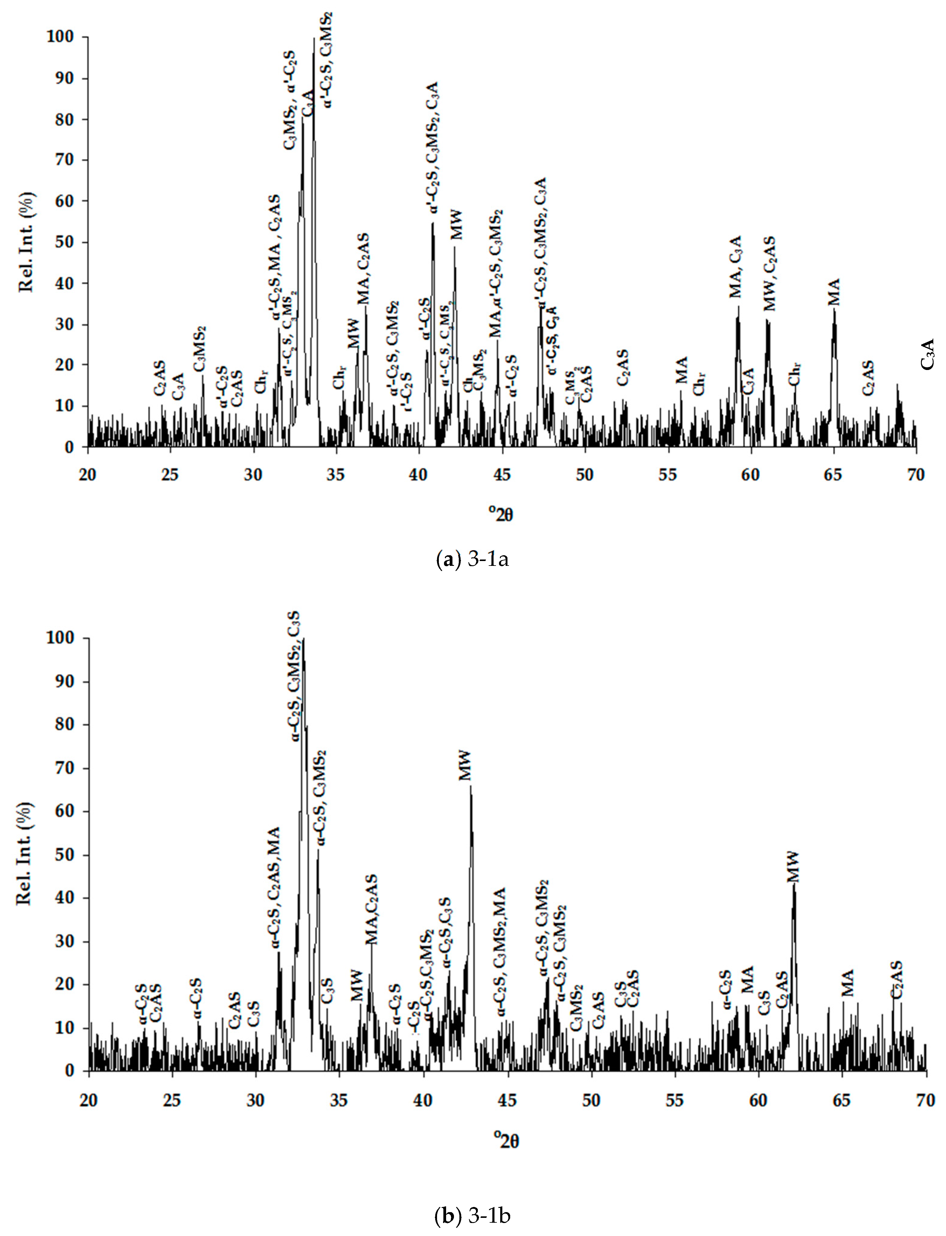
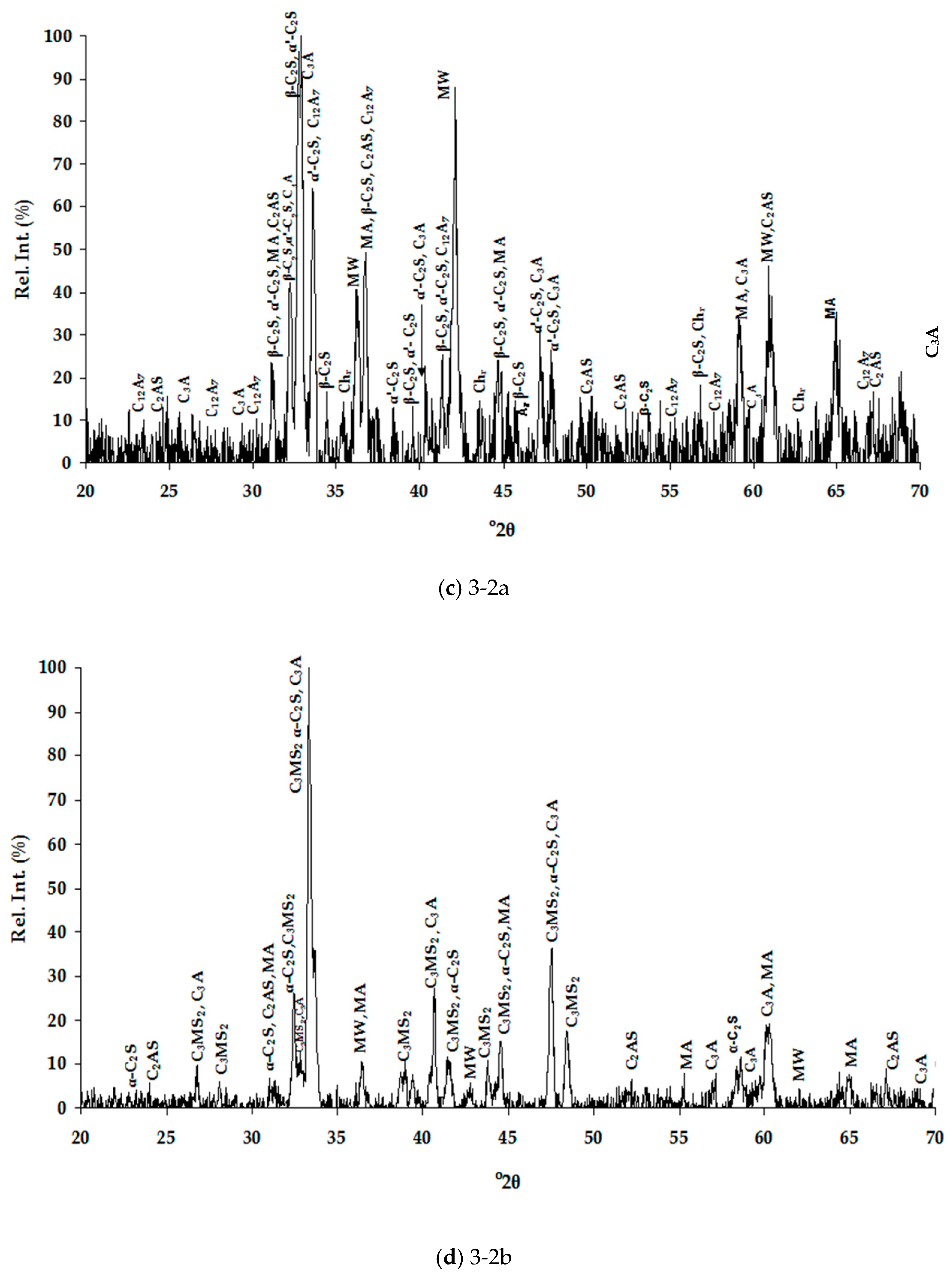
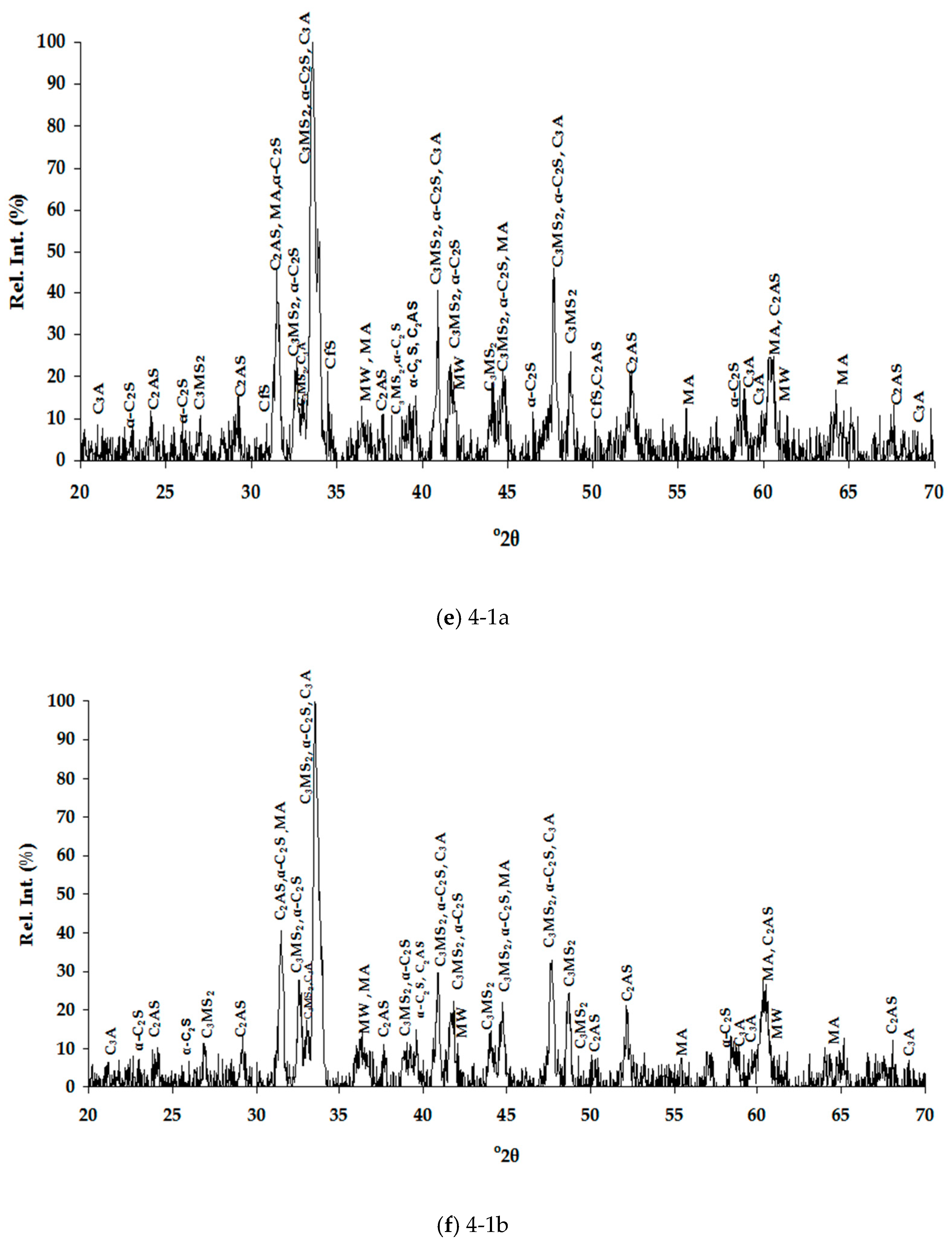
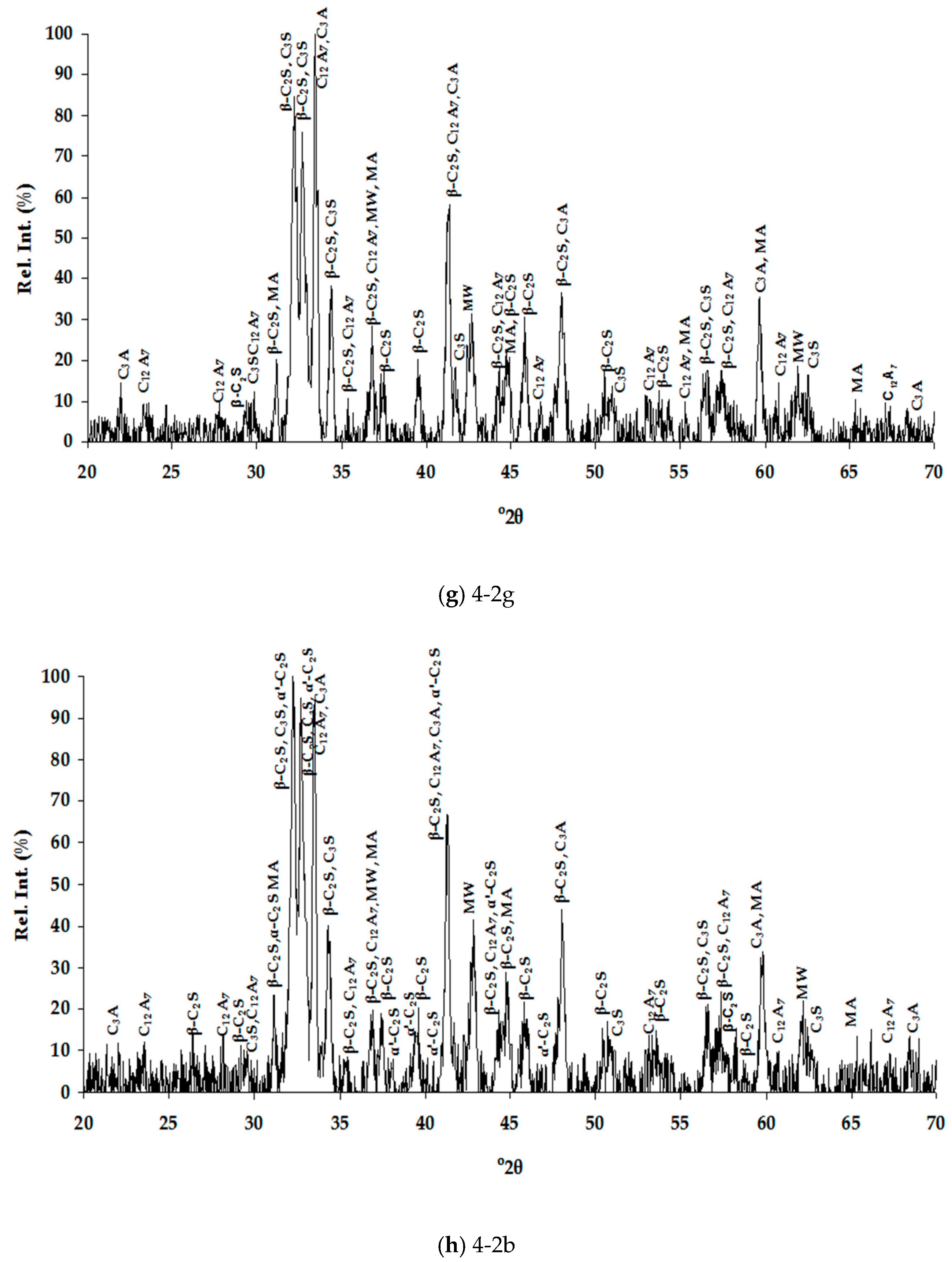
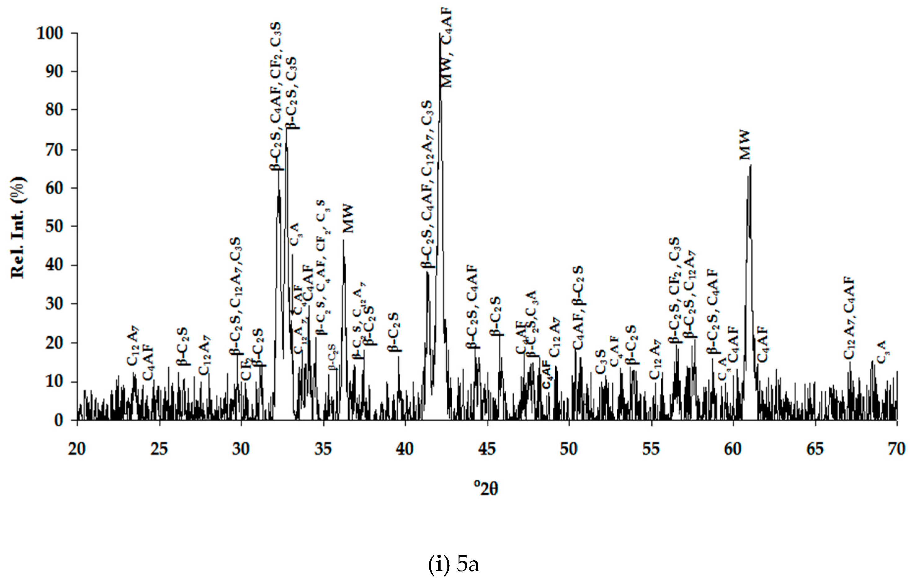
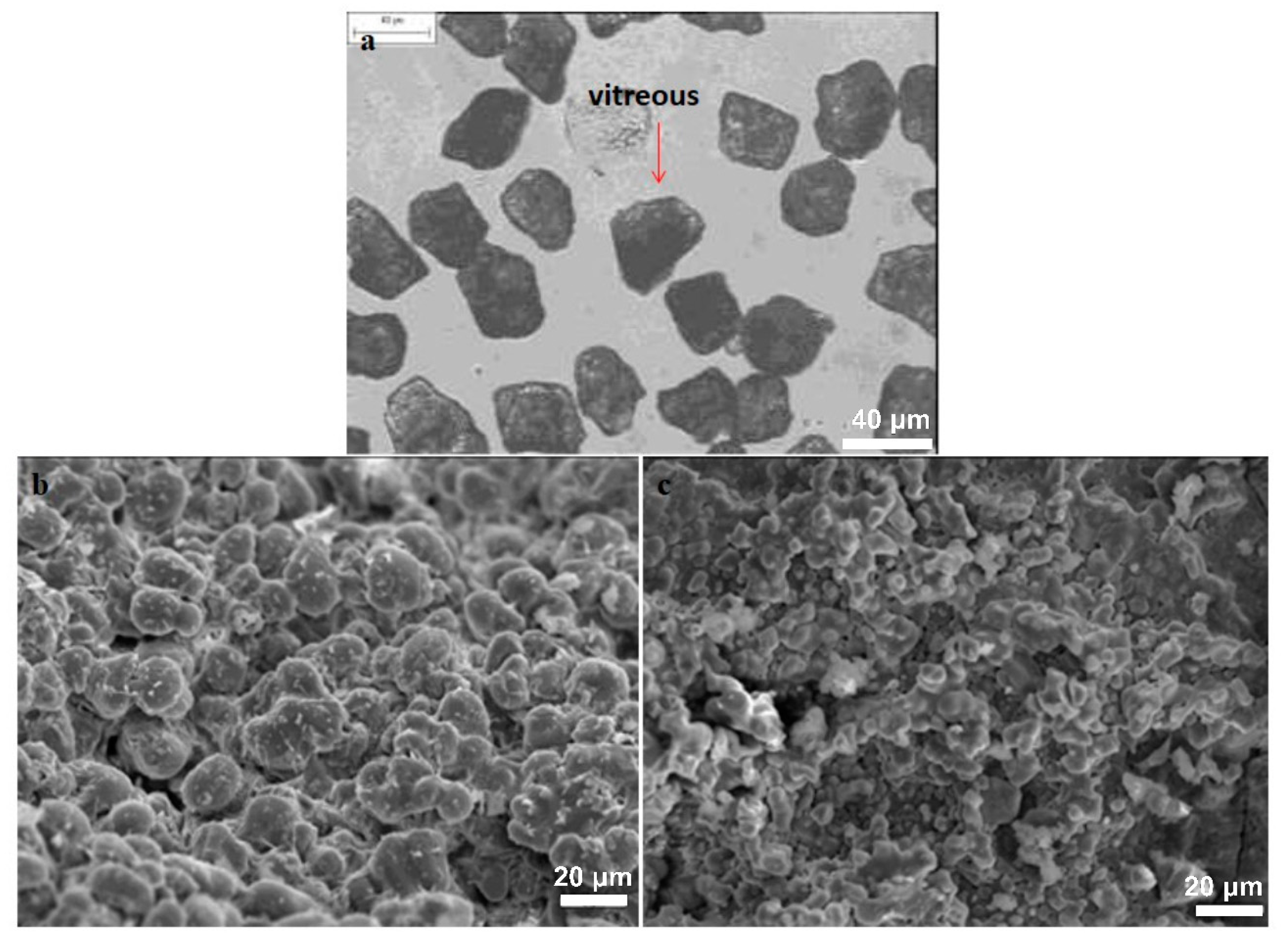
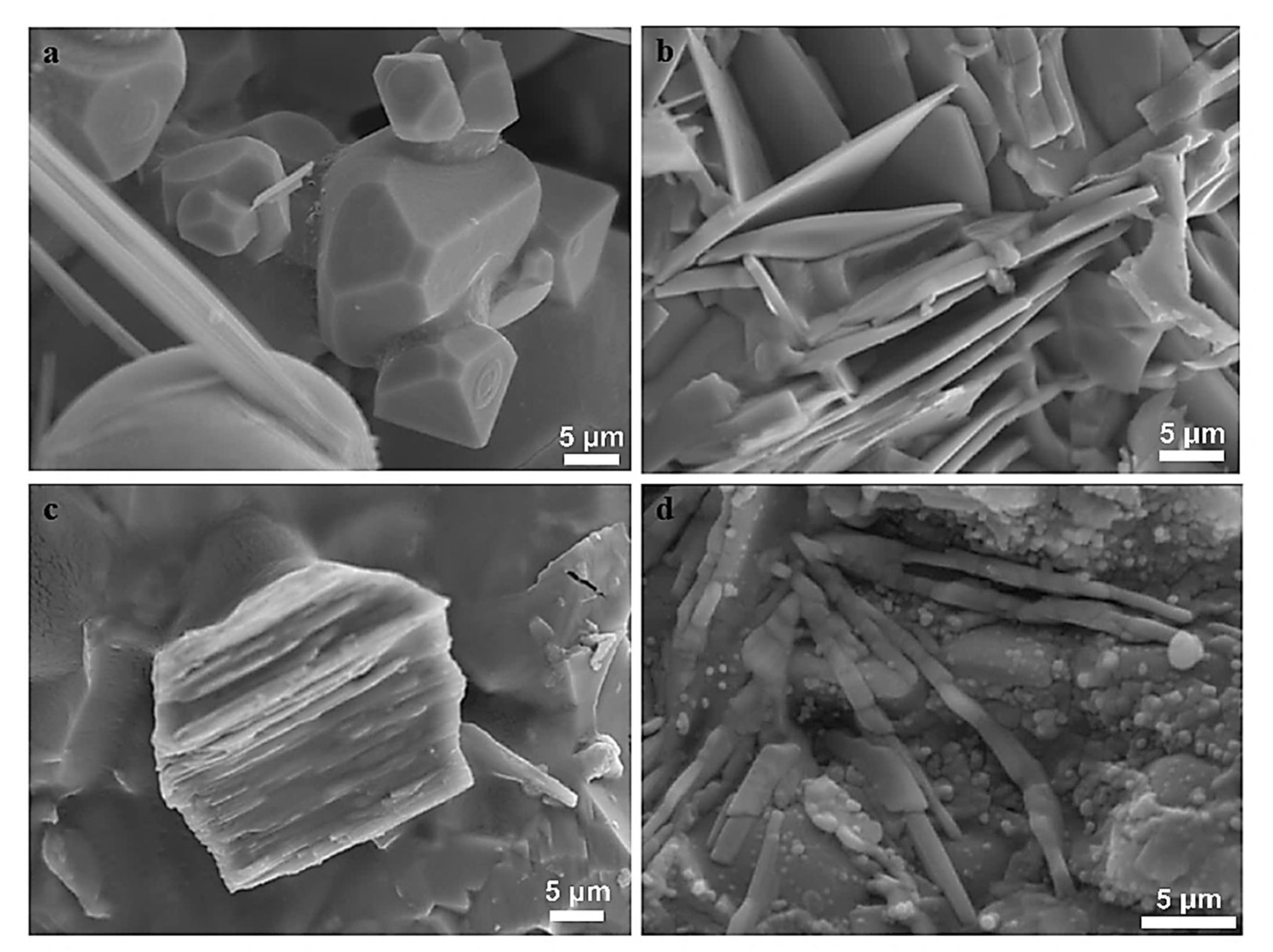
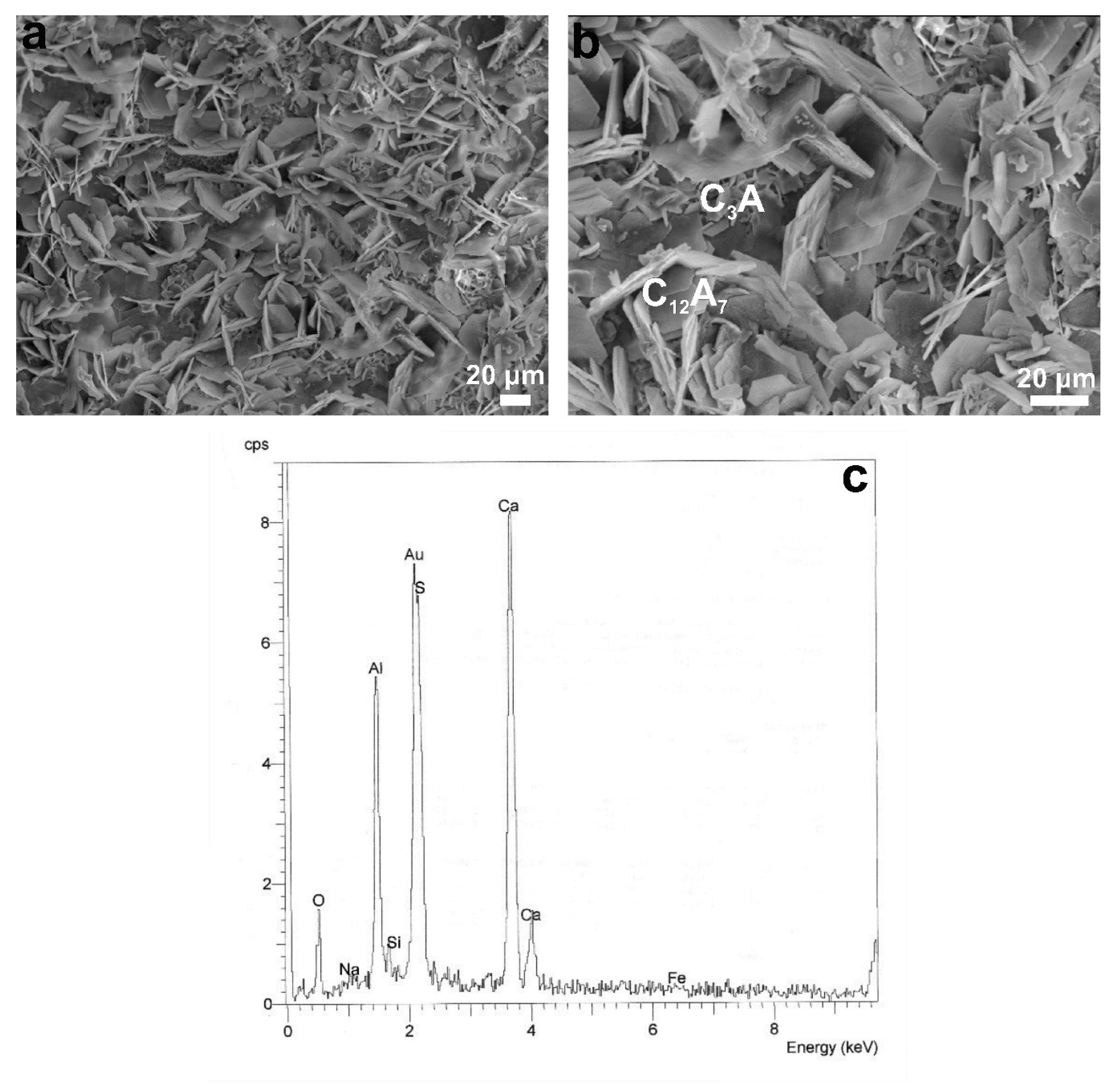
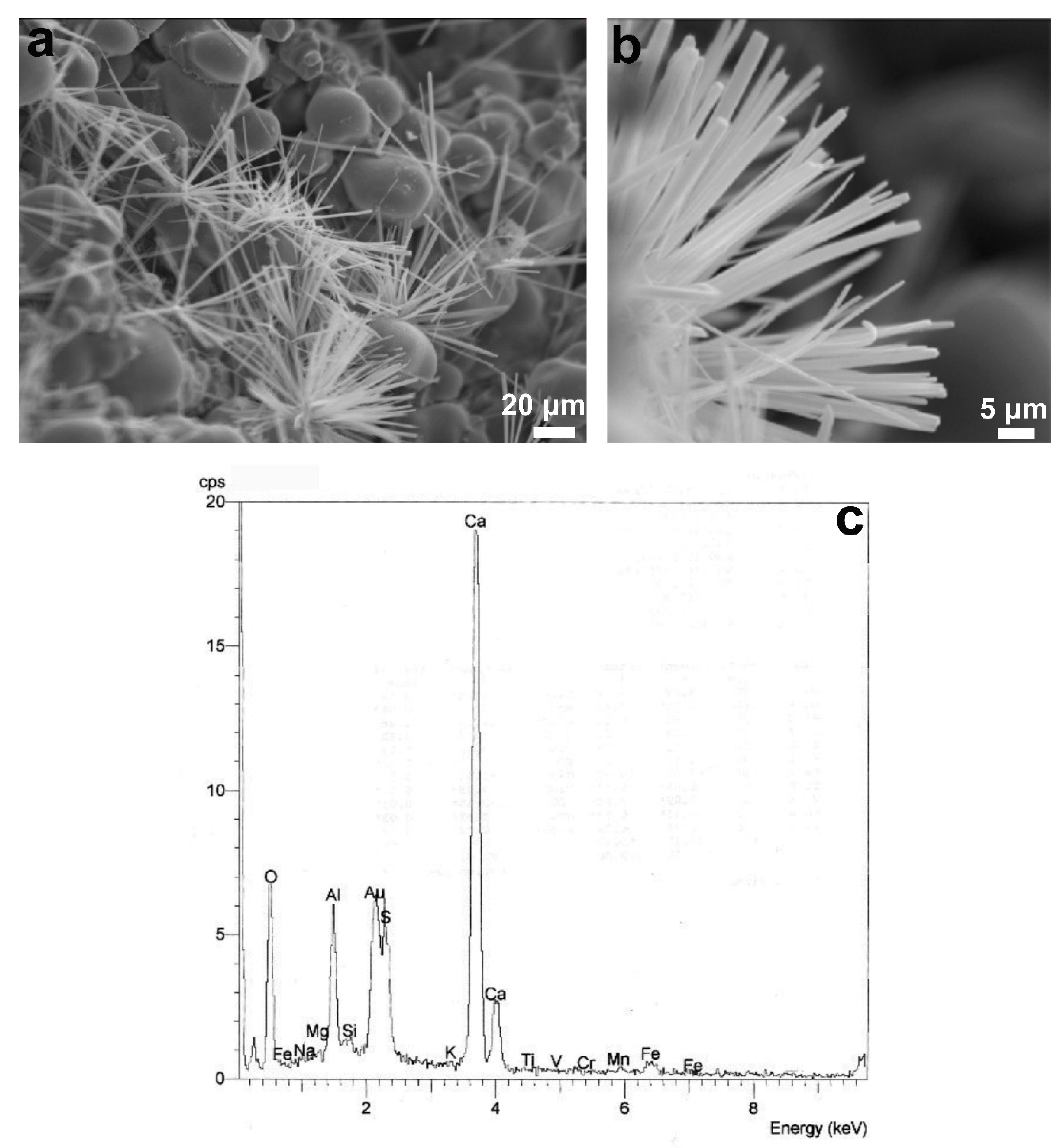
3.1.2. Mineralogical Characterization and Microstructure

The mineralogical analyses of the slags are summarized in Table 3 and Table 4 for the air and water cooled samples, respectively. The high number of phases detected in each XRD pattern (Figure 1), therefore high overlapping of peaks, made their distinguishing quite difficult and SEM/EDS analysis assisted substantially towards this direction (Table 5). Special care was taken to present selected microanalyses that are either stoichiometric or closely approximate the stoichiometry, since the fractured analyzed surfaces of samples prevented accurate quantitative analyses. Moreover, characteristic microphotographs of their structure obtained by optical microscopy and SEM are presented in Figure 2, Figure 3, Figure 4 and Figure 5.
According to the obtained results, well-formed crystals were also detected in the slags cooled in water as shown in Figure 1. The constrained amorphous (glass) content was also verified by the optical observation under polarized light of the water-cooled 35–45 μm slags fraction as indicatively shown in Figure 2a. In order to obtain vitreous granulated slag, as in GGBS, high pressure water jets are required [19]. The main differences in the mineralogical phases identified between air and water-cooled slags of the same chemical composition were the polymorphs of dicalcium silicate attributed to the different rates of cooling. The environmental conditions during the smelting trials and thus slags tapping (temperature <0 °C, rainfall) and formation of microcrystalline material prevented the formation of γ-C2S (γ-2CaO·SiO2) and the disintegration of the cooled slag phase due to β→γ-C2S transformation even in the air-cooled slags. The later takes place in cases of slow cooling rate and its presence is not desired in cementitious materials, since it exhibits slight hydraulic properties not contributing to strength development. The co-existence of α and/or α′ and β-C2S phases in the slag samples indicates that the theoretical thermodynamic transformation was not completed due to rapid temperature drop mainly in the initial phase of the cooling process [30]. The incorporation of Μg in C2S could lead to the formation of bredigite, Ca14Mg2(SiO4)8—once the solubility limits in α and α′-C2S are exceeded. Usually, its composition varies between Ca1.75Mg0.25 and Ca1.7Mg0.3 at ~1300 °C per SiO4 [31] and its presence has been reported in cases of EAF steelmaking slags [32]. However, α′-C2S and bredigite have different structures, it has been confirmed [31,33] that the similarity in their XRD patterns makes distinguishing them very difficult (Figure 1). In this work, the nomenclature of α′-C2S has been currently attributed to a probable combination of both phases. The semiquantitative analysis obtained by SEM-EDS verified solubility of Mg in C2S, as well as the existence of purer C2S micro-areas, while Al, Mn and Fe incorporated in the crystal lattice was also identified (Table 5, Figure 2). The incorporation of foreign ions in the structure of dicalcium silicates, as well as deviation from the stoichiometric composition, favor the stabilization of the α′ and β phases [34].
In all examined samples, magnesiowüstite phase was identified (Table 5, Figure 3a). Magnesiowüstite comprises a solid solution between MgO and FeO and it is commonly found in the mineralogical composition of steelmaking slags [19,21,35,36]. It is reflected in the XRD patterns by displaced peaks located between pure wüstite (41.890 2θ strongest line) and periclase ones (42.917 2θ strongest line), depending on the Mg/Fe2+ ratio and it has been assigned as Mg1−xFexO (MW). Investigations have shown that the composition of these types of solid solutions in the slag depends on slag chemistry and on the cooling rate. Slower cooling rate will promote the enrichment of FeO into the structure, while MgO predominates by increasing the cooling rate [21,36]. This may explain the difference observed when comparing the microanalysis of MW phase in slags, 3-1a versus 3-1b (Table 5). Nevertheless, it may be noticed that the strongly reduced %FeO in the chemical analysis of 4-2 slag led to rich Mg-MW even in the air-cooled slag sample.
Incorporation of Manganese, Calcium and Chromium (most possibly divalent) in magnesiowüstite solid solutions was also detected in the course of SEM-EDS analysis in the slag samples. Chromium was also identified in XRD analysis in chromite phase in two of the air-cooled slag samples (3-1,2a). Increase of cooling rate prevents the thermodynamic chromite spinel formation from the MW solid solution with temperature drop, preserving Chromium in the MW phase. In high basicity EAF slags, primary crystallization of Chromium occurs in magnesiowüstite [21,36]. This is illustrated in the microanalyses of the mageniowüstite solid solution phases in the higher basicity air-cooled slag samples 4 and 5, (Table 5). Increase of FeO amount in these solid solutions has also been reported to decrease its leachability from the slag, which is an advantageous property for its further envisaged use [21,36].
Overall, iron in the examined slags was mainly in the divalent state bound in the MW phase as described above. In slag 5, where limited reduction of iron oxides was targeted through the applied experimental conditions, brownmillerite, Ca4Al2Fe2O10 (C4AF) and calcium ferrite (CaO.2Fe2O3) were additionally identified, also indicating presence of trivalent iron in the slag. Brownmillerite is commonly met in the clinker of Portland cement, while calcium ferrite phase in contrast to MW has been reported as phase of hydraulic nature, too [18]. Micro-areas rich in C4AF crystals were detected by SEM/EDS examinations in slag 5 sample (Table 5, Figure 3b).
Tricalcium silicate 3CaO.SiO2 (C3S), being the most important phase in cement for early strength development among the calcium silicates, was mainly detected in the slag products, 4-2a, b and 5, where the basicity was higher, while some traces were also found in slag 3-1b. Typical micrograph and microanalyses of identified C3S hexagonal crystal in the slags microstructure is shown in Figure 3c and Table 5, respectively. Presence of merwinite, 3CaO·MgO·2SiO2 (C3MS2), common constituent of EAF steelmaking slags was also identified in the XRD and SEM/EDS analysis of the slags. Characteristic micro-area of solidified merwinite crystals is shown in Figure 3d and representative C3MS2 microanalyses are provided in Table 5. According to [15] low grain size merwinite in EAFs contributes to slags cementitious properties exhibiting a hydration behavior similar to that of di- and tri-calcium silicates.
Calcium aluminate phases, such as 3CaO·Al2O3 (C3A) and 12CaO·7Al2O3 (C12A7), which also contribute to strength development upon hydration, participated in the mineralogical composition of the slags, being more abundant in slags 4-2(Table 5, Figure 4), which had the highest content of Al2O3. In addition, gehlenite C2AS (2CaOAl2O3SiO2) was also often detected (Figure 1, Table 5). The retention of some of the water-cooled slags in water during their cooling resulted in the fast hydration of part of the calcium aluminate phases. The presence of sulfur in these slags led to the formation of monosulfate, C4ASH12 (4CaO·Al2O3·SO3·12H2O), found as thin hexagonal plates, (Figure 4c) or ettringiteC6AS3H32 (6CaO·Al2O3·3SO3·32H2O) detected in the form of needles (Figure 5). These hydrated phases were only detected locally in SEM backscattered images. It has also been reported that in most cases it is not possible to detect ettringite by XRD [37]. These phases are usually encountered during the hydration of Portland cements due to the reaction of gypsum with calcium aluminates according to the following reactions:
C3A + 3CSH2 + 26H = C6AS3H32 (ettringite formation)
2C3A + C6AS3H32 + 4H = 3C4ASH12 (monosulfate)
During cement hydration process, if added gypsum is consumed before the complete hydration of C3A, the remaining C3A reacts with ettringite producing monosulfate. The higher calcium aluminate content, due to higher Al2O3 percentage in the case of slag 4-2b has possibly allowed monosulfate formation by a similar mechanism.

3.2. Properties of Composite Portland Cements (CPCs) Manufactured by 20% Slag

The current European Norm [17] for common cements refers only to the utilization of ground granulated blast furnace slag (GGBS) in cement production. Thus, the physical and mechanical characteristics of all the composite cement products, manufactured using the air-cooled and water-cooled slags in the present study, are compared to the requirements for composite Portland cements (CPCs) with blast furnace slags, (CEM II). The target of this study is to evaluate the feasibility of the produced slags utilization in common cement production and further the correlation of the obtained results to the microstructural characteristics of the used slags. The main difference is that blast furnace slag accepted in cement production according to EN 197-1 [17], contains at least two-thirds by mass of glassy slag and has minimum iron oxide content.

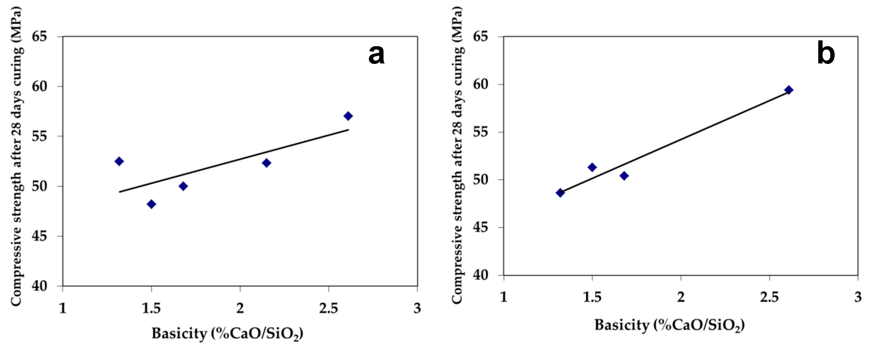
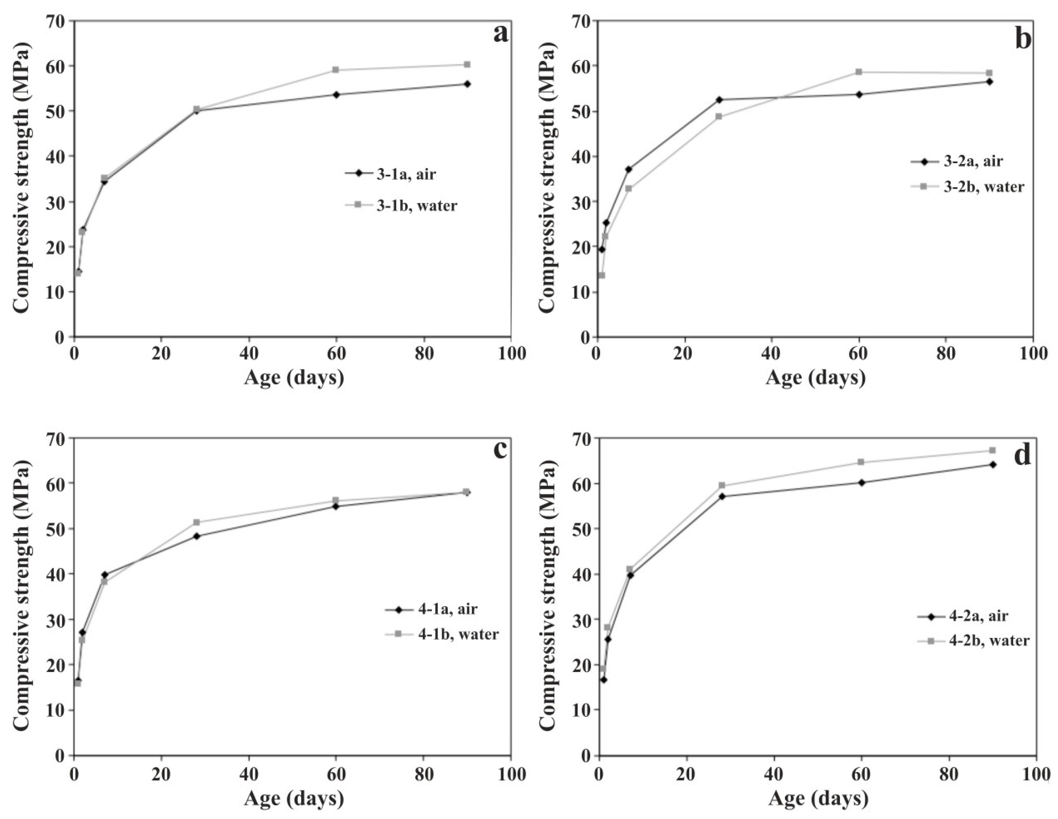
3.2.1. Compressive Strength

The early, late and long term compressive strengths development of the CPCs with 20wt.% slag are presented in Table 6 and Figure 6a,b for the air and water-cooled slags, respectively. In addition, the results are compared to the OPC (95% clinker and 5% gypsum). All investigated mixtures were found to be within the values of EN 197-1 [17]. The early strengths (2 days of curing) were found higher than 2 Pa and 28-day curing strengths were in the range of 48.2–59.4 MPa. The preservation of relatively high early strengths observed in all the composite cements despite their limited and/or no C3S content is most possibly attributed to the contained calcium aluminates.
Concerning the effect of iron oxide content, in general, for high FeOx containing slags, the reduction of the % FeOx is expected to enhance its cementitious properties, as this increases mainly the mass of residual calcium and silicon oxides, the combination of which leads to the formation of desired hydraulic phases. According to the results of this study, the %FeOx of the slags, within the studied concentration limits, 3.85 wt.%–21.1 wt.%, did not present significant influence on the compressive strengths of the produced cements. The highest values were obtained using slag 4-2, with 3.85% FeOx content both for the air (a) and water-cooled slag-product (b). In fact, the CPC prepared by 4-2b slag acquired slightly higher compressive strengths than those of the blank OPC. This can be attributed not only to the lower FeOx content, but also to most the hydraulic phases formed in these slags as presented above. These slags were abundant in calcium silicates (C2S, C3S) and calcium aluminates (C3A, C12A7). The strengths of the rest of the composite cements lay at similar levels, despite the difference in their FeOx content. Even the cement prepared with the slag having the highest FeOx content (~21%), presented considerable compressive strength values. This can be correlated not only with the calcium silicate compounds (C3S, C2S) detected in this slag, but also with the fact that part of the iron was in trivalent state resulting in the formation of brownmillerite, C4AF, which exhibits good and intermediate contribution in the early in the final cement compressive strengths, respectively. This observation demonstrates that the state of Fe in the slag influences the morphology and its latent hydraulic properties in agreement with the findings of [18]. It is also noticed that the main peaks of the XRD pattern of this slag were attributed to magnesiowüstite. However, its negative effect on strengths development was counterbalanced by the presence of the other active phases in the slag mass. These results manifest that the strength development of the manufactured composite cement is highly affected by the mineralogical composition of the used slag. According to these results, in case of slags with crystalline structure, the most important feature for positive contribution to the compressive strength of the cement is the formation of mineralogical phases similar to those met in clinker.
The beneficial effect of slag basicity on the 28-days of curing achieved compressive strengths of the CPCs for the air and water-cooled slags is presented in Figure 7. In general, the higher the slag basicity in the range of 0.9–2.7, the higher are the latent hydraulic properties of the slag expected to be, since slag’s basicity is directly related to the formation of the hydraulic calcium silicate phases [19,38,39]. Deviation from absolute linearity in the obtained results is related to the fact that strength development does not solely depend on calcium silicates, thus on the CaO/SiO2 ratio, but also on the other slag’s constituents, which are not at the same levels in the slags. In example, the concentration of alumina, which participates in the formation of cementitious phases, also has an effect.
As illustrated in Figure 8, the means of cooling, given the way it was employed, did not result in significant differences upon the obtained strength results. The slightly higher long term values in case of water-cooled slags may be possibly correlated to some amorphous content, as well as the presence of more active C2S polymorphs [40]. Probably, cooling with high pressure water jets and formation of vitreous slags of these compositions could favor even higher strengths.

3.2.2. Setting Time

The initial and final setting times of the manufactured CPS are presented in Table 7. For all the examined slags, the initial setting time was higher than the minimum one specified in EN 197-1 [17] for all cement types. Indicatively, according to the standard [17], 75 min is the highest initial setting time required for the 32.5 N/R cements, while the required time is reduced for higher strength cement types, i.e., for 52.5 N/R cements the corresponding minimum requirement is 45 min. Setting and consequently hardening of the water–cement mixture is the result of complex physicochemical changes, among which hydration reactions play a key role. Overall, cement setting is directly linked with its concentration in calcium aluminates and the percentage of added calcium sulfate. The high setting rate of pure cement comes from C3A, which reacts instantly with water. Calcium sulfate addition aims at the modification of C3A hydration reaction through the formation of an intermediate salt, which has the ability to significantly increase initial setting time. Depending on the concentration of aluminum and sulfate ions in solution, the crystalline precipitate can be either ettringite in the form of needle shape crystals or monosulfate with hexagonal crystal structure. Ettringite crystals, being the first to form, contribute in gradual setting of cement paste and finally in initial strength development. Different setting processes take place depending on the reactivity of calcium aluminates and their mass ratio to available sulfate ions [28]. Due to the increased rates of the aforementioned phenomena in case cement is exposed to humidity during its storage period, its subsequent setting behavior changes. Absorption of humidity results in reduction of C3A reactivity and setting retardation. Furthermore, cement exposure to humidity in any case results in reduced compressive strengths. In some of the water-cooled slags of the present study, formation of such salts was detected in their mineralogical composition as presented above, possibly as a result of their contents in calcium aluminate phases and sulfur, their residence time in water during cooling and relative humidity during collection and storage. According to the results of Table 7, all the prepared cement specimens present relatively comparable setting times to OPC. Overall, the highest initial setting time was measured in the cement containing 3-1b slag, in which ettringite was identified resulting in setting retardation. For the cements manufactured with air-cooled slags, cement with slag 3-1a also presented the highest setting time. These results indicate that most possibly C3A content was relatively low in 3-1 slags, which may partially explain why the hydration reaction in 3-1b stopped to ettringite and did not proceed to monosulfate formation. For the rest of the cements, the shortest times were measured in those specimens, where slags abundant in calcium aluminate phases was used. Moreover, C12A7 and C4AF phases exhibit similar behavior to C3A, concerning fast hydration rate and reaction to sulfates. This is why the shortest setting time was measured in the cement manufactured by slag 5, containing all three crystalline phases. Furthermore, in all cases the cements prepared with the water-cooled slags exhibited a delay in setting initiation compared to the cements, where the corresponding air-cooled slags was used. This can be attributed to the reduction of calcium aluminates reactivity due to humidity. The slowest time was recorded for 4-2b slag, where hexagonal monosulfate crystals was detected, indicating excess of contained calcium aluminates. In any case, cement setting time can be adjusted by the proper calcium sulfate addition depending on the technological requirements of the cement provided that the chemical specification regarding SO3 concentration, 3.5% for CEM II Portland cements is also met. This value corresponds to 1.4% S. Sulfur range 0.2 wt.%–0.39 wt.% in the studied slag lays well below this limit value.

3.2.3. Soundness (Expansion)

All manufactured CPCs exhibited good behavior in terms of volume stability as shown in the expansion values determined by Le Chatelier soundness test (Table 8), which are well over than the upper limit of 10 mm, indicating that free CaO and MgO, the crystalline phases well known to cause expansion issues during the hydration of cement, if present, are in very low concentrations. It is noted that no traces of free lime were detected either in the XRD analysis or in the SEM-EDS examination of the slag samples. Furthermore, in all cases pure periclase was not identified. Instead formation of MW solid solutions with different FeO/MgO ratios was always spotted, accompanied by incorporation of mainly Mn and less Ca. These formations seem to inhibit transformation to hydrated compounds causing the expansion. According to Qian et al. [35], the higher the FeO/MgO ratio of such solutions, the lower the potential of brucite transformation reaction, which is accountable for the expansion in case of pure periclase.

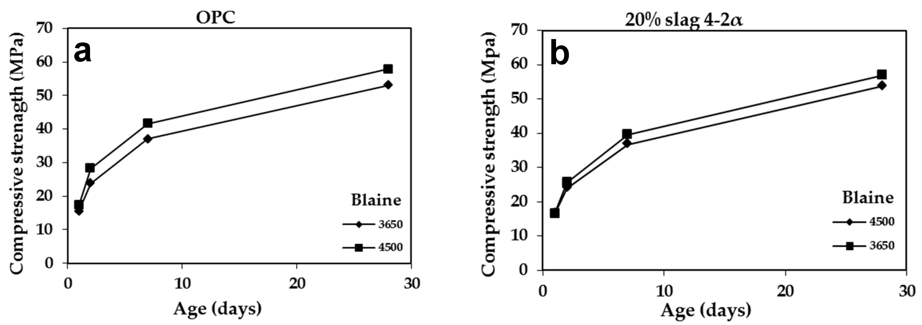
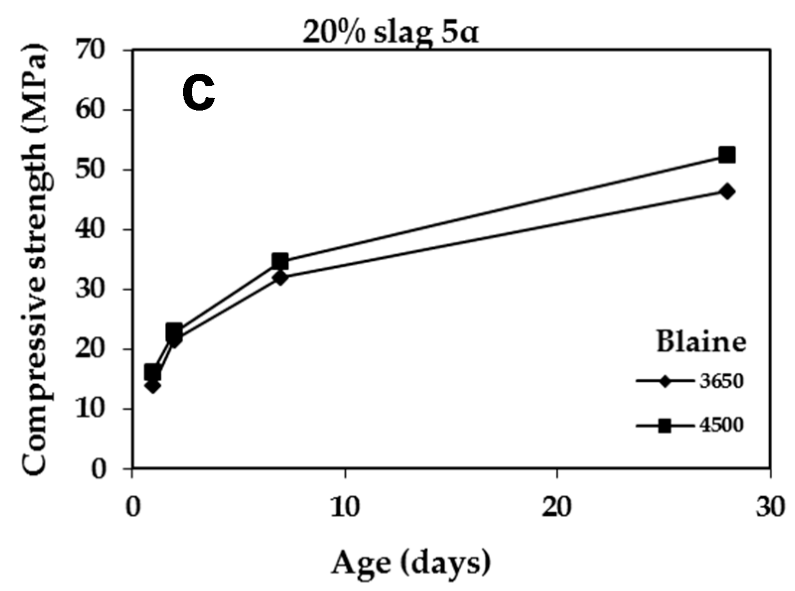
3.2.4. Effect of Blaine

The higher grinding times that were required in case of CPCs manufacturing compared to OPC for Blaine 4500 cm2/g, Table 6, indicate higher energy requirements. In view of economic and environmental considerations, grinding targeting to lower Blaine level was indicatively examined. For this purpose, two CPCs with 20% slag were selectively prepared at 3650 cm2/g blaine using slags 4-2a and 5 having the lowest and highest iron oxide content, respectively. According to the obtained results (Table 9, Figure 9), although the compressive strengths of the produced cements are lower than the corresponding ones at 4500 cm2/g, as expected, they still fall inside the EN-197-1 [17] cement specifications. In fact, cement with 4-2a slag conforms to the limits of the high strength cement category 52.5 N even at the lower Blaine. These results point out that even at lower Blaine the produced slags could be used up to 20% in cement mass replacing clinker. The reduced grinding time employed in case of the lower compared to the higher Blaine, corresponds to reduced manufacturing energy requirements. In case of commercial use, cement Blaine and thus grinding time depends on the requirements of the construction application for which it is intended, namely the strength specs. Nevertheless, we should not forget that despite the additional grinding time required for the preparation of composite cements, the economic benefit to the cement producer is still significant, due to the substitution of 21% of the mass of clinker by slag, which is an energy upgraded material and does not need to go through the high energy demanding firing stage in the rotary kiln during the production of cement.

3.3. Properties of Slag Cements (SCs) manufactured by 40% Slag

The physical and mechanical characteristics of all the slag cement products, manufactured using the air-cooled and water-cooled slags in the present study, are evaluated comparatively to the requirements of EN 197-1 [17] for slag cements with blast furnace slags, (CEM III). Slag cement with 4-1a slag was not manufactured because the available slag mass was not sufficient. Further, in slag cement made with slag 4-1b different clinker batch was used due to inadequate clinker mass. New reference OPC was also prepared by the new clinker for comparison reasons noted by (*) in the corresponding results tables thereafter.

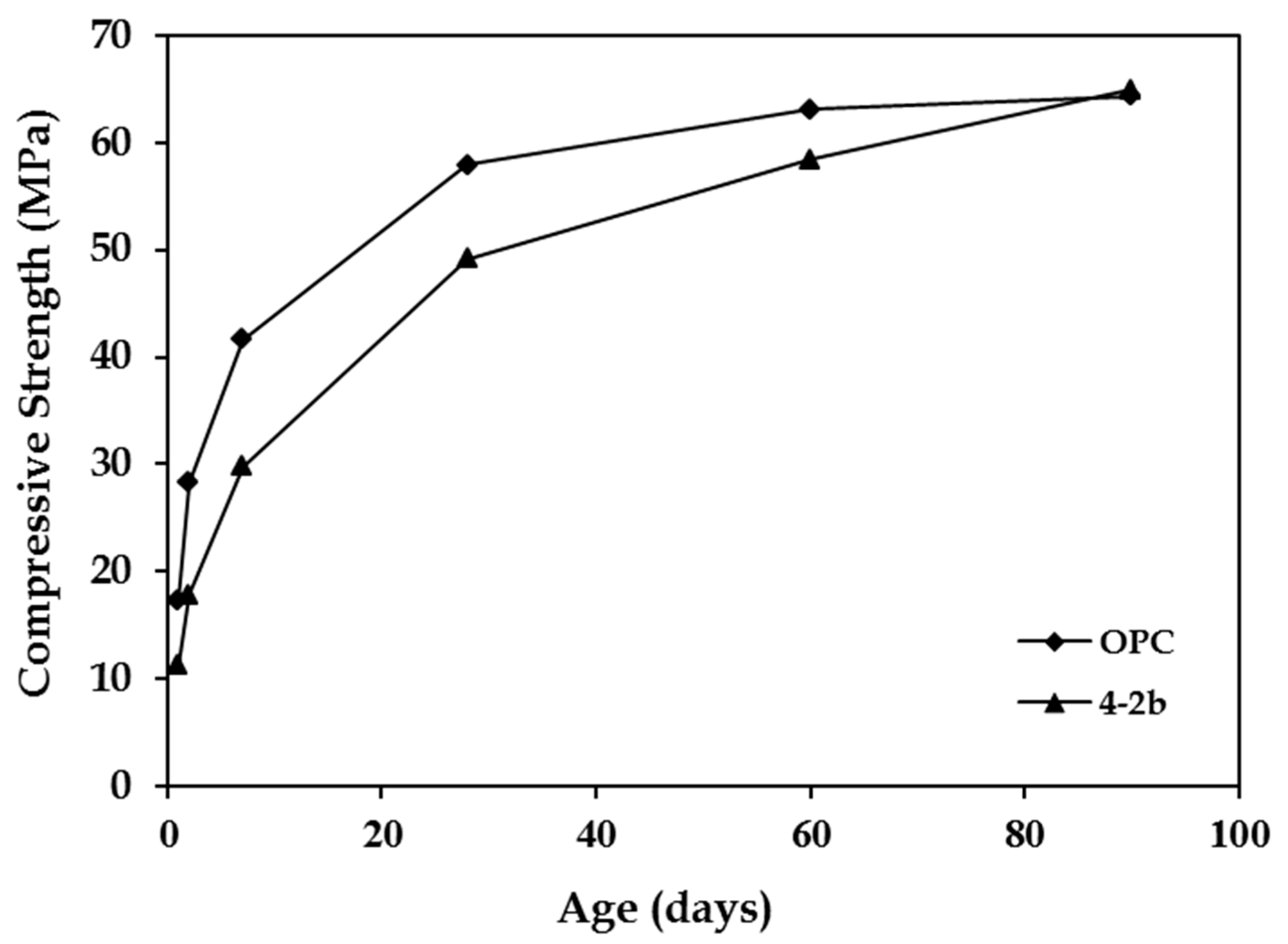
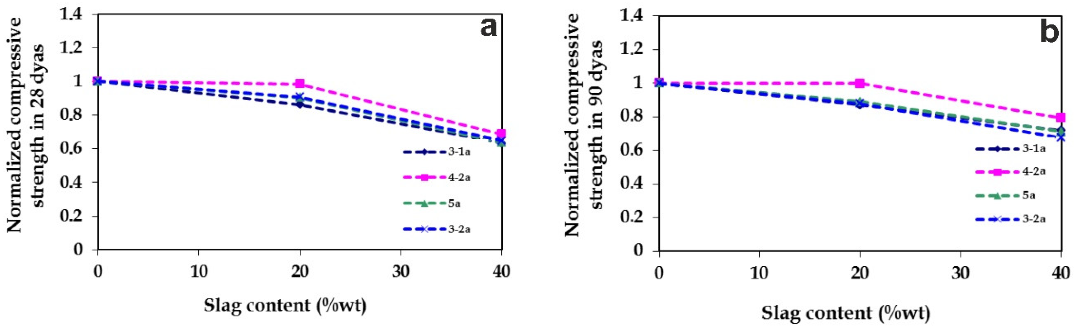
3.3.1. Compressive Strength

The early, late and long term compressive strengths of the slag cements (SCs) with 40wt.% slag are presented in Table 10. The obtained compressive strengths of all the slag-cements ranging between 35.4 and 49.2 MPa are within the limits of EN 197-1 [17]. The results indicate that the compressive strengths of the slag cements are not solely affected by the FeO content of used slags in agreement with the findings of CPCs. The highest strengths for SCs with 40% slag, for both air-cooled and water-cooled slags, are obtained for the case of slag 4-2 in agreement with the results of the CPCs with 20% slag. In fact, as it is illustrated in Figure 10, the slag cement manufactured with 4-2b slag exhibits such a considerable increase in the long term compressive strength development that after 90 days, the values attained by OPC are reached.
In Figure 11 and Figure 12 the normalized late (28 days) and long term (90 days) compressive strengths of the prepared cements in relation to their slag content are presented for the mixtures produced with the air and water-cooled slags, respectively. As normalized strength the following strength ratio was defined: Compressive strength obtained by the mixture where slag was used/ Compressive strength obtained by the corresponding OPC. Overall, it can be observed that the increase in the slag content results in the decrease of the strength. Nevertheless, the contained C2S of the slags results in a smoother decrease in case of long term strengths.

3.3.2. Setting Time

The initial and final setting times of the manufactured slag cements is presented in Table 11. Initial setting times of cements with 40% slag are lower than the corresponding ones with 20% and in some cases lay marginally within the limits of EN 197-1 [17] for 32.5 typical strength cements. The higher initial setting time was measured for the mixture with slag 3-1a, in agreement to the results obtained in case of CPCs with 20% slag. Overall, the relatively fast onset setting of the slag cement mixtures is mainly correlated to their calcium aluminates content of the used slags as described above. However, the obtained results cannot totally be/gr explained by the mineralogical composition of the slags. For example, for the water-cooled slags 4-1b and 3-2b, although the use of 20% in cement resulted in increase of the initial setting time compared to OPC, increasing slag content to 40%, resulted in decreased initial setting time. Further, unexpected fast onset of setting was also measured for cement with slag 3-1b, in which the ettringite was detected. These results are most probably attributed to the “false set” phenomenon, which is usually experienced in the case of partially hydrated cements deriving from improper storage conditions. It is noted that the used clinker was stored for a period of almost one and a half year in plant’s warehouse for the elaboration of all the lab scale experiments.

3.3.3. Soundness (Expansion)

The expansion values measured for the slag cements are presented Table 12. However, these values are higher than those of cements with 20% slag, they still remain well below the standard limit value of 10 mm. These encouraging results support that 40% slag content in the cement substituting clinker can take place without causing volume stability issues.

3.3.4. Grinding Time

Concerning the grinding time of the slag cements, it was generally observed to be higher than that one required for the OPC and the corresponding CPCs. Exceptions are the mixtures of slag 3-2a and 4-2a, for which reduction in grinding time was observed in case of 40% slag content. It is noticeable that these slags exhibited the highest grinding time among the cements with 20% slag. In addition, for 4-2b slag, which presented a relatively high grinding time in case of 20%, in the case of 40% the difference is only two min. The combination of these results indicates that when the content of slag of relatively high hardness increases in the mixture, a “self-grinding” phenomenon takes place, where the slag itself contributes to its grinding, thereby reducing the time required in order for the corresponding cement mixture to achieve the same Blaine. This observation is particularly important in terms of energy consumption.

3.4. Suppressing CO2 Emissions by Use of Slag in Cement Manufacturing

International policy frameworks developed by the Paris Agreement Sustainable Development Goals (SDG) calls for immediate actions to be taken to suppress CO2 emissions. According to the World cement Association, cement producers have developed plans to contribute towards this direction, by outlining pathways for low-carbon cement production. Despite the profound benefits that cement offers in shaping our modern built environment, it is undoubtedly a massive source of carbon dioxide to the atmosphere. According to estimates from the International Energy Agency, it accounts for about 7 percent of all global carbon emissions, meaning that it is the second-largest single industrial emitter, second only to the iron and steel industry. Further to this, it is expected that cement production will vastly increase by within the next 20 years due to the increasing demand in cement from developing countries. Thus, solutions must be implemented to reduce CO2 emissions because this it may likely put the Paris Agreement’s global climate targets in jeopardy (e.g., [41,42]). The production of Portland cement leaves a notable carbon footprint due to the use of fossil fuels to create the necessary intense heating but more important, from the chemical decomposition of limestone that releases large amounts of CO2 as a byproduct. Proposed solutions include the use of alternative fuels, the implementation of innovative carbon capture technologies, as well as the use of recycled byproducts from other industries, such as slag, fly ash and clay material.
Scientists and cement industries are combining forces and are expected to succeed in gradually reducing CO2 emissions, although there are still many barriers to be dealt with [43]. Blast furnace slag production can partially replace clinker in cement by even up to 50% or directly in to be used in concrete. Moving one step forward, the results of the present research demonstrate that the allowable main cement constituents list of the current cement norm [17] could potentially be expanded to include other kind of slags beyond the blast furnace slags. The testing principles applied in this study demonstrate that the selection criteria should not rule out slags just based on the chemical analysis and amorphous slag content as currently in place for the GGBFS, but consider whether the properties of the corresponding obtained cements meet the required technical specifications for their application. Increasing the potential volume of slag cement would result in significant environmental and economic benefits, since its production requires less than a fifth of the energy compared to the production of Portland cement and releases less than a fifteenth of the carbon dioxide emissions. Additional sustainable benefits are that manufacture of slag cement does not require the quarrying of virgin limestone materials, but also the fact that the slag is considered as a key link to achieve a sustainable circular economy, to move our society from a linear economic system by using slag as an eco-friendly byproduct.

4. Conclusions

The examined slags produced in the course of the industrially tested Ni-dust and laterite ore fines recycling smelting process could be used in the cement industry for the manufacturing of special type composite Portland or slag cements up to 40% by mass with significant environmental and economic benefits, since the physical and mechanical characteristics of all examined cement products were found to meet the requirements of the regulation set for cements. For the 4-2a, b slags, exhibiting the highest strength results, even higher addition could be most possibly feasible. The present research revealed that the most critical parameter in the compressive strength development of the slag cements is the mineralogical composition of the slag. Increasing slag basicity enhances formation of desired hydraulic calcium silicates, as well as calcium aluminates in presence of adequate alumina. Formation of magnesiowüstite solid solutions and iron valence also affect the obtained physical and mechanical properties of the corresponding slag cements, respectively, suppressing potential expansion issues. Rapid cooling enhances slag’s cementitious properties. However, the results showed that even in cases where rapid cooling to obtain glassy matrix is not feasible, adjustment of slag analysis to obtain mineralogical phases similar to those met in clinker of OPC, even at higher FeO contents (up to 21wt.%), can result in production of slag with considerable latent hydraulic properties. These findings indicate that there is also potentially space for improvement in conventional EAF steel slags chemical composition to allow for their wider use in building sector. Overall, this research demonstrated that the recycling of metallurgical wastes, through the reduction smelting route in DC–EAF, provides perspectives for development of zero residues metallurgical recycling processes, since besides the recovery of valuable metals in the liquid bath, produced slag analysis can be adjusted, on one hand in favor of the metallurgical yield of the process and on the other to allow its further utilization in the manufacturing of high added value environmental friendly building materials accountable for less CO2 footprint; relative to the amount of clinker being substituted.

Supplementary Materials

The following are available online at https://www.mdpi.com/2076-3417/10/13/4670/s1, Figure S1: Flow sheet of the zero residues production smelting process for metallurgical dusts and ore fines recycling [4].

Author Contributions

T.T. coordinated the research, designed and carried out the testing, the interpretation of the results and the writing of the manuscript; P.L. participated in the interpretation of the results and contributed to the manuscript writing; P.P.G. participated in the interpretation of the results and contributed to the manuscript writing; A.R. participated in the interpretation of the results and contributed to the manuscript writing; P.K. participated to the manuscript writing; N.K. participated to the manuscript writing; P.P. participated in the interpretation of the results and contributed to the manuscript writing. All authors have read and agreed to the published version of the manuscript.

Funding

The industrial Ni-dust and laterite ore fines smelting trials, in the course of which, the slags were produced were jointly funded by the government of Niedersachsen and Georgsmarienhütte Gmbh steelmaking company.

Acknowledgments

The present announcement is dedicated to the memory of Ing. D.C. Papamantellos for his overall guidance and contribution. The industrial Ni-dust smelting trials and slags production took place in the DC–EAF of Georsgmarienhütte Gmbh steel making company. LARCO GMMS.A. provided the Ni-dust and laterite ore-fines. Manufacturing and testing of the slag cements was performed in the R&D center of TITAN S.A. Finally, special thanks are due to Editor and four anonymous reviewers for their precious comments on improving the manuscript.

Conflicts of Interest

The authors declare no conflicts of interest.

References

  1. Yunos, N.F.M.; Zaharia, M.; Ismail, A.N.; Idris, M.A. Transforming Waste Materials as Resources for EAF Steel making. Int. J. Mater. Eng. 2014, 4, 167–170. [Google Scholar]
  2. Jones, R.T.; Hayman, D.A.; Denton, G.M. Recovery of cobalt, nickel and copper from slags using DC-arc furnace technology, International Symposium on Challenges of Process Intensification. In Proceedings of the 35th Annual Conference of Metallurgists, Montreal, QC, Canada, 24–29 August 1996. [Google Scholar]
  3. Burström, G.Y.; Kuhn, M.; Piret, J. Reduction of Steelmaking Slags for Recovery of Valuable Metals and Oxide Materials. In Proceedings of the 6th International Conference on Molten Slags, Fluxes and Salts, Stockholm, Sweden-Helsinki, Finland, 12–17 June 2000. [Google Scholar]
  4. Tzevelekou, T.V.; Geck, H.G.; Hüllen, P.; Höfer, F.; Papamantellos, D.C. Direct Smelting of Metallurgical Dusts and Ore Fines in a 125t DC-HEP Furnace. Steel Res. Int. 2004, 75, 382–392. [Google Scholar] [CrossRef]
  5. Memoli, F.; Mapelli, C.; Guzzon, M. Recycling of Ladle Slag in the EAF: A Way to Improve Environmental Conditions and Reduce Variable Costs in Steel Plants. Iron Steel Technol. 2007, 4, 68–76. [Google Scholar]
  6. Heo, J.H.; Kim, T.S.; Sahajwalla, V.; Park, J.H. Observations of FeO Reduction in Electric Arc Furnace Slag by Aluminum Black Dross: Effect of CaO Fluxing on Slag Morphology. Metal Mater. Trans. B 2020, 51, 1201–1210. [Google Scholar] [CrossRef]
  7. Schliephake, H.; Algermissen, D. How far away is the steel industry from the target now waste? Proceedings EUROSLAG. In Proceedings of the 10th European Slag Conference Slag based products–best practices for Circular Economy, Thessaloniki, Greece, 8–11 October 2019. [Google Scholar]
  8. Alexopoulou, I.E.; Angelopoulos, G.N.; Papamantellos, D.C.; Rentizelas, G. The dust recycling problem of the FeNi production at Larymna/Greece—Part II: New perspectives and proposals. Erzmetall 1994, 47, 651–657. [Google Scholar]
  9. Kotze, J. Pilot plant production of ferronickel from nickel oxide ores and dusts in a DC arc furnace. Miner. Eng. 2002, 15, 1017–1022. [Google Scholar] [CrossRef]
  10. Osmanović, Z.; Haračić, N.; Zelić, J.; Lihić, A. Slag Cement Production in Terms of Emission Reducing; ISEM: Adiyaman, Turkey, 2014. [Google Scholar]
  11. Schorcht, F.; Kourti, I.; Scalet, B.M.; Roudier, S.; Delgado Sancho, L. Best Available Techniques (BAT) Reference Document for the Production of Cement, Lime and Magnesium Oxide: Industrial Emissions Directive 2010/75/EU: (Integrated Pollution Prevention and Control); Luxembourg Publications Office of the European Union: Brussels, Belgium, 2013. [Google Scholar]
  12. Pellegrino, C.; Faleschini, F.; Meyer, C. Developments in the Formulation and Reinforcement of Concrete, 2nd ed.; Woodhead Publishing Series in Civil and Structural Engineering: Vancouver, BC, Canada, 2019. [Google Scholar]
  13. Kim, H.S.; Kim, K.S.; Jung, S.S.; Hwang, J.I.; Choi, J.S.; Sohn, I. Valorization of electric arc furnace primary steelmaking slags for cement applications. Waste Manag. 2015, 41, 85–93. [Google Scholar] [CrossRef] [PubMed]
  14. Zhang, L.; Drelich, J.W.; Neelameggham, N.R.; Guillen, D.P.; Haque, N.; Zhu, J.; Sun, Z.; Wang, T.; Howarter, J.A.; Tesfaye, F.; et al. (Eds.) Energy Technol 2017—Carbon Dioxide Management and Other Technologies, The Minerals, Metals & Materials Series, 1, XII, 499; Springer: Berlin, Germany, 2017. [Google Scholar] [CrossRef]
  15. Luckman, M.; Vitta, S.; Venkateswaran, D. Cementitious and pozzolanic behavior of electric arc furnace steel slags. Cem. Concr Res. 2009, 39, 102–109. [Google Scholar]
  16. Branca, T.A.; Colla, V.; Algermissen, D.; Granbom, H.; Martini, U.; Morillon, A.; Pietruck, R.; Rosendahl, S. Reuse and Recycling of By-Products in the Steel Sector: Recent Achievements Paving the Way to Circular Economy and Industrial Symbiosis in Europe. Metals 2020, 10, 345. [Google Scholar] [CrossRef] [Green Version]
  17. British Standard EN 197 Part 1. Cement-Composition, Specifications and Conformity Criteria for Common Cements; BSI: London, UK, 2011. [Google Scholar]
  18. Murphy, N.; Meadwcroft, T.R.; Barr, P.V. Enhancement of the cementitious properties of steelmaking slag. Can. Metal. Q. 1997, 36, 315–331. [Google Scholar] [CrossRef]
  19. Shi, C.; Qian, J. High performance cementing materials from industrial slags–a review. Resour. Conserv. Recycl. 2000, 29, 195–207. [Google Scholar] [CrossRef]
  20. Rojas, M.F.; de Rojas, M.I.S. Chemical assessment of the electric arc furnace slag as construction material: Expansive formations. Cem. Concr. Res. 2004, 34, 1881–1888. [Google Scholar] [CrossRef]
  21. Engstrom, F.; Pontikes, Y.; Geysen, D.; Jones, P.T.; Bjorkman, B.; Blanpain, B. Review: Hot stage engineering to improve slag valorisation options. In Proceedings of the 2nd International Slag Valorization Symposium, The transition of sustainable materials management, Leuven, Belgium, 18–20 April 2011. [Google Scholar]
  22. Pontikes, Y.; Malfliet, A. Slag Valorisation as a Contribution to Zero-Waste Metallurgy. J. Sustain. Metall. 2016, 2, 1–2. [Google Scholar] [CrossRef] [Green Version]
  23. Li, Y.; Gang, D.; Guo, Z. Convert hot slag into value-added materials by modification methods. In Proceedings of the 5th International Slag Valorization Symposium, Leuven, Belgium, 3–5 April 2017. [Google Scholar]
  24. Mudersbach, D.; Kühn, M.; Geisler, J.; Koch, K. Chrome Immobilisation in EAF-Slags from High-Alloy Steelmaking: Tests at FEhS Institute and Development of an Operational Slag Treatment Process. In Proceedings of the First International Slag Valorisation Symposium, Leuven, Belgium, 6–7 April 2009. [Google Scholar]
  25. Primavera, A.; Pontoni, L.; Mombelli, D.; Barella, S.; Mapelli, C. EAF Slag Treatment for Inert Materials’ Production. J. Sustain. Metall. 2016, 2, 3–12. [Google Scholar] [CrossRef] [Green Version]
  26. Tzevelekou, T.; Stivanakis, V.; Papamantellos, D.C.; Hoefer, F.; Haniotakis, E.; Fragoulis, D. Properties of slags and Portland-slag-cements produced by smelting of metallurgical dusts and ore fines in steelmaking DC-HEP furnace. In Proceedings of the Advances in Mineral Resources Management and Environmental Geotechnology, Chania, Greece, 7–9 June 2004. [Google Scholar]
  27. Tzevelekou, T.V.; Geck, H.G.; Hüllen, P.V.; Höfer, F.; Poulakis, S.; Papamantellos, D.C. Recycling of nickel ferrous rotary kiln dust by injection through hollow electrode in a 125t DC-HEP furnace. In Proceedings of the International Symposium on Metals and Energy Recovery Proc, Skellefteå, Sweden, 25–26 June 2003. [Google Scholar]
  28. Tzevelekou, T.V. Development of a Process for Recycling and Producing New Materials by Reduction Smelting of Das Cleaning Systems Dusts from the Ferronickel Industry. Ph. D Thesis, Department of Chemical Engineering, University of Patras, Patras, Greece, 2004. [Google Scholar]
  29. Papamantellos, D.C. UntersuchungenzurEntchromung von Roheisen, Doktor-Arbeit, FakultätfürBergbau und Hüttenwesen der RWTH; Aachen University: Aachen Germany, 1965. [Google Scholar]
  30. Hong, H.; Fu, Z.; Min, X. Effect of cooling performance on the mineralogical character of Portland cement clinker. Cem. Concr. Res. 2001, 31, 287–290. [Google Scholar] [CrossRef]
  31. Moseley, D.; Glasser, F.P. Identity, Composition and Stability of bredigite-structure phase T. Cem. Concr. Res. 1981, 11, 559–565. [Google Scholar] [CrossRef]
  32. Luxán, M.P.; Sotolongo, R.; Dorrego, F.; Herrero, E. Characteristics of the slags produced in the fusion of scrap steel by electric arc furnace. Cem. Concr. Res. 2000, 30, 517–519. [Google Scholar] [CrossRef]
  33. Bai, J.; Chaipanich, A.; Kinuthia, J.M.; O’Farrell, M.; Sabir, B.B.; Wild, S.; Lewis, M.H. Compressive strength and hydration of wastepaper sludge ash-ground granulated blast furnace slag blended pastes. Cem. Concr. Res. 2003, 33, 1189–1202. [Google Scholar] [CrossRef]
  34. Hofmänner, F. Microstructure of Portland Cement Clinker; «Holder bank» Management & Consulting Ltd.: Holderbank, Switzerland, 1975. [Google Scholar]
  35. Qian, G.R.; Sun, D.D.; Tay, J.H.; Lai, Z.Y. Hydrothermal reaction and autoclave stability of Mg bearing RO phase in steel slag. Br. Ceram. Trans. 2002, 101, 159–164. [Google Scholar] [CrossRef]
  36. Engström, F. Mineralogical Influence on Leaching Behaviour of Steelmaking Slags. Ph.D. Thesis, Department of Chemical Engineering and Geoscience, Division of Minerals and Metallurgical Engineering, University of Technology, Luleå, Sweden, 2010. [Google Scholar]
  37. Stark, J.; Bollmann, K. Delayed Ettringite Formation in Concrete Nordic, Concrete Research (NCR), Bauhaus-University Weimar Publication No.23, Germany. Available online: https://www.imxtechnologies.com/storage/app/media/uploaded-files/ettringite.pdf (accessed on 2 July 2020).
  38. Altun, A.; Yilmaz, I. Study on steel furnace slags with high MgO as additive in Portland cement. Cem. Concr. Res. 2002, 32, 1247–1249. [Google Scholar] [CrossRef]
  39. Xuequan, W.; Hong, Z.; Xinkai, H.; Husen, L. Study on steel slag and fly ash composite Portland cement. Cem. Concr. Res. 1999, 29, 1103–1106. [Google Scholar] [CrossRef]
  40. Chatterjee, A.K. High belite cements-present status and future technological options: Part I. Cem. Concr. Res. 1996, 26, 1213–1225. [Google Scholar] [CrossRef]
  41. Petrounias, P.; Giannakopoulou, P.P.; Rogkala, A.; Kalpogiannaki, M.; Koutsovitis, P.; Damoulianou, M.-E.; Koukouzas, N. Petrographic Characteristics of Sandstones as a Basis to Evaluate Their Suitability in Construction and Energy Storage Applications. A Case Study from Klepa Nafpaktias (Central Western Greece). Energies 2020, 13, 1119. [Google Scholar] [CrossRef] [Green Version]
  42. Arvanitis, A.; Koutsovitis, P.; Koukouzas, N.; Tyrologou, P.; Karapanos, D.; Karkalis, C.; Pomonis, P. Potential Sites for Underground Energy and CO2 Storage in Greece: A Geological and Petrological Approach. Energies 2020, 13, 2707. [Google Scholar] [CrossRef]
  43. Parron-Rubio, M.E.; Perez-Garcia, F.; Gonzalez-Herrera, A.; Oliveira, M.J.; Rubio-Cintas, M.D. Slag Substitution as a Cementing Material in Concrete: Mechanical, Physical and Environmental Properties. Materials 2019, 12, 2845. [Google Scholar] [CrossRef] [PubMed] [Green Version]
Figure 1. X-ray diffraction patterns of the studied slags: (a) slag 3-1a; (b) 3-1b; (c) 3-2a; (d) 3-2b; (e) 4-1a; (f) 4-1b; (g) 4-2a; (h) 4-2b; (i) 5a. Abbreviations—α′-C2S (α′-2CaOSiO2-Ca14Mg2(SiO4)8)—α′-dicalcium silicate-bredigite; α-C2S (α-2CaOSiO2)—a-dicalcium silicate; β-C2S (β-2CaOSiO2)—belite, β-dicalcium silicate; C3S (3CaOSiO2)—alite, tricalcium silicate; C3A (3CaOAl2O3)—tricalcium aluminate; C3MS2 (3CaOMgO2SiO2)—merwinite; MW (Mg1-xFexO)—magnesiowüstite; C2AS (2CaOAl2O3SiO2)—gehlenite; MA (MgOAl2O3)—spinel; Chr (FeOCr2O3)—chromite; CfS (CaOFeOSiO2)—kirschteinite; C12A7 (12CaO7Al2O3)—mayenite; C4AF (4CaOAl2O3Fe2O3)—brownmillerite; CF2 (CaO2Fe2O3)—calcium iron oxide.
Applsci 10 04670 g001aApplsci 10 04670 g001bApplsci 10 04670 g001cApplsci 10 04670 g001dApplsci 10 04670 g001e
Figure 2. (a) Image of 35–45-μm fraction of water-cooled slag under polarized light; (b,c) SEM (SEI) micrographs of round-shaped C2S crystals development.
Applsci 10 04670 g002
Figure 3. (a) SEM (SEI) micrograph of MW crystals development in the cubic system; (b) micrograph of C4AF plate crystals development; (c) micrograph of hexagonal C3S crystal in the slag matrix; (d) micrograph of longwise merwinite crystals development in the slag matrix.
Applsci 10 04670 g003
Figure 4. SEM (SEI) micrographs of calcium aluminates and hydrated calcium sulfo-aluminate phases in 4-2b slag (a) rich in calcium aluminates micro-area; (b) microstructure of calcium aluminate phases at higher magnification; (c) SEM/EDS spectrum of thin hexagonal plate (monosulfate).
Applsci 10 04670 g004
Figure 5. Ettringite needle like crystals formation in 3-1b water-cooled slag (a) microstructure of ettringite needles development in the slag; (b) magnified micrograph and; (c) SEM/EDS spectrum of ettringite needle-shaped crystals.
Applsci 10 04670 g005
Figure 6. Compressive strengths of CPCs (20% slag) manufactured with: (a) air-cooled slags; (b) water-cooled slags, Blaine: 4500 cm2/g.
Applsci 10 04670 g006
Figure 7. Effect of slag basicity on the compressive strengths after 28 days of curing of CPCs (20% slag): (a) air-cooled slags; (b) water-cooled slag.
Applsci 10 04670 g007
Figure 8. (ad) Effect of cooling media on the development of compressive strengths in CPCs (20% slag) manufactured with air and water-cooled slags of the same chemical analysis.
Applsci 10 04670 g008
Figure 9. Effect of Blaine on strength development of: (a) OPC; (b) slag 4-2a; (c) slag 5a.
Applsci 10 04670 g009aApplsci 10 04670 g009b
Figure 10. Comparative compressive strength development of OPC and slag cement manufactured with 40% slag 4-2b, Blaine: 4500 cm2/g.
Applsci 10 04670 g010
Figure 11. Normalized compressive strength of cements manufactured with air-cooled slags in relation to their slag content (a) after 28 days of curing and (b) after 90 days of curing.
Applsci 10 04670 g011
Figure 12. Normalized compressive strength of cements manufactured with water-cooled slags in relation to their slag content (a) after 28 days of curing and (b) after 90 days of curing.
Applsci 10 04670 g012
Table 1. Typical chemical analysis (wt.%) of Ni-bearing dust and lateritic ore fines [4].
DustOre Fines
FeOx30.4436.65
SiO235.0034.85
MnO0.500.87
Cr2O33.005.82
Al2O311.554.31
CaO4.104.18
MgO5.275.92
NiO1.801.37
S0.440.20
Ctot3.600.94
Moisture0.241.82
Table 2. Chemical composition of the produced slags used in cements manufacturing.
No. (*)Bas.FeOx
(wt.%)
Al2O3
(wt.%)
MgO
(wt.%)
MnO
(wt.%)
Crtot
(wt.%)
S
(wt.%)
3-1a, b1.6810.77.7210.82.480.530.29
3-2a, b1.325.328.5711.52.510.600.30
4-1a, b1.507.3011.68.933.120.960.36
4-2a, b2.613.8512.007.541.680.190.39
5a2.1521.17.364.362.360.880.20
a—air-cooled, b—water cooled slags, bas—basicity (wt.% CaO/wt.% SiO2), (*)—industrial trials traceability index.
Table 3. Mineralogical phases of air-cooled slags.
3-1a3-2a4-1a4-2a5a
α-C2S +
α′-C2S+++
β-C2S + ++
C3S ++
C3MS2+ +
C3A+++++
C12A7 + ++
C2AS+++
Mg1−xFexO+++++
Spinel++++
Chromite++
C4AF +
CF2 +
CaFeSiO4 +
Table 4. Mineralogical phases of water-cooled slags.
3-1b3-2b4-1b4-2b
α-C2S+++
α′-C2S +
β-C2S +
C3S+ +
C3MS2+++
C3A +++
C12A7 +
C2AS+++
Mg1−xFexO++++
Spinel++++
Ettringite+
Monosulfate +
Table 5. Representative semiquantitative analysis SEM/EDS of identified mineralogical phases in the slags; dicalcium silicate (C2S), magnesiowüstite (MW) solid solution phases, brownmillerite (C4AF), tricalcium silicate (C3S), merwinite (C3MS2) and calcium aluminates (C3A, C12A7, C2AS). —below detection limit.
PhaseC2SMWC4AFC3SC3MS2C3AC12A7C2AS
Sample No/(wt.%)4-1a4-1a4-2a4-2a3-1b3-1a3-1b4-2a5a5a5a3-1a4-2b4-2b3-1a
SiO235.9939.7035.8333.3436.172.220.751.9826.5737.1819.75
Al2O31.871.081.460.8922.5941.1851.9724.59
FeOx1.271.4960.8715.9911.6362.8231.533.049.00
MnO0.6814.023.3911.246.441.142.10
MgO1.271.260.892.8425.0969.4975.1722.5710.350.90
CaO62.7457.7761.4066.6657.743.314.9843.8873.4348.2958.8248.0343.65
CrOx4.151.961.55
Nr of ions in4 O1 O10 O5 O8 O6 O33 O7 O
Si1.0201.1001.0080.9641.0160.0160.0070.1701.0102.0480.987
Al0.0640.0360.0130.0102.2302.14214.0911.442
Fe0.0280.0360.5080.0990.0730.5162.0700.1440.378
Mn0.0160.1190.0210.0710.0540.0560.091
Mg0.0520.0520.0360.120.3730.7660.8390.3300.8480.070
Ca1.9041.7161.8522.0681.7400.0260.0524.1002.9852.8562.78411.8472.331
Cr0.0240.0120.012
Table 6. Compressive strength and grinding time of manufactured CPCs (20% slag). Blaine 4500 cm2/g, w/c: 0.5.
SlagGrinding Time (min)Compressive Strength (MPa)
1 Day2 Days7 Days28 Days60 Days90 Days
7517.328.341.657.963.164.4
3-1a8214.523.834.350.053.656.0
3-2a11119.525.237.152.553.856.5
4-1a8116.627.139.948.255.057.9
4-2a10616.725.739.657.060.164.2
5a8516.222.934.652.355.257.3
3-1b8914.123.035.150.459.060.3
3-2b9513.522.332.648.658.658.5
4-1b9015.925.338.251.356.258.0
4-2b10019.128.141.059.464.667.1
Table 7. Initial and final setting time of manufactured CPCs (20% slag).
SlagInitial Setting Time (min)Final Setting Time (min)
120170
3-1a140190
3-2a120165
4-1a110160
4-2a115145
5a100150
3-1b165230
3-2b145185
4-1b140200
4-2b120155
Table 8. Expansion of manufactured CPCs (20% slag).
SlagExpansion (mm)
0.0
3-1a0.5
3-2a0.5
4-1a0.5
4-2a0.5
5a0.5
3-1b0.5
3-2b0.5
4-1b1.5
4-2b1.5
Table 9. Compressive strength and grinding time of manufactured CPCs (20% slag) at Blaine 3650 cm2/g, w/c: 0.5.
SlagGrinding TimeCompressive Strength (MPa)
1 Day2 Days7 Days28 Days
5515.6023.8037.1053.00
4-2a6916.5024.0036.8053.75
5a6013.8021.5032.0046.30
Table 10. Compressive strength and grinding time of manufactured SCs (40% slag). Blaine 4500 cm2/g, w/c: 0.5.
SlagGrinding Time (min)Compressive Strength MPa
1 Day2 Days7 Days28 Days60 Days90 Days
7517.328.341.657.963.164.4
–*9521.032.745.758.761.464.5
3-1a10212.018.528.236.743.046.2
3-2a9512.216.824.437.541.243.4
4-2a909.316.525.539.749.051.1
5a9010.815.023.336.841.545.8
3-1b10010.615.424.236.643.647.7
3-2b10010.315.223.935.440.039.4
4-1b*10111.418.428.538.542.045.0
4-2b10211.217.829.849.258.465.0
Table 11. Initial and final setting time of manufactured SCs (40% slag).
SlagInitial Setting Time (min)Final Setting Time (min)
120170
–*135185
3-1a125185
3-2a90170
4-2a75145
5a75125
3-1b75155
3-2b80140
4-1b*90170
4-2b85145
Table 12. Expansion of manufactured SCs (40% slag).
SlagExpansion (mm)
0.0
–*0.0
3-1a0.5
3-2a1.3
4-2a2.0
5a0.6
3-1b1.6
3-2b1.0
4-1b2.0
4-2b1.5

